a common taxonomy for modeling construction operations · a common taxonomy for modeling...
TRANSCRIPT
A COMMON TAXONOMY FOR MODELING CONSTRUCTION
OPERATIONS
Sami K. Al-Masalha
Dissertation submitted to the faculty of the Virginia Polytechnic Institute
and State University in partial fulfillment of the requirements for the
degree of
Doctor of Philosophy
In
Environmental Design and Planning
Dr. Ron Wakefield, Chairman
Dr. Yvan Beliveau
Professor Thom Mills
Professor Robert Schubert
Professor Michael O’Brien
August, 2004
Blacksburg, Virginia
Keywords:
Construction simulation, Modeling of Construction Operations, Construction Taxonomy,
Virtual Modeling.
Copyright 2004, Sami Al-Masalha
A Common Taxonomy for Modeling Construction Operations
By
Sami Al-Masalha
Ron Wakefield, Chairman
Department of Building Construction
Environmental Design and Planning Ph.D. Program
(ABSTRACT)
The construction industry continues to strive for new ways to improve construction
operations. This requires better understanding and analysis of these operations, which
necessitates a way to systematically capture and analyze the diverse elements involved.
The dynamic nature of construction is very difficult to describe using existing computer
simulation and modeling systems. What is needed is rather a common construction
language and a comprehensive modeling system that can be used to capture and analyze
construction operations and potentially lead to improvements.
A new taxonomy and its use for modeling construction operations are developed here.
This taxonomy identifies a hierarchical representation of construction projects based on
operational considerations. The hierarchy consists of seven levels: product, assemblies
and subassemblies, components, operations, processes, physics, and control. The
hierarchical levels were established by looking in the ways that construction field
iii
operations are being carried out. The new modeling system successfully accounts for the
geometric and physical representations of not only the product but also the processes
involved in shaping the product. Six major blocks of construction knowledge are
described and information about the interaction processes required to model construction
operations in a logical way is provided.
An overview of the current state of modeling and simulation techniques that are used to
develop and evaluate construction operations is presented. The advantages and
limitations of physical-based modeling, 4D-CAD, and virtual modeling techniques as an
integral part of the developed taxonomy are identified. The potential uses of robotics and
automation opportunities in construction are described. Also, distribution of work
between humans and tools and equipment based on their physical and information
contributions are reviewed and analyzed. Classifications of construction work at different
levels of detail are described to identify which operations can be usefully modeled and
the appropriate level of the model.
Two practical case studies are discussed that show the capabilities and potential uses of
the developed taxonomy. The first case study describes the modeling process of the
fabrication, assembly, and erection of steel structures. The second exploratory case study
shows the potential use of the developed modeling in improving the heat recovery system
generator’s (HRSG) erection process. Also, prototype models and 3D models of the
HRSG assemblies are developed. Both case studies validate with great confidence the use
of the developed taxonomy as a direct support tool that captures the diverse elements and
enhances the modeling and analysis to improve construction operations.
iv
ACKNOWLEDGMENTS
I would like to thank Professor Ron Wakefield for his invaluable guidance and advice
throughout my Ph.D. studies. His encouragement, thoughtfulness, and willingness to help
are deeply appreciated. His resourcefulness and patience are greatly admired. It has been
my pleasure to have him as a friend and a mentor.
I would like also to thank my committee members: Professor Yvan Beliveau for his
support, it is an honor to have worked with him and learned from him; Professor Thom
Mills for his inspiring ideas and expert advice; Professor Robert Schubert for his advice
and encourgment; and Professor Michael O’Brien for his thoughtfulness, invaluable
comments, and fresh ideas.
I would like to thank all the people and friends I have met at Black & Veatch. In
particular, I would like to thank Mr. Randy Paulson, Mr. Luis Jiminez, Mr. Dan Sullivan,
Mr. Jeremy Nichols, Mr. Greg Smith, Mr. Sandy Morman, Mr. Leigh Formanek, and Mr.
Stan Shilling, for their friendship and expert advice.
Special acknowledgements are due to the following persons: Dr. Isam Janajreh, Dr.
Haider Arafat, Dr. Ziad Masoud, Mr. Samih Zamzam, Dr. Naim Jaber, Dr. Khaled
Alhazza, Dr. Ahmed Harb, Dr. Osama Ashour, and Dr. Eihab Abdel-Rahman for their
friendship, companionship, hospitality, and kindness.
Most importantly, I would like to thank my family without whose support, I would have
never reached this point: my father, Khamis, and my mother, Khadejah, whose
v
accomplishments, boundless eneregy, and words of wisdom are great sources of
inspiration to me; my sister, Khawther, and my brothers, Hani and Samer, who
throughout the years tolerated their brother, filled his life with fun and happiness,
encourged him, and stood by him through thick and thin; my wife, Dana Abdeen, to
whom I am forever grateful for the love, kindness, sensibility, and devotion she showed
me from day one; and my newborn son, Nizar, whose very presence made me appreciate
the little things in life. Finally, thanks goes to All Mighty Allah for giving me the ability,
mindset, and perservance to be where I am now.
vi
TABLE OF CONTENTS
CHAPTER ONE: RESEARCH OVERVIEW 11.1 Introduction 11.2 Research Problem 41.3 Objective 61.4 Methodology 71.5 Contribution 111.6 Limitations 121.7 Potential Outcome 131.8 Thesis Organization 15
CHAPTER TWO: MODELING CONSTRUCTION OPERATIONS 17
2.1 Introduction 172.2 General Modeling and Simulation Systems 18
2.2.1 GPSS 182.2.2 HOCUS 192.2.3 Ithink 192.2.4 SLAMII 20
2.3 Construction Simulation Using Networks 202.3.1 CYCLONE (Cyclic Operations Network) 202.3.2 RESQUE 222.3.3 COOPS 232.3.4 CIPROS 232.3.5 STROBOSCOPE 232.3.6 Modeling Example Utilizing Stroboscope 24
2.4 Synopsis 30
vii
CHAPTER THREE: PHYSICALLY-BASED MODELING 313.1 Introduction 313.2 What is Physically-Based Modeling? 323.3 Benefits of Physically-Based Modeling 333.4 Physically-Based Modeling and the Developed Taxonomy 333.5 Physically-Based Simulators 34
3.5.1 Physically-Based Simulators Examples 363.6 Physically-Based Simulation in Mechanical Systems Design 383.7 Physically-Based Modeling in Industrial Design Systems 413.8 Physically-Based Prototype Libraries for Rigid-Body Modeling 413.9 Example of Physically-Based Modeling (Rigid Body Dynamics) 433.10 The Use of Physically-Based Modeling Within the Developed Taxonomy 443.11 Conceptual Physically-Based Modeling of Construction Operation –
Issues and Considerations. 463.12 Example: A Cane Lift Operation 483.13 Synopsis 51
CHAPTER FOUR: VIRTUAL ENVIRONMENTS 52
4.1 Introduction 524.2 Definitions of Virtual Reality 524.3 History of Virtual Reality 544.4 Using VR as a Design Tool 554.5 Using VR to Improve Design Processes 554.6 Augmented Reality in Construction 564.7 Virtual Environments in Architecture 574.8 VR Modeling Techniques in Architecture 574.9 Prototyping Techniques Using CAD and VR 594.10 Virtual Reality in Construction 60
4.10.1 Using VR for Training in Construction 604.10.2 VR and Construction Robot Programming 624.10.3 Using VR to Simulate Equipment-Based Construction Operations 624.10.4 Virtual Reality Modeling in Construction 654.10.5 Virtual Construction Site 66
4.11 4D-CAD Modeling in Design and Construction 664.11.1 Introduction 664.11.2 Research at Virginia Tech 674.11.3 Research at Bechtel Corporation 684.11.4 Research at Stanford University 694.11.5 4D Approaches 70
4.12 Synopsis 75
viii
CHAPTER FIVE: CONSTRUCTION AUTOMATION AND ROBOTICS TECHNOLOGIES
76
5.1 Introduction 765.2 Definition 775.3 Types of Robots 775.4 Potential Use of Robotics in Construction 785.5 The Development of Construction Robots 805.6 Complexity and Recommendations in Construction Robots Design 825.7 A Man-Machine-System (a Mobile Brick Laying Robot) 835.8 Research at North Carolina State University 855.9 Construction Process Simulation with Rule-Based Robot Path Planning 865.10 Human, Tools and Equipment 88
5.10.1 Division of Work between Human and Equipment 885.10.2 Human 905.10.3 Construction Equipment and Tools 915.10.4 Hand Tools 915.10.5 Power-Driven Devices 935.10.6 Assisted Manually Controlled Devices 945.10.7 Tele-Operated Devices 945.10.8 The Distribution of Physical and Information Processing
Components Between Human and Equipment 945.11 Synopsis 96
CHAPTER SIX: TASK IDENTIFICATION 97
6.1 Introduction 976.2 Work Classification 986.3 Task Identification 1026.4 Illustration of Work Classification 1056.5 Manufacturing Operations 1056.6 Industrial Process Breakdown 106
CHAPTER SEVEN: COMMON TAXONOMY 112
7.1 Introduction 1127.2 The Taxonomy 113
7.2.1 The Product 1137.2.2 Assemblies and Subassemblies 1147.2.3 Component 1167.2.4 Operation 1167.2.5 Process 1187.2.6 Physics and Control 118
7.3 The Taxonomy of Construction Operation Knowledge 1187.4 The Developed Taxonomy VS. the IFC and aecXML Standards 121
7.4.1 IFC’s Standards 121
ix
7.4.2 aecXML Standards 1267.4.3 The Comparison 127
7.5 A Scalable Concurrent Taxonomy: Integrated Product and Process Development 131
7.6 The Developed Taxonomy and the Cradle-to-Cradle Approach 1367.6.1 Cradle-to-Grave Approach 1367.6.2 Cradle-to-Cradle Approach 1367.6.3 Elements of Cradle-to-Cradle Approach 138
7.7 Synopsis 142 CHAPTER EIGHT: EXAMPLES AND VALIDATION 145
8.1 Introduction 1458.2 In-Field Evaluation 1468.3 Example Selections and the Construction of Power Plants 147
8.3.1 Background 1478.3.2 Example Selection 148
8.4 Validation of the Taxonomy 1528.4.1 The Product 1528.4.2 The Assembly 1538.4.3 The Component 1538.4.4 Operation 159
8.5 Exploratory Case Study (HRSG Erection) 1758.5.1 Introduction 1758.5.2 Evaluation of Case Study - Evaluate 1768.5.3 Case Study Goals - Plan 1798.5.4 Product Breakdown Structure 1798.5.5 Process Modeling 183
8.6 Synopsis 198 CHAPTER NINE: SUMMARY, CONCLUSION, AND RECOMMENDATION FOR FUTURE RESEARCH 199
9.1 Summary 1999.2 Recommendation for Future Research 204
Bibliography 209 Vita 219
x
LIST OF FIGURES
Figure 1.1: The separation between design processes and construction operations. 2Figure 1.2: The traditional design process. 3Figure 1.3: Major elements of the construction modeling environment. 10Figure 2.1: CYCLONE network for modeling earth moving operations. 21Figure 2.2: EZStrobe network for model of concrete slab placement developed by Al-Masalha and Martinez 1998. 27Figure 2.3: Proof animation layout and paths of concrete placement operation. 29Figure 2.4: Proof animation of concrete placement operation. 30Figure 3.1: Architecture and pipeline of virtual reality simulator system (Park, 2002). 35Figure 3.2: The architecture and pipeline of Wakefield and O’Brien VR excavator simulator (Wakefield et al., 1996). 37Figure 3.3: Park’s proposed architecture and pipeline of virtual reality simulator system (Park, 2002). 38Figure 3.4: Process flow of system modeling and simulation in ADAMS & DADS (ADAMS, 2002). 40Figure 3.5: EON simulation tree: the force node prototype (EONReality, 2002). 44Figure 3.6: A reusable object in a CAD environment. 45Figure 3.7: The six degrees of freedom. 49Figure 4.1: Positive and negative volumes (Engeli and Kurmann, 1996). 58Figure 4.2: Excavator simulator layout (Wakefield and O’Brien, 1996). 61Figure 4.3: The process of creating a virtual world (adopted from Barsoum et al., 1996). 62Figure 4.4 Hierarchical distribution of building components. 64Figure 4.5: 4D-Modeling process for visual 4D CAD (Fisher et al., 1996). 71Figure 4.6: Screen shot of 4D Linker interface (VTT, 2003). 73Figure 4.7: Screen shot of WebSTEP 4D viewer (VTT, 2003). 74Figure 5.1: RUBICON simulation process (Stouffs et al., 1994). 87Figure 5.2: The distribution of physical and information components between human and equipment. 95
Figure 6.1: Hierarchical decomposition of products (adopted from Prasad, 1996). 108Figure 6.2: Dependent processes. 109Figure 6.3: Semi-independent processes. 109Figure 6.4: Independent processes. 110Figure 6.5: Interdependent processes. 110Figure 7.1: The hierarchical representation for construction projects. 114Figure 7.2: Taxonomy of hierarchy. 115
xi
Figure 7.3: The six major blocks of construction operations knowledge. 119
Figure 7.4: Figure 7.4: The layering concept of the IFC architecture (IAI, 2003). 122Figure 7.5: Areas of potential concurrency between the design process and taxonometric structure. 135Figure 7.6: Cradle-to-grave facilities life cycle. 136Figure 7.7: Cradle-to-cradle facilities life cycle. 137Figure 7.8: The evaluation of materials chemicals. 139Figure 7.9: The evaluation of production processes. 140Figure 7.10: Disassembly process of steel structure. 143Figure 8.1: Comparison of linear, parallel, and multi-parallel scheduling for 7FA simple cycle power plant (Black and Veatch, 2000). 149
Figure 8.2: 3D model of the steel structure assembly from the power plant project, showing size designations for columns and beams and the identification number of each part. 151Figure 8.3: The power plant project. 152Figure 8.4: The steel structure assembly. 153Figure 8.5: The general nature and sequence of steel work. 160Figure 8.6: The process flow map of major operations at the fabrication shop and their representations according to the taxonomy. 161Figure 8.7: Linear, parallel and multi parallel shop processes. 162Figure 8.8: The components of column 2A subassembly. 165Figure 8.9: Part 1 of the sequence of operations at the fabrication shop for subassembly column 2A. 166Figure 8.10: Part 2 of the sequence of operations at the fabrication shop for subassembly column 2A. 167Figure 8.11: Representation model of the steel structure erection sequence. 169Figure 8.12: Checking the leveling and alignment of anchor bolts. 170Figure 8.13: The linear and parallel inspection process. 170Figure 8.14: The operations needed for checking/adjusting anchor bolts for column 2A. 171Figure 8.15: Steel erection operations model for Column 2A. 172Figure 8.16: The erection of steel column 2A. 173Figure 8.17: Action research process. 175Figure 8.18: 3D view of the combined cycle generation project including the surrounding environment. 177Figure 8.19: 3D model of the major HRSG components. 177Figure 8.20: HRSG heavy steel, casing and pressure modules assembly. 178Figure 8.21: Product, assemblies, and subassemblies breakdown structure. 181Figure 8.22: The major components of HRSG subassembly 01-01-08. 182
xii
Figure 8.23: Typical steel component sub-model. 184Figure 8.24: Prototype steel subassembly sub-model. 185Figure 8.25: Base plates installation sub-model. 186Figure 8.26: Wall 1 of subassembly 01-01-08 erection sub-model. 188Figure 8.27: Subassembly 01-01-08 Wall 1 Model. 189Figure 8.28: Graphic representations of HRSG subassembly 01-01-08 erection process. 195Figure 8.29: HRSG subassembly lifting process. 196
xiii
LIST OF TABLES
Table 3.1: Physically-based simulation and modeling of a crane operation (Hendrickson and Rehak, 1993). 46Table 5.1: Robotization feasibility (Kangari and Halpin 1989). 79Table 5.2: Relative advantages of human and equipment: adopted from Singleton (1974). 89Table 5.3: Tools and the extended human capabilities. 92Table 5.4: The major simple machines. 92Table 6.1: Basic activities in building construction (Adopted from Warszawski, 1990). 98Table 6.2: Area-activity-task example (Guo and Tucker, 1993). 99Table 6.3: Basic tasks involved in construction activities (Guo and Tucker, 1993). 100Table 6.4: Classification of construction field operations (Everett, 1994). 102Table 6.5: Basic tasks (Everett, 1994). 103Table 6.6: Distribution of physical and information components of work (Everett 1994). 104Table7.1: The standardized construction operations. 117Table 8.1: The steel structure assembly components and parts. 154Table 8.2: The common steel fastening techniques. 158Table 8.3: Description, equipment and tools, and taxonomy representation of shop operations. 163Table 8.4: Foundation and anchor bolts checks prior to erection. 171Table 8.5: Description, equipment and tools, and taxonomy representation of on site erection operations. 173Table 8.6: Graphical representation of HRSG subassembly 01-01-08 erection process. 190Table 8.7: Graphical representation of HRSG subassembly 01-01 erection process. 193
1
CHAPTER ONE: RESEARCH OVERVIEW
1.1 INTRODUCTION
“Building” is a team effort where many entities and activities have to be precisely defined
by the architecture, engineering and construction (AEC) team. The main goal of the AEC
team is to integrate their efforts to produce an efficient constructed facility. This goal is
difficult to achieve because each group is working on the project from a different
perspective and in different phases. Furthermore, each group has their own language and
tools of representation.
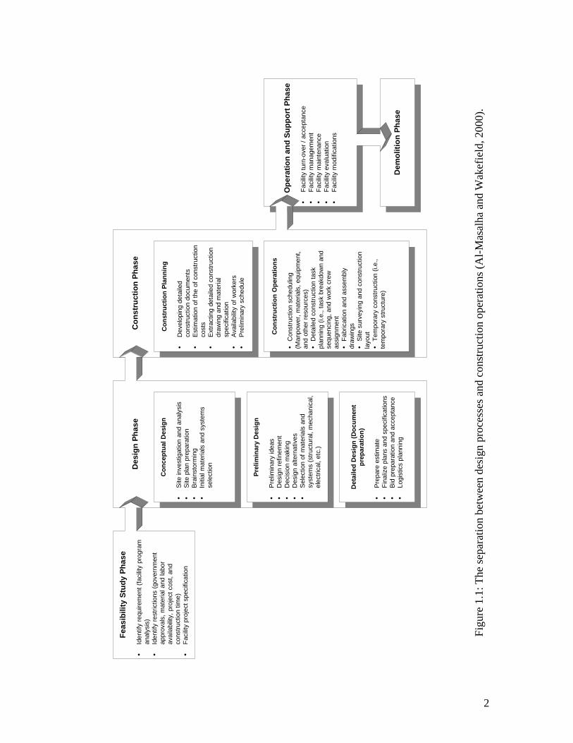
In current practice (see Figure 1.1 and Figure 1.2), designers use paper sketches to
present their schematic and preliminary ideas to clients. Then, they often transfer the final
drawings to the computer by using a Computer Aided Design (CAD) tool. Engineers use
the CAD drawings to design the corresponding mechanical, structural, and HVAC
systems. For the engineer, CAD tools are very powerful in managing measurements and
exact numbers. Finally, the construction producer or contractor face problems such as
visualizing the design, translating the design into a feasible physical reality, designing
2
Des
ign
Phas
eC
onst
ruct
ion
Phas
e
Dem
oliti
on P
hase
Con
stru
ctio
n Pl
anni
ng
Dev
elop
ing
deta
iled
cons
truct
ion
docu
men
tsE
stim
atio
n of
the
of c
onst
ruct
ion
cost
sE
xtra
ctin
g de
taile
d co
nstru
ctio
ndr
awin
g an
d m
ater
ial
spec
ifica
tion
Ava
ilabi
lity
of w
orke
rsP
relim
inar
y sc
hedu
le
Con
stru
ctio
n O
pera
tions
Con
stru
ctio
n sc
hedu
ling
(Man
pow
er, m
ater
ials
, equ
ipm
ent,
and
othe
r res
ourc
es)
Det
aile
d co
nstru
ctio
n ta
skpl
anni
ng (i
.e.,
task
bre
akdo
wn
and
sequ
enci
ng, a
nd w
ork
crew
assi
gnm
ent
Fabr
icat
ion
and
asse
mbl
ydr
awin
gsS
ite s
urve
ying
and
con
stru
ctio
nla
yout Tem
pora
ry c
onst
ruct
ion
(i.e.
,te
mpo
rary
stru
ctur
e)
O
pera
tion
and
Supp
ort P
hase
Faci
lity
turn
-ove
r / a
ccep
tanc
eFa
cilit
y m
anag
emen
tFa
cilit
y m
aint
enan
ceFa
cilit
y ev
alua
tion
Faci
lity
mod
ifica
tions
Con
cept
ual D
esig
n
Site
inve
stig
atio
n an
d an
alys
isS
ite p
lan
prep
arat
ion
Bra
inst
orm
ing
Initi
al m
ater
ials
and
sys
tem
sse
lect
ion
Prel
imin
ary
Des
ign
Pre
limin
ary
idea
sD
esig
n re
finem
ent
Dec
isio
n m
akin
gD
esig
n al
tern
ativ
esS
elec
tion
of m
ater
ials
and
syst
ems
(stru
ctur
al, m
echa
nica
l,el
ectri
cal,
etc.
)
Det
aile
d D
esig
n (D
ocum
ent
prep
arat
ion)
Pre
pare
est
imat
eFi
naliz
e pl
ans
and
spec
ifica
tions
Bid
pre
para
tion
and
acce
ptan
ceLo
gist
ics
plan
ning
Feas
ibili
ty S
tudy
Pha
se
Iden
tify
requ
irem
ent (
faci
lity
prog
ram
anal
ysis
)Id
entif
y re
stric
tions
(gov
ernm
ent
appr
oval
s, m
ater
ial a
nd la
bor
avai
labi
lity,
pro
ject
cos
t, an
dco
nstru
ctio
n tim
e)Fa
cilit
y pr
ojec
t spe
cific
atio
n
Figu
re 1
.1: T
he se
para
tion
betw
een
desi
gn p
roce
sses
and
con
stru
ctio
n op
erat
ions
(Al-M
asal
ha a
nd W
akef
ield
, 200
0).
3
construction operations and processes and making changes due to unexpected problems
that might come about during actual construction.
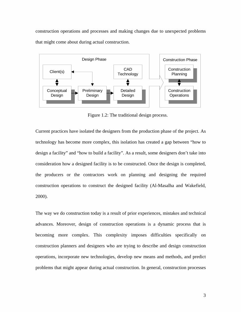
Figure 1.2: The traditional design process.
Current practices have isolated the designers from the production phase of the project. As
technology has become more complex, this isolation has created a gap between “how to
design a facility” and “how to build a facility”. As a result, some designers don’t take into
consideration how a designed facility is to be constructed. Once the design is completed,
the producers or the contractors work on planning and designing the required
construction operations to construct the designed facility (Al-Masalha and Wakefield,
2000).
The way we do construction today is a result of prior experiences, mistakes and technical
advances. Moreover, design of construction operations is a dynamic process that is
becoming more complex. This complexity imposes difficulties specifically on
construction planners and designers who are trying to describe and design construction
operations, incorporate new technologies, develop new means and methods, and predict
problems that might appear during actual construction. In general, construction processes
Construction PhaseDesign Phase
ConceptualDesign
PreliminaryDesign
DetailedDesign
CADTechnologyClient(s) Construction
Planning
ConstructionOperations
4
are difficult to describe due to the multiple and complex relationships that exist between
the various components of the constructed facility.
To overcome the aforementioned challenges, simulation networks were used to design
construction operations and analyze its behavior. However, the dynamic nature of
construction is very difficult to describe or model using the existing simulation methods
(Opdenbosh, 1994, and Naji 1997). What is needed is rather a common construction
language and an effective modeling system that can be used to capture, model, evaluate,
and improve construction operations and processes.
To respond to these challenges, this research investigates and develops a new common
taxonomy for modeling construction operations. The development of the taxonomy
requires applying several types of knowledge from different areas, including construction
operations and processes, physically-based modeling, virtual modeling, and construction
classifications. Increased understanding of these types of knowledge combined with the
common construction taxonomy presents a major opportunity for improving construction
operations.
1.2 RESEARCH PROBLEM
In the last three decades, new construction methods have been developed. These methods
introduce new products and processes that are changing the way facilities are being
constructed. Furthermore, the adaptation of current advanced technologies to the
construction domain has enhanced the understanding and improved the design and
construction processes (Opdenbosch, 1994; Naji, 1997; Beliveau et al., 1998; and
5
Wakefield, 1999). Still, the construction industry continues to strive for further
improvements. Improvements to construction operations is not something that happens
by accident or by good luck; it is achieved through systematic assessment of existing
means and methods to support enhancement to construction products and processes.
Modeling and simulation techniques are very promising for studying and analyzing
construction products and processes.
Existing modeling and simulation techniques, such as Monte Carlo simulation, try to
represent and explain construction processes and techniques, but do not consider the
geometric components, physical properties, and surrounding environment of the designed
facility (Opdenbosch, 1994, and Al-Masalha and Wakefield, 2000). Nonetheless, the
geometric representations of the construction elements and their physical behaviors are
important factors that influence the modeling of construction operations (Oloufa, 1992,
and Al-Masalha and Wakefield, 2000). Other methods attempt to simulate construction
operations by relying on geometric objects moving through an abstract space
(Hendrickson and Rehak, 1993), but they don’t consider their physical behaviors or their
surrounding environment (Hendrickson and Rehak, 1993; Naji, 1997; and Wakefield,
1999).
However, the structure of a construction system that includes the objects’ physical
behaviors and their corresponding geometrical representations is yet to be developed. On
the other hand, the development of such system is necessary to improve modeling of the
construction operations (Hendrickson and Rehak, 1993).
6
Furthermore, each modeling and simulation tool in construction uses its own
classification structure and language. There is no common construction language that can
be effectively used across the construction domain to model, analyze, and capture
construction operations. The development of a common language is an essential
foundation for improvement in construction.
To potentially improve the over all construction processes, we need to better understand
what construction operations are, how to represent and model construction operations,
how do the construction product and processes interact with each other, and develop a
system (a common construction language) that allows us to model construction
operations taking into account their environments, geometric representations, and
physical behaviors.
1.3 OBJECTIVE
The main goal of this research is to develop a new system for modeling and simulating
construction operations. This system will potentially provide the participants in the
process with an opportunity to better understand and analyze the construction operations
involved in constructing a designed facility. The specific objectives to achieve this goal
are identified as follows:
Firstly, the research will develop a common construction taxonomy that can be usefully
utilized to capture the diverse elements and model the products and processes for major
types of construction operations. The common construction taxonomy is and essential
foundation for the development of a construction language. The construction language
7
will be used to describe construction operations and processes and to provide the basis for
developing a new construction modeling system
Secondly, the research will show the limitations of existing modeling systems and the
potential uses of virtual and physically-based modeling techniques to enhance modeling
and simulation of construction operations. Virtual modeling provide the foundation to
enable virtual construction of facilities before the actual construction takes place, where
physically-based modeling has the potential to simulate construction processes, as if they
were in “real” life.
1.4 METHODOLOGY
This research introduces a new taxonomy that can be used to model, analyze, and capture
construction operations at several levels of detail. The taxonomy integrates knowledge of
design processes and products, construction processes, virtual modeling, physically-based
modeling, and construction modeling into one system. The developed taxonomy is
essential for increasing the understanding of construction processes and operations.
The following steps identify the methodology utilized by this research to achieve the
research objectives:
A) Identification of research knowledge.
The first step of the research methodology involves identification of the major types of
knowledge and key research needs to assist in developing common taxonomy. The
8
construction modeling environment requires three major categories of knowledge
identified as follows:
1. Knowledge of construction operations representations. This category of
knowledge involves analyzing construction operations at several levels of
detail. The objective of this analysis is to identify which operations can be
usefully modeled and the appropriate level of the model. Previous research
(Everett, 1991) determined that all construction operations could be
categorized into 12 basic tasks. Everett (1994) describes the “basic tasks as
the fundamental building blocks of construction field work, each representing
a series of steps that comprise an activity.”
2. Knowledge of construction objects representations. The focus of this
knowledge is on the development of a breakdown structure of the
construction objects involved in performing any operation. Modeling such
processes is difficult because of the complex nature of the relationships
between the different components involved in a given project (Opdenbosch,
1994). In addition, these relationships need to be translated into a simpler
visual construction-oriented language to simplify the modeling process.
Using an object-oriented approach will help to divide a complex project into
its major elements. These elements can be further divided until they are
simple enough to be modeled (Opdenbosch, 1994). By breaking down the
construction project into components and sub-components and defining these
9
components as objects that interact with each other and the user, the
simulation and modeling processes become easier and more effective.
3. Knowledge of physical behaviors and geometrical representations of objects.
The third area of knowledge concentrates on incorporating the physical
behaviors of the objects with their corresponding geometric representations.
In addition to the geometric representations and attributes of the objects (i.e.,
equipment, material, and building components), this area investigates the
potential use of a variety of physically-based (i.e., rigid body dynamics)
modeling techniques and virtual modeling to improve the realism and
accuracy of their representations and behaviors. For example, the objects
should not pass through each other and they should move as expected when
pushed, pulled, or lifted. By introducing the physics and virtual modeling, we
can get one step closer to mimicking the ways of doing construction in “real”
world.
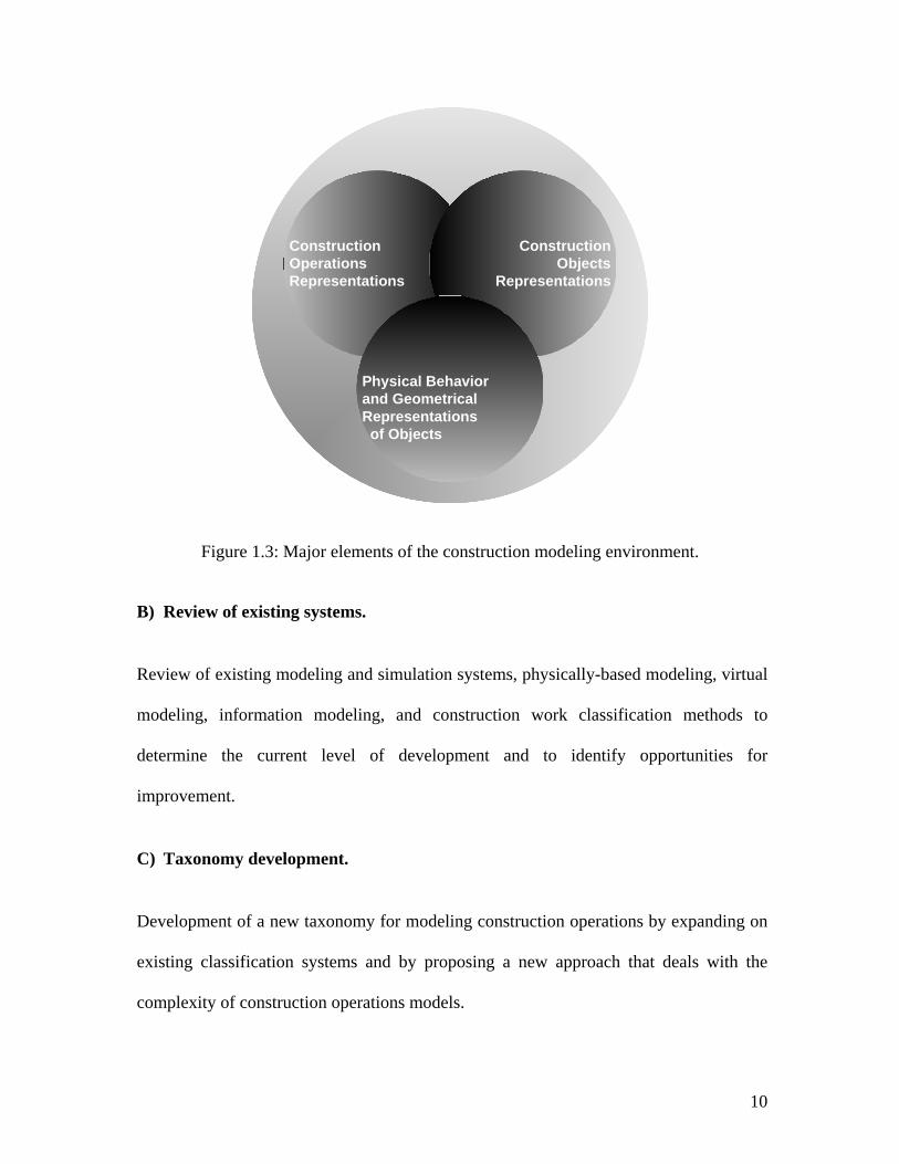
As shown in Figure 1.3, the identified areas of knowledge form the backbone structure of
the proposed construction modeling environment.
10
ConstructionOperationsRepresentations
ConstructionObjects
Representations
Physical Behaviorand GeometricalRepresentations of Objects
Figure 1.3: Major elements of the construction modeling environment.
B) Review of existing systems.
Review of existing modeling and simulation systems, physically-based modeling, virtual
modeling, information modeling, and construction work classification methods to
determine the current level of development and to identify opportunities for
improvement.
C) Taxonomy development.
Development of a new taxonomy for modeling construction operations by expanding on
existing classification systems and by proposing a new approach that deals with the
complexity of construction operations models.
11
D) Examination and validation.
Action research is utilized as the main method to evaluate, improve, and validate by
example the developed taxonomy. The methodology used to evaluate, improve, and
validate the developed taxonomy consists of the following steps:
1. Conduct pre-evaluation interviews with the participants.
2. Develop a common taxonomy for classifying construction operations.
3. Develop examples, re-evaluate, and improve the modeling system.
4. Conduct post-evaluation interviews with the participants.
5. Incorporate comments and improve upon the developed taxonomy.
6. Draw conclusions; identify areas of improvements, and potential research
extension.
1.5 CONTRIBUTION
This research starts with acknowledging the fact that a common construction language do
not exist or not widely used for representing construction products and processes which is
a major barrier to realizing the full potential of improving construction operations.
However, progress has been made. The first major contribution of this research has been
from the beginning on diminishing this barrier and enhancing construction processes
knowledge and modeling techniques by developing a new common taxonomy for
12
modeling construction operations. The taxonomy provides a structured construction
language that can be usefully utilized to model, analyze, record, and potentially improve
construction operations.
The second major contribution of this research is identifying the major types of
construction knowledge that are required to increase the understanding of construction
products and processes integration. The major types of knowledge include knowledge of
process breakdown structure, knowledge of product breakdown structure, knowledge of
resources, knowledge of construction processes, knowledge of physical and information
inputs. Further understanding of these types of knowledge provides a major opportunity
for using the developed taxonomy in performing the following activities: analyze and
record construction operations in a useful way for future improvements, evaluate and
select construction methods, identify input to products designs by analyzing and selecting
construction sequences and methods, and shorten the construction schedule by
identifying opportunities for prefabrications, pre-assembly, and modularization.
This research also provides the required guidelines for developing a virtual modeling
environment that takes into accounts the geometric representations and physical
behaviors of the components and the processes involved in shaping the product.
1.6 LIMITATIONS
The focus of this research is on the development of a modeling system and common
taxonomy for modeling construction operations. Therefore, the limitations of this
research are as follows:
13
1. The intent of this research is not to create a new virtual modeling environment,
but to show the potential benefits in utilizing virtual environments to improve
modeling of construction operations and to identify the requirement for a new
construction-modeling environment. Therefore, existing modeling and simulation
systems were employed during the course of this research to test and validate the
developed taxonomy.
2. The development and validation of the physically-based models considered here
require a long time. However, similar to the standard component representations
of CAD models, once the basic physical models are formulated, one can use them
in many construction applications (Hendrickson and Rehak, 1993). Therefore, the
focus of this research is on investigating physically-based modeling techniques
and their potential uses in modeling construction operations. Physically-based
modeling approach is an integral part of the developed taxonomy and the
development of such models is an area that requires further research and
development.
1.7 POTENTIAL OUTCOME
The developed taxonomy has the potential to improve construction research in many
areas. Potential research areas such as: 1) productivity improvement; 2) assemblage and
constructability; 3) selection of construction means and methods; 4) maintenance
techniques; 5) construction automation; and 6) capturing the knowledge of field
personnel for teaching and learning purposes.
14
1. Improve productivity. The ability to record and model construction operations in
useful way will help in setting the needed foundation to measure productivity in the
construction industry. Due to the complex nature of the construction industry it is
difficult to measure productivity. Several reports and statistical studies failed to
explain productivity changes in various industry sectors or geographical areas
(Cremeans, 1981; Everett, 1991). “Productivity is generally perceived to be a major
problem in construction” (Everett, 1991).
2. Constructability of the designed facilities can be evaluated before actual construction.
3. Selection of construction means and methods to enable better engineering decisions
throughout the design and construction processes and to answer questions such as:
What is the time needed to construct a facility? What are the cost consequences of
choosing this particular design? And what is the most appropriate method to build a
designed facility?
4. Maintenance techniques can be improved by providing adequate access, safety, and
field of view.
5. Construction automation. The proposed taxonomy will help in identifying automation
opportunities in construction and show the feasibility of developing and
implementing such opportunities in the construction industry.
6. Knowledge of field personnel can be captured for teaching and learning purposes.
The taxonomy can be used to record construction operations.
15
1.8 THESIS ORGANIZATION
This dissertation is divided into nine chapters. In Chapter One, a brief outline is provided
for research presented in this dissertation. The research problem is described. The
research methodology, limitation, contribution and potential outcomes are presented.
Chapter Two provides insight on construction modeling and simulation systems. Several
modeling and simulation techniques used in modeling construction operations are
described. Simulation and visual animation examples of a concrete slab pouring
operations are provided.
Chapter Three defines physically-based modeling techniques and their potential uses to
enhance modeling of construction operations. The concept of physically-based prototype
libraries is introduced. Examples of physically-based simulators are given from previous
research efforts.
Chapter Four concentrates on the fundamentals of virtual modeling and 4D-CAD
modeling approaches. The benefits and limitations of virtual modeling and 4D-CAD
approaches are identified.
Chapter Five describes the potential use of robotics and automation opportunities in
construction. The distribution of work between human, tools, and equipment based on
their physical and information contribution is discussed.
Chapter Six describes and analyzes classifications of construction work at several levels
of detail. The analyses are focused on identifying the construction operations that can be
16
usefully modeled and the appropriate level of the model. Process and product breakdown
structures are described.
Chapter Seven describes the developed taxonomy for modeling construction operations.
A complete description of each of the taxonometric levels is provided. The developed
taxonomy is mapped to one of the state-of-art information modeling system, industry
foundation classes, to identify the benefits of the developed taxonomy and show the
limitations of existing information modeling systems. Areas of potential concurrency
between the design process and taxonometric structure are identified. The adaptability of
the developed modeling system to approaches such as design for disassembly is discussed
and examples were presented.
Chapter Eight illustrates and validates by examples the potential uses of the developed
taxonomy to model and improve construction operations. Examples of steel structures
fabrication, assembly, and erection are provided for validation.
Chapter Nine includes a summary of the research presented in this dissertation, as well as
some possible directions for future research and extensions to the ideas in this research
are identified.
17
CHAPTER TWO: MODELING CONSTRUCTION OPERATIONS
2.1 INTRODUCTION
Simulation and modeling is a very promising tool for analyzing construction operations.
This chapter reviews general modeling and simulation systems that have been introduced
to the simulation and modeling community. Also, this chapter provides and overview of
the current state of the simulation techniques and their potential use for modeling
construction operations.
In daily construction practice, construction designers make decisions regarding complex
construction processes. These decisions include construction methods, selecting
equipment, and planning operations. In some situations, decisions are made with
unexpected outcomes. This is because of the complexity of the operations or the
difficulty in visualizing all the processes involved. In real life, testing a construction
method is very expensive and time consuming. However, simulation is a convenient
technique to model “real-life” construction operations.
18
2.2 GENERAL MODELING AND SIMULATION SYSTEMS
General modeling and simulation systems are commonly used in manufacturing and other
industries. The use of general modeling and simulation languages in construction are
demonstrated with models for equipment selection (Teicholz, 1963), for the estimation of
project durations (Carr, 1979), and for the evaluation of resource allocation strategies
(Moura, 1986).
Simulation systems can adopt one of several approaches or strategies. Three simulation
strategies are commonly recognized: event scheduling (ES), activity scanning (AS), and
process interaction (PI) (Martinez, 1996). In manufacturing and other industries, the PI
strategy combined with ES or AS is very effective in modeling systems because entities
that move have many attributes that differentiate them; and the machines or resources
that serve the entities have a few attributes, and don’t interact too much. Examples of
general modeling and simulation systems are Petri Nets, GPSS, HOCUS, SIMAN, Q-
GERT, SIMSCRIPT, SIGMA, ithink, and SLAMII (Damrianant, 1998).
2.2.1 GPSS
GPSS (General Purpose Simulation System) is a simulation modeling language that was
developed in the early 1960’s by IBM. GPSS is oriented toward queuing systems. A
GPSS simulation consists of temporary transactions and permanent facilities, which flow
around a network of block diagrams. These transactions are created and destroyed as the
simulation proceeds and which move through various GPSS blocks. There are about 40
standard building blocks in GPSS. Facilities are used to represent the resources needed by
19
the transactions at the nodes of the network (Damrianant, 1998). The most recent version
of GPSS is GPSS/World (Schriber, 1994).
GPSS/World employs a set of new GPSS Blocks and commands, which support
input/output, rescheduling, continuous and mixed modeling and multiple data types that
include integer, real, and string objects. Also, GPSS World includes an embedded
programming language called PLUS. PLUS language consists of only a few statement
types that can be used just about anywhere within the simulation, including GPSS
Blocks. This feature improved the flow of simulations. Several new GPSS Blocks have
been added to GPSS World. The new blocks such as, OPEN, CLOSE, READ, WRITE,
and SEEK Blocks provided a powerful interface to programs written in other languages.
2.2.2 HOCUS
HOCUS (Hand Or Computer Universal Simulator) (Hills, 1971), developed in the early
1960’s, enhanced and popularized the concept of activity cycle diagrams. A HOCUS
activity cycle diagram consists of two kinds of nodes: queues (circles) and activities
(boxes) connected by arrows. HOCUS could be used for both discrete and continuous
process modeling. It has been used for numerous large-scale simulations in several
industries in Europe (Poole and Szymankiewicz, 1977).
2.2.3 ITHINK
ithink is a commercial computational package that has been developed for modeling
system dynamics. ithink provides friendly user interface and animation and it can be used
to model discrete systems, such as in construction (Paulson, 1985). However, its
20
modeling methodology is difficult to use and understand when it comes to modeling
discrete systems (Damrianant, 1998).
2.2.4 SLAMII
SLAM (Simulation Language for Alternative Modeling) was developed in 1979 as a
commercial simulation language (Schriber, 1994). SLAMII was designed in 1981 as an
enhancement to SLAM. SLAM and SLAMII allow modeling in a network form. SLAMII
is a high-level simulation language with FORTRAN and C versions that can model
complicated applications. SLAMII network models can be built, animated, and run by
using another computer program named SLAMSYSTEM.
2.3 CONSTRUCTION SIMULATION USING NETWORKS
All construction process simulation tools are based on activity cyclic diagrams (ACDs)
and on activity scanning (AS) simulation strategies. For the past two decades, researchers
have recognized the need to use computer simulation to plan and analyze construction
operations and activities. Consequently, research in construction simulation and modeling
has been actively carried out, especially in academia.
2.3.1 CYCLONE (CYCLIC OPERATIONS NETWORK)
One of the first and best known simulation languages specifically designed to investigate
the use of simulation networks for modeling construction operations and activities is
CYCLONE (Cyclic Operations Network) (Halpin, 1973, 1977). The CYCLONE system
has been used frequently to model construction processes. This frequent use is due to the
ability to provide a quantitative way of viewing, planning, analyzing, and controlling the
21
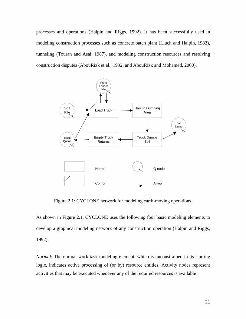
processes and operations (Halpin and Riggs, 1992). It has been successfully used in
modeling construction processes such as concrete batch plant (Lluch and Halpin, 1982),
tunneling (Touran and Asai, 1987), and modeling construction resources and resolving
construction disputes (AbouRizk et al., 1992, and AbouRizk and Mohamed, 2000).
SoilPile
Empty TruckReturns
Load Truck Haul to DumpingArea
Truck DumpsSoil
TruckQueue
FrontLoader
Idle
SoilDump
Normal
Combi
Q node
Arrow
Figure 2.1: CYCLONE network for modeling earth-moving operations.
As shown in Figure 2.1, CYCLONE uses the following four basic modeling elements to
develop a graphical modeling network of any construction operation (Halpin and Riggs,
1992):
Normal: The normal work task modeling element, which is unconstrained in its starting
logic, indicates active processing of (or by) resource entities. Activity nodes represent
activities that may be executed whenever any of the required resources is available
22
Combi: The constrained work task modeling element, which is logically constrained in
the starting logic but otherwise, is similar to the normal work task modeling element.
Queue: The idle state of a resource entity symbolically representing a queuing up or
waiting for use of passive state of resources. Nodes represent places where labor,
equipment, or materials wait before being used by an activity.
Arrows: Represent the resource entity directional flow modeling element.
In addition to the above elements, CYCLONE networks may include function elements
and counter elements. Function element is a special element that is used to consolidate or
multiply flow units. A counter element is a special element that is used to measure
productivity of the system. It is also used to control the number of times a modeled
system cycles before its completion.
MicroCYCLONE is a microcomputer-based program designed to run CYCLONE
simulation models. Before running the simulation, the graphical model network should be
converted into a numerical model using a specialized POL (Problem-Oriented Language).
Many researchers have used CYCLONE as a base to build their simulation systems such
as Insight (Paulson et al., 1987), UM-CYCLONE (Ioannou, 1989), Micro-CYCLONE
(Lluch and Halpin, 1982), and STROBOSCOPE (Martinez, 1996).
2.3.2 RESQUE
RESQUE is an acronym for RESource based QUEuing network simulation system
(Chang, 1986). RESQUE was designed as a significant enhancement to CYCLONE,
where the model is not limited to the information conveyed by the network.
23
2.3.3 COOPS
COOPS is an acronym for Construction Object Oriented Process Simulation system (Liu,
1991). It is an extension and enhancement to CYCLONE that was designed and
implemented using an object oriented programming language.
2.3.4 CIPROS
CIPROS is an acronym for Construction Integrated PROject and process planning
Simulation system (Tommelein et al., 1994). CIPROS is both a process level and a
project planning tool. It contains an expandable knowledge base of construction
techniques and methods and makes extensive use of hierarchical object-oriented
representation of resources and their properties.
2.3.5 STROBOSCOPE
Stroboscope (State and ResOurce Based Simulation of Construction ProcEsses) is a
general-purpose simulation programming language specifically designed to model
construction operations (Martinez, 1996). It is based on activity cycle diagrams (ACDs)
and the activity scanning (AS) simulation paradigm.
Stroboscope modeling elements have attributes, defined through programming
statements, which define how they behave throughout a simulation. Resources in
Stroboscope can be bulk or discrete, depending on their type. Bulk resources represent
entities that are not individual and cannot be uniquely identified, such as sand, water, etc.
Discrete resources represent unique individual entities, such as a specific truck, particular
concrete block, etc.
24
What mainly differentiate Stroboscope from other simulation tools resides in its
simulation language and its open design. Its simulation language represents resources as
objects that have assignable, persistent, and dynamic properties and can actively and
dynamically take into consideration the state of the simulation process (Martinez, 1996).
Stroboscope’s open design allows the user to determine the input and output at two
levels. The first level uses Stroboscope’s built-in programmability language. The second
level extends Stroboscope through dynamic link libraries created with high level
languages: C and C++ (Martinez, 1996).
Stroboscope includes an optional Graphical User Interface (GUI) hosted under Visio 3.0
or later version. Stroboscope also has some of the characteristics that general-purpose
programming languages have such as, built-in logarithmic and trigonometric functions,
conventional variables and arrays, and structured flow control with if-elseif-else-endif
blocks.
2.3.6 MODELING EXAMPLE UTILIZING STROBOSCOPE
A concrete slab pouring operation was selected as the case study and the Stroboscope
simulation package was used as the primary simulation environment tool. Concrete slab
placement is common and straightforward in construction. However, detailed
descriptions of the required processes, available resources and restrictions were examined
prior to the development of the simulation models as follow: the placement operation
uses ten cubic meters transit mix trucks to deliver concrete to the site from a batching
plant. The ready mix trucks are loaded one at a time at the batching plant in 5 minutes.
They travel back to the site in 8 minutes and there unload their concrete to a hoist. The
25
hoist takes two cubic meters of concrete at a time. This means that in order to completely
empty a truck, the hoist must be filled five times. It takes two minutes to fill the hoist.
When a truck is empty it travels to the batch plant in seven minutes and then waits to be
loaded again.
Once the hoist is filled with concrete at the ground floor, it hoists up to the slab being
poured in one and half minutes. There it waits until a two cubic meters concrete hopper is
empty and then fills the hopper in two and half minutes. The hoist then goes down to the
ground floor in one minute where it waits to receive another two cubic meters of concrete
from a truck.
The hopper can fill any number of empty quarter-cubic meters buggies in half a minute
each. This means that a full hopper fills eight buggies before it becomes empty. A
concrete placement crew picks up a loaded buggy, empties the concrete onto the slab and
returns the empty buggy in one minute.
There are two ready mix trucks, one hoist, one hopper, four buggies and one concrete
placement crew. The volume of concrete to be poured is seventy cubic meters.
This example was modeled using three different schemes and represented different levels
of modeling flexibility and complexity. The first model utilized Stroboscope
programmability language, while the second model employed EZStrobe graphical user
interface, and the third model used Proof animation.
The first model was developed in Stroboscope, the advanced and programmable
simulation system. This model took the longest time to develop compared to the same
26
model developed in EZStrobe. The developer had to define the resource types, network
nodes, network links, and all the simulation constraints that control the simulation in an
ASCII-like simulation code. Subsequently, the simulation code was debugged for errors
before its execution with Stroboscope simulation engine. Then the process of debugging
and running the simulation if repeated over and over again until the final the model is
produced. The following code is extracted from the simulation code for concrete
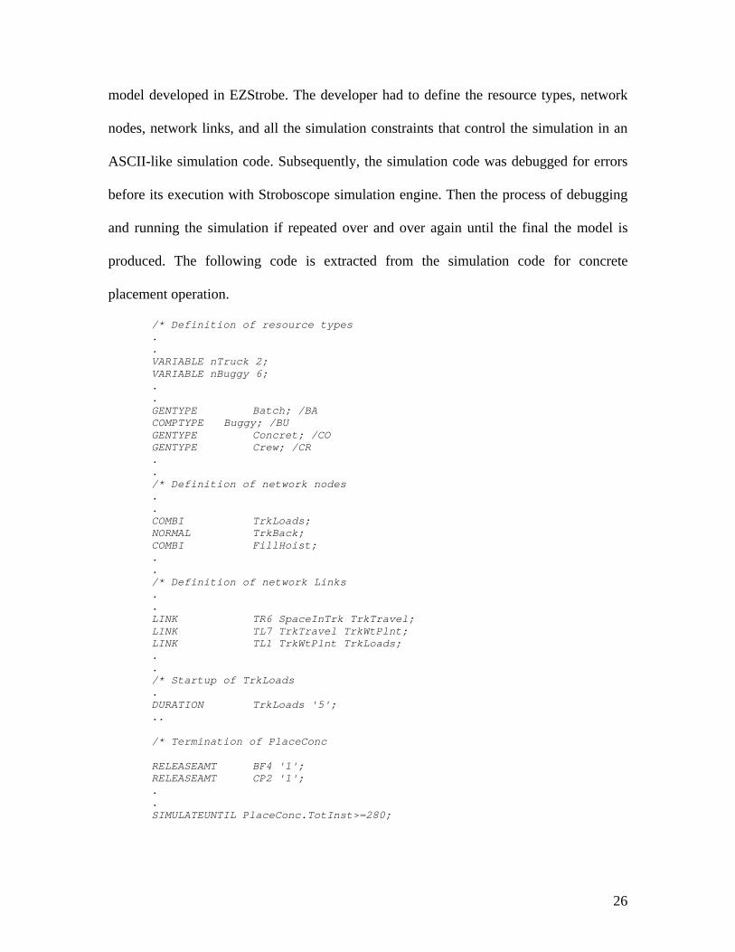
placement operation.
/* Definition of resource types . . VARIABLE nTruck 2; VARIABLE nBuggy 6; . . GENTYPE Batch; /BA COMPTYPE Buggy; /BU GENTYPE Concret; /CO GENTYPE Crew; /CR . . /* Definition of network nodes . . COMBI TrkLoads; NORMAL TrkBack; COMBI FillHoist; . . /* Definition of network Links . . LINK TR6 SpaceInTrk TrkTravel; LINK TL7 TrkTravel TrkWtPlnt; LINK TL1 TrkWtPlnt TrkLoads; . . /* Startup of TrkLoads . DURATION TrkLoads '5'; .. /* Termination of PlaceConc RELEASEAMT BF4 '1'; RELEASEAMT CP2 '1'; . . SIMULATEUNTIL PlaceConc.TotInst>=280;
27
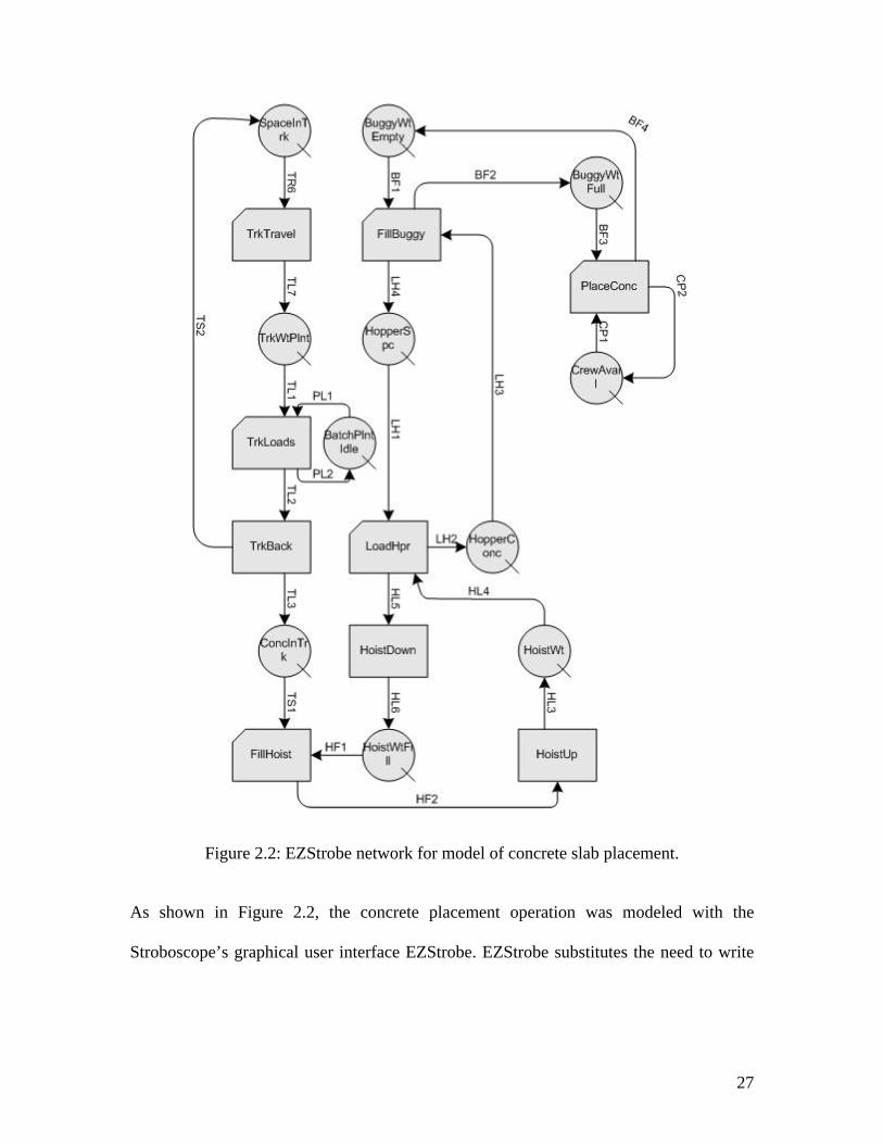
Figure 2.2: EZStrobe network for model of concrete slab placement.
As shown in Figure 2.2, the concrete placement operation was modeled with the
Stroboscope’s graphical user interface EZStrobe. EZStrobe substitutes the need to write
28
the simulation code in an ASCII-like format with a friendly, objects drag and drop, user
interface hosted under Microsoft Visio.
The third model was developed with Proof animation and Stroboscope. Proof animation
is a playback animation tool consists of two paired files. The first file, called the layout
file, is similar to a CAD-like drawing tool. It contains drawings, classes from which
objects can be created, and paths. Paths are fixed route through which objects can move
at certain speed.
The second file, called animation trace file, is produced by Stroboscope simulation
model. The trace file is a time-ordered sequence of commands that controls the dynamic
behavior of the animation. Each command specifies and event which alters the state of
the animation. For example, CREATE truck truck1 command is used to create object
TRUCK1. A PLACE TRUCK1 on truckmv command places the new object on the
truckmv path, and SET OBJECT truck1 TRAVEL 8.000000 commands specifies the
object’s speed. For example the following trace code was extracted from the source file
generated by Stroboscope.
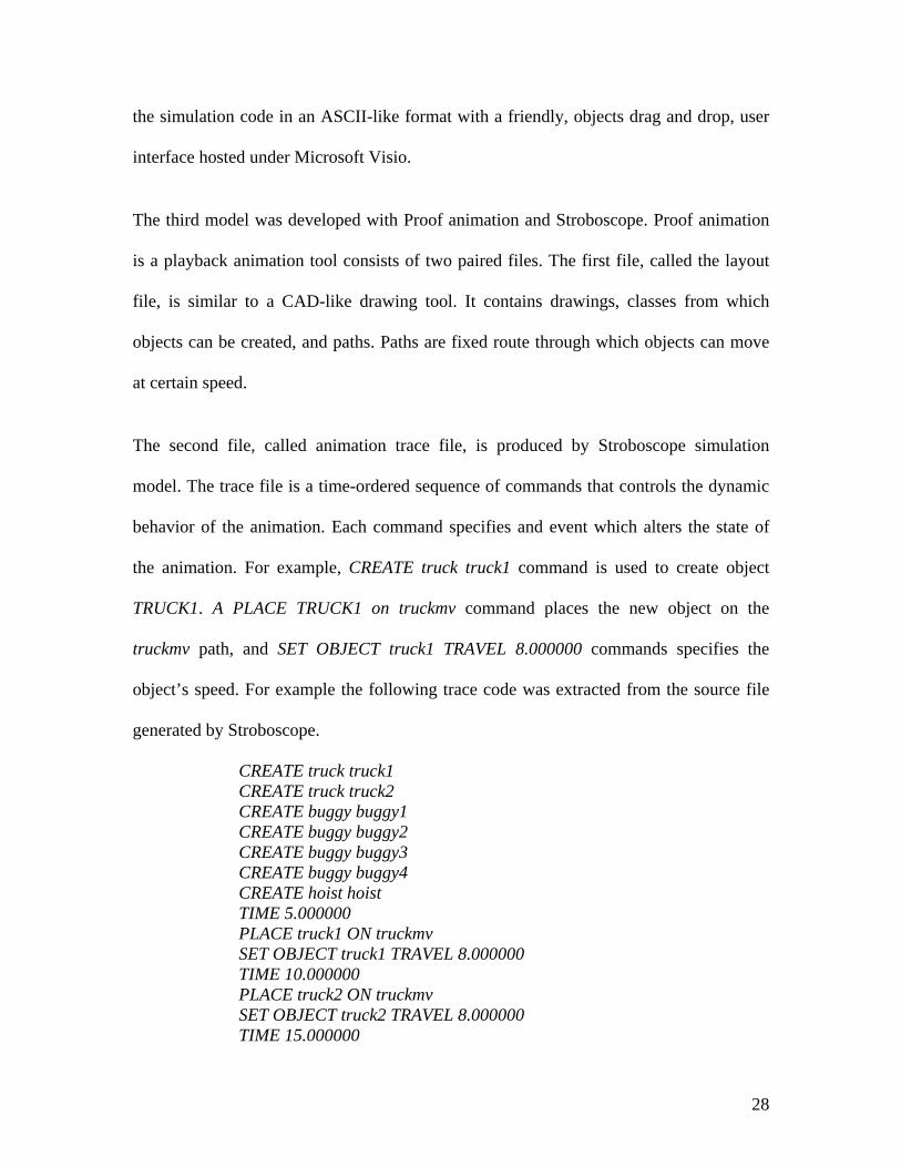
CREATE truck truck1 CREATE truck truck2 CREATE buggy buggy1 CREATE buggy buggy2 CREATE buggy buggy3 CREATE buggy buggy4 CREATE hoist hoist TIME 5.000000 PLACE truck1 ON truckmv SET OBJECT truck1 TRAVEL 8.000000 TIME 10.000000 PLACE truck2 ON truckmv SET OBJECT truck2 TRAVEL 8.000000 TIME 15.000000
29
PLACE hoist ON hoistup . . . TIME 194.500000 PLACE buggy4 ON buggygo SET OBJECT buggy4 TRAVEL 0.250000 TIME 194.750000 PLACE buggy4 ON buggybc4 SET OBJECT buggy4 TRAVEL 0.250000 TIME 195.500000
Figure 2.3: Proof animation layout and paths of concrete placement operation.
As illustrated in Figure 2.3, the layout and paths were created using Proof’s CAD-like
drawing tools. Paths such as truckmv, truckbc hoistdn, hoistup and buggygo are fixed
routes, which objects follows, while the simulation is running.
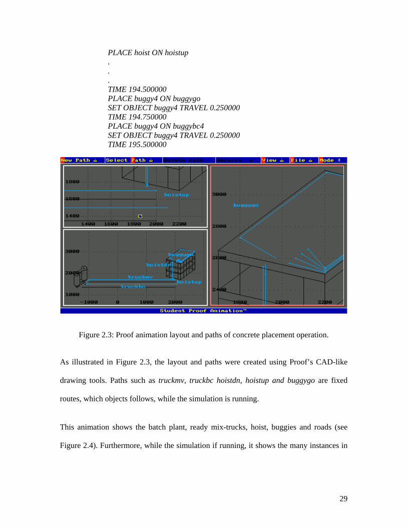
This animation shows the batch plant, ready mix-trucks, hoist, buggies and roads (see
Figure 2.4). Furthermore, while the simulation if running, it shows the many instances in
30
which Proof is used to animate a concrete placement operation. Animations were used to
simply illustrate and verify the results of the simulation model.
Figure 2.4: Proof animation of concrete placement operation.
2.4 SYNOPSIS
In this chapter, general modeling and simulation systems that are popular in the
construction community are described. Also, an overview of the current state of modeling
and simulation techniques is presented. . Concrete placement operations were modeled in
three different simulation tools: the first model utilized Stroboscope’s programmability
language, while the second model employed EZStrobe graphical user interface, and the
third model used Proof animation.
31
CHAPTER THREE: PHYSICALLY-BASED MODELING
3.1 INTRODUCTION
This chapter provides an understanding of physically-based modeling techniques and
their connections to the developed taxonomy. Due to the limited existing literature on
application of physically-based modeling techniques in construction modeling, this
chapter reviews applications from other fields, such as mechanical engineering, industrial
engineering, and computer graphics. Additionally, this review shows the advantages of
physically-based modeling techniques and their potential uses to improve construction
modeling applications.
In the past few years, physically-based modeling techniques have demonstrated that more
attractive and realistic-seeming motion can be created by subjecting objects to forces and
constraints and making the objects move as they would in physical environment
(Skolnick, 1990, Beliveau et al, 1993, and Park, 2002).
32
3.2 WHAT IS PHYSICALLY-BASED MODELING?
What is physically-based modeling? Physically-based modeling is a relatively new field
that focuses on developing methods that enable people to specify, design, control, and
build computational models of heterogeneous physical systems of objects. Barzel (1992)
defined physically-based modeling as modeling that incorporates physical characteristics
into models, allowing numerical simulation of their behavior. In addition, Park (2002)
defined a physically-based virtual reality simulator as a system of computer programs and
interfacing devices that receives users’ input in real-time interactive mode, performs
calculations for the response of physical things based on their representations, and
provides the result in 3D graphical objects in real-time.
The aim of physically-based modeling is to translate and transfer natural phenomena to a
computer program. There are two basic steps in this process: mathematical modeling and
numerical solution. The mathematical modeling is concerned with the description of the
natural phenomena through mathematical equations. Differential equations that govern
the dynamics and geometric representations of the objects are the typical ingredients of
the mathematical model. Since the natural phenomena are generally very complex, the
modeling process typically involves and requires considerable simplification. The
numerical solution involves computing an efficient and accurate solution of the
mathematical equations.
33
3.3 BENEFITS OF PHYSICALLY-BASED MODELING
Why physically-based modeling? There are many advantages to the implementation of
physically-based modeling as an integral component of the developed taxonomy. These
advantages can be listed but not limited to the following:
• Physically-based modeling facilitates the creation of models capable of automatically
synthesizing complex shapes and realistic motion.
• It adds new level of representation to graphics objects. In addition to geometry,
forces, torques, strain, mass, pressure, momentum, velocities, accelerations kinetic
and other physical quantities are used to control the creation and evolution of models.
• Physically-based models are responsive to one another and to the simulated physical
environment that they inhabit.
3.4 PHYSICALLY-BASED MODELING AND THE DEVELOPED TAXONOMY
The methodology of incorporating physically-based modeling in the developed taxonomy
for construction-based modeling environment is somewhat similar to EON and Deneb
modeling systems. Both EON and Deneb are integrated environments for development of
interactive 3D real-time simulation that incorporates the latest physically-based modeling
techniques. Objects in EON and Deneb simulations receive physical behaviors such as
weight and center of gravity. Physical forces affect their velocity, acceleration, and
rotation.
The idea is to produce a tool where most programming is done in a visual manner, by
combining small intelligent objects. By connecting existing small intelligent objects to
one another, new and more complicated objects can be formed. These newly formed
34
objects can then be transformed into new prototypes to be used in other applications. In
this context, intelligent objects are objects that will behave in a real manner according to
the physical laws.
The development and validation of the physical models requires a large amount of
developer’s time. However, the research objective is to introduce an overall framework
and to show the effectiveness of applying physically-based modeling in the development
of a construction-based modeling system. Thus, this research reviews already developed
concepts in physically-based modeling. Prototype libraries of physically-based modeling
can be usefully integrated within the developed construction-based Environment. Yet,
some specific construction tasks (i.e., the crane control system) might involve more
complex systems beyond the capacity of the physical prototype libraries. Such systems
require development of a specific task-based physically-based modeling.
3.5 PHYSICALLY-BASED SIMULATORS
Research efforts involving physically-based models and construction have been related to
the development of virtual physically-based equipment simulators. Illustrated examples
were presented by Cheok and Beck (1996), Wakefield et al. (1996), and Park (2002).
These efforts concentrated on the development of the architecture and pipeline of VR
simulator. In general, they all agree on the same architecture as shown in Figure 3.1.
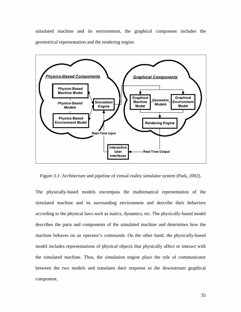
As shown in Figure 3.1, the VR simulator architecture is composed of three components
as follows: computational component, graphical component, and interactive user
interface. While the computational component includes physically-based models of the
35
simulated machine and its environment, the graphical component includes the
geometrical representation and the rendering engine.
Figure 3.1: Architecture and pipeline of virtual reality simulator system (Park, 2002).
The physically-based models encompass the mathematical representation of the
simulated machine and its surrounding environment and describe their behaviors
according to the physical laws such as statics, dynamics, etc. The physically-based model
describes the parts and components of the simulated machine and determines how the
machine behaves on an operator’s commands. On the other hand, the physically-based
model includes representations of physical objects that physically affect or interact with
the simulated machine. Thus, the simulation engine plays the role of communicator
between the two models and translates their response to the downstream graphical
component.
36
The graphical models cover the graphical and the three dimensional geometric
representations of the machine and the environment. The graphical models stored and
update the geometric data of the machine and the environment based on the information
for the simulation engine. Accordingly, the rendering engine compiles the geometric data
and interprets it in 3D rendered images format.
The last component is the real-time user interface, where the users can interact with the
simulated machine and the environment through several user input/output interfaces.
User interface includes but not limited to joysticks, control levers, handles, monitors,
HMD (head-mounted display), etc.
3.5.1 PHYSCIALLY-BASED SIMULATORS EXAMPLES
Li (1993) developed a real-time computer graphics simulator with physically-based
modeling techniques to model soil properties and behaviors in virtual environments. The
physically-based model was based on analytical methods and Newton’s laws of physics.
Thus objects will behave in a realistic manner under external forces. Along with the
physically-based models, a real-time graphics model for soil slippage and manipulation
was presented to simulate excavating activities in dynamic terrain. The environment
allows the user to dig ditches, leave tracks, produce bomb craters, pile up dirt, and push
down buildings. The developed simulator provided convincing animation of soil
movement using physically-based soil particle model; however, it didn’t address the
interaction between the soil model and the excavator model.
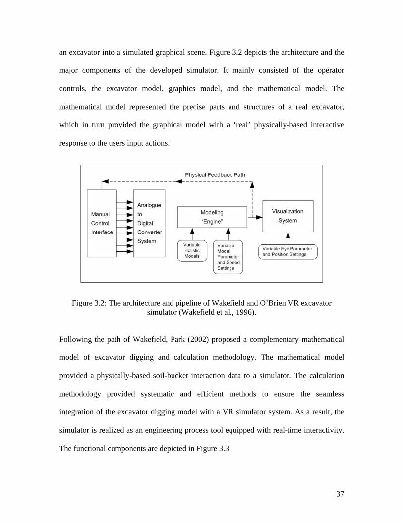
On the other hand, Wakefield et al. (1996) developed a real time interactive VR
excavator simulator, which is capable of integrating the physically-based information of
37
an excavator into a simulated graphical scene. Figure 3.2 depicts the architecture and the
major components of the developed simulator. It mainly consisted of the operator
controls, the excavator model, graphics model, and the mathematical model. The
mathematical model represented the precise parts and structures of a real excavator,
which in turn provided the graphical model with a ‘real’ physically-based interactive
response to the users input actions.
Figure 3.2: The architecture and pipeline of Wakefield and O’Brien VR excavator simulator (Wakefield et al., 1996).
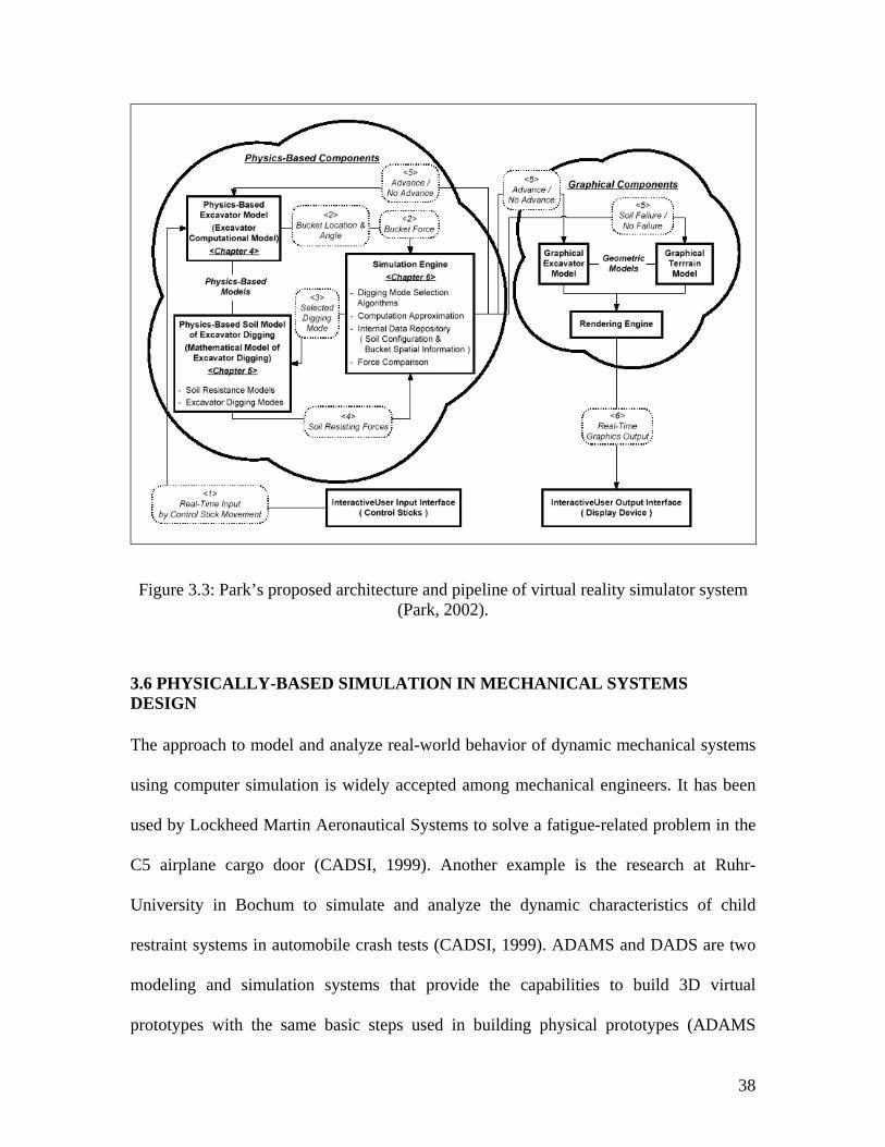
Following the path of Wakefield, Park (2002) proposed a complementary mathematical
model of excavator digging and calculation methodology. The mathematical model
provided a physically-based soil-bucket interaction data to a simulator. The calculation
methodology provided systematic and efficient methods to ensure the seamless
integration of the excavator digging model with a VR simulator system. As a result, the
simulator is realized as an engineering process tool equipped with real-time interactivity.
The functional components are depicted in Figure 3.3.
38
Figure 3.3: Park’s proposed architecture and pipeline of virtual reality simulator system (Park, 2002).
3.6 PHYSICALLY-BASED SIMULATION IN MECHANICAL SYSTEMS DESIGN
The approach to model and analyze real-world behavior of dynamic mechanical systems
using computer simulation is widely accepted among mechanical engineers. It has been
used by Lockheed Martin Aeronautical Systems to solve a fatigue-related problem in the
C5 airplane cargo door (CADSI, 1999). Another example is the research at Ruhr-
University in Bochum to simulate and analyze the dynamic characteristics of child
restraint systems in automobile crash tests (CADSI, 1999). ADAMS and DADS are two
modeling and simulation systems that provide the capabilities to build 3D virtual
prototypes with the same basic steps used in building physical prototypes (ADAMS
39
2002). These prototypes incorporate material properties such as mass, center of gravity,
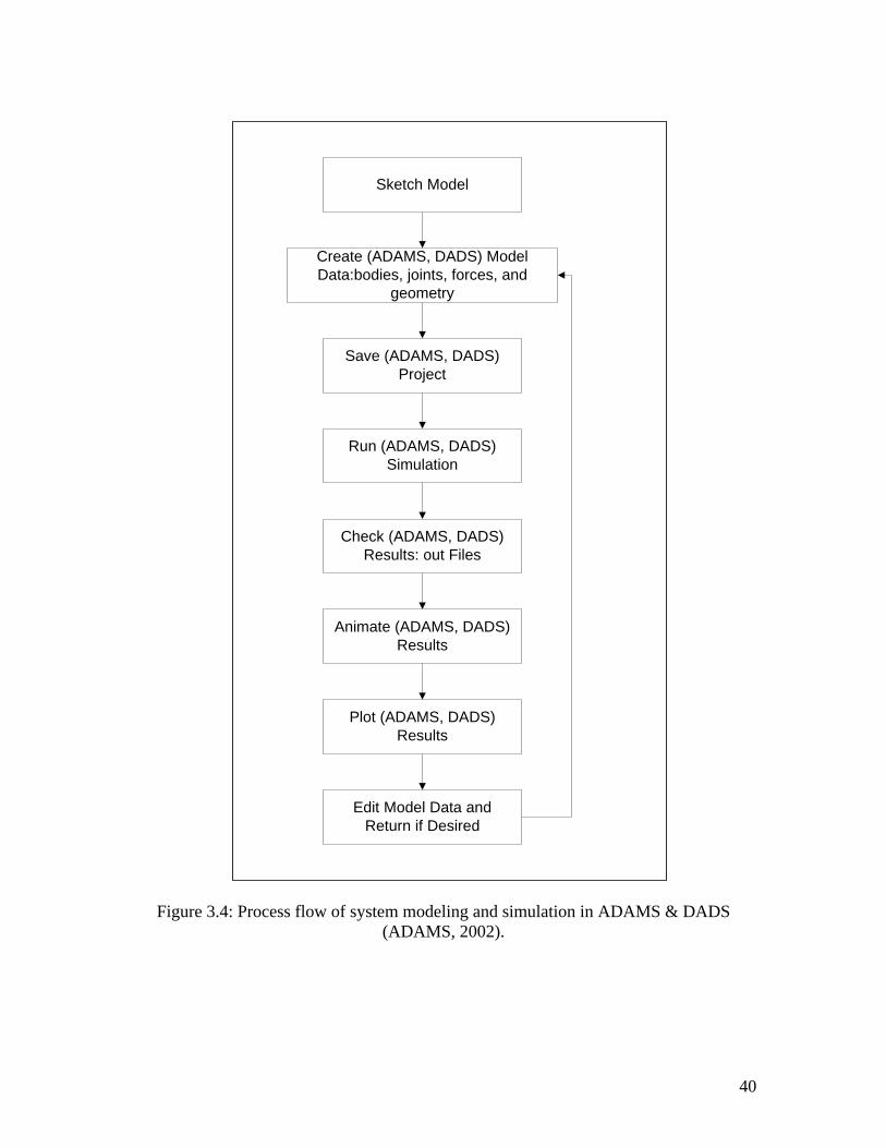
and moment of inertia. Figure 3.4 shows the steps and process involved in creating a
generic simulation model from start to end.
For example, high-rise escalators have been designed based on static loads and torques
determined from experiments. The physical experiments have a few drawbacks in that
they are expensive, time consuming, and difficult to capture the dynamic operating
condition of the escalator. To overcome these limitations, engineers at LG Industrial
Systems in Changwon, Korea (CADSI, 1999) used computer simulation as an alternative
approach in designing escalators. They used DADS, a simulation driven design software
package from CADSI that enables engineers to model, simulate, visualize, and analyze
real-world dynamic motions of 3D mechanical systems.
According to LG Industrial Systems (CADSI, 1999), the results obtained from the DADS
simulation matches very closely the results of the corresponding physical model.
Therefore, they used the computer simulation approach to improve the design process of
the high-rise escalators.
ADAMS and DADS simulations provide the following advantages:
• The ability to examine the design in many ways.
• The ability to investigate design alternatives if the initial design is not satisfactory.
• The ability to adjust the design without the cost of building hardware prototype.
40
Figure 3.4: Process flow of system modeling and simulation in ADAMS & DADS (ADAMS, 2002).
Sketch Model
Create (ADAMS, DADS) ModelData:bodies, joints, forces, and
geometry
Save (ADAMS, DADS)Project
Run (ADAMS, DADS)Simulation
Check (ADAMS, DADS)Results: out Files
Animate (ADAMS, DADS)Results
Plot (ADAMS, DADS)Results
Edit Model Data andReturn if Desired
41
3.7 PHYSICALLY-BASED MODELING IN INDUSTRIAL DESIGN SYSTEMS
Edwards and Luecke (1996) describe conceptually a physically-based modeling
technique that can be used in a computer based design system. This technique uses finite
element analysis with the B-spline basis functions to develop models of virtual
components. The technique associates the dynamics characteristics with the graphical
representations, of the virtual components, to provide realistic animated motions.
Moreover, it provides capability to interact physically with the virtual components. “The
inclusion of this type of model in a force feedback virtual environment will provide
engineers with an intuitively simple system for constructing virtual models of prototype
designs” (Edwards and Luecke, 1996).
3.8 PHYSICALLY-BASED PROTOTYPE LIBRARIES FOR RIGID-BODY MODELING
Barzel (1992) introduced a complete methodology for constructing prototype libraries of
computer graphics routines for physical based-modeling. He examined closely what it
means to construct a model of a real-world object and provided explicit means of
describing and controlling such models and their behaviors. The objective of the
prototype library is to serve as a general, reusable, and extensible library for rigid-body
dynamics modeling. The library includes four modules with unique features. The library
and the features embedded in the modules were used to describe the development of
several physically-based models such as, a swinging chain model, and tennis ball cannon.
The four modules in the prototype library are (Barzel, 1992):
• The coordinate frames module, which provides a common framework for working
with 3D coordinates geometry.
42
• The kinematic rigid-bodies module, which defines the rigid-body motion (i.e., motion
without regard to force or inertia).
• The dynamic rigid-bodies module, which provides classical Newtonian mechanics.
• The “fancy forces” module, which provides a mechanism to specify forces for the
Newtonian model and support geometric constraints on bodies.
The prototype library includes the following features for rigid-body modeling (Barzel,
1992):
• Basic Newtonian motion of rigid bodies in response to forces and torques.
• The ability to measure the work done by each force and torque and balance it against
the kinetic energy of the bodies.
• Support for various kinds of forces including dynamic constraints to allow constraint-
based control.
• The ability to handle discontinuities in a model.
• The ability to be expanded, both by enhancing the existing modules and by adding
additional modules.
Unlike conventional modeling techniques where models have only geometric properties,
physically-based models have physical properties and their motion is subject to physical
laws, such as Newton’s second law of motion. In general, physically-based modeling
combines the distinct steps which are modeling, rendering, and animation (Barzel, 1992).
43
3.9 EXAMPLE OF PHYSICALLY-BASED MODELING (RIGID BODY DYNAMICS)
A rigid body is an object with physical properties such as mass, center of mass and
volume. It is neither flexible nor deformable. Integrating rigid body dynamics in 3D
modeling environment enables 3D objects to move sensibly when influenced by a force
such as gravitation.
EON simulation supports the idea of integrating rigid body dynamics into a 3D modeling
environment. EON is a high performance toolkit for creating interactive, real-time 3D
simulations. EON Users can define behaviors and interactions, as well as test simulations
and change parameters, all in real-time (EON Reality, 2002). EON is a PC platform tool
for enhancing the display of 3D objects, not for building the objects themselves. Objects
in EON simulation receive physical behaviors such as weight and center of gravity,
where their velocity, acceleration, and rotation are affected by physical forces.
As shown in Figure 3.5, a Force Node has been added to EON simulation tree. Then the
Force Node was specified as a prototype node for rigid bodies only. Now, the Force
Node prototype can be applied to all the rigid bodies in the modeling environment. As
illustrated in Figure 3.5, the Force node is simultaneously attached to the Ball and Chair
objects.
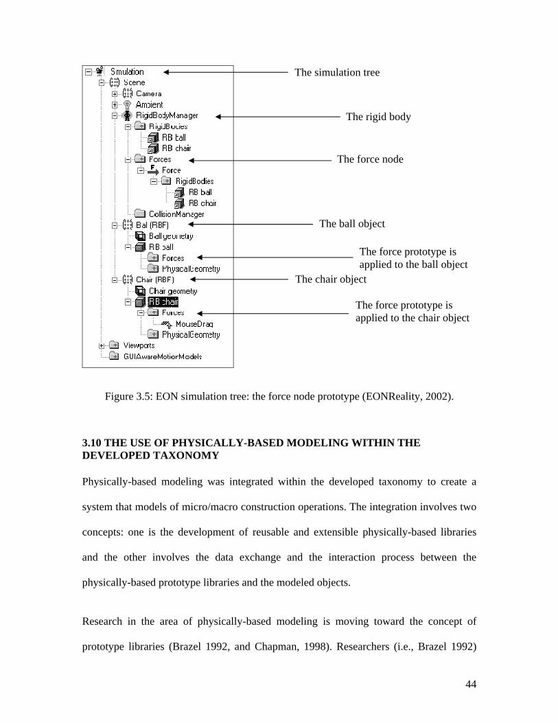
44
Figure 3.5: EON simulation tree: the force node prototype (EONReality, 2002).
3.10 THE USE OF PHYSICALLY-BASED MODELING WITHIN THE DEVELOPED TAXONOMY
Physically-based modeling was integrated within the developed taxonomy to create a
system that models of micro/macro construction operations. The integration involves two
concepts: one is the development of reusable and extensible physically-based libraries
and the other involves the data exchange and the interaction process between the
physically-based prototype libraries and the modeled objects.
Research in the area of physically-based modeling is moving toward the concept of
prototype libraries (Brazel 1992, and Chapman, 1998). Researchers (i.e., Brazel 1992)
The force node
The rigid body
The ball object
The chair object
The force prototype is applied to the ball object
The force prototype is applied to the chair object
The simulation tree
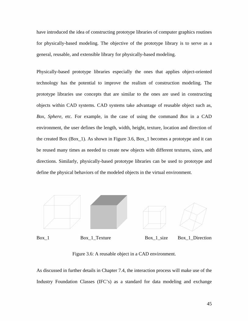
45
have introduced the idea of constructing prototype libraries of computer graphics routines
for physically-based modeling. The objective of the prototype library is to serve as a
general, reusable, and extensible library for physically-based modeling.
Physically-based prototype libraries especially the ones that applies object-oriented
technology has the potential to improve the realism of construction modeling. The
prototype libraries use concepts that are similar to the ones are used in constructing
objects within CAD systems. CAD systems take advantage of reusable object such as,
Box, Sphere, etc. For example, in the case of using the command Box in a CAD
environment, the user defines the length, width, height, texture, location and direction of
the created Box (Box_1). As shown in Figure 3.6, Box_1 becomes a prototype and it can
be reused many times as needed to create new objects with different textures, sizes, and
directions. Similarly, physically-based prototype libraries can be used to prototype and
define the physical behaviors of the modeled objects in the virtual environment.
Box_1 Box_1_Texture Box_1_size Box_1_Direction
Figure 3.6: A reusable object in a CAD environment.
As discussed in further details in Chapter 7.4, the interaction process will make use of the
Industry Foundation Classes (IFC’s) as a standard for data modeling and exchange
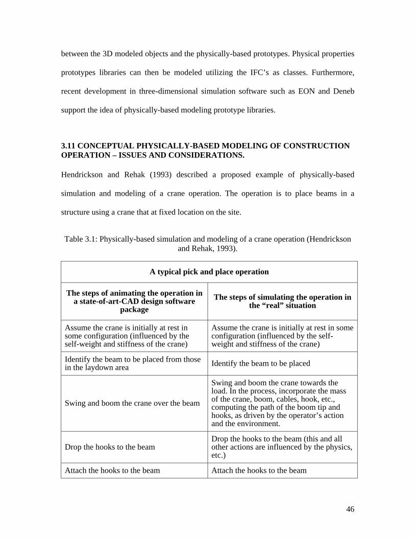
46
between the 3D modeled objects and the physically-based prototypes. Physical properties
prototypes libraries can then be modeled utilizing the IFC’s as classes. Furthermore,
recent development in three-dimensional simulation software such as EON and Deneb
support the idea of physically-based modeling prototype libraries.
3.11 CONCEPTUAL PHYSICALLY-BASED MODELING OF CONSTRUCTION OPERATION – ISSUES AND CONSIDERATIONS.
Hendrickson and Rehak (1993) described a proposed example of physically-based
simulation and modeling of a crane operation. The operation is to place beams in a
structure using a crane that at fixed location on the site.
Table 3.1: Physically-based simulation and modeling of a crane operation (Hendrickson and Rehak, 1993).
A typical pick and place operation
The steps of animating the operation in a state-of-art-CAD design software
package The steps of simulating the operation in
the “real” situation
Assume the crane is initially at rest in some configuration (influenced by the self-weight and stiffness of the crane)
Assume the crane is initially at rest in some configuration (influenced by the self-weight and stiffness of the crane)
Identify the beam to be placed from those in the laydown area Identify the beam to be placed
Swing and boom the crane over the beam
Swing and boom the crane towards the load. In the process, incorporate the mass of the crane, boom, cables, hook, etc., computing the path of the boom tip and hooks, as driven by the operator’s action and the environment.
Drop the hooks to the beam Drop the hooks to the beam (this and all other actions are influenced by the physics, etc.)
Attach the hooks to the beam Attach the hooks to the beam
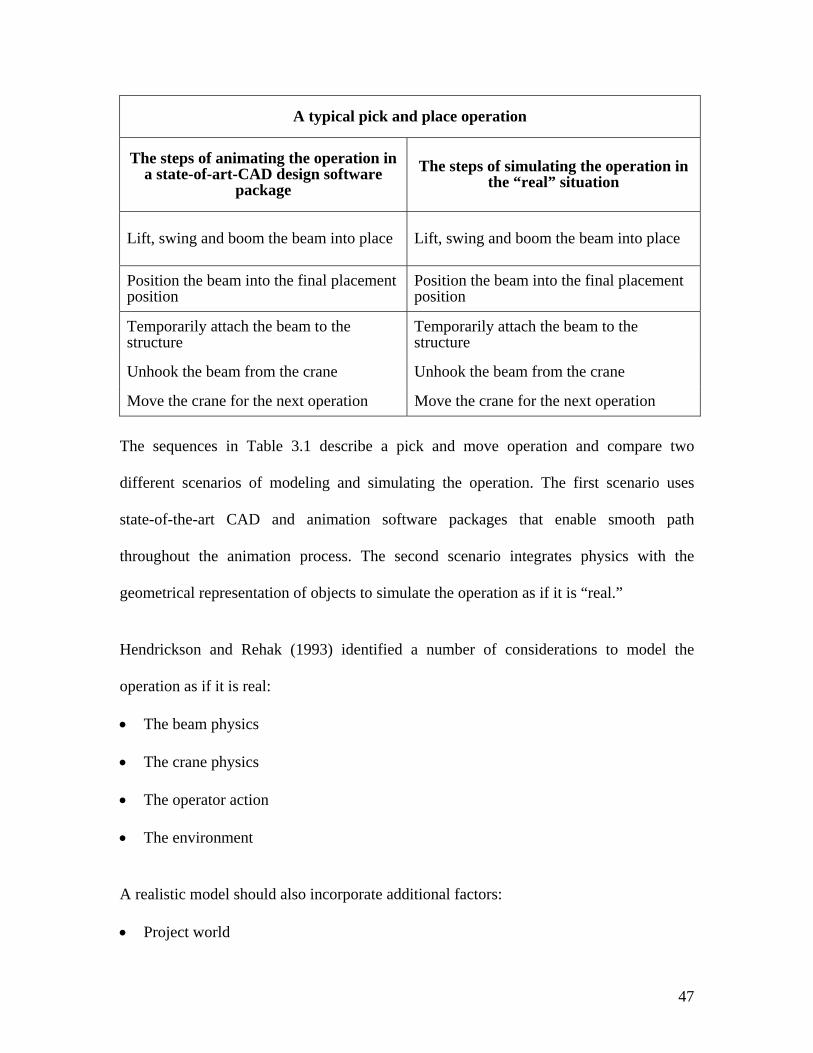
47
A typical pick and place operation
The steps of animating the operation in a state-of-art-CAD design software
package The steps of simulating the operation in
the “real” situation
Lift, swing and boom the beam into place Lift, swing and boom the beam into place
Position the beam into the final placement position
Position the beam into the final placement position
Temporarily attach the beam to the structure
Temporarily attach the beam to the structure
Unhook the beam from the crane Unhook the beam from the crane
Move the crane for the next operation Move the crane for the next operation
The sequences in Table 3.1 describe a pick and move operation and compare two
different scenarios of modeling and simulating the operation. The first scenario uses
state-of-the-art CAD and animation software packages that enable smooth path
throughout the animation process. The second scenario integrates physics with the
geometrical representation of objects to simulate the operation as if it is “real.”
Hendrickson and Rehak (1993) identified a number of considerations to model the
operation as if it is real:
• The beam physics
• The crane physics
• The operator action
• The environment
A realistic model should also incorporate additional factors:
• Project world
48
• Communication
• Control
• Sensing
According to Hendrickson and Rehak (1993), “While developing and validating physical
models of the type described above may be time-consuming, the basic models should be
able to be re-used in numerous construction applications in the same way that standard
component representations are re-used in CAD models.”
Hendrickson and Rehak have speculated on the topic of physically-based simulation in
construction before computing technology was up to the task. Thus, the development of
physically-based simulation in construction was complex and difficult to achieve. While,
they have conceptually described an example of a typical crane motion, a pick and place
operation, no further exploration was made and no applications were developed beyond
the crane conceptual example. To date, computing technology is up to the task; however,
there has been little substantive effort toward developing a physically-based modeling
system in construction.
3.12 EXAMPLE: A CRANE LIFT OPERATION
This section reviews issues that need to be considered when modeling a construction
object in line with the developed taxonomy. These issues are discussed below by looking
at the individual components that constitute a crane lift operation. A crane lift operation
involves the following objects and players: the object to be lifted (in this case a beam, a
crane), the surrounding environment and an operator. Every object or player requires a
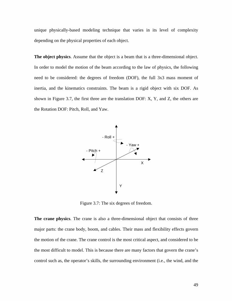
49
unique physically-based modeling technique that varies in its level of complexity
depending on the physical properties of each object.
The object physics. Assume that the object is a beam that is a three-dimensional object.
In order to model the motion of the beam according to the law of physics, the following
need to be considered: the degrees of freedom (DOF), the full 3x3 mass moment of
inertia, and the kinematics constraints. The beam is a rigid object with six DOF. As
shown in Figure 3.7, the first three are the translation DOF: X, Y, and Z, the others are
the Rotation DOF: Pitch, Roll, and Yaw.
Figure 3.7: The six degrees of freedom.
The crane physics. The crane is also a three-dimensional object that consists of three
major parts: the crane body, boom, and cables. Their mass and flexibility effects govern
the motion of the crane. The crane control is the most critical aspect, and considered to be
the most difficult to model. This is because there are many factors that govern the crane’s
control such as, the operator’s skills, the surrounding environment (i.e., the wind, and the
- Pitch +- Yaw +
- Roll +
X
Y
Z
50
thermal effect), and the non-linear motion of the cable. Also, another aspect that needs to
be considered is the deflection of the boom and the expansion of the cable under load.
There are two issues other than the object physics and the crane physics that are
considered critical to the developed modeling taxonomy. The two issues are the
surrounding environment and the operator actions. The surrounding environment adds
another dimension to the complexity level of the developed modeling taxonomy. The
surrounding environment such as the wind and other natural forces affects the stability of
the crane under operation. Consequently, its inclusion will result in a change in the
numerical model of the physical representation of the crane.
In addition to the surrounding environment the operators’ actions affect the physically-
based modeling of the crane in an indirect way. The operator skills have been used as a
control technique during crane operations. It is an issue that affects the crane operations,
however, operator actions won’t affect the physically-based modeling of the crane or the
load it self.
Physically-based modeling of a crane operation also involves several other issues that are
not considered here of due to complexity issues. The above analysis does not intend to
describe a detailed physically-based modeling of a crane operation rather than it is aimed
at shedding the light on major elements that may be essential to the development of a
physically-based crane model.
51
3.13 SYNOPSIS
This chapter presents physically-based modeling techniques and their connections to the
developed taxonomy. Literature on the applications of physically-based modeling
techniques were found to be limited, therefore applications from other fields, such as
mechanical engineering, industrial engineering, and computer graphics are also reviewed.
Additionally, this chapter establishes the advantages of applying physically-based
techniques to construction modeling applications.
52
CHAPTER FOUR: VIRTUAL ENVIRONMENTS
4.1 INTRODUCTION
This chapter concentrates on providing an understanding of the fundamentals of virtual
reality technology and the applications of virtual and 4D-CAD in construction modeling.
Also, the benefits and limitations of virtual reality and 4D-CAD approaches as they relate
to the developed modeling system in this research are identified. This review is important
before we describe the proposed taxonomy for modeling construction operations, which
will be described in chapter seven.
4.2 DEFINITIONS OF VIRTUAL REALITY
Virtual reality (VR), virtual environment (VE), virtual world or microworld are
equivalent names that refer to the same concept. Many definitions for VR can be found
in the literature due to the interdisciplinary nature of the field. Nevertheless, the different
definitions agree on some basic elements of VR. Namely, a VR system is a combination
of a human participant, human-machine interfaces, and a computer with the objective of
53
immersing the VR participant in an interactive environment, which contain 3D objects
with 3D locations, and orientations in 3D space.
The CAVE (Automatic Virtual Environment) is a projection-based VR system that
surrounds the user with four screens. The screens are arranged in a cube made up of three
rear-projection screens for walls and a down-projection screen for the floor. A user wears
stereo shutter glasses and a six-degrees-of-freedom head-tracking device. As the user
moves inside the CAVE, the correct stereoscopic perspective projections are calculated
for each wall. A second sensor and buttons in a wand held by the user provide interaction
with the VE.
VR can be defined as follows (Gigante, 1994):
"The illusion of participation in a synthetic environment rather than external observation
of such an environment. VR relies on 3D stereoscopic head-tracked displays, hand/body
tracking, and binaural sound. VR is an immersive, multi-sensory experience."
VR can also be defined as follows (Furness and Barfield, 1995):
"The representation of a computer model or database which can be interactively
experienced and manipulated by the VE participant(s)."
The difference between a VR system and conventional computer graphics is that, in the
latter, the user is like an external observer looking through a window while in the former,
the user is a participant in the synthetic environment. Other concepts related to VR are
the following:
54
• Virtual image (Furness and Barfield, 1995): the visual, auditory, tactile and
kinesthetic stimuli, which are conveyed to the sensory such that they appear to
originate from within the 3D space surrounding VR participant.
• Virtual interface (Furness and Barfield, 1995): a system of transducers, signal
processors, computer hardware and software that creates an interactive medium.
• Augmented reality (Durlach and Mavor, 1994): “the use of transparent head-mounted
displays that superimpose synthetic elements on a view of real surrounding.”
• Artificial reality (Gigante, 1994): video-based, computer mediated interactive media.
• Cyberspace (Gigante, 1994): a global information and entertainment network.
4.3 HISTORY OF VIRTUAL REALITY
VR is often thought as a new technology, but its development actually dates back almost
40 years ago. In 1962, Heilig (Gigante, 1994) presented the Sensorama, which was the
first multi-sensural simulator where the viewer could take a motorcycle ride through New
York City. The simulator constituted a VR system with the lack of interactivity. In the
middle 60's, Sutherland (Ellis, 1995) developed fast graphics hardware for the purpose of
experiencing computer-synthesized environments through head mounted displays. In the
70’s, Krueger (Ellis, 1995) implemented an interactive environment that was projected
onto a wall-sized screen. Krueger’s environment is an early version of what we know
now as the Cave Automated Virtual Environment (CAVE), developed by the University
of Illinois.
In the 80’s, great advances were achieved in the area of vehicle-simulators, especially
military flight simulator (Gigante, 1994). Since teaching some of the flight skills on real
55
vehicles were dangerous and/or expensive, it was important to develop flight simulators
for training and testing of new technology and procedures. In the middle 1980’s, the
Virtual Interactive Environment workshop (VIEW) developed a general-purpose, multi-
sensory, personal simulator device (Ellis, 1995). There are numerous other applications
and contributions in the field of VR from different research groups and entertainment
industries that can be found in the literature.
4.4 USING VR AS A DESIGN TOOL
At the LEGO group, maker of the world’s most popular toys, engineers and designers are
working in collaborative and immersive simulation based environment. The LEGO group
has been engaged in CAD engineering for many years. The company uses a 3D graphics
database of toy kit elements to develop future toys. The design team uses the database
with Multigen’s immersive 3D-scene assembly package, SmartScene, to create the LEGO
virtual village (LEGO, 1998). The designer enters the LEGO village by putting
headmount displays and pinch gloves that are equipped with a tracker system. Inside the
VE, the designer accesses hundreds of photorealistic LEGO parts. They appear in mid-
air, ready to grab by hand for building. After the scene is complete, the system generates
a parts list and a physical model is then generated. If it looks promising in physical
reality, then it is ready to be manufactured. This case of the LEGO group demonstrates
the use of a non-sequential design process within a VE.
4.5 USING VR TO IMPROVE DESIGN PROCESSES
Chrysler uses VR technology to improve both interior and exterior aesthetic evaluations
in the early stages of the design (product) development. According to Ken Socks
56
(Chrysler, 1998), an engineer at Chrysler, “to accurately evaluate and modify designs,
you need accurate representations of them in a VE. Our models are really more accurate
than a physical prototype because they’re based on all of the actual CAD models.”
Therefore, the use of VR in the design process may improve the design quality, enhances
product safety, and reduces cost. Additionally, with the ability to see, walk, reach, and
grasp in the virtual world, manufacturers can train personnel and greatly improve
worker’s safety and productivity.
4.6 AUGMENTED REALITY IN CONSTRUCTION
Augmented reality is poised as a new technology ready to tackle many real world
applications. Augmented reality is generally defined as enhancing the real world with
computer-generated information to improve understanding. There are many applications
that can take advantage of augmented reality systems: entertainment, manufacturing,
assembly, product design, medical training, collaborative work, scientific visualization,
architecture design, construction, and any area that can be reasonably enhanced.
Augmented reality has been used at the Columbia University by Anthony et al. (1996) to
develop systems that improve the methods for the construction, inspection, and
renovation of architectural structures. Webster et al. (1996) demonstrated an experimental
augmented reality system that shows the locations of columns behind a finished wall, to
determine the locations of re-bars inside one of the columns, and to conduct structural
analysis of the column (Webster et al., 1996).
57
4.7 VIRTUAL ENVIRONMENTS IN ARCHITECTURE
VE is a system that creates an artificial three-dimensional world where communication is
interactive with an immediate response. Also, it is a real-time simulation technology
where the viewer is able to move about the 3D model.
VE create a powerful sense of immersion inside a 3D graphical computer model.
Participants are immersed and surrounded by information, which is to scale and three-
dimensional. The Cave Automatic Virtual Environment (CAVE) interface is intuitive to
use for exploring VE because it is tightly coupled with the way people explore real
environments. Viewers can look around in the 3D building model by turning and moving
their heads, as they do naturally in a real space.
VE systems combine a head mounted stereo display device with data gloves, data suits,
and similar devices that interpret bodily movement. VE systems allow the user to “pick
up” full scale three-dimensional geometrical entities and “carry” them to where the user
wants to locate them in space (Licklider et al., 1978).
4.8 VR MODELING TECHNIQUES IN ARCHITECTURE
VR have the potential to be excellent representation tools for helping designers make
decisions about architectural spaces before they are built. Engeli and Kurmann (1996)
introduced a new method of modeling 3D architecture spaces to support design
development in the early stage using VR. As a demonstration of their idea they developed
SCULPTOR, which is a computer tool for virtual design in architecture. SCULPTOR
adopted the idea of modeling void architectural spaces as its main modeling technique.
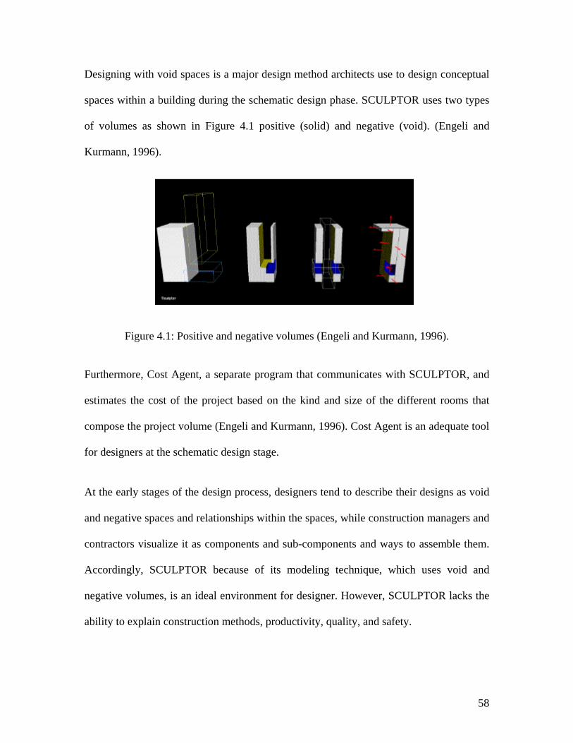
58
Designing with void spaces is a major design method architects use to design conceptual
spaces within a building during the schematic design phase. SCULPTOR uses two types
of volumes as shown in Figure 4.1 positive (solid) and negative (void). (Engeli and
Kurmann, 1996).
Figure 4.1: Positive and negative volumes (Engeli and Kurmann, 1996).
Furthermore, Cost Agent, a separate program that communicates with SCULPTOR, and
estimates the cost of the project based on the kind and size of the different rooms that
compose the project volume (Engeli and Kurmann, 1996). Cost Agent is an adequate tool
for designers at the schematic design stage.
At the early stages of the design process, designers tend to describe their designs as void
and negative spaces and relationships within the spaces, while construction managers and
contractors visualize it as components and sub-components and ways to assemble them.
Accordingly, SCULPTOR because of its modeling technique, which uses void and
negative volumes, is an ideal environment for designer. However, SCULPTOR lacks the
ability to explain construction methods, productivity, quality, and safety.
59
4.9 PROTOTYPING TECHNIQUES USING CAD AND VR
Prototyping is a technique to generate designs quickly in both conventional CAD and
computer graphics systems. Conventional CAD systems use the “library” approach that
provides a choice of elements, which can be copied into the new design (Coomans and
Oxman, 1996). These elements could be statically defined such as furniture and
engineering symbols, or could be parametric such as doors and windows. “Menu” is
another common approach in computer graphics systems, which provides a menu of
elements and also a range of possible procedural operations upon these elements
(Coomans and Oxman, 1996). The second approach is more appropriate for modeling
construction operations because of the ability to add intelligence to the element behaviors
with respect to the corresponding construction operation. Intelligence means that the
elements or the components involved in any construction operation will behave to a
certain degree within the VR as it would in the “real” world. The physical behavior of the
element within the VR could be one form of intelligence. For example, objects fall down
when released in the air.
Coomans and Oxman (1996) developed their prototype system called VIDE, the acronym
for Virtual Interactive Design Environment. The main purpose of developing VIDE is to
investigate the technical practicability of a VR based design system. The VIDE design
system capabilities were devoted and limited to the room design task. The system allows
the users to define the room design components such as apace boundaries, boundary
penetrations, and furnishing. It also restricts the operations that can be performed on
those components to adding, removing, and relocating. The idea of breaking down a
project into its component, material or design space components, and defining tasks that
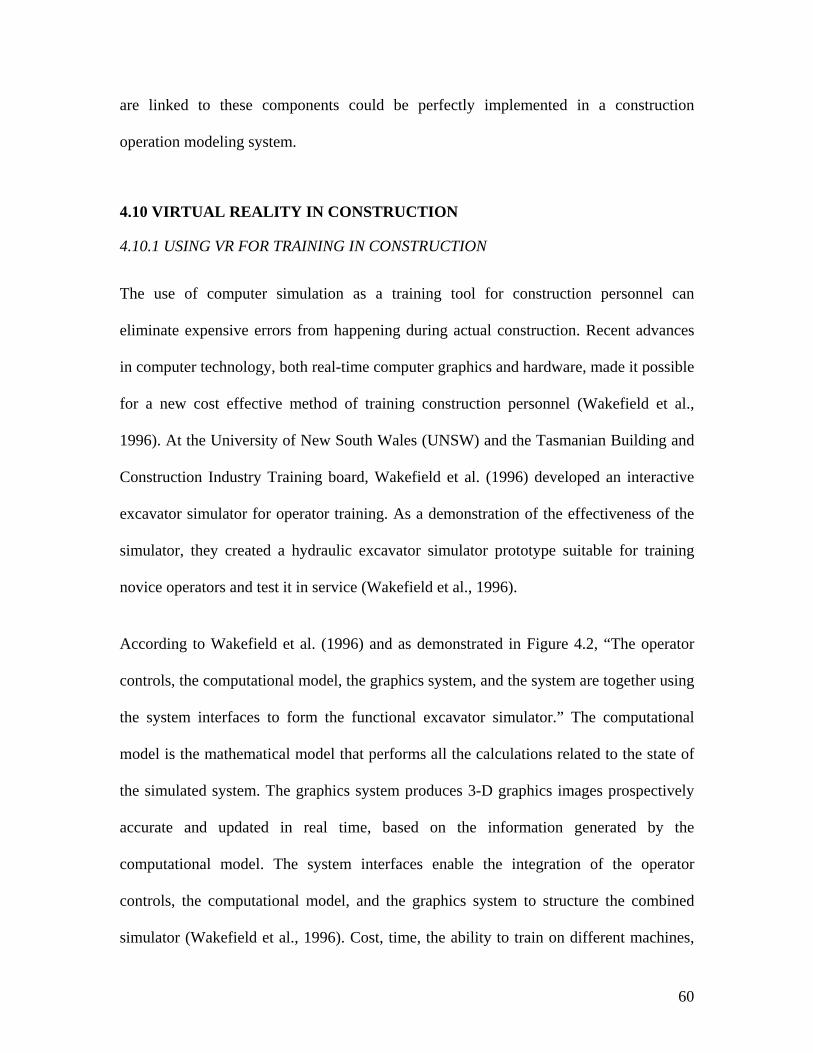
60
are linked to these components could be perfectly implemented in a construction
operation modeling system.
4.10 VIRTUAL REALITY IN CONSTRUCTION
4.10.1 USING VR FOR TRAINING IN CONSTRUCTION
The use of computer simulation as a training tool for construction personnel can
eliminate expensive errors from happening during actual construction. Recent advances
in computer technology, both real-time computer graphics and hardware, made it possible
for a new cost effective method of training construction personnel (Wakefield et al.,
1996). At the University of New South Wales (UNSW) and the Tasmanian Building and
Construction Industry Training board, Wakefield et al. (1996) developed an interactive
excavator simulator for operator training. As a demonstration of the effectiveness of the
simulator, they created a hydraulic excavator simulator prototype suitable for training
novice operators and test it in service (Wakefield et al., 1996).
According to Wakefield et al. (1996) and as demonstrated in Figure 4.2, “The operator
controls, the computational model, the graphics system, and the system are together using
the system interfaces to form the functional excavator simulator.” The computational
model is the mathematical model that performs all the calculations related to the state of
the simulated system. The graphics system produces 3-D graphics images prospectively
accurate and updated in real time, based on the information generated by the
computational model. The system interfaces enable the integration of the operator
controls, the computational model, and the graphics system to structure the combined
simulator (Wakefield et al., 1996). Cost, time, the ability to train on different machines,
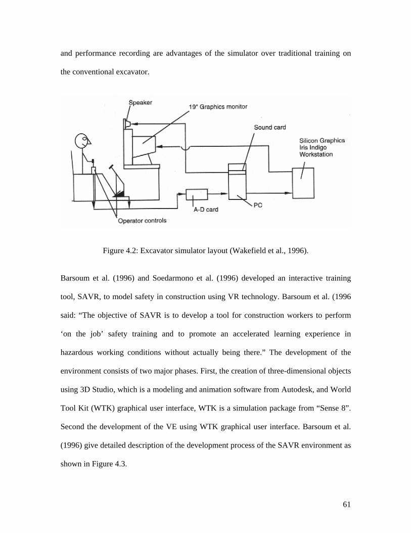
61
and performance recording are advantages of the simulator over traditional training on
the conventional excavator.
Figure 4.2: Excavator simulator layout (Wakefield et al., 1996).
Barsoum et al. (1996) and Soedarmono et al. (1996) developed an interactive training
tool, SAVR, to model safety in construction using VR technology. Barsoum et al. (1996
said: “The objective of SAVR is to develop a tool for construction workers to perform
‘on the job’ safety training and to promote an accelerated learning experience in
hazardous working conditions without actually being there.” The development of the
environment consists of two major phases. First, the creation of three-dimensional objects
using 3D Studio, which is a modeling and animation software from Autodesk, and World
Tool Kit (WTK) graphical user interface, WTK is a simulation package from “Sense 8”.
Second the development of the VE using WTK graphical user interface. Barsoum et al.
(1996) give detailed description of the development process of the SAVR environment as
shown in Figure 4.3.
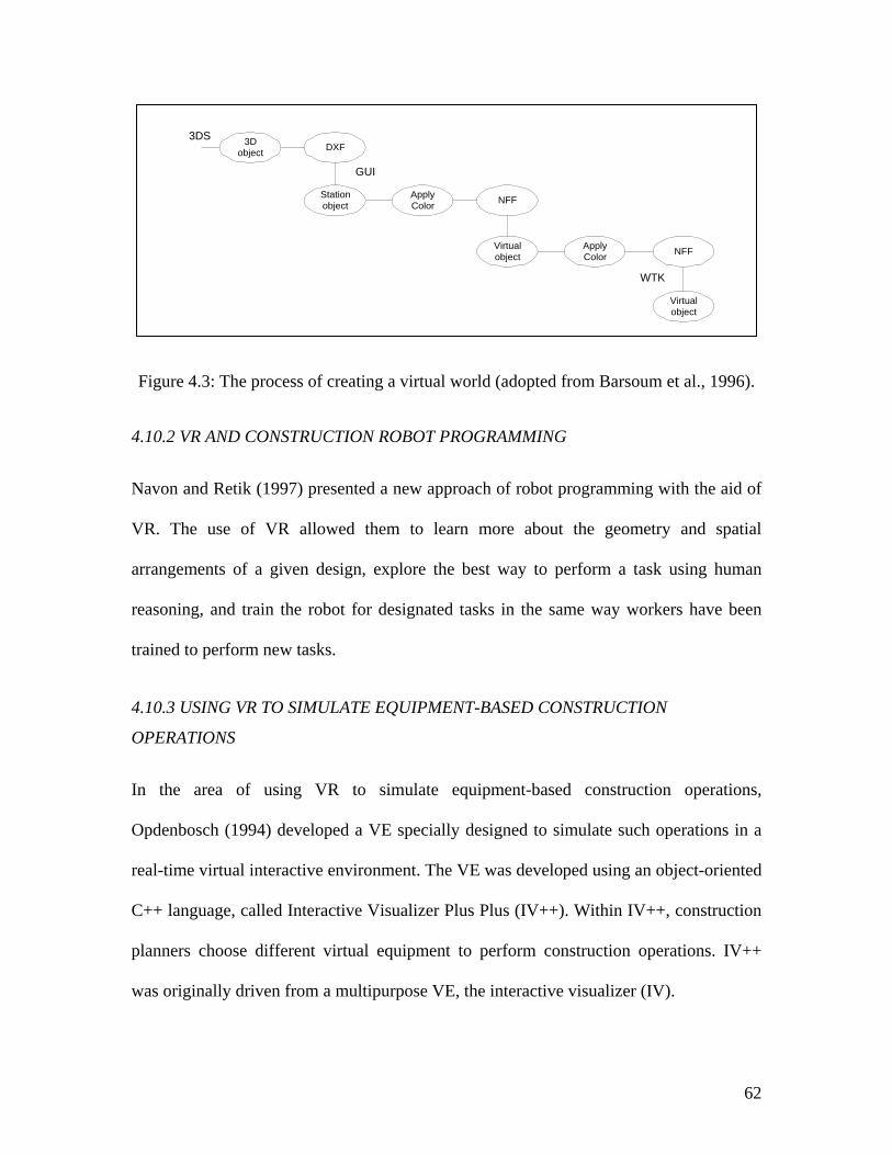
62
Figure 4.3: The process of creating a virtual world (adopted from Barsoum et al., 1996).
4.10.2 VR AND CONSTRUCTION ROBOT PROGRAMMING
Navon and Retik (1997) presented a new approach of robot programming with the aid of
VR. The use of VR allowed them to learn more about the geometry and spatial
arrangements of a given design, explore the best way to perform a task using human
reasoning, and train the robot for designated tasks in the same way workers have been
trained to perform new tasks.
4.10.3 USING VR TO SIMULATE EQUIPMENT-BASED CONSTRUCTION
OPERATIONS
In the area of using VR to simulate equipment-based construction operations,
Opdenbosch (1994) developed a VE specially designed to simulate such operations in a
real-time virtual interactive environment. The VE was developed using an object-oriented
C++ language, called Interactive Visualizer Plus Plus (IV++). Within IV++, construction
planners choose different virtual equipment to perform construction operations. IV++
was originally driven from a multipurpose VE, the interactive visualizer (IV).
3Dobject DXF
Stationobject
ApplyColor NFF
Virtualobject
ApplyColor NFF
Virtualobject
WTK
GUI
3DS
63
Opdenbosch (1994) also developed a new technique, Computer Aided Design and
Assembly (CADA), to simplify the process of defining assembly simulation goals by
using CAD. The goals are contained in the building model (BO), which is created using
CADA. BO is a building object definition file that contains the assembly sequences and
machine instructions to be rendered in the VE. The interface between the building model
components and the virtual equipment is called the planner. The planner takes care of
generating the sequence of instructions, using the available resources, to complete an
assembly goal. The sequences are determined by the order in which building components
are scheduled to appear in the environment.
There are three types of data associated with CADA:
1. The geometric information associated with the building primitives. A standard
building primitives data file includes the geometry, action, material, initial location,
initial orientation, coordinates, and color.
2. The hierarchical information that establishes the relationship between the building
components. The hierarchy is determined by the dependency that exists between
components. An example is shown in Figure 4.4.
3. Priority information, which is used to ensure that preconditions of a procedure are
fulfilled.
The methodology of simulating the construction of a building consists of the following
five steps (Opdenbosch, 1994):
• Design the building using CADA.
• Run the simulation with all the relevant elements such as cameras and lights.
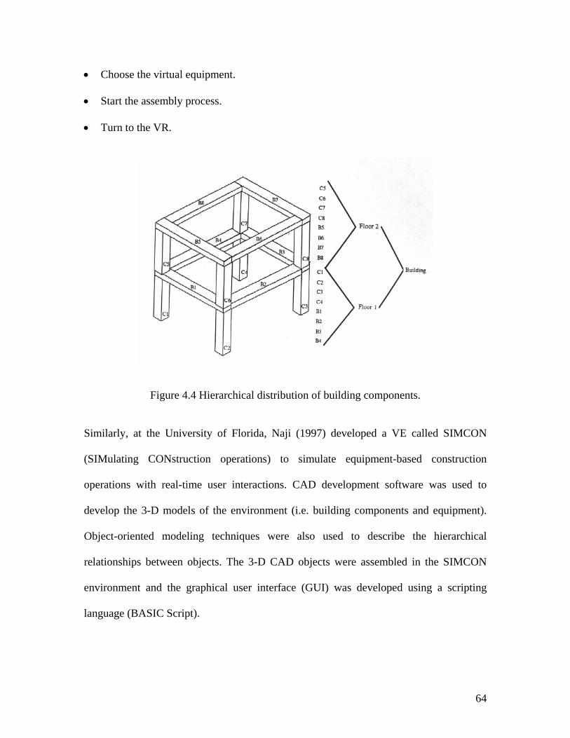
64
• Choose the virtual equipment.
• Start the assembly process.
• Turn to the VR.
Figure 4.4 Hierarchical distribution of building components.
Similarly, at the University of Florida, Naji (1997) developed a VE called SIMCON
(SIMulating CONstruction operations) to simulate equipment-based construction
operations with real-time user interactions. CAD development software was used to
develop the 3-D models of the environment (i.e. building components and equipment).
Object-oriented modeling techniques were also used to describe the hierarchical
relationships between objects. The 3-D CAD objects were assembled in the SIMCON
environment and the graphical user interface (GUI) was developed using a scripting
language (BASIC Script).
65
OpdenBosch (1994) and Naji (1997) introduced new ways of modeling equipment-based
construction operations using 3-D graphical output representations in real-time VE. In
their work, they focused on modeling the equipment-based construction operations in
specific and the building components and site in general. IV++ and SIMCON are
valuable examples of how a VE can be employed for construction simulation using
supercomputers and personal computers. However, a more in-depth study is needed in the
areas of physically-based modeling techniques, task-oriented modeling techniques, and
modeling of building components during construction (Hendrickson and Rehak, 1993,
Everett, 1991, AbouRizk et al., 1992).
4.10.4 VIRTUAL REALITY MODELING IN CONSTRUCTION
Tsay et al. (1996) developed a VR model of a bridge construction. The model allows the
construction engineers to interact virtually within the model using input devices to move
objects, connect and erect steel girders, and cast concrete for the bridge deck. The
development process of the environment consisted of three phases:
1. 3D-object modeling, AutoCAD and 3D Studio was used to create the 3D objects.
2. Programming an interactive construction site, the C language library from “Sense 8”
was used to develop the virtual model.
3. Incorporating tracking devices into the system.
This system can be categorized as a tool to train construction engineers to adequately
construct a bridge superstructure.
66
4.10.5 VIRTUAL CONSTRUCTION SITE
Hendrickson and Rehak (1993) speculated the idea of using a computer-based “virtual
construction site” (VCS) model to investigate alternative designs for sensing, site
modeling, distribution processing, and automation on construction sites. Also, they
discussed the importance of implementing physically-based modeling to achieve realistic
representation and assessment of automation and process design alternatives.
The benefits of developing a VCS model as Hendrickson and Rehak (1993) point out are:
• VCS models would represent an example of the next generation of CAD systems in
which engineering information could be accurately simulated.
• VCS models could be adopted for site logistics planning, in which the planner could
“move” equipment and the feedback would reflect cost and time implications of the
selections.
• VCS models might be useful in the design and selection of hazardous site remediation
strategies.
4.11 4D-CAD MODELING IN DESIGN AND CONSTRUCTION
4.11.1 INTRODUCTION
4D models integrate 3D CAD models with construction activities to display step-by-step
sequence of construction over time. This integration is accomplished through a third-
party knowledge-based system capable of integrating graphical and non-graphical
information. One of the earliest systems to use CAD technology for the purpose of
planning, scheduling, and controlling the construction process was developed by Bechtel
67
Western Power Co. and Bechtel Construction Inc. (Morad, 1990). This system combines
intelligent 3D CAD models, state of the art computer graphics capabilities, knowledge-
based decision support features, and a CPM schedule processor to display the progression
of construction over time.
Similarly, Stone and Webster Engineering Corp. (Morad 1990) developed a computerized
database system to integrate graphics, engineering data, and all other information
necessary for the engineering, design, construction, operation, and management of
facility.
Later, research has been carried out to integrate 4D with product model tools to improve
the quality of interdisciplinary collaboration. The product model and fourth dimension
(PM4D) approach represents such efforts (Fischer et al., 2002, VTT, 2003). For instance,
it has been used during the design and construction of the HUT-600 in Finland. The
PM4D approach was used to construct and maintain object-oriented product models of
building components, spatial definitions, material composition, and other parametric
properties. The product models used in this approach are based on open industry
foundation classes (IFC), which improved data and information exchange between the
project participants and their tools.
4.11.2 RESEARCH AT VIRGINIA TECH
Research at Virginia Tech was done to develop a CAD-based construction system
(Skolnick, 1990). The outcome of this research is the KNOW-PLAN and VSS systems.
KNOW-PLAN is a knowledge-based system that integrates artificial intelligence
technology with computer aided design technology to generate and simulate the
68
construction schedule of activities (Morad and Beliveau, 1990). The KNOW-PLAN
system generates a schedule of construction activities based on knowledge extracted from
3D computer models as well as other knowledge sources. The system visually simulates
the construction based on the generated sequence of activities. It allows the user to view
the step-by-step sequence of construction using the 3D computer model of the designed
facility.
VSS is a visual schedule simulation system developed at Virginia Tech. VSS is a system
that integrates traditional computer-based scheduling techniques with 3D CAD computer
modeling to provide a visual simulation of the construction sequence (Skolnick, 1990 and
Skolnick et al., 1990). The VSS system consists of three primary phases. Phase I is the
date preprocessor, which consists of preparing the CPM schedule (Primavera Project
Planner) and 3D computer model (CADAM) for a construction project. Phase II is the
database manager (dBASE IV), which maps the activities in the CPM schedule to each
object in the 3D computer model. Phase III is the visual simulator, which uses a
computer-based 3D simulation and visualization system (WALKTHRU).
4.11.3 RESEARCH AT BECHTEL CORPORATION
Bechtel Corporation has developed a planning graphical simulation tool called 4D-
Planner (4DP) that allows project managers and construction planners to create
interactive project simulations (Williams, 1996). The purpose of 4DP is to link the 3D
CAD model components to the associated network schedule activities. Williams (1996)
gives a detailed description of the 4DP and how it can be used as a visualization,
simulation, and communication tool.
69
The features of 4DP are the following:
• Provides simultaneous access to design and scheduling data.
• Provides a graphical simulation of the work plan.
• Allows early problem detection, including interference.
• Supports scenario analysis and “what-if” planning.
• Facilitates inter disciplinary constructability reviews.
• Helps optimize work plans and schedules.
• Provides a means to graphically represent the results for the planning process.
4.11.4 RESEARCH AT STANFORD UNIVERSITY
4D-CAD models (3D CAD plus time) are becoming more common in design and
construction (Fischer et al., 2002). 4D CAD models are currently being used as a
planning, communication and visualization tool. It allows the project participants to
simulate and visualize the sequence of the construction operations in time. Currently the
product model and fourth dimension (PM4D) research efforts have been carried out to
link product models with 4D-CAD models (Fischer et al., 2002). Such efforts have been
translated and tested during the design and construction of Helsinki University of
Technology Auditorium Hall 600 (HUT-600) project in Finland.
According to Fischer et al. (1996), “Conceptually 4D-CAD is a medium representing
time and space, a type of graphic simulation of a process. In construction, a 4D animation
simulates the process of transforming space over time and reflects the four-dimensional
nature of engineering and construction.”
70
In comparison to Bechtel’s 4DP, the fundamental purpose of 4D CAD models is to
produce 4D simulation by relating the 3D graphical model components (e.g. 3D CAD
models) with the construction network schedule activities (e.g. a schedule produced with
Primavera Planner). This can be achieved by importing the CAD model components and
the schedule into a third party simulation environment (e.g. PlantSpace). PlantSpace is a
suite of application products, which collectively function as a data integration application
(Jacobus Technology, 1997). Within the simulation environment, relationships between
the CAD model components and the schedule activities are created.
4.11.5 4D APPROACHES
As discussed earlier, 4D models integrate the 3D geometrical representation of the
building components with their corresponding scheduling data. The integration process
has resulted in the improvement of 4D modeling concepts and implementations. There
are several approaches for integration (VTT, 2003); however the two most developed and
promising approaches are the automation approach and the linking approach.
The automation approach refers to the generation of 4D models where a reasoning engine
or engines together with construction operations knowledge are able to interpret 3D
geometric data and produce visual simulation showing how the designed facility can be
constructed.
There are two categories of 4D CAD that fall under the automation approach: The first
category is visual 4D CAD and the second is collaborative 4D CAD. Visual 4D-CAD
succeeds in creating 4D animation by linking the construction schedule to the 3D-CAD
model components. Fischer et al. (1996) described the processes and the software
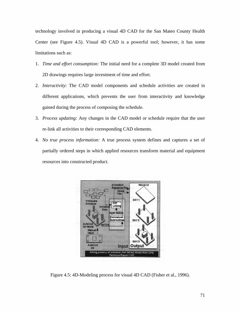
71
technology involved in producing a visual 4D CAD for the San Mateo County Health
Center (see Figure 4.5). Visual 4D CAD is a powerful tool; however, it has some
limitations such as:
1. Time and effort consumption: The initial need for a complete 3D model created from
2D drawings requires large investment of time and effort.
2. Interactivity: The CAD model components and schedule activities are created in
different applications, which prevents the user from interactivity and knowledge
gained during the process of composing the schedule.
3. Process updating: Any changes in the CAD model or schedule require that the user
re-link all activities to their corresponding CAD elements.
4. No true process information: A true process system defines and captures a set of
partially ordered steps in which applied resources transform material and equipment
resources into constructed product.
Figure 4.5: 4D-Modeling process for visual 4D CAD (Fisher et al., 1996).
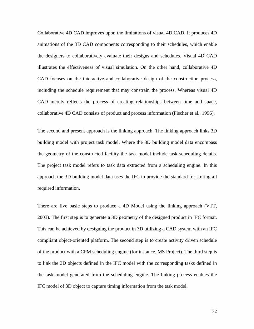
72
Collaborative 4D CAD improves upon the limitations of visual 4D CAD. It produces 4D
animations of the 3D CAD components corresponding to their schedules, which enable
the designers to collaboratively evaluate their designs and schedules. Visual 4D CAD
illustrates the effectiveness of visual simulation. On the other hand, collaborative 4D
CAD focuses on the interactive and collaborative design of the construction process,
including the schedule requirement that may constrain the process. Whereas visual 4D
CAD merely reflects the process of creating relationships between time and space,
collaborative 4D CAD consists of product and process information (Fischer et al., 1996).
The second and present approach is the linking approach. The linking approach links 3D
building model with project task model. Where the 3D building model data encompass
the geometry of the constructed facility the task model include task scheduling details.
The project task model refers to task data extracted from a scheduling engine. In this
approach the 3D building model data uses the IFC to provide the standard for storing all
required information.
There are five basic steps to produce a 4D Model using the linking approach (VTT,
2003). The first step is to generate a 3D geometry of the designed product in IFC format.
This can be achieved by designing the product in 3D utilizing a CAD system with an IFC
compliant object-oriented platform. The second step is to create activity driven schedule
of the product with a CPM scheduling engine (for instance, MS Project). The third step is
to link the 3D objects defined in the IFC model with the corresponding tasks defined in
the task model generated from the scheduling engine. The linking process enables the
IFC model of 3D object to capture timing information from the task model.
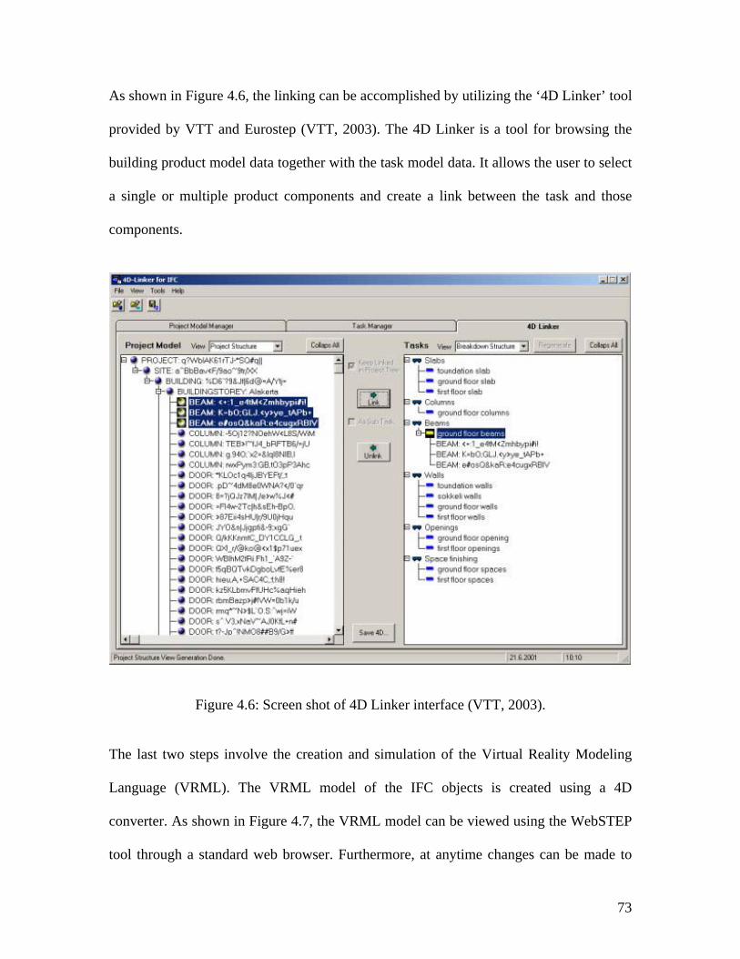
73
As shown in Figure 4.6, the linking can be accomplished by utilizing the ‘4D Linker’ tool
provided by VTT and Eurostep (VTT, 2003). The 4D Linker is a tool for browsing the
building product model data together with the task model data. It allows the user to select
a single or multiple product components and create a link between the task and those
components.
Figure 4.6: Screen shot of 4D Linker interface (VTT, 2003).
The last two steps involve the creation and simulation of the Virtual Reality Modeling
Language (VRML). The VRML model of the IFC objects is created using a 4D
converter. As shown in Figure 4.7, the VRML model can be viewed using the WebSTEP
tool through a standard web browser. Furthermore, at anytime changes can be made to
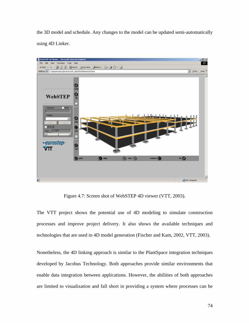
74
the 3D model and schedule. Any changes to the model can be updated semi-automatically
using 4D Linker.
Figure 4.7: Screen shot of WebSTEP 4D viewer (VTT, 2003).
The VTT project shows the potential use of 4D modeling to simulate construction
processes and improve project delivery. It also shows the available techniques and
technologies that are used in 4D model generation (Fischer and Kam, 2002, VTT, 2003).
Nonetheless, the 4D linking approach is similar to the PlantSpace integration techniques
developed by Jacobus Technology. Both approaches provide similar environments that
enable data integration between applications. However, the abilities of both approaches
are limited to visualization and fall short in providing a system where processes can be
75
modeled. In other words, the 4D visual modeling approaches don’t contain true process
information. The ability to model construction processes and capture the information
associated with them are essential to analyze and improve construction operations.
4.12 SYNOPSIS
Chapter Four reviews the fundamentals of virtual environments and the application of
virtual and 4D-CAD modeling approaches in construction. The advantages and
limitations of these approaches in relation to the developed modeling system in this
research are identified. Virtual environments are identified as excellent representation
medium for visualizing construction operations. Nonetheless, in addition to existing
virtual modeling environments and 4D-CAD approaches, a new improved modeling
system that has the ability to model, record and analyze construction operations is
needed.
76
CHAPTER FIVE: CONSTRUCTION AUTOMATION AND ROBOTICS TECHNOLOGIES
5.1 INTRODUCTION
This chapter reviews research conducted in the area of automated and robotic
technologies specifically developed for the construction industry. Also, this chapter
analyzes the distribution of work between humans, tools and equipment based on their
physical and information contributions. In the past decade, research and development of
construction automation and robotics has advanced rapidly to the point where many
technologies are close or in commercial use (Skibniewski et al., 1986, Navon, 1995, and
Slaughter, 1997).
Robots are used in construction operations; to improve safety of workers and eliminate
dangerous operations; to increase productivity; and to improve final quality (Kangari,
1988, Slaughter, 1997). Additionally, opportunities for construction automation can be
improved by analyzing human, equipment and construction operations to determine how
they interact among each other.
77
5.2 DEFINITION
A widely accepted definition by Robotics Industry Association characterizes robot as
reprogrammable multifunctional manipulator designed to move material, parts, tools, and
specialized devices through variable programmed motions for the performance of a
variety of tasks (Slaughter, 1997). Nevertheless, this definition is inadequate for
construction robots. Whittaker and Bandari (1986) simply characterize construction
robots as “robots that can constructs, meaning builds, and yet such robots do a lot more;
they exhibit flexibility in the roles they play and the equipment they use, and they
perform tasks of a complexity that previously required human control.” Furthermore,
automation is a combination of man and machine, while robotization is machine only
(Everett, 1991).
5.3 TYPES OF ROBOTS
In general, robots can be classified into three categories: teleoperated robots,
programmed robots, and cognitive robots. Each distinguished by the control procedures
available to the robot and its relationship to human supervisors (Whittaker and Bandari,
1986). Teleoperated robots, includes machines where humans control all planning,
perception, and manipulation. Further, teleoperation is evolving robot forms and bodies
suited to unstructured tasks and environments. Programmed robots, in this category robot
perform predictable, invariant tasks according to pre-programmed instructions. While
programmed robots are the backbone of manufacturing, it has limited use in construction.
This is because this type of robots is suitable for predictable and invariant tasks, whereas
construction robot must be able to recognize and responds to unknowns and unplanned
78
difficulties. Cognitive robots can sense, model, plan and act to achieve goals in the
manner of teleoperators but without human supervisors (Whittaker and Bandari, 1986).
5.4 POTENTIAL USE OF ROBOTICS IN CONSTRUCTION
Everett (1991) proposes that the best opportunities for construction automation occur at
the basic task level. The basic tasks are: connect, cover, dig, finish, inspect, measure,
place, position, spray, and spread. An earlier statistical study by Kangari and Halpin
(1989) justifies that basic tasks are more suitable for automation than activities.
Kangari and Halpin (1989) examine the potential use of robotics in construction. Their
study analyzes thirty-three construction processes based on three major criteria and
several sub-criteria for each of them. Three major criteria are identified: need based
feasibility, technical feasibility, and economic feasibility. Need consists of ten sub-
criteria: labor intensiveness, vanishing skills, requires high skills, dexterity and precision,
repetitiveness, tedious and boring, critical to productivity hazards, and physically
hazardous. Five sub-criteria of technology are identified: material handling requires
sensors, control software, control hardware, and end effector. Economics include three
sub-criteria: productivity improvement, quality improvement, and saving in labor.
For each construction process, a normalized rating on a scale of one to ten was assigned
for each sub-criterion of the three major criteria, with ten indicating the highest feasibility
for robotization. Normalized weighted average was then calculated for each criterion.
Kangari and Halpin’s thirty-three construction processes and the corresponding
normalized weighted averages for the three major criteria are shown in Table 5.1. For
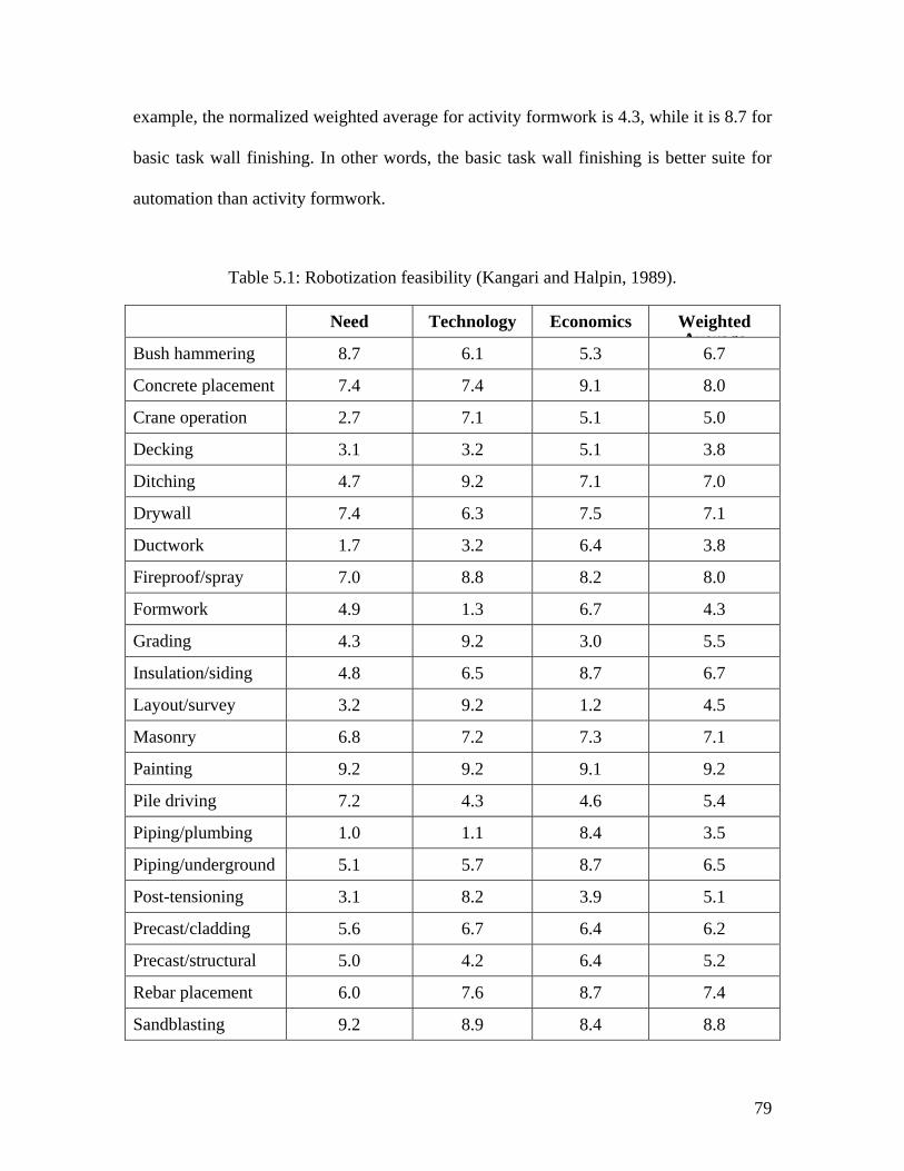
79
example, the normalized weighted average for activity formwork is 4.3, while it is 8.7 for
basic task wall finishing. In other words, the basic task wall finishing is better suite for
automation than activity formwork.
Table 5.1: Robotization feasibility (Kangari and Halpin, 1989).
Need Technology Economics Weighted Average
Bush hammering 8.7 6.1 5.3 6.7
Concrete placement 7.4 7.4 9.1 8.0
Crane operation 2.7 7.1 5.1 5.0
Decking 3.1 3.2 5.1 3.8
Ditching 4.7 9.2 7.1 7.0
Drywall 7.4 6.3 7.5 7.1
Ductwork 1.7 3.2 6.4 3.8
Fireproof/spray 7.0 8.8 8.2 8.0
Formwork 4.9 1.3 6.7 4.3
Grading 4.3 9.2 3.0 5.5
Insulation/siding 4.8 6.5 8.7 6.7
Layout/survey 3.2 9.2 1.2 4.5
Masonry 6.8 7.2 7.3 7.1
Painting 9.2 9.2 9.1 9.2
Pile driving 7.2 4.3 4.6 5.4
Piping/plumbing 1.0 1.1 8.4 3.5
Piping/underground 5.1 5.7 8.7 6.5
Post-tensioning 3.1 8.2 3.9 5.1
Precast/cladding 5.6 6.7 6.4 6.2
Precast/structural 5.0 4.2 6.4 5.2
Rebar placement 6.0 7.6 8.7 7.4
Sandblasting 9.2 8.9 8.4 8.8
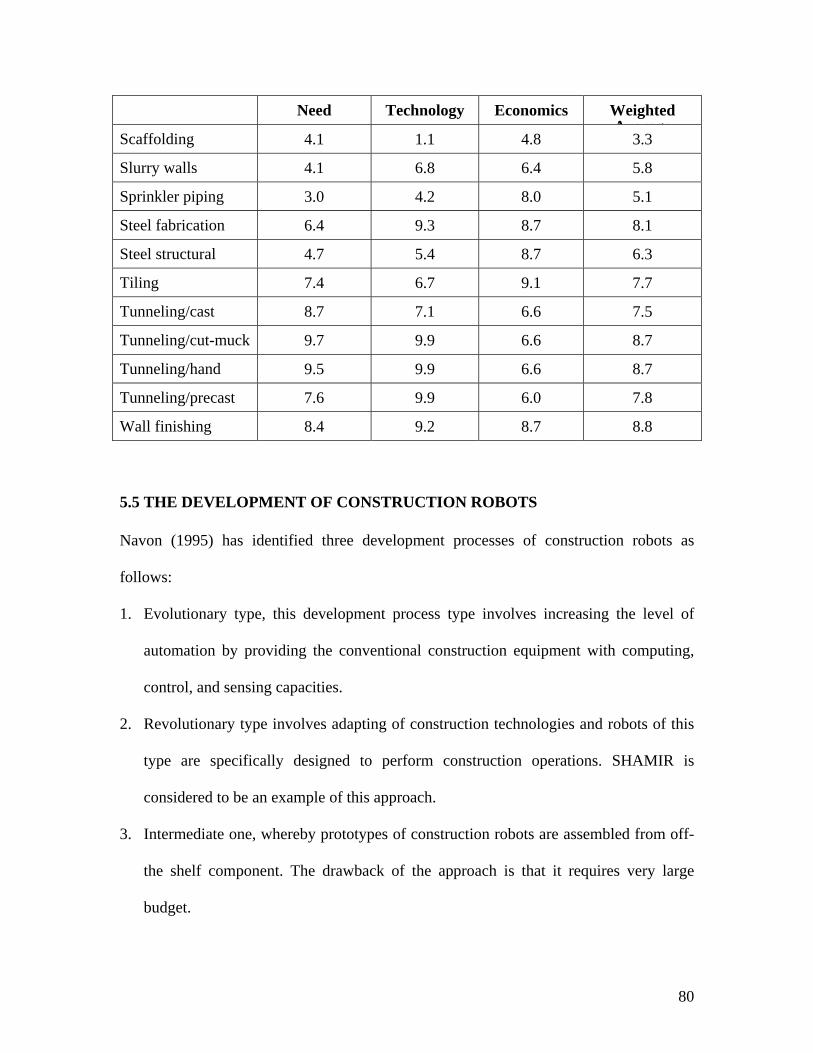
80
Need Technology Economics Weighted Average
Scaffolding 4.1 1.1 4.8 3.3
Slurry walls 4.1 6.8 6.4 5.8
Sprinkler piping 3.0 4.2 8.0 5.1
Steel fabrication 6.4 9.3 8.7 8.1
Steel structural 4.7 5.4 8.7 6.3
Tiling 7.4 6.7 9.1 7.7
Tunneling/cast 8.7 7.1 6.6 7.5
Tunneling/cut-muck 9.7 9.9 6.6 8.7
Tunneling/hand 9.5 9.9 6.6 8.7
Tunneling/precast 7.6 9.9 6.0 7.8
Wall finishing 8.4 9.2 8.7 8.8
5.5 THE DEVELOPMENT OF CONSTRUCTION ROBOTS
Navon (1995) has identified three development processes of construction robots as
follows:
1. Evolutionary type, this development process type involves increasing the level of
automation by providing the conventional construction equipment with computing,
control, and sensing capacities.
2. Revolutionary type involves adapting of construction technologies and robots of this
type are specifically designed to perform construction operations. SHAMIR is
considered to be an example of this approach.
3. Intermediate one, whereby prototypes of construction robots are assembled from off-
the shelf component. The drawback of the approach is that it requires very large
budget.
81
Navon (1995) describes a methodology used for the development of the Surface
Horizontal Autonomous Multipurpose Interior Robot (SHAMIR). SHAMIR is designed
to perform the major activities. First, horizontal surface treatment such as, grinding
concrete, cleaning floors with a vacuum, and finishing concrete floors. Second, floor
covering such as, tile setting, covering floors with carpet, and coating floors with liquid
materials. Third, sealing joints between prefabricated slabs or between tiles. Finally,
general assignments for example, quality control task and service tasks.
Navon’s methodology is divided into five stages: performance specifications, conceptual
design, computer-graphic-based testing, detailed design, and construction of a prototype.
Navon’s introduced and integrated the graphic-simulation-based process to the traditional
development practices of construction robots. The graphic simulation stage permits the
analysis of parameters as early as the conceptual design stage. This analysis is normally
associated with the detailed stage. The five stages of Navon’s methodology are as follow:
1. Performance specification, which refer to the activities to be performed by the robot,
the material supply system for each activity, the method of execution, the definition
of the working environment, etc. Also, it determines the requirements to be
accomplished by the robot based on the proposed construction technologies.
2. Conceptual design, where the robot is designed conceptually in order to check if the
performance specifications can be reached.
3. Experiments using computer-graphics simulation. This stage is unique to the
proposed development process as it facilitates the testing of the alternatives needed to
optimize SHAMIR’s selected parameters. It has the three following objectives:
• To perform functional feasibility tests of the various suggested systems.
82
• To compare the performance of alternative systems
• To determine the optimal values of the robot’s parameters
4. Detailed design
5. Prototype construction
SHAMIR is designed as a multipurpose robot to operate inside large halls. As an
implementation of SHAMIR, a construction technology, terrazzo tile floor was simplified
at the conceptual stage. The conventional method of terrazzo tile flooring consists of
spreading sand, spreading mortar, and setting the tiles. The proposed solution is to set the
tiles directly on the top of the concrete floor, using bonding materials such as glue. The
modification in the construction technology resulted in simplifying the conceptual design
of the SHAMIR.
5.6 COMPLEXITY AND RECOMMENDATIONS IN CONSTRUCTION ROBOTS DESIGN
There are several ways of designing construction robots. One approach to accomplish a
robot design is to mimic a human worker without any change in the manual construction
technology (Navon, 1995). This approach is typical to robot developers who are not
familiar enough with construction technologies. For example, a masonry robot that lays
the bricks and bonds them with mortar. There are two disadvantages of this approach.
First, the robot will most likely be too complex. Second, the cost of such robot will
probably be unjustified. Another approach is to modify a construction technology so it
can be performed with minimum changes to commercially available robots. Likewise
83
mimicking human workers, this approach may be costly because the changes to
construction technology may involve very expensive solutions.
An intermediate approach is to bring construction and robotics technologies closer
together (Navon 1995, Slaughter, 1997). This approach will require changes to robot
design and the way we do construction today. Successful changes may result of valuable
implementation of robotics in construction. Moreover, design and construction processes
of a facility need to be connected in some way (Slaughter, 1997). This connection may
influence the acceptability of these technology applications during the design process.
Explicit analysis and the integration of either advanced construction technologies or
traditional methods within the earliest conceptual design stages of a facility, may lead to
new concepts of building systems and new structural systems. “New systems that are
designed with the ease of automation in mind may also improve aspects of the
construction process even without automation” (Slaughter, 1997)
5.7 A MAN-MACHINE-SYSTEM (A MOBILE BRICK LAYING ROBOT)
Pritschow et al. (1996) discusses the technological aspects involved in the development
of a mobile bricklaying robot. The tasks of mobile bricklaying mobile include picking
bricks from prepared pallets, the application of bonding material and the erection of
brickwork at high accuracy and quality. The proper function of the robot requires;
handling different sizes of brick, detection and compensation of material tolerances,
calibration o the brick position with respect to the tool center point, automated dispensing
of bonding material, and robust, site specific and cost-effective solutions.
84
Pritschow et al. (1996) developed a man-machine-system that enables automated onsite
construction of masonry. The system consisted of a mobile robot and skilled operator.
Unlike manual construction methods, onsite masonry construction requires additional
planning of the construction work to achieve automation. For example, the bricks need to
be pre-positioned in the planned location.
The site staff has to execute the following tasks before the actual construction:
• Plan the start location of the robot and the material.
• Supply the material.
• Erection of position reference points for the robot.
• Starting the robot.
During the construction operation the operator has the following tasks:
• To supervise the automatic construction process and correct errors that might
occur.
• To supply and test material.
• To manually complete the brickwork which the robot cannot perform.
Based in a program-controlled manner, the robot can perform the following operation:
• Automated maneuvering.
• To determine the exact position using sensors.
• To locate the pallet position.
• To identify the bricks as well as pick up from the pallet.
• To apply mortar.
85
• Automatic positioning of the bricks with the desired accuracy.
5.8 RESEARCH AT NORTH CAROLINA STATE UNIVERSITY
Moon and Bernold (1997) developed the robotic bridge paint removal (RBPR) system at
the construction automation and robotics laboratory at North Carolina State University.
RBPR system was developed based on a telerobotic operation as an alternative to
conventional bridge paint removal methods. This system also was developed as a safe
alternative method to increase the safety of the workers and to protect the natural
environment against toxic pollution. Telerobotic approach frees the workers from
exposure to the toxic lead paint by separating the workers at a control station from the
operational mechanism at the work area.
The telerobotic operation of bridge paint removal uses two control strategies to
accomplish the necessary tasks to remove the paint. The first strategy is to visually
inspect the steel beam surface, define the corroded area, and to setup and position the
RBPR under the bridge. This operation is controlled manually by a human operator using
a joystick and with the aid of a visual live image from a camera and a sensory data. The
second strategy is to perform the actual paint removal work using the end-effector
positioned at a desired location. This strategy involves generating an automatic motion
path for the robot arm to spot- clean the paint. Subsequently, the robot arm moves to the
required position and performs the operation.
“By regulating the dynamic interaction between the operator and the robot controller,
supervisory control permits performance that either autonomous controller or human
86
operator alone would be able to achieve” (Moon and Bernold, 1997). The developed
telerobotic RBPR demonstrates that the manual control capability is of great importance
for tasks that have high complexity. The control of the RBPR system keeps the human
operator as a supervisory integral part of the overall control system.
5.9 CONSTRUCTION PROCESS SIMULATION WITH RULE-BASED ROBOT PATH PLANNING
Stouffs et al. (1994) developed a rule-based simulation program (RUBICON) for
application to building construction. The RUBICON simulator requires a specified task
schedule to generate and simulate a motion path for each robot action, avoiding obstacles,
safety, and other considerations (see Figure 5.1).
The input to the RUBICON program consists of two kinds of files:
1. The task plan file consisting of:
• Description of the construction elements.
• The construction process as a sequence of tasks. Tasks either performed by
human or robot crew. A typical robot task may be: “Move Wall Panel Mark 1,
Floor 1, and Part #5 (WALL-PANEL-1.15) from truck site (0.0, -4.0, 2.0) to
position x-y-z (54.4, 6.6, 1.2) with the Robot overhead Crane. Estimated time is
0.16” Stouffs et al., 1994).
2. The motion file, consisting of:
• Description of the motional capabilities of the robots characterized by their ability
to lift, move, and place construction elements from a fixed location to a placement
location.
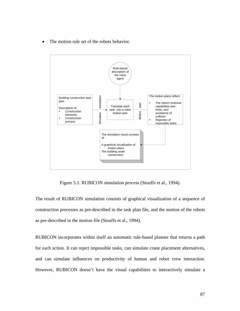
87
• The motion rule set of the robots behavior.
Building construction taskplan
Description of:ConstructionelementsConstructionprocess
Rule-baseddescription of
the robotagent
The motion plans reflect:
The robot's motionalcapabilities andlimits, andavoidance ofcollisionRejection ofimpossible tasks
Translate eachtask into a robot
motion plan
The simulation result consistsof:
A graphical visualization ofmotion plans
The building underconstruction
Sim
ulat
or
tra
nsla
tion
Mot
ion
pl
an
Figure 5.1: RUBICON simulation process (Stouffs et al., 1994).
The result of RUBICON simulation consists of graphical visualization of a sequence of
construction processes as pre-described in the task plan file, and the motion of the robots
as pre-described in the motion file (Stouffs et al., 1994).
RUBICON incorporates within itself an automatic rule-based planner that returns a path
for each action. It can reject impossible tasks, can simulate crane placement alternatives,
and can simulate influences on productivity of human and robot crew interaction.
However, RUBICON doesn’t have the visual capabilities to interactively simulate a
88
construction process because it is based on predefining the construction process and the
corresponding tasks prior to running the simulation. Interactivity here refers to the user’s
ability to visually execute construction tasks with simultaneous feedback.
5.10 HUMAN, TOOLS AND EQUIPMENT
5.10.1 DIVISION OF WORK BETWEEN HUMAN AND EQUIPMENT
To take human, tools and equipment into a common taxonomy, it is first necessary to
analyze human, equipment, and work tasks to determine how they interact among each
other. This section reviews the division of work between human and equipment. Given
that the goal of work division is to enable modeling and improving construction
operations, it is important to examine carefully what type of work human should do and
when machine might be chosen instead. This will require exploiting the abilities of both
human and equipment.
As shown in Table 5.2, Singleton (1974) outlined some characteristics that distinguish
human performance from that of machines on a number of functions. Depending on the
task, it is sometimes better to use equipment than human. Equipment is obviously good at
tasks requiring power, speed, and computing. Moreover, equipment is much better than
human in handling tasks that require extensive physical work, and can sometimes handle
the information processing work.
Table 5.2 also shows that humans are superior at information intensive operations such as
adapting, judging, and sensing, while machines are better at physical, repetitive
operations. Furthermore, as a step toward improvement of construction operation,
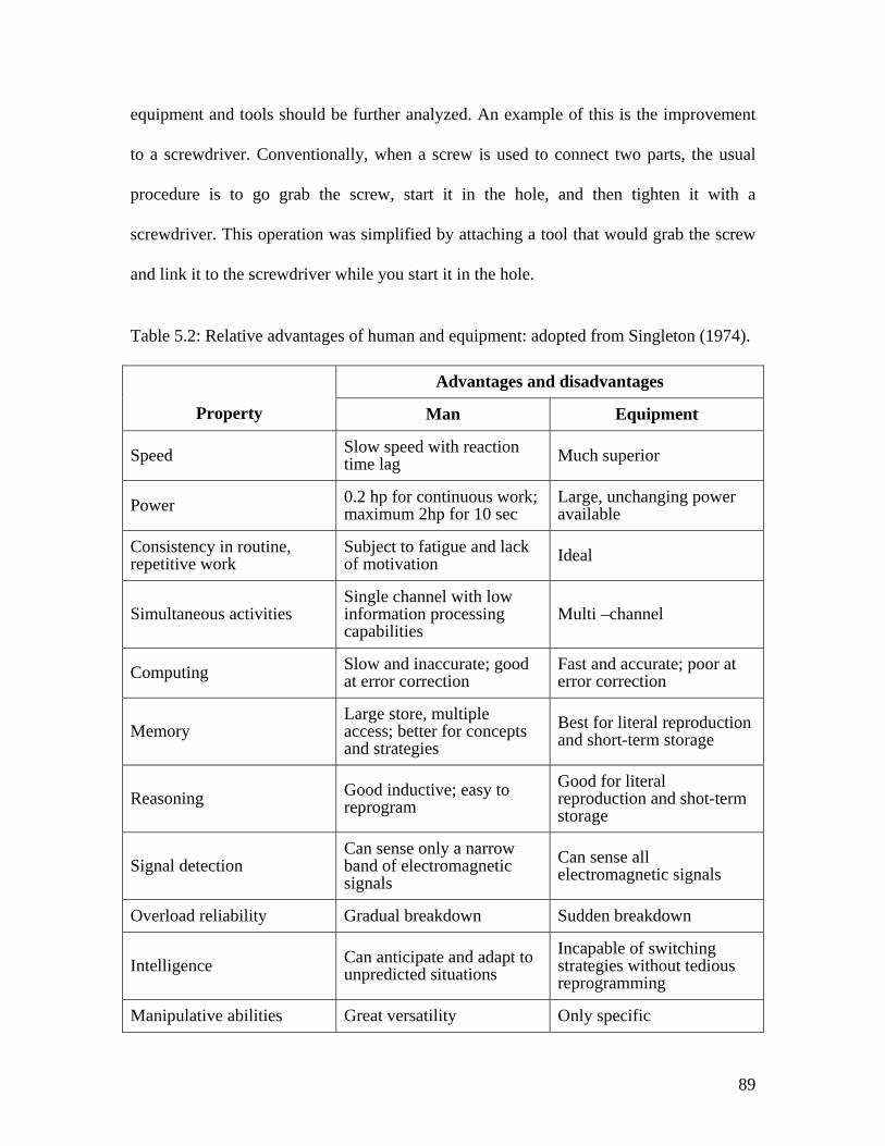
89
equipment and tools should be further analyzed. An example of this is the improvement
to a screwdriver. Conventionally, when a screw is used to connect two parts, the usual
procedure is to go grab the screw, start it in the hole, and then tighten it with a
screwdriver. This operation was simplified by attaching a tool that would grab the screw
and link it to the screwdriver while you start it in the hole.
Table 5.2: Relative advantages of human and equipment: adopted from Singleton (1974).
Advantages and disadvantages
Property Man Equipment
Speed Slow speed with reaction time lag Much superior
Power 0.2 hp for continuous work; maximum 2hp for 10 sec
Large, unchanging power available
Consistency in routine, repetitive work
Subject to fatigue and lack of motivation Ideal
Simultaneous activities Single channel with low information processing capabilities
Multi –channel
Computing Slow and inaccurate; good at error correction
Fast and accurate; poor at error correction
Memory Large store, multiple access; better for concepts and strategies
Best for literal reproduction and short-term storage
Reasoning Good inductive; easy to reprogram
Good for literal reproduction and shot-term storage
Signal detection Can sense only a narrow band of electromagnetic signals
Can sense all electromagnetic signals
Overload reliability Gradual breakdown Sudden breakdown
Intelligence Can anticipate and adapt to unpredicted situations
Incapable of switching strategies without tedious reprogramming
Manipulative abilities Great versatility Only specific
90
5.10.2 HUMAN
In construction humans control and supply most of the information processing
component and some of the physical component. The physical capacity of construction
workers varies from one to another due to differences in the workers’ age, sex, health,
and physical fitness. For example, when two skilled masons perform a brick laying
operation, an older or physically unfit mason will find the operation more difficult
physically than a younger or physically fit mason. Furthermore, the production of
construction workers is often increased by the introduction of power-driven devices: for
example, a power saw in place of handsaw.
A human usually does three things in performing any task: (1) receives information, (2)
makes decisions, and (3) take actions. Information is received through his sense organs
(ears, eyes, touch, etc…). Then decisions are made based on the obtained information and
previous human knowledge. Decisions are then translated into actions. Actions may be
purely physical or it may involve communication action (oral or written).
The first scientific efforts to apply human factors engineering to construction work is by
Gilbreth in 1917 (Helander, 1981) who was originally a contractor, and applied the
science of time and motion studies to masonry. He found that mason productivity could
be increased by setting size and weight standards for bricks, and by limiting the height
they should be lifted. Furthermore, design of workplaces and work methods seek to
determine the most effective combination of the man, machine and the working
environment. This could be achieved by determining which activities human can better
perform and when machines are used instead. Also, by deciding how human or/and
91
machines will do it. As listed in Tables 5.2, machines have certain abilities, which
surpass human, whereas human excels machines in certain ways.
5.10.3 CONSTRUCTION EQUIPMENT AND TOOLS
Based on the distribution of physical and information processes components between
human and equipment, construction equipment can be classified as: Hand tools, power-
driven devices, assisted manual controlled devices, and tele-operated devices.
5.10.4 HAND TOOLS
Hand tools is the first category where both the physical (force and energy) and
information components (i.e., when to start and end a task) are completely supplied by
human. Hand tools do not supply any energy or information feedback. Hand tools are
used to enable humans to exert a force greater than could be exerted by using muscles
alone or to apply force more efficiently. Generally, manual hand tools require great
human effort to use. Examples of hand tools are screwdrivers, spanners and wrenches,
hammers, drill bits, clamps, measuring tapes, brushes, plumbing tools, and chisels. Also
as shown in Table 5.3, hand tools extend the capability of the hand such as more grip
strength, powerful impact strength, etc.
Hand tools are based on the four simple machines, where a machine is a device used to
change the magnitude or direction of an applied force. The four simple machines are the
lever, the pulley, the wheel and axle, and the inclined plane, as shown in Table 5.4. The
screw and the wedge are also usually considered simple machines, but they are in
substance adaptations of the inclined plane.
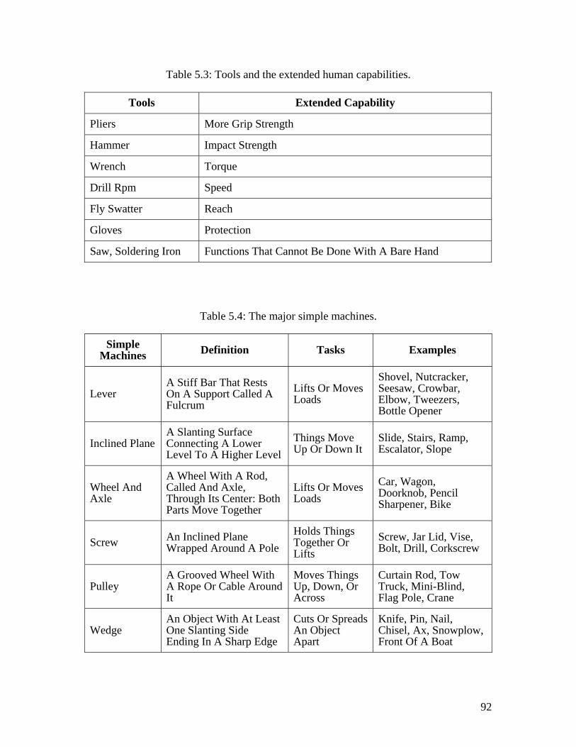
92
Table 5.3: Tools and the extended human capabilities.
Tools Extended Capability
Pliers More Grip Strength
Hammer Impact Strength
Wrench Torque
Drill Rpm Speed
Fly Swatter Reach
Gloves Protection
Saw, Soldering Iron Functions That Cannot Be Done With A Bare Hand
Table 5.4: The major simple machines.
Simple Machines Definition Tasks Examples
Lever A Stiff Bar That Rests On A Support Called A Fulcrum
Lifts Or Moves Loads
Shovel, Nutcracker, Seesaw, Crowbar, Elbow, Tweezers, Bottle Opener
Inclined Plane A Slanting Surface Connecting A Lower Level To A Higher Level
Things Move Up Or Down It
Slide, Stairs, Ramp, Escalator, Slope
Wheel And Axle
A Wheel With A Rod, Called And Axle, Through Its Center: Both Parts Move Together
Lifts Or Moves Loads
Car, Wagon, Doorknob, Pencil Sharpener, Bike
Screw An Inclined Plane Wrapped Around A Pole
Holds Things Together Or Lifts
Screw, Jar Lid, Vise, Bolt, Drill, Corkscrew
Pulley A Grooved Wheel With A Rope Or Cable Around It
Moves Things Up, Down, Or Across
Curtain Rod, Tow Truck, Mini-Blind, Flag Pole, Crane
Wedge An Object With At Least One Slanting Side Ending In A Sharp Edge
Cuts Or Spreads An Object Apart
Knife, Pin, Nail, Chisel, Ax, Snowplow, Front Of A Boat
93
When using hand tools, work is usually composed of three steps: get ready (search,
select, grasp, and move), do the work, and put away (release). Based on the level of
specialization, hand tools are two types: special purpose tools and multifunction tools.
Special purpose tools are best for work that is repeated hundred of times, where
multifunction tools, two tools in one, may eliminate processes such as reach, grasp,
move, and release from the labor time. Furthermore, multifunction tools also may save
the get ready and put away time. For example, a claw hammer combines a hammer and
nail claw; a pliers combines a gripper and a wire cutter.
5.10.5 POWER-DRIVEN DEVICES
In this category, the machine provides some or the entire physical component to perform
the work, while the human supplies some of the physical component and the all the
information-processing component. An example of power-driven devices is an electric
drill. The drill operator supplies some of the physical component by supporting the drill,
but the motor and the drill it self supplies most of the physical work. On the other hand,
the entire information-processing component is controlled and supplied by the operator.
The operator guides the drill and controls the when the drill starts and stops by pressing
the trigger. Likewise, a crane operator moving a steel beam from one location to the final
location controls all the information components, such as identifying the beam to be
moved, determining when to start and stop swinging the boom; and finally where to
position/place the beam. In addition, the operator contributes partially to the physical
component by using the crane controllers. In the aforementioned operation, the crane
provides most of the physical component, such as lifting the beam, and moving the beam
according to the operator’s input. Examples of power driven devices are powered-driven
94
saws (i.e., reciprocating, circular, and band sawing), earth-moving machines (i.e.,
scrapers, graders, bulldozers, and power shovels), and cranes (i.e., jib crane, derrick
crane, and bridge carne).
5.10.6 ASSISTED MANUALLY CONTROLLED DEVICES
This category provides most of the physical component and some of the information-
processing component to perform the work. Still the operator controls some or most of
the information-processing component. Examples of assisted manually controlled devices
are laser directed graders, load monitor on cranes, and automatic transmissions. Laser
directed graders relieve the operator from lowering and raising the blade as the laser
check the level of the blades as required.
5.10.7 TELE-OPERATED DEVICES
Similar to the assisted manually controlled devices, this category supplies all the physical
work and some of the information processing input while human supplies most of the
information processing input and doesn’t contribute to the physical component.
Televisions, videocassette recorders, and motion sensing cameras are examples of the
tele-operated technology.
5.10.8 THE DISTRIBUTION OF PHYSICAL AND INFORMATION PROCESSING
COMPONENTS BETWEEN HUMAN AND EQUIPMENT
Every productive construction operation that involves the use of human and equipment
imposes both physical and an information component (Porter and Miller, 1985). The
physically-processing component includes all the physical tasks required to perform an
operation, such as force and energy. The information-processing component involves the
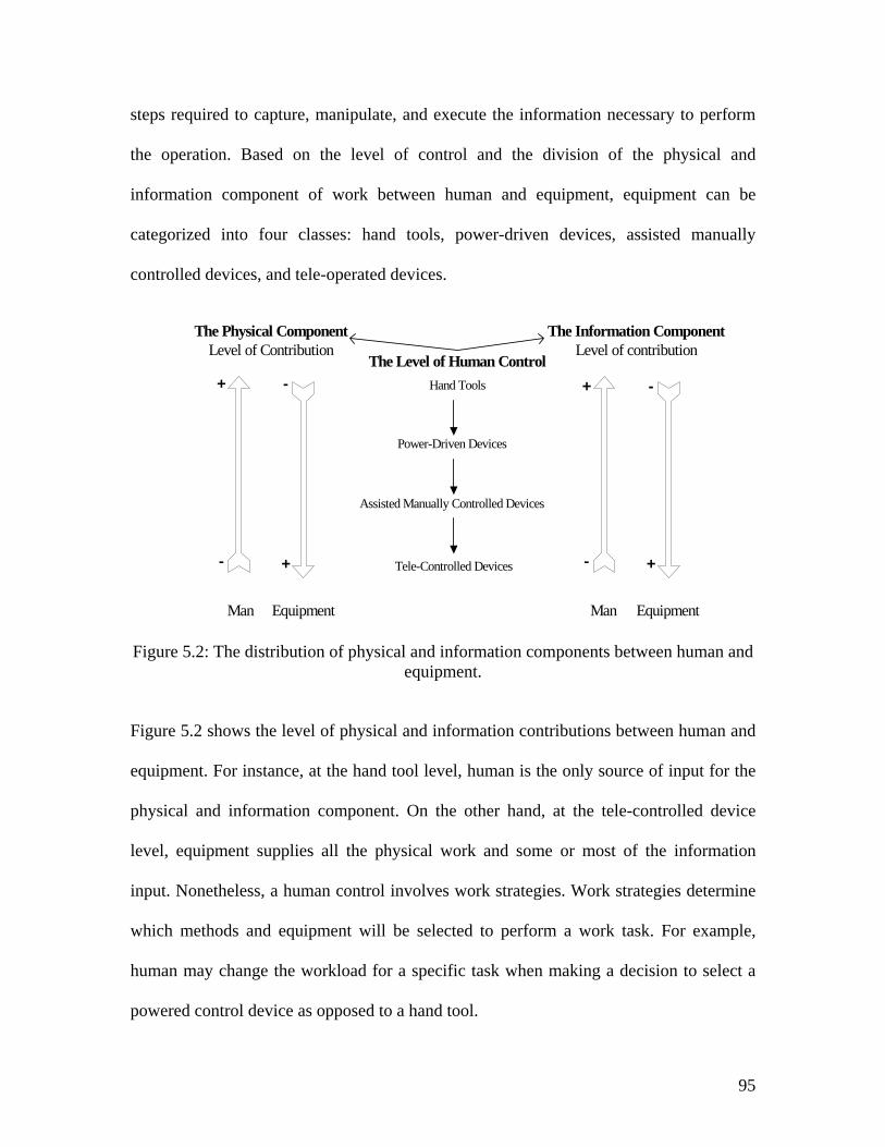
95
steps required to capture, manipulate, and execute the information necessary to perform
the operation. Based on the level of control and the division of the physical and
information component of work between human and equipment, equipment can be
categorized into four classes: hand tools, power-driven devices, assisted manually
controlled devices, and tele-operated devices.
Figure 5.2: The distribution of physical and information components between human and equipment.
Figure 5.2 shows the level of physical and information contributions between human and
equipment. For instance, at the hand tool level, human is the only source of input for the
physical and information component. On the other hand, at the tele-controlled device
level, equipment supplies all the physical work and some or most of the information
input. Nonetheless, a human control involves work strategies. Work strategies determine
which methods and equipment will be selected to perform a work task. For example,
human may change the workload for a specific task when making a decision to select a
powered control device as opposed to a hand tool.
Assisted Manually Controlled Devices
Hand Tools
Power-Driven Devices
Tele-Controlled Devices
Man Equipment
The Physical ComponentLevel of Contribution
The Information ComponentLevel of contribution
Man Equipment
The Level of Human Control+
+
+
+
-
-
-
-
96
5.11 SYNOPSIS
In this chapter, the potential uses of robotics and automation opportunities in construction
are discussed. Also, the distribution of work between humans and tools and equipment
based on their physical and information contributions are presented. The next chapter
presents and analyses the classification of construction work at different level of detail to
identify which construction operations can be usefully modeled and the appropriate level
of the model.
97
CHAPTER SIX: TASK IDENTIFICATION
6.1 INTRODUCTION
This chapter describes and analyzes construction work classifications at different levels
of detail. The analyses are focused on identifying construction operations that can be
usefully modeled and the appropriate level of the model. In addition, this chapter reviews
the product and process breakdowns in manufacturing operations.
Research in onsite construction operation processes has been actively carried out to
identify automation opportunities. Researchers such as Kangari and Halpin (1989),
Halpin and Riggs (1992), Basford and Askew (1992), and Everett (1994) have analyzed
automation opportunities at various levels of detail. These levels are the task, activity,
and division level. The main purpose of the analysis is to simplify the on site construction
work in order to identify construction tasks that can be automated and usefully modeled.
Most researchers have recognized the task level (i.e., connect, move, etc.) as the simplest
and most appropriate level for automation. On the other hand, the activity level, which
consists of several tasks, and the division level, which consists of several activities,
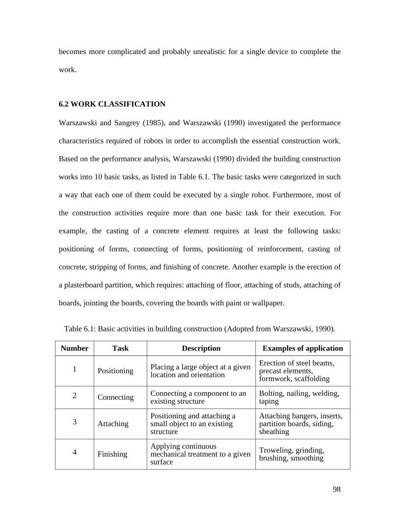
98
becomes more complicated and probably unrealistic for a single device to complete the
work.
6.2 WORK CLASSIFICATION
Warszawski and Sangrey (1985), and Warszawski (1990) investigated the performance
characteristics required of robots in order to accomplish the essential construction work.
Based on the performance analysis, Warszawski (1990) divided the building construction
works into 10 basic tasks, as listed in Table 6.1. The basic tasks were categorized in such
a way that each one of them could be executed by a single robot. Furthermore, most of
the construction activities require more than one basic task for their execution. For
example, the casting of a concrete element requires at least the following tasks:
positioning of forms, connecting of forms, positioning of reinforcement, casting of
concrete, stripping of forms, and finishing of concrete. Another example is the erection of
a plasterboard partition, which requires: attaching of floor, attaching of studs, attaching of
boards, jointing the boards, covering the boards with paint or wallpaper.
Table 6.1: Basic activities in building construction (Adopted from Warszawski, 1990).
Number Task Description Examples of application
1 Positioning Placing a large object at a given location and orientation
Erection of steel beams, precast elements, formwork, scaffolding
2 Connecting Connecting a component to an existing structure
Bolting, nailing, welding, taping
3 Attaching Positioning and attaching a small object to an existing structure
Attaching hangers, inserts, partition boards, siding, sheathing
4 Finishing Applying continuous mechanical treatment to a given surface
Troweling, grinding, brushing, smoothing
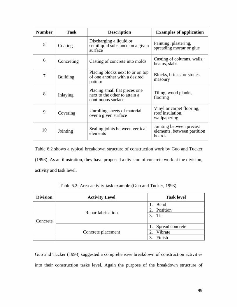
99
Number Task Description Examples of application
5 Coating Discharging a liquid or semiliquid substance on a given surface
Painting, plastering, spreading mortar or glue
6 Concreting Casting of concrete into molds Casting of columns, walls, beams, slabs
7 Building Placing blocks next to or on top of one another with a desired pattern
Blocks, bricks, or stones masonry
8 Inlaying Placing small flat pieces one next to the other to attain a continuous surface
Tiling, wood planks, flooring
9 Covering Unrolling sheets of material over a given surface
Vinyl or carpet flooring, roof insulation, wallpapering
10 Jointing Sealing joints between vertical elements
Jointing between precast elements, between partition boards
Table 6.2 shows a typical breakdown structure of construction work by Guo and Tucker
(1993). As an illustration, they have proposed a division of concrete work at the division,
activity and task level.
Table 6.2: Area-activity-task example (Guo and Tucker, 1993).
Division Activity Level Task level 1. Bend 2. Position Rebar fabrication 3. Tie 1. Spread concrete 2. Vibrate
Concrete
Concrete placement 3. Finish
Guo and Tucker (1993) suggested a comprehensive breakdown of construction activities
into their construction tasks level. Again the purpose of the breakdown structure of
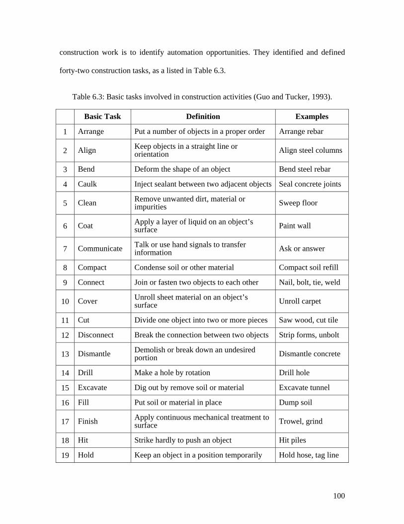
100
construction work is to identify automation opportunities. They identified and defined
forty-two construction tasks, as a listed in Table 6.3.
Table 6.3: Basic tasks involved in construction activities (Guo and Tucker, 1993).
Basic Task Definition Examples
1 Arrange Put a number of objects in a proper order Arrange rebar
2 Align Keep objects in a straight line or orientation Align steel columns
3 Bend Deform the shape of an object Bend steel rebar
4 Caulk Inject sealant between two adjacent objects Seal concrete joints
5 Clean Remove unwanted dirt, material or impurities Sweep floor
6 Coat Apply a layer of liquid on an object’s surface Paint wall
7 Communicate Talk or use hand signals to transfer information Ask or answer
8 Compact Condense soil or other material Compact soil refill
9 Connect Join or fasten two objects to each other Nail, bolt, tie, weld
10 Cover Unroll sheet material on an object’s surface Unroll carpet
11 Cut Divide one object into two or more pieces Saw wood, cut tile
12 Disconnect Break the connection between two objects Strip forms, unbolt
13 Dismantle Demolish or break down an undesired portion Dismantle concrete
14 Drill Make a hole by rotation Drill hole
15 Excavate Dig out by remove soil or material Excavate tunnel
16 Fill Put soil or material in place Dump soil
17 Finish Apply continuous mechanical treatment to surface Trowel, grind
18 Hit Strike hardly to push an object Hit piles
19 Hold Keep an object in a position temporarily Hold hose, tag line
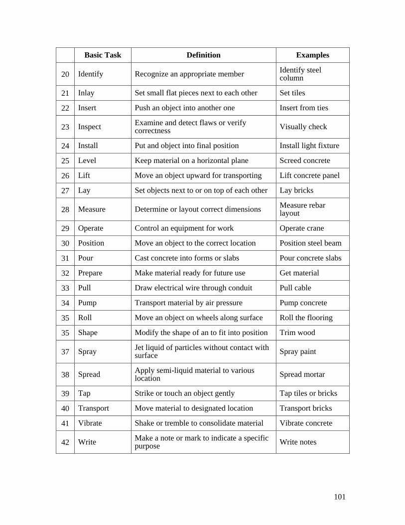
101
Basic Task Definition Examples
20 Identify Recognize an appropriate member Identify steel column
21 Inlay Set small flat pieces next to each other Set tiles
22 Insert Push an object into another one Insert from ties
23 Inspect Examine and detect flaws or verify correctness Visually check
24 Install Put and object into final position Install light fixture
25 Level Keep material on a horizontal plane Screed concrete
26 Lift Move an object upward for transporting Lift concrete panel
27 Lay Set objects next to or on top of each other Lay bricks
28 Measure Determine or layout correct dimensions Measure rebar layout
29 Operate Control an equipment for work Operate crane
30 Position Move an object to the correct location Position steel beam
31 Pour Cast concrete into forms or slabs Pour concrete slabs
32 Prepare Make material ready for future use Get material
33 Pull Draw electrical wire through conduit Pull cable
34 Pump Transport material by air pressure Pump concrete
35 Roll Move an object on wheels along surface Roll the flooring
35 Shape Modify the shape of an to fit into position Trim wood
37 Spray Jet liquid of particles without contact with surface Spray paint
38 Spread Apply semi-liquid material to various location Spread mortar
39 Tap Strike or touch an object gently Tap tiles or bricks
40 Transport Move material to designated location Transport bricks
41 Vibrate Shake or tremble to consolidate material Vibrate concrete
42 Write Make a note or mark to indicate a specific purpose Write notes
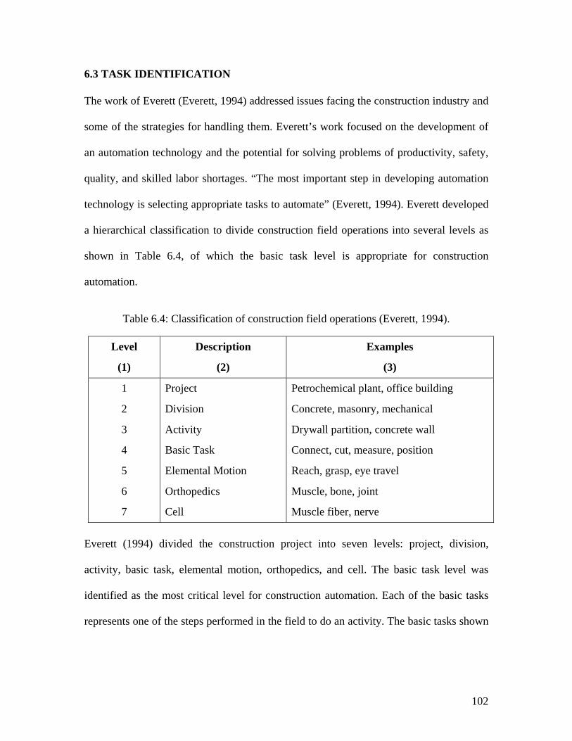
102
6.3 TASK IDENTIFICATION
The work of Everett (Everett, 1994) addressed issues facing the construction industry and
some of the strategies for handling them. Everett’s work focused on the development of
an automation technology and the potential for solving problems of productivity, safety,
quality, and skilled labor shortages. “The most important step in developing automation
technology is selecting appropriate tasks to automate” (Everett, 1994). Everett developed
a hierarchical classification to divide construction field operations into several levels as
shown in Table 6.4, of which the basic task level is appropriate for construction
automation.
Table 6.4: Classification of construction field operations (Everett, 1994).
Level
(1)
Description
(2)
Examples
(3)
1
2
3
4
5
6
7
Project
Division
Activity
Basic Task
Elemental Motion
Orthopedics
Cell
Petrochemical plant, office building
Concrete, masonry, mechanical
Drywall partition, concrete wall
Connect, cut, measure, position
Reach, grasp, eye travel
Muscle, bone, joint
Muscle fiber, nerve
Everett (1994) divided the construction project into seven levels: project, division,
activity, basic task, elemental motion, orthopedics, and cell. The basic task level was
identified as the most critical level for construction automation. Each of the basic tasks
represents one of the steps performed in the field to do an activity. The basic tasks shown
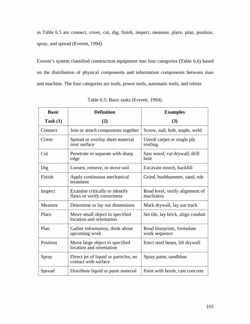
103
in Table 6.5 are connect, cover, cut, dig, finish, inspect, measure, place, plan, position,
spray, and spread (Everett, 1994).
Everett’s system classified construction equipment into four categories (Table 6.6) based
on the distribution of physical components and information components between man
and machine. The four categories are tools, power tools, automatic tools, and robots
Table 6.5: Basic tasks (Everett, 1994).
Basic
Task (1)
Definition
(2)
Examples
(3)
Connect Join or attach components together Screw, nail, bolt, staple, weld
Cover Spread or overlay sheet material over surface
Unroll carpet or single ply roofing
Cut Penetrate or separate with sharp edge
Saw wood, cut drywall, drill hole
Dig Loosen, remove, or move soil Excavate trench, backfill
Finish Apply continuous mechanical treatment
Grind, bushhammer, sand, rub
Inspect Examine critically to identify flaws or verify correctness
Read level, verify alignment of machinery
Measure Determine or lay out dimensions Mark drywall, lay out track
Place Move small object to specified location and orientation
Set tile, lay brick, align conduit
Plan Gather information, think about upcoming work
Read blueprints, formulate work sequence
Position Move large object to specified location and orientation
Erect steel beam, lift drywall
Spray Direct jet of liquid or particles, no contact with surface
Spray paint, sandblast
Spread Distribute liquid or paste material Paint with brush, cast concrete
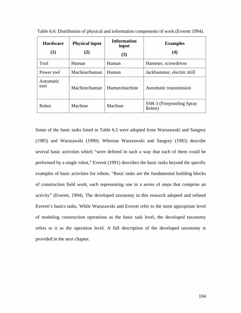
104
Table 6.6: Distribution of physical and information components of work (Everett 1994).
Hardware
(1)
Physical input
(2)
Information input
(3)
Examples
(4)
Tool Human Human Hammer, screwdriver
Power tool Machine/human Human Jackhammer, electric drill
Automatic tool
Machine/human Human/machine Automatic transmission
Robot Machine Machine SSR-3 (Fireproofing Spray Robot)
Some of the basic tasks listed in Table 6.5 were adopted from Warszawski and Sangrey
(1985) and Warszawski (1990). Whereas Warszawski and Sangrey (1985) describe
several basic activities which “were defined in such a way that each of them could be
performed by a single robot,” Everett (1991) describes the basic tasks beyond the specific
examples of basic activities for robots. “Basic tasks are the fundamental building blocks
of construction field work, each representing one in a series of steps that comprise an
activity” (Everett, 1994). The developed taxonomy in this research adopted and refined
Everett’s basics tasks. While Warszawski and Everett refer to the most appropriate level
of modeling construction operations as the basic task level, the developed taxonomy
refers to it as the operation level. A full description of the developed taxonomy is
provided in the next chapter.
105
6.4 ILLUSTRATION OF WORK CLASSIFICATION
To illustrate the structure of work classification, the following scenario is considered for
the activity, install drywall. At the activity level, the activity install and finish a drywall
would normally consists of a sequence of separate construction operations that are
normally performed by one or more crewmembers. Some other activities, such as the
construction of the framing members to which the drywall will be connected, need to be
completed before the starting of activity install drywall. Once the framing crew members
finish their work, another crew starts installing the drywall panels. Finally, another crew
begins finishing the joints. Of course the three activities are related, but the framing task
is a separate operation from installing drywall as well as finishing the joints. As Everett
(1994) described, at the basic task level, the activity, install drywall is broken down into
four basic tasks that one or more crew members would normally perform: (1) measure the
wall and mark the drywall panel; (2) cut the drywall panel to the correct size; (3) move
the panel into position; and (4) connect the panel to its final location (the framing
members).
6.5 MANUFACTURING OPERATIONS
This section reviews how industrial process engineers distinguish between one act and
another in breaking down a task into its constituent processes. Industrial process
engineers are responsible for the tasks and the constituent processes that are performed
on a project. This responsibility consists of process definition, planning, performance,
evaluation, and improvement. In manufacturing, a process may relate to a design process,
a manufacturing process or work process.
106
In manufacturing, there are two types of production operations: processing operations and
assembly operations (Prasad, 1996). Processing operations are those activities that
transform a component from one state of completion to another advance state of
completion, while assembly operations join two or more components together. Processing
operations can usually be classified into one of the following four categories: basic
processes, secondary processes, operations to enhance physical properties, and finishing
operations. Both processing operations and assembly operations require most of the
following inputs: raw material, equipment, tooling and fixtures, energy, and labor.
6.6 INDUSTRIAL PROCESS BREAKDOWN
The industrial process engineer determines the techniques and a time standard in
association with each production task. The objective of determining the work techniques
is to identify the best approach to perform the task. Work techniques involved in
determining the manufacturability of the work components. For example an L-shape
metal component may be machined, or cut to its shape, or welded together from sub-
components. Time standard is used determine how much time the task should take. Each
task is often associated with a component.
One of the issues that is considered during the breakdown of tasks is process planning.
Process planning involves in determining the sequence of each production operation. It
also links the production operations with their associated machines or tools for a
particular component.
107
The main goal of breaking down a task or production operation is to simplify and divide
the job into components and processes. A production operation could be broken down
into its smallest reasonable work components. A reasonable work component is the
practical set of processes into which a task can be divided. In production operations,
drilling a hole is an example of the smallest reasonable work component. Furthermore,
the joining of two components together with a screw and nut is another example of the
smallest reasonable work component in assembly operation.
The breakdown of a task into its constituent processes involves three essential elements:
work breakdown structure (i.e., the layout of the workstations), product breakdown
structure (i.e., the product components), and process breakdown structure (i.e., the
sequence of tasks or processes). The aforementioned elements are interrelated. The
product breakdown structure provides the knowledge about the product, while the process
breakdown structure forms and describes the process, and the work breakdown structure
organizes and defines the works (Prasad, 1996).
A work breakdown structure (WBS) “is a series of interrelated work tasks initially set in
motion by the planning track.” (Prasad, 1996) The WBS describes the structures
associated with organization and management of work tasks. Typically, a WBS contains
three major categories: teams (for example, people, machines, and facilities), tasks (such
as, the work activities, information to about the activities, and any other information to
accomplish an activity), and time schedule.
The product breakdown structure (PtBS) is “the decomposition of a complex system into
a set of hierarchical structure” (Prasad, 1996). The system could be decomposed
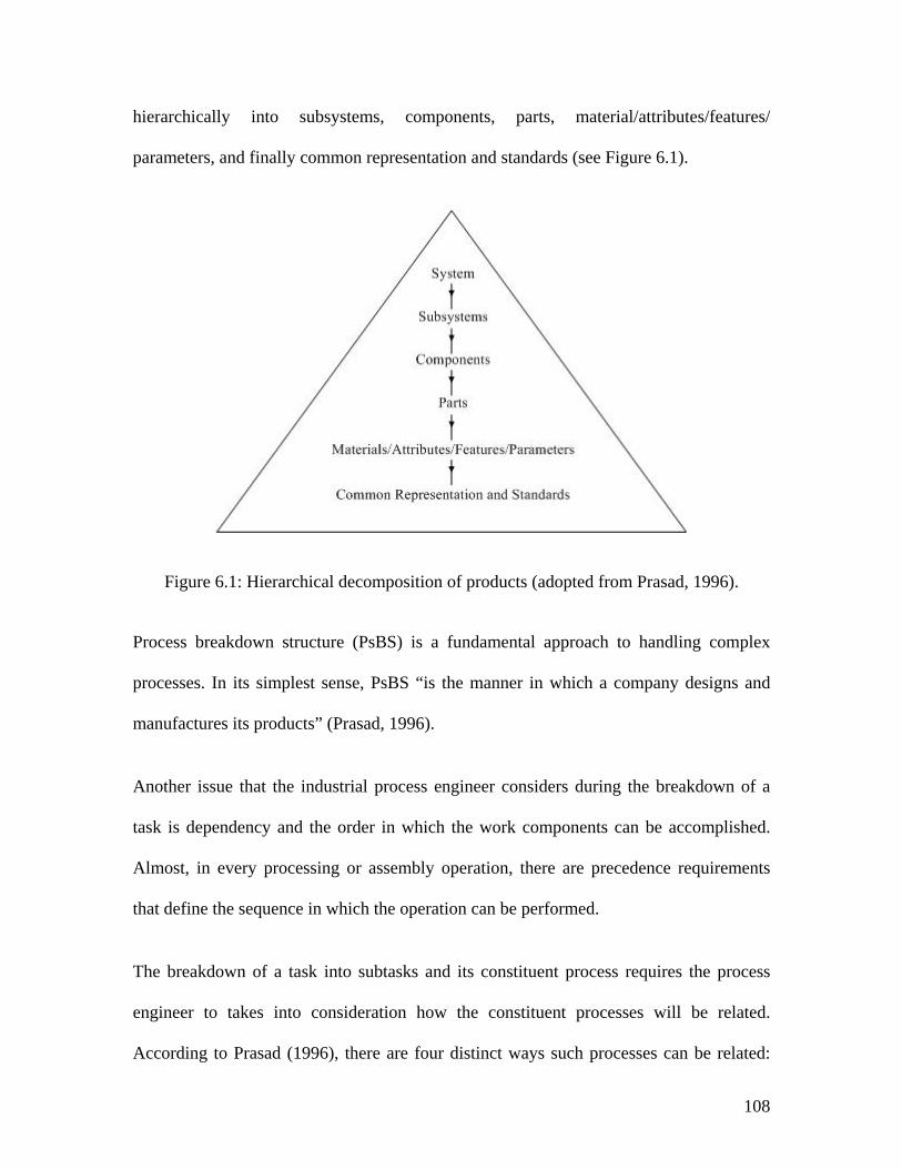
108
hierarchically into subsystems, components, parts, material/attributes/features/
parameters, and finally common representation and standards (see Figure 6.1).
Figure 6.1: Hierarchical decomposition of products (adopted from Prasad, 1996).
Process breakdown structure (PsBS) is a fundamental approach to handling complex
processes. In its simplest sense, PsBS “is the manner in which a company designs and
manufactures its products” (Prasad, 1996).
Another issue that the industrial process engineer considers during the breakdown of a
task is dependency and the order in which the work components can be accomplished.
Almost, in every processing or assembly operation, there are precedence requirements
that define the sequence in which the operation can be performed.
The breakdown of a task into subtasks and its constituent process requires the process
engineer to takes into consideration how the constituent processes will be related.
According to Prasad (1996), there are four distinct ways such processes can be related:
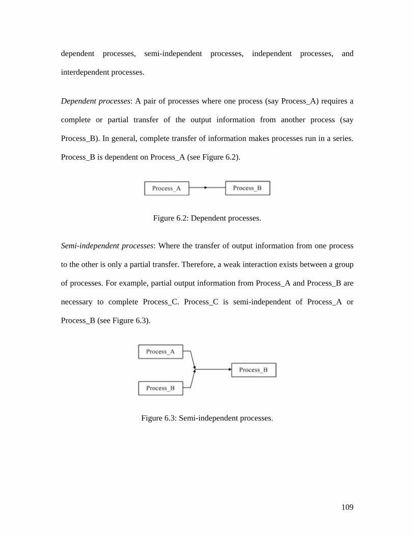
109
dependent processes, semi-independent processes, independent processes, and
interdependent processes.
Dependent processes: A pair of processes where one process (say Process_A) requires a
complete or partial transfer of the output information from another process (say
Process_B). In general, complete transfer of information makes processes run in a series.
Process_B is dependent on Process_A (see Figure 6.2).
Figure 6.2: Dependent processes.
Semi-independent processes: Where the transfer of output information from one process
to the other is only a partial transfer. Therefore, a weak interaction exists between a group
of processes. For example, partial output information from Process_A and Process_B are
necessary to complete Process_C. Process_C is semi-independent of Process_A or
Process_B (see Figure 6.3).
Figure 6.3: Semi-independent processes.
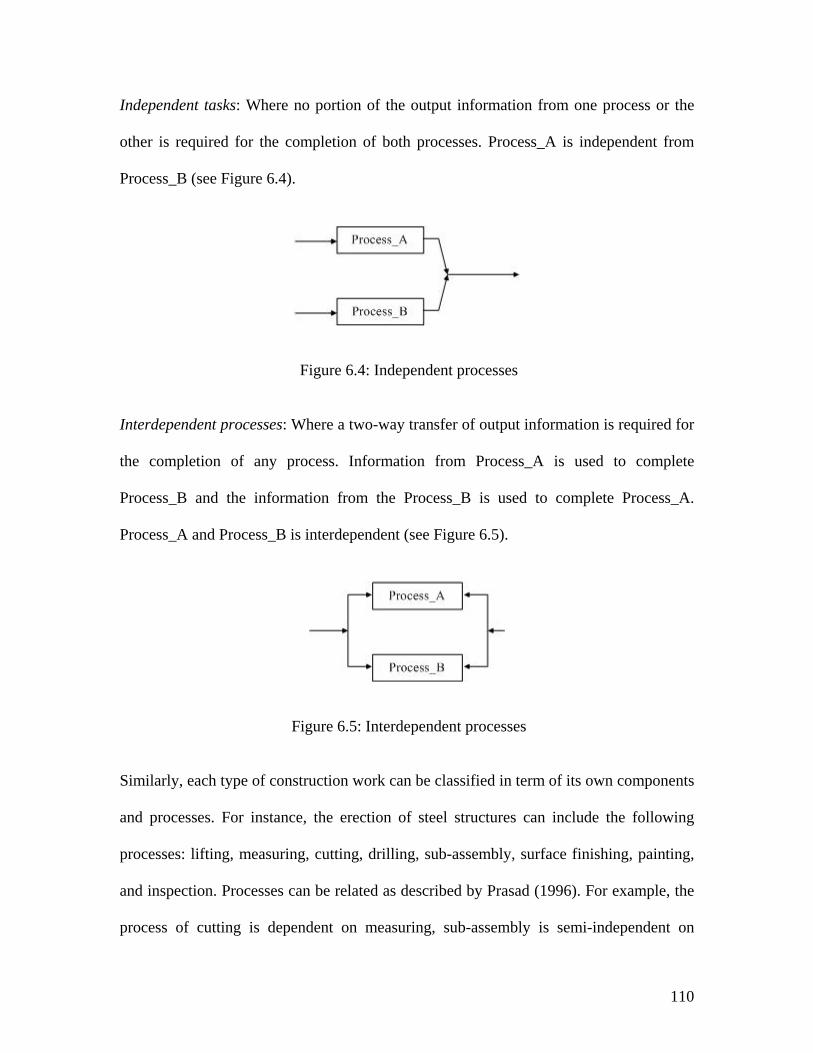
110
Independent tasks: Where no portion of the output information from one process or the
other is required for the completion of both processes. Process_A is independent from
Process_B (see Figure 6.4).
Figure 6.4: Independent processes
Interdependent processes: Where a two-way transfer of output information is required for
the completion of any process. Information from Process_A is used to complete
Process_B and the information from the Process_B is used to complete Process_A.
Process_A and Process_B is interdependent (see Figure 6.5).
Figure 6.5: Interdependent processes
Similarly, each type of construction work can be classified in term of its own components
and processes. For instance, the erection of steel structures can include the following
processes: lifting, measuring, cutting, drilling, sub-assembly, surface finishing, painting,
and inspection. Processes can be related as described by Prasad (1996). For example, the
process of cutting is dependent on measuring, sub-assembly is semi-independent on
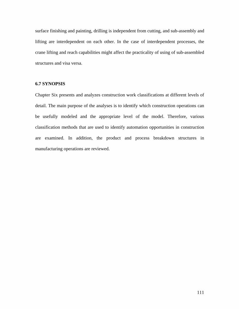
111
surface finishing and painting, drilling is independent from cutting, and sub-assembly and
lifting are interdependent on each other. In the case of interdependent processes, the
crane lifting and reach capabilities might affect the practicality of using of sub-assembled
structures and visa versa.
6.7 SYNOPSIS
Chapter Six presents and analyzes construction work classifications at different levels of
detail. The main purpose of the analyses is to identify which construction operations can
be usefully modeled and the appropriate level of the model. Therefore, various
classification methods that are used to identify automation opportunities in construction
are examined. In addition, the product and process breakdown structures in
manufacturing operations are reviewed.
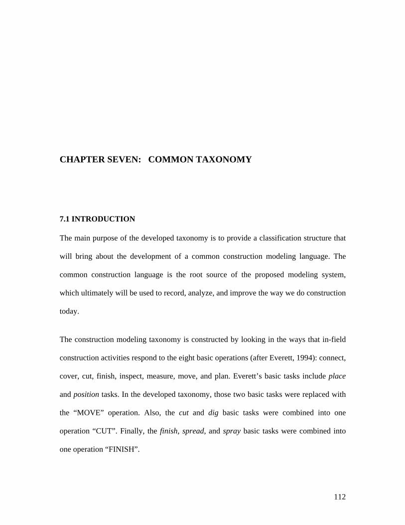
112
CHAPTER SEVEN: COMMON TAXONOMY
7.1 INTRODUCTION
The main purpose of the developed taxonomy is to provide a classification structure that
will bring about the development of a common construction modeling language. The
common construction language is the root source of the proposed modeling system,
which ultimately will be used to record, analyze, and improve the way we do construction
today.
The construction modeling taxonomy is constructed by looking in the ways that in-field
construction activities respond to the eight basic operations (after Everett, 1994): connect,
cover, cut, finish, inspect, measure, move, and plan. Everett’s basic tasks include place
and position tasks. In the developed taxonomy, those two basic tasks were replaced with
the “MOVE” operation. Also, the cut and dig basic tasks were combined into one
operation “CUT”. Finally, the finish, spread, and spray basic tasks were combined into
one operation “FINISH”.
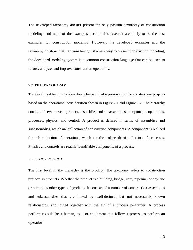
113
The developed taxonomy doesn’t present the only possible taxonomy of construction
modeling, and none of the examples used in this research are likely to be the best
examples for construction modeling. However, the developed examples and the
taxonomy do show that, far from being just a new way to present construction modeling,
the developed modeling system is a common construction language that can be used to
record, analyze, and improve construction operations.
7.2 THE TAXONOMY
The developed taxonomy identifies a hierarchical representation for construction projects
based on the operational consideration shown in Figure 7.1 and Figure 7.2. The hierarchy
consists of seven levels: product, assemblies and subassemblies, components, operations,
processes, physics, and control. A product is defined in terms of assemblies and
subassemblies, which are collection of construction components. A component is realized
through collection of operations, which are the end result of collection of processes.
Physics and controls are readily identifiable components of a process.
7.2.1 THE PRODUCT
The first level in the hierarchy is the product. The taxonomy refers to construction
projects as products. Whether the product is a building, bridge, dam, pipeline, or any one
or numerous other types of products, it consists of a number of construction assemblies
and subassemblies that are linked by well-defined, but not necessarily known
relationships, and joined together with the aid of a process performer. A process
performer could be a human, tool, or equipment that follow a process to perform an
operation.
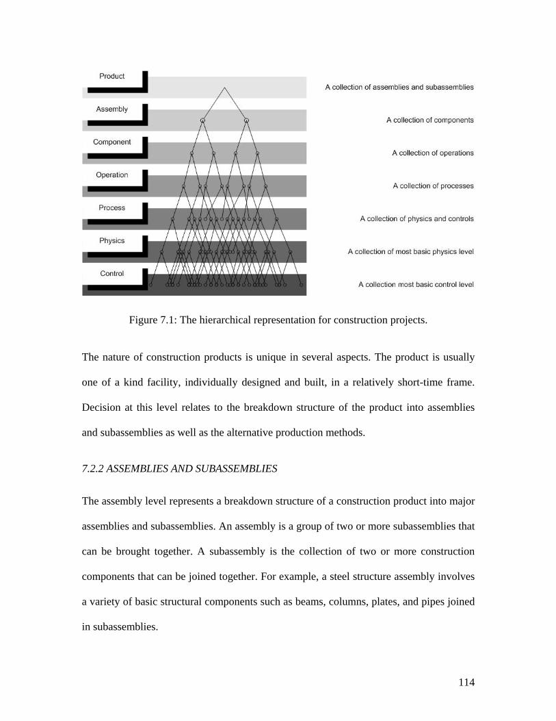
114
Figure 7.1: The hierarchical representation for construction projects.
The nature of construction products is unique in several aspects. The product is usually
one of a kind facility, individually designed and built, in a relatively short-time frame.
Decision at this level relates to the breakdown structure of the product into assemblies
and subassemblies as well as the alternative production methods.
7.2.2 ASSEMBLIES AND SUBASSEMBLIES
The assembly level represents a breakdown structure of a construction product into major
assemblies and subassemblies. An assembly is a group of two or more subassemblies that
can be brought together. A subassembly is the collection of two or more construction
components that can be joined together. For example, a steel structure assembly involves
a variety of basic structural components such as beams, columns, plates, and pipes joined
in subassemblies.
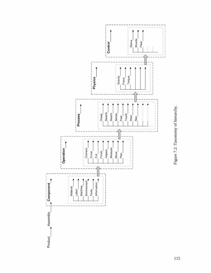
115
Figu
re 7
.2: T
axon
omy
of h
iera
rchy
.
116
7.2.3 COMPONENT
The component level represents the general building materials. It includes the size, shape
and characteristics of materials. Examples of components are brick veneer, studs,
insulation material, etc.
Resources such as, labor, tools, machine and the surrounding environment were added to
this level. Information about material, labor, machine, tools, and the working
environment are included at the component level.
7.2.4 OPERATION
Most construction operations are composed of human individuals, equipment, and
materials. This level is concerned with the technology and details of how operations are
performed and represented. The operation level can be described as the end result of
collection of processes and covers the breakdown structure of most on-site construction
operations. The taxonomy defines a standard operational system that provides a limited
number of reusable construction operations.
The standardized construction operations and their descriptions are shown in Table 7.1.
The “CONNECT” operation is the operation used to connect components or assemblies
together like welding and nailing. “COVER” is the operations for spreading or overlaying
material over the object’s surface e.g. vinyl or carpet flooring. The “CUT” operation is
the operation used to divide or separate one object into two or more pieces. The
“FINISH” operation is the operation used to apply continuous mechanical treatment to a
surface. The “INSPECT” operation is the operation used to examine and detect flaws or
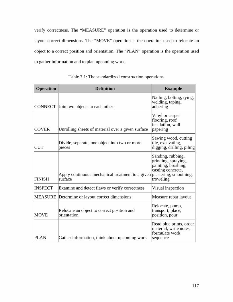
117
verify correctness. The “MEASURE” operation is the operation used to determine or
layout correct dimensions. The “MOVE” operation is the operation used to relocate an
object to a correct position and orientation. The “PLAN” operation is the operation used
to gather information and to plan upcoming work.
Table 7.1: The standardized construction operations.
Operation Definition Example
CONNECT Join two objects to each other
Nailing, bolting, tying, welding, taping, adhering
COVER Unrolling sheets of material over a given surface
Vinyl or carpet flooring, roof insulation, wall papering
CUT Divide, separate, one object into two or more pieces
Sawing wood, cutting tile, excavating, digging, drilling, piling
FINISH Apply continuous mechanical treatment to a given surface
Sanding, rubbing, grinding, spraying, painting, brushing, casting concrete, plastering, smoothing, troweling
INSPECT Examine and detect flaws or verify correctness Visual inspection
MEASURE Determine or layout correct dimensions Measure rebar layout
MOVE Relocate an object to correct position and orientation.
Relocate, pump, transport, place, position, pour
PLAN Gather information, think about upcoming work
Read blue prints, order material, write notes, formulate work sequence
118
7.2.5 PROCESS
The process level consists of a relatively few fundamental work processes, which are
performed over and over again to complete an operation. This level involves micro
modeling and analysis of a set of motions and actions that is executed by human and/or
equipment. Examples of work processes are search, select, grasp, hold, etc.
7.2.6 PHYSICS AND CONTROL
At the physics level humans and equipment are analyzed, with their abilities and
limitations, to determine their capabilities to perform work according to the laws of
physics, mechanics, etc. For humans, this level is concerned with the motions of human
body and the forces that cause those motions. In this sense, it relies upon the second law
of classical Newtonian mechanics.
The control level focuses on both the human control system and the machine automatic
control system. This involves static muscle force control and dynamic muscle velocity
control. It also represents a set of interacting anatomical elements (sensory organs,
nerves, muscles, and bones) that perform physiological functions, which operate
according to biophysical laws (Phillips, 2000).
7.3 THE TAXONOMY OF CONSTRUCTION OPERATION KNOWLEDGE
Figure 7.3 summarizes the main structure of the taxonomy of construction knowledge.
The taxonomy of construction knowledge consists of six major blocks of knowledge
whereas the knowledge of construction operation is the core block. The six major blocks
depend on each other. Thus any value from one block can be shared with almost any
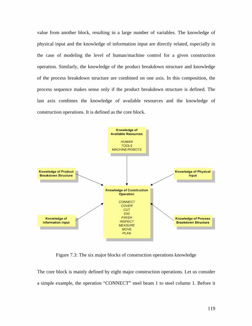
119
value from another block, resulting in a large number of variables. The knowledge of
physical input and the knowledge of information input are directly related, especially in
the case of modeling the level of human/machine control for a given construction
operation. Similarly, the knowledge of the product breakdown structure and knowledge
of the process breakdown structure are combined on one axis. In this composition, the
process sequence makes sense only if the product breakdown structure is defined. The
last axis combines the knowledge of available resources and the knowledge of
construction operations. It is defined as the core block.
Figure 7.3: The six major blocks of construction operations knowledge
The core block is mainly defined by eight major construction operations. Let us consider
a simple example, the operation “CONNECT” steel beam 1 to steel column 1. Before it
120
can be executed, several questions must be initiated and answered. These questions come
from the blocks of construction operation knowledge, such as, “which steel beam and
steel column will be connected to each other?” The answer to this question comes mainly
from the knowledge of product breakdown structure.
The next question is “how to connect the two parts together?” The knowledge of process
breakdown structure provides part of the answer to this question by presenting a sequence
of processes that leads to the realization of the connect operation. Subsequently, it
initiates the following question: “who is going to connect the two parts together?” At this
level, the knowledge of available resources, the interface between human, tools, and
machine is presented and the question is answered accordingly. The designer of the
operation should make the decisions based on best practices or develop his own
combination of human/tool/machine interface to answer the aforementioned question.
The interface between human, tools and machine is based on the level of shared physical
and information input for any given operation.
Additional questions such as “do the physical constraints support this operation?” What
are the physical properties of the steel beam? The answer to these questions comes
directly from the knowledge of physical input and from the physics level as described in
the developed taxonomy.
Furthermore, the main goal of the developed taxonomy is to provide the overall
breakdown structure of construction operations, construction objects, their physical
behavior and information exchange across the defined blocks of construction operations
knowledge.
121
7.4 THE DEVELOPED TAXONOMY VS. THE IFC AND AECXML STANDARDS
The Industry Foundation Classes (IFC’s) and aecXML schemas are two complementary
means for exchanging information within the AEC community (IAI, 2003). The IFC’s
and aecXML are developed by the International Alliance for Interoperability (IAI). The
main goal of the IAI is to facilitate interoperability and exchange information among
project participants throughout the lifecycle of a facility by direct communication
between software applications.
In general, IFC’s are used to model “things”, while aecXML is for talking about things.
AecXML can be used to agree what “door” means, but it won’t describe doors or model
them.
This section reviews both standards and compares them to the developed taxonomy. The
main goal of the comparison is to show the distinct capabilities of the developed
taxonomy to model construction operations.
7.4.1 IFC’S STANDARDS
IFC’s were developed to provide building data models from the computer application
used by one participant to another within the AEC domain; with no loss of information.
IFC’s are defined by IAI as data elements that represents the parts in a constructed
facility, or elements of the processes, and contain the relevant information about those
parts. IFC’s can be used electronically to produce an electronic project model of the
constructed facility that contains all the information of the parts and their relationships to
be shared among project participants. The project model constitutes an object-oriented
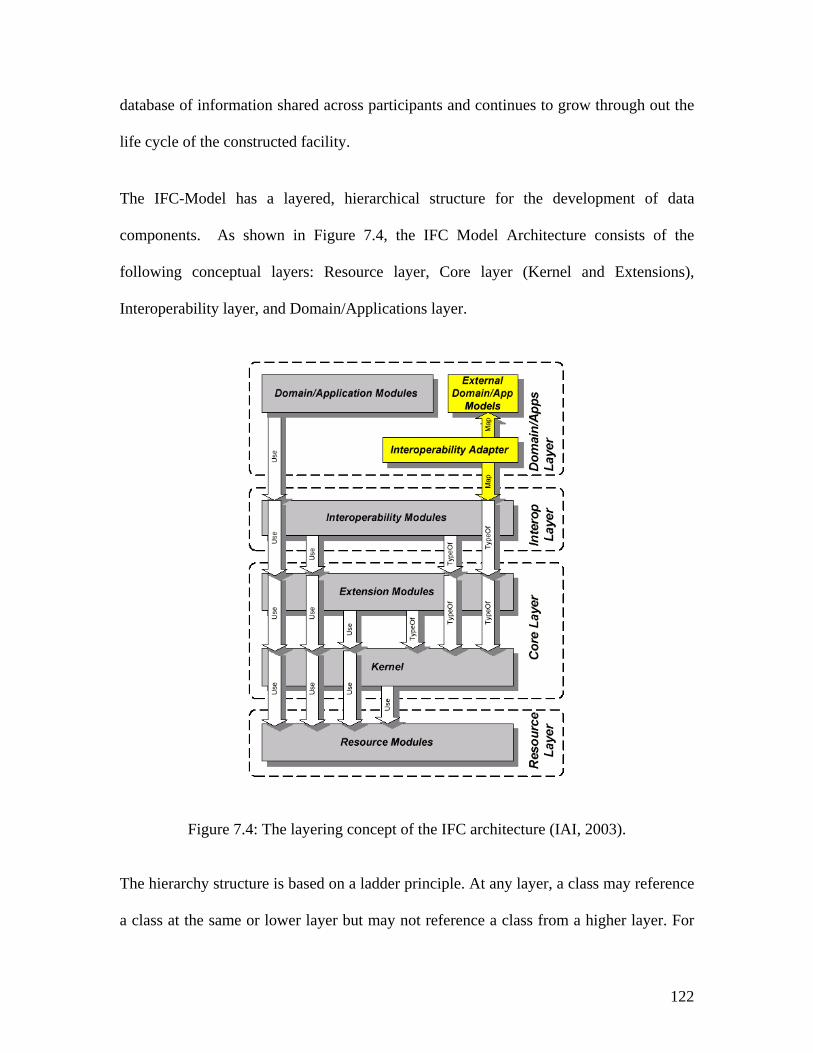
122
database of information shared across participants and continues to grow through out the
life cycle of the constructed facility.
The IFC-Model has a layered, hierarchical structure for the development of data
components. As shown in Figure 7.4, the IFC Model Architecture consists of the
following conceptual layers: Resource layer, Core layer (Kernel and Extensions),
Interoperability layer, and Domain/Applications layer.
Figure 7.4: The layering concept of the IFC architecture (IAI, 2003).
The hierarchy structure is based on a ladder principle. At any layer, a class may reference
a class at the same or lower layer but may not reference a class from a higher layer. For
123
example, Resource classes may only reference or use other Resource classes. Resource
classes may not reference classes from the Core layer.
The Resource layer (shown at the bottom of Figure 7.4) provides resource classes used
by classes in the higher levels, such as the core layer. Within the Resource layer the
following schemes are included (IAI, 2003):
IfcActorResource: This scheme defines the properties of persons and organizations whose
services may be used within a project.
IfcClassificationResource: This scheme defines the assignment of classifications to
objects.
IfcCostResource: This scheme provides the means to identify the cost of an object or
aggregation of objects.
IfcDateAndTimeResource: This scheme defines dates and times that may be applied.
IfcDocumentResource: This scheme defines object types related to the documents and
document management.
IfcGeometryResource: This scheme specifies the resources for the geometric and
topological representation of the shape or a product.
IfcMaterialResource: This scheme contains the types and classes which are used to define
and manipulate materials and their properties.
124
IfcMeasureResource: This scheme specifies units and measures that may be assigned to
quantities.
IfcPropertyResource: This scheme defines a set of basic property objects that can be
associated with IFC objects through the IfcPropertySet.
IfcRepresentationResource: This scheme defines the representation of shape and
topology as important definitional properties for products defined within the IFC object
model.
IfcUtilityResource: This scheme deals with general concepts such as identification,
ownership, history, and tables.
The Core layer provides a Core project model that contains the Kernel and several Core
Extensions. Within the Core layer the following schemes are included:
IfcKernel: This scheme defines the most abstract part of the IFC architecture. It handles
the basic functionality, relative location of products in space, sequence of processes in
time, or general-purpose grouping and nesting mechanism.
IfcControlExtension: This scheme defines basic concepts for capturing controls related to
any object in the IFC model derived from IfcObject.
IfcModelingAidExtension: This scheme defines basic object concepts used as aids in the
development of the project model, particularly those related to geometric placement and
alignment.
125
IfcProcessExtension: This scheme captures information concerning the work and
construction resources uses in the process required in order to create a product.
IfcProductExtension: This scheme defines basic objects concepts such as Building, Site,
and Space.
IfcProjectMgmtExtension: This scheme defines basic concepts used in the project
management processes.
The Interoperability layer provides a set of modules defining concepts or objects
common across the AEC industry domains. Within the Interoperability layer the
following schemes are included:
IfcSharedBldgElements: This scheme covers the definition of building elements that are
shared among several IFC domain or application type models.
IfcSharedBldgServiceElements: This scheme includes concepts such as equipment,
fixture, and electrical appliance.
IfcSharedSpatialElements: This scheme covers the definition of spatial elements that are
shared among several IFC domain or application type models.
The Domain/Applications layer provides a set of modules tailored for specific AEC
industry domains. Within the Domain/Applications layer the following schemes and
classes are included:
126
IfcArchitectureDomain: This scheme defines basic objects concepts used in the
Architectural CAD applications that have not been generalized.
IfcConstructionMgmtDomain: This scheme contains defined types and classes that
capture concepts and data requirements for construction management processes.
IfcFacilitiesMgmtDomain: This scheme defines basic concepts in the facilities
management domain.
IfcHVACDomain: This scheme defines basic object concepts required for interoperability
between Building Service domain extensions and other domain extensions.
7.4.2 AECXML STANDARDS
aecXML is a new schema to establish a common data format to transfer specific
information over the Internet free from human intervention. This information may be
resources such as projects, documents, materials, parts, organizations, or activities such
as proposals, design, estimating, scheduling, and construction (aecXML, 2003). aecXML
was initially developed and introduced to the construction industries by Bentley Systems.
The name “aecXML” derives from AEC and XML “eXtensible Markup Language”.
XML, a term for a type of structured text data, is derived from the earlier SGML
“Structured Generalised Markup Language”, which in turn derived from its well known
sub-set HTML “HyperText Markup Language”.
aecXML is textual representation of data. The basic components in aecXML is the
element, that is, a piece of text bounded by matching tags such as <BeginDate> and
127
</BeginDate>. Elements may contain other elements, “raw” text, or a mixture of the two.
Consider the following example:
<Person>
<Name> Sami </Name>
<PhoneNumber> (919) 111-1111 </PhoneNumber>
</Person>
The Name element is delimited by the start-tag <Name> and the end-tag </Name>, and it
contains only character data. The text between the start-tag and the corresponding end-
tag, including the embedded tags, is called an element, and the structures between the
tags are referred to as the content. The term subelement is also used to describe the
relation between and element and it is component elements. Thus <Name>…</Name> is
a subelement of <Person>…</person> in the example above.
Examples of aecXML elements are <BuildingComponent>, <Document>,
<ConstructionData>, <Assembly>, <AssemblyCost> etc. The aecXML elements can be
used across multiple disciplines. There are no predefined tags in aecXML; new tags may
be defined at will.
7.4.3 THE COMPARISON
The developed taxonomy is conceptually related to the development concepts of the
Industry Foundation Classes (IFC’s) and aecXML standards. However, because of their
distinct target scope, the focus and detail of the two systems are different. The purpose of
the IFC and aecXML standards is to enable data exchange, sharing, and interoperability
within architecture, engineering, and construction (AEC) applications throughout the
128
project lifecycle. As they are currently proposed, The IFC standards are designed to
represent all graphic data involved in the AEC industries, while the aecXML system is
designed for all non-graphic data.
The IFCs have a rich library of objects designed for recording Architecture, Engineering
and Construction (AEC) information data. On the other hand, the IFCs don’t provide the
data structure that is needed for modeling construction operations. For example, the IFCs
don’t have clear criteria that describe the decomposition of objects into its basic
components. Consider the following example; the IfcBuildingElement includes all
elements that are primarily part of the construction of a building, such as walls, beams,
etc. The wall is modeled in the IfcWall class, a subclass of IfcBuildingElement, however,
there is no clear guidance on how to decompose the wall into its elements and record the
decomposition information in the IFCs.
The developed taxonomy provides a clear guidance on how to decompose construction
activities into their basic elements. The taxonomy provides three primary hierarchal
levels that describe decomposition of any facility: product, assemblies and subassemblies,
and components. For instance, a brick wall can be modeled as a subassembly and the
bricks that make up the wall can be modeled at components level. Each component can
have its own geometrical and physical representation based on its type.
Furthermore, the extent of the IFCs scope is much bigger and more complex than what is
needed for the modeling construction operations alone. Other classification in addition to
the IFCs needs to be developed to achieve the goal of modeling construction operations
as described in the developed taxonomy. Thus, the taxonomy becomes remarkably
129
important because it focuses on the classification structure of construction work at several
levels of details, so that construction operations can be usefully modeled. On other hand,
the IFCs doesn’t breakdown the construction work into well defined operations (i.e.
move, cut, etc.), but it provides the rich library of classes where the information can be
defined and recorded.
To demonstrate how the taxonomy intersects or overlaps with the IFCs, we chose to
partially map the proposed taxonomy to the IFC standards. The mapping process shows
how the two systems intersect and point out the potential use of the taxonomy to enhance
the current IFCs in order to adequately support modeling of construction operations. For
example, there are two major classes in the IFC’s that support the modeling of
construction operations and processes, as they are presented in the developed taxonomy:
IfcProcess and IfcWorkTask. Both classes are defined at the core layer. The IfcProcess
class represents any general actions taking place in completing any architecture,
engineering, or construction work. On the other hand, the IfcWorkTask class, a subtype of
IfcProcess, can be used to represent processes that make up a construction operation. The
IfcWorkTask class includes information such as work plans, work methods, and
scheduling data. Again the IFCs only provide the class where work tasks can be defined,
but the classes don’t provide explicit guidance regarding the classification of construction
operations, for example “CUT”.
The IfcProcess class can be mapped to the operation level in developed taxonomy just as
the IfcWorkTask class can be mapped to the process level. IfcWorkTask can represent a
process at any level of detail, from the overall project level to very detailed tasks. For
130
example, the project development phase, systems design, construction activities, and
construction operations can all be represented as instances of IfcWorkTask. In addition,
the IfcRelNestsProcesses class can be used to represent the relationships between a work
task and its subtasks.
The IfcRelProcessOperatesOn class can be used to establish a relationship between
processes (IfcProcess) and the products (IfcObject) upon which they operate.
Construction operations such as, MOVE, CONNECT, etc. can be defined in this class.
Also, the IfcResource class can be used to represent the role that certain ‘thing’ plays on a
construction project. The IFCs currently supports five different resources types:
subcontractor, construction equipment, and construction material, crew, and product
resources. A product resource is used in the case where a product that results from a work
task is used as a resource in another process. The IfcResouce class can be mapped to the
component level in the taxonomy.
The IfcResource class doesn’t represent the ‘thing’ it self. Therefore, in situations where
further information is needed about the ‘thing’ that is being modeled as a resource, the
IfcResource class can be associated with other instances that represent those things, such
as IfcMaterialRes. This is a key element to the development of the physically-based
modeling approach where information about the physical properties of resources is
needed to determine their physical behaviors.
The mapping approach of the developed taxonomy to the IFCs clearly shows the areas
where the two systems overlap. As described above, at the conceptual level, both systems
131
agree on the definition of things such as construction process, construction operations,
and construction resources. However, the taxonomy provides a more explicit guidance on
how to decompose a product into its basic elements, and on how to classify construction
work into standard set of operations employing a common construction language.
Because of the focuses on inter-process interoperability, the IFC may not address as
much specific detail information of various construction operations functionality as is
needed to adequately support modeling of those operations. Therefore, the taxonomy can
be looked upon as complementary efforts to extend the IFC objects in areas where the
IFCs themselves are insufficient to support modeling of construction operations.
Nonetheless, the taxonomy has the potential to provide a prototype that may eventually
be adopted as an IFC extension that supports the modeling of construction operations.
On the other hand, the aecXML is a standardized means of communicating information in
a business transaction, not a repository for holding it. aecXML can be used to agree on
what certain ‘things’ mean, such as door or window, however aecXML won’t model the
thing. It complements the IFCs by providing a set of keywords and named data attributes,
so that all users will employ the same naming logic and grouping, and software will be
able to make use of the data without being interpreted by humans.
7.5 A SCALABLE CONCURRENT TAXONOMY: INTEGRATED PRODUCT AND PROCESS DEVELOPMENT
In order to address the issue of scalability, micro-modeling, and macro-modeling during
the various design and construction phases, a concurrent structure that describes the
132
design and construction phases based on their potential level(s) of interface with the
proposed taxonometric structure is needed.
Typically, products that are produced by the AEC industry go through several distinct
phases in their life span. Traditionally, those phases are carried out in a linear fashion that
makes it difficult to integrate the modeling system at the early stages of the design
process. Therefore a different design approach that focuses on the realization of the
product is needed. Unlike traditional design approaches, the developed concurrent
structure describes the following design and construction phases: feasibility study,
conceptual design, preliminary design, detailed design, construction planning,
construction operations, and operation and support. The developed concurrent structure
creates a hierarchical level of interactivity between the various design and construction
phases. Also, it makes the integration between the various design phases and the
taxonometric structure more feasible.
The concurrent structure distinguishes two categories of design and construction phases:
product-oriented phases and process-oriented phases. The product-oriented category
includes the feasibility study, conceptual design, and preliminary design. Where the
process-oriented category includes the construction planning, construction operations,
and operation and support phases. The detailed design phase falls under both categories
and bridge the gap between the product-oriented phases and the process-oriented phases.
Similarly, the concurrent structure implements the same classification methodology that
described in the taxonometric structure. The product, assembly, and component levels of
133
the hierarchal taxonomy are categorized as product-oriented levels. While the operation,
process, physics and controls levels are classified as process-oriented levels.
The product-oriented and process-oriented categories create a common ground between
the design and construction phases and the taxonometric structure. The next step is to
establish the interfaces between each of the design phases and various levels within the
taxonometric structure. As shown in Figure 7.5, the design phases and the taxonometric
levels from the product-oriented category are linked together. For instance the
preliminary design phase is linked to the assembly and component levels. In the same
way, the interface between the phases and levels in the process-oriented category were
established.
The established links between the design phases and the taxonometric levels defines the
complexity and the level of detail for the construction models that interfaces with the
product or process design phases. The taxonometric structure supports this philosophy
because it is structured to model construction operations at various levels of detail
including the macro-level and the micro-level.
For example, at the operation level during the process design of a wall construction, the
construction process designer, for constructability reasons, determined to use drywall on
steel studs rather than masonry construction, as defined by the product designer. The
information generated from the operation level offers recommendation regarding the
desired wall components including materials and tools. The wall components are defined
at the component level. Therefore, information collected from the component and
134
assembly level may have significant input into the product design at the preliminary
design phase.
Macro-Modeling refers to higher level decision making, while micro-modeling refers to
the detailed level of decision making. For instance, the process level can be classified as a
micro-modeling level when compared to the operation level. The process level returns all
the processes needed to complete a construction operation. The same concept exists in the
design and construction phases as well. The detailed designed phase is considered a
micro-design phase when compared to the preliminary design phase; however, it is
considered a macro design phase when compared to the construction planning phase.
To illustrate how the proposed taxonometric structure can be usefully utilized at various
design phases let us consider a steel structure example. At the conceptual design phase,
product designers are only interested in the overall project and its major assemblies. It is
considered a tedious practice to present the designer with detail from construction
operation and process levels to consider during the conceptual design phase. Thus, a
higher-level model (macro-model) can be presented to the product designer from the
assembly level to show the configuration of the steel structure assembly. Afterward,
during the preliminary design phase the designer can be presented with more detailed
models, which includes models from the assembly and components levels.
In summary, the proposed concurrent structure, shown in Figure 7.5, forms the basis
where the issue of scalability can be implemented. Also a new classification was
developed to usefully facilitate the use of taxonometric structure during the various
design stages.
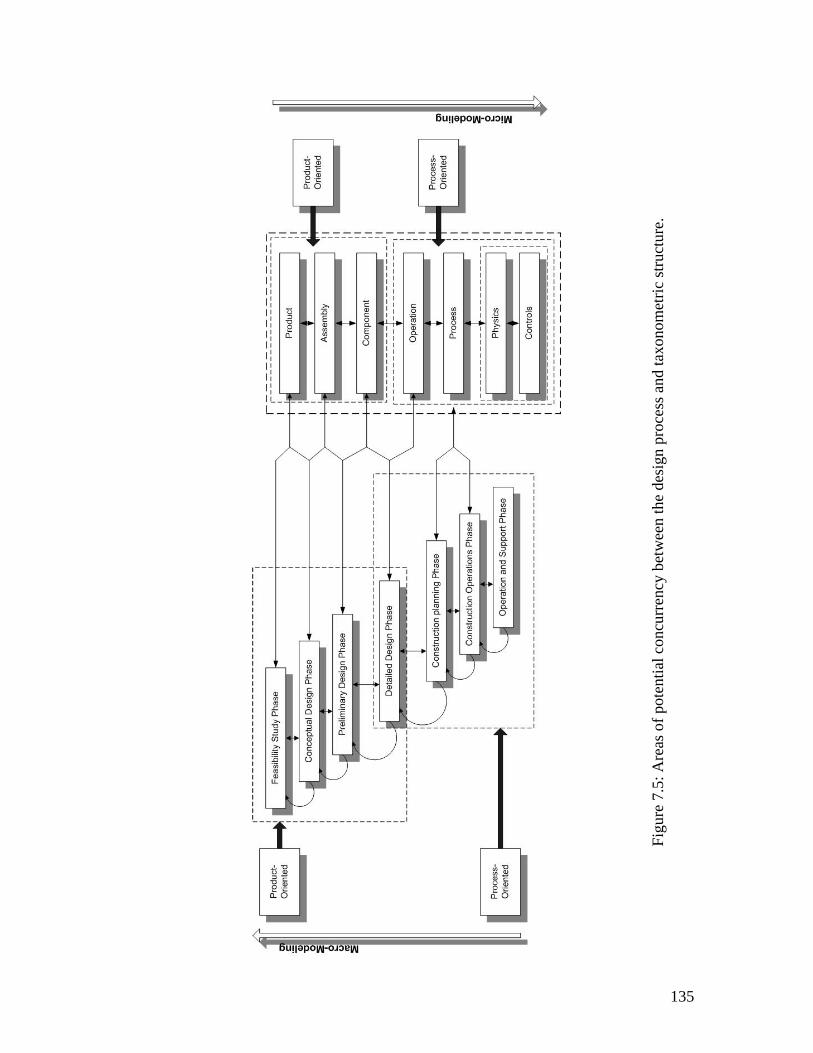
135
Figu
re 7
.5: A
reas
of p
oten
tial c
oncu
rren
cy b
etw
een
the
desi
gn p
roce
ss a
nd ta
xono
met
ric st
ruct
ure.
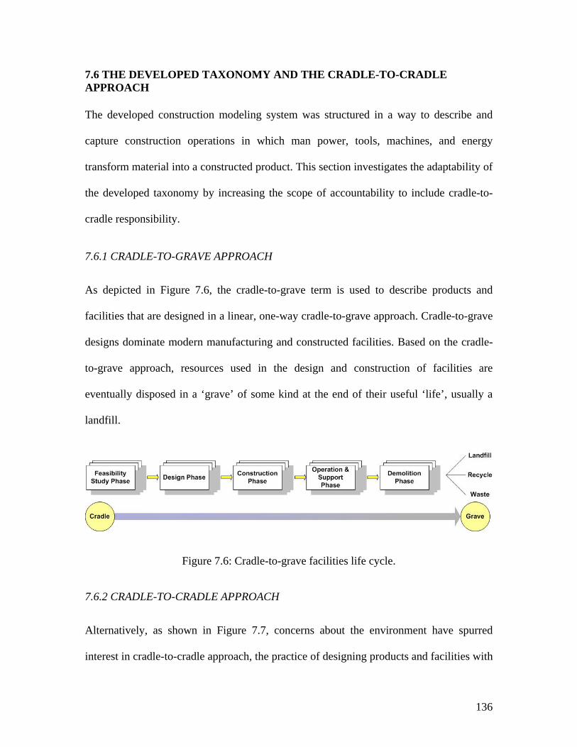
136
7.6 THE DEVELOPED TAXONOMY AND THE CRADLE-TO-CRADLE APPROACH
The developed construction modeling system was structured in a way to describe and
capture construction operations in which man power, tools, machines, and energy
transform material into a constructed product. This section investigates the adaptability of
the developed taxonomy by increasing the scope of accountability to include cradle-to-
cradle responsibility.
7.6.1 CRADLE-TO-GRAVE APPROACH
As depicted in Figure 7.6, the cradle-to-grave term is used to describe products and
facilities that are designed in a linear, one-way cradle-to-grave approach. Cradle-to-grave
designs dominate modern manufacturing and constructed facilities. Based on the cradle-
to-grave approach, resources used in the design and construction of facilities are
eventually disposed in a ‘grave’ of some kind at the end of their useful ‘life’, usually a
landfill.
Figure 7.6: Cradle-to-grave facilities life cycle.
7.6.2 CRADLE-TO-CRADLE APPROACH
Alternatively, as shown in Figure 7.7, concerns about the environment have spurred
interest in cradle-to-cradle approach, the practice of designing products and facilities with
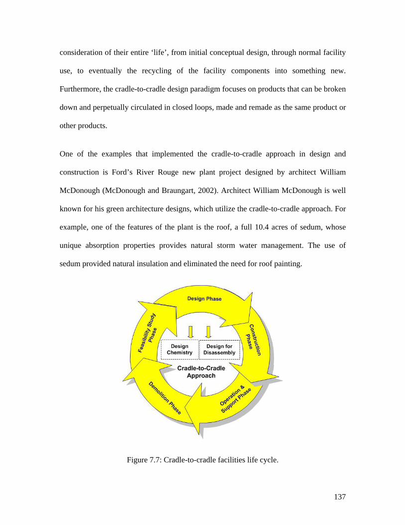
137
consideration of their entire ‘life’, from initial conceptual design, through normal facility
use, to eventually the recycling of the facility components into something new.
Furthermore, the cradle-to-cradle design paradigm focuses on products that can be broken
down and perpetually circulated in closed loops, made and remade as the same product or
other products.
One of the examples that implemented the cradle-to-cradle approach in design and
construction is Ford’s River Rouge new plant project designed by architect William
McDonough (McDonough and Braungart, 2002). Architect William McDonough is well
known for his green architecture designs, which utilize the cradle-to-cradle approach. For
example, one of the features of the plant is the roof, a full 10.4 acres of sedum, whose
unique absorption properties provides natural storm water management. The use of
sedum provided natural insulation and eliminated the need for roof painting.
Figure 7.7: Cradle-to-cradle facilities life cycle.
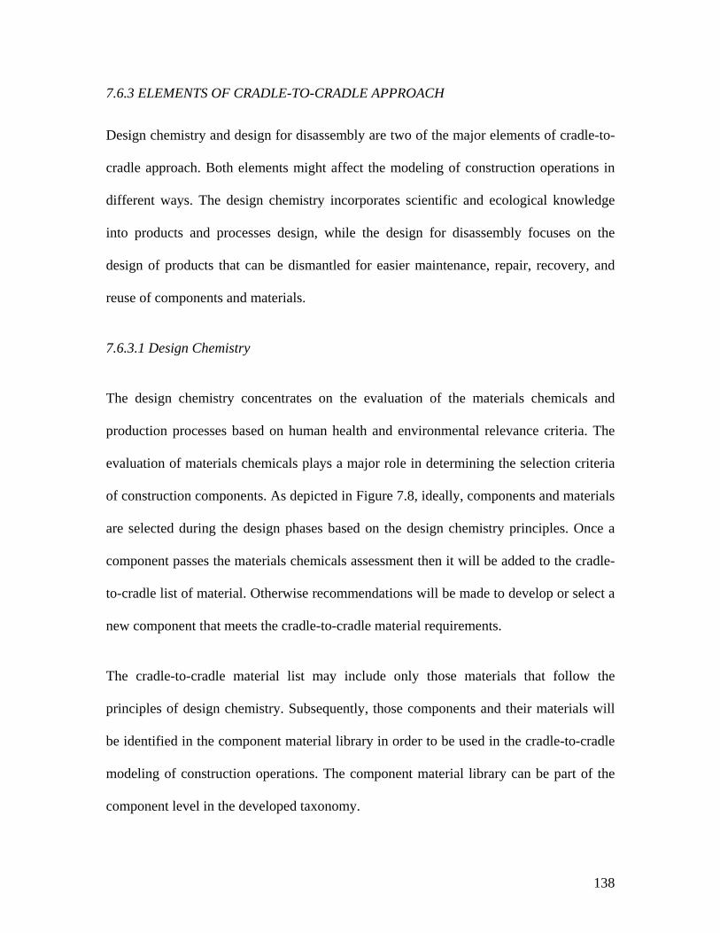
138
7.6.3 ELEMENTS OF CRADLE-TO-CRADLE APPROACH
Design chemistry and design for disassembly are two of the major elements of cradle-to-
cradle approach. Both elements might affect the modeling of construction operations in
different ways. The design chemistry incorporates scientific and ecological knowledge
into products and processes design, while the design for disassembly focuses on the
design of products that can be dismantled for easier maintenance, repair, recovery, and
reuse of components and materials.
7.6.3.1 Design Chemistry
The design chemistry concentrates on the evaluation of the materials chemicals and
production processes based on human health and environmental relevance criteria. The
evaluation of materials chemicals plays a major role in determining the selection criteria
of construction components. As depicted in Figure 7.8, ideally, components and materials
are selected during the design phases based on the design chemistry principles. Once a
component passes the materials chemicals assessment then it will be added to the cradle-
to-cradle list of material. Otherwise recommendations will be made to develop or select a
new component that meets the cradle-to-cradle material requirements.
The cradle-to-cradle material list may include only those materials that follow the
principles of design chemistry. Subsequently, those components and their materials will
be identified in the component material library in order to be used in the cradle-to-cradle
modeling of construction operations. The component material library can be part of the
component level in the developed taxonomy.
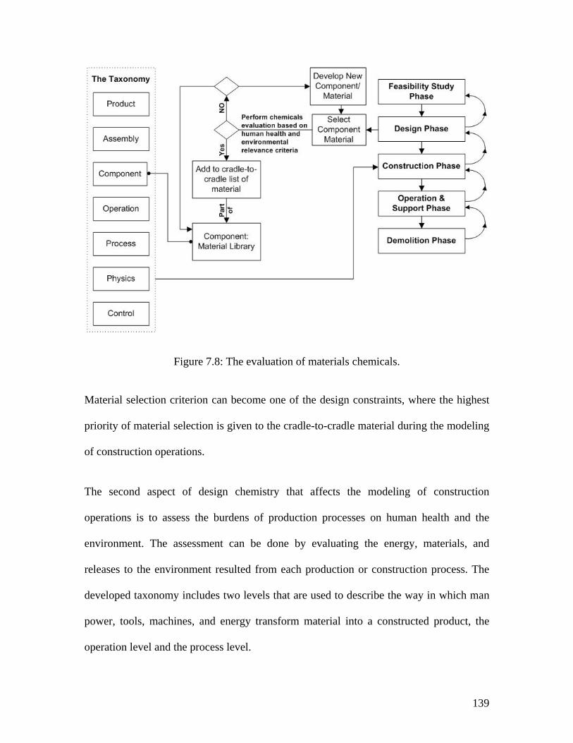
139
Figure 7.8: The evaluation of materials chemicals.
Material selection criterion can become one of the design constraints, where the highest
priority of material selection is given to the cradle-to-cradle material during the modeling
of construction operations.
The second aspect of design chemistry that affects the modeling of construction
operations is to assess the burdens of production processes on human health and the
environment. The assessment can be done by evaluating the energy, materials, and
releases to the environment resulted from each production or construction process. The
developed taxonomy includes two levels that are used to describe the way in which man
power, tools, machines, and energy transform material into a constructed product, the
operation level and the process level.
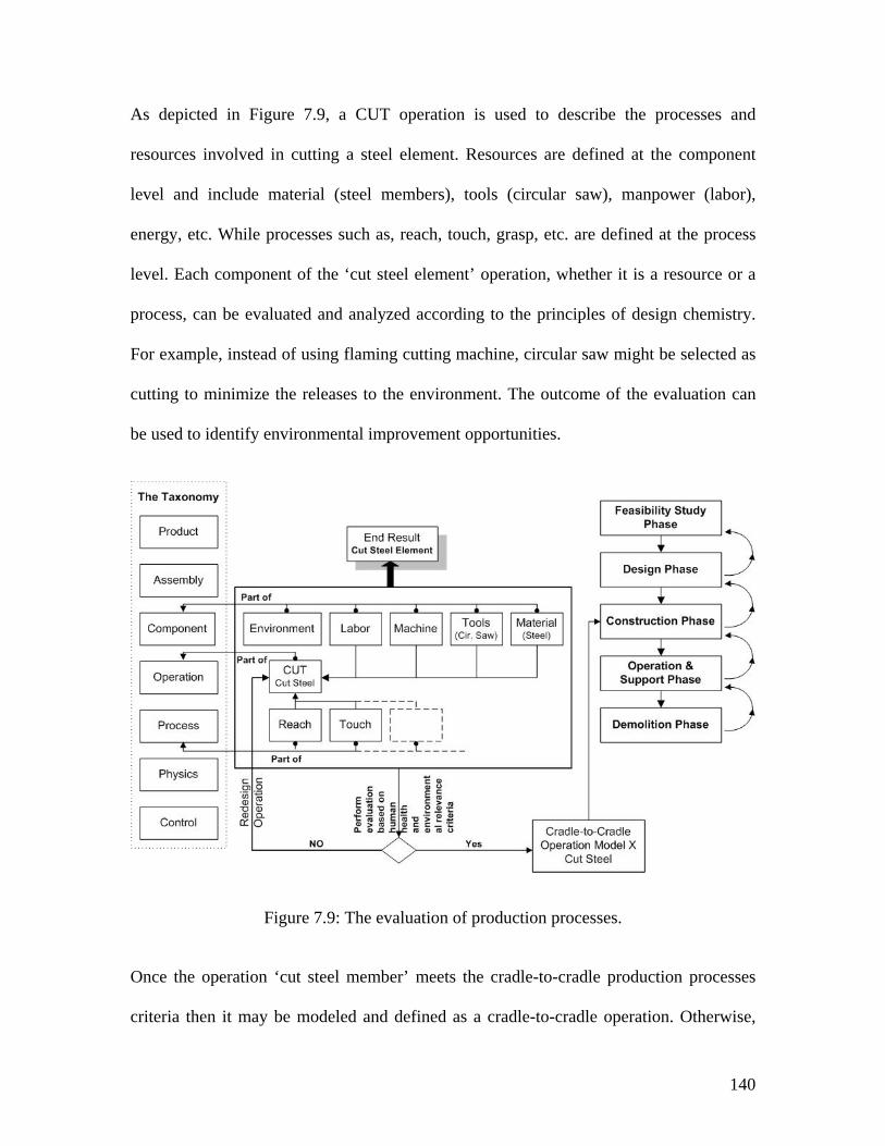
140
As depicted in Figure 7.9, a CUT operation is used to describe the processes and
resources involved in cutting a steel element. Resources are defined at the component
level and include material (steel members), tools (circular saw), manpower (labor),
energy, etc. While processes such as, reach, touch, grasp, etc. are defined at the process
level. Each component of the ‘cut steel element’ operation, whether it is a resource or a
process, can be evaluated and analyzed according to the principles of design chemistry.
For example, instead of using flaming cutting machine, circular saw might be selected as
cutting to minimize the releases to the environment. The outcome of the evaluation can
be used to identify environmental improvement opportunities.
Figure 7.9: The evaluation of production processes.
Once the operation ‘cut steel member’ meets the cradle-to-cradle production processes
criteria then it may be modeled and defined as a cradle-to-cradle operation. Otherwise,
141
the ‘cut steel member’ operation will go through several redesign cycles until satisfactory
results are achieved.
7.6.3.2 Design for disassembly
Another aspect related to the cradle-to-cradle approach is the disassemblability of
constructed facilities. According to cradle-to-cradle approach, after a facility has
completed its useful life, it must be disassembled then, reused or recycled.
Facilities that are designed for disassembly can be quickly and easily broken down so that
the components can be repaired, reused, or recycled. Therefore, designer and builders
should evaluate the ease of disassembly operations during the early design stages. The
evaluation can be performed in two ways: one by studying the design drawing and the
technical specifications or by building a prototype to study the disassembly operations.
Prototypes can either be physical or virtual. Physical prototypes are expensive and time
consuming to build and modify, while virtual prototypes often can be generated and
modified quickly to test new concepts. Thus, disassemblability can be evaluated by
performing disassembly operations on virtual prototypes utilizing the developed
construction modeling system.
In order to evaluate disassemblability, a disassembly process model is needed. The
disassembly process model describes information regarding disassembly operations
sequence, component removal sequence, and tools information etc. Information needs to
be structured and stored in a useful way to allow later evaluation of disassemblability;
simulation of the disassembly processes; and optimization of the disassembly processes.
142
Useful information related to the disassembly processes can be captured by the developed
modeling system at several levels of detail. Figure 7.10 shows the disassembly sequence
of components, operations, processes, and the components needed to complete the
disassembly of column 6A.
Three construction operations are needed: PLAN, CUT, and MOVE. PLAN the
disassembly work for column 6A, then CUT (unfasten) nuts 6A-1, 6A-2, 6A-3, and 6A-4,
and finally MOVE the column with the aid of mobile crane. These operations are defined
and captured at the operation level. The detailed processes (e.g., grasp and unfasten) of
the CUT operation are captured at the process level. The component and resources are
captured at the component level (e.g., a mobile crane or steel column 6A).
In summary, the developed taxonomy and its modeling system can be expanded to
increase the scope of accountability to include cradle-to-cradle responsibility. Modeling
the disassembly processes of products is a subject with considerable potential for a future
research that expands on the developed taxonomy.
7.7 SYNOPSIS
In Chapter Seven, a common taxonomy for modeling construction operations is
developed. First, the taxonometric hierarchy consists of seven levels of classification:
product, assemblies and subassemblies, components, operations, processes, physics, and
control.
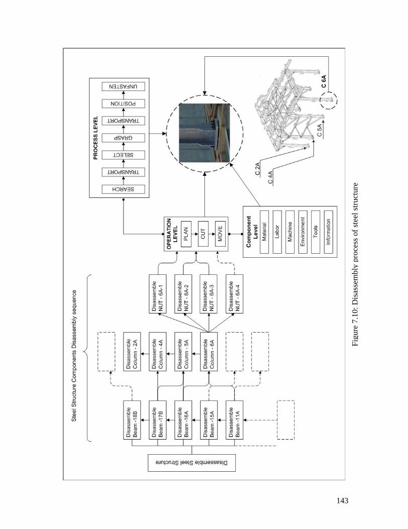
143
Figu
re 7
.10:
Dis
asse
mbl
y pr
oces
s of s
teel
stru
ctur
e
144
The seven hierarchical levels are established by examining the ways that construction
field operations are being carried out. Second, six major blocks of construction
knowledge are identified and information about the interaction processes that is required
to model construction operations in a logical way are described. Third, schemes for
modeling information in the construction domain such as aecXML and IFC’s are
presented. Then the developed taxonomy is partially mapped to the IFC standards to
identify where both systems intersect or overlap and their advantages and limitations.
Fourth, areas of potential concurrency between the design process and the developed
taxonometric structure are presented.
Also, a new concurrent classification structure is developed to usefully facilitate the use
of such a structure during the various stages of design. The new concurrent classification
structure distinguishes between two categories of design and construction phases:
product-oriented phases and process-oriented phases. Finally, this chapter investigates the
adaptability of the developed modeling system by increasing the scope of accountability
to include cradle-to-cradle responsibility. Design chemistry and design for disassembly
are discussed and an example for the disassembly of a steel structure is presented.
145
CHAPTER EIGHT: EXAMPLES AND VALIDATION
8.1 INTRODUCTION
Current practices have isolated product development (facility design) from the processes
(construction operations and methods) that lead to the physical realization of the product.
It is clear that there are two distinct paradigms; one engineering, one construction. “Let
the field figure that out,” say the designers. “We can build it from anything,” say the
constructors. These paradigms have gone unchallenged for so long that they became self-
perpetuating. As designers did less, the tasks required of constructors increased. While
understanding that there are various reasons that have caused this situation to occur, the
reasoning will most likely need to be altered to allow the designers the time to completely
assist the constructor.
Design engineers tend to focus only on obtaining information that’s necessary to
complete the design and, in the process, not necessarily giving much thought on how this
information affects construction in the field. While it is necessary for the design to be
completed in a timely manner, this is only a portion of the over all picture. There is a
146
whole other world out on a construction site and when engineers haven’t had the
opportunity to go out and see first hand how the designs they produce are constructed in
the field, it’s difficult to recognize the areas of improvement and gain an understanding
of how to improve their design to enhance construction execution.
One promising approach to gain this understanding is to apply the developed framework
that establishes closer working relationships between designers and constructors from the
very beginning of project inception. The developed framework in this dissertation
supports this thought; with the goal to learn across the complete project by using a
common modeling language.
8.2 IN-FIELD EVALUATION
The main purpose of the in-field evaluation is to validate the suitability of the developed
framework and its construction modeling system (the common taxonomy). The in-field
evaluation engaged interdisciplinary teams that are directly or indirectly involved in
power plants design and construction. The interdisciplinary teams included personnel
from the management, estimating, planning and scheduling, engineering and drafting,
procurement, construction, and finally startup and commissioning groups.
From the available research methodologies, action research methodology was chosen for
the evaluation and validation of the developed modeling system. Action research is
considered here as a systematic study of attempts to improve the developed construction
modeling system in this thesis by groups of participants, by means of their own practical
actions, and by means of their own reflection upon the effects of those actions.
147
The purpose of this in-field evaluation is to address and answer the following basic
questions:
1. Is the developed framework suitable for modeling construction operations?
2. What are the strengths and shortfalls of the developed framework?
8.3 EXAMPLE SELECTIONS AND THE CONSTRUCTION OF POWER PLANTS
8.3.1 BACKGROUND
The construction of power plant is a three-legged stool consisting of design, procurement,
and construction. In the past two decades, significant improvements and reductions have
been made in the overall project schedule by continuously applying advanced tools and
methods to the design process. Also, similar reductions have been achieved in the
procurement schedules as a result of re-engineering the procurement process. This leaves
construction as the logical remaining place to look for additional significant schedule
reduction.
Some project schedule reduction has already been achieved by overlapping design
activities and procurement activities with early construction activities as shown in Figure
8.1. Further significant project schedule reductions will come only from planning to
initiate multiple parallel construction activity paths. These multiple parallel construction
paths can be realized by use of the following techniques: prefabrication, preassembly, and
modularization.
148
The construction power industry continues to strive for the answers to the cost reduction
and schedule reduction challenges. This has been especially true in the past few years.
Techniques such as prefabrication, preassembly, modularization have been introduced
and implemented whenever and wherever possible. However, due to contractual
obligation, tight construction schedule, or limited available resources, these techniques
were not analyzed or improved upon prior to actual construction. This issue was
discussed with constructors from four different trades (concrete, steel, mechanical, and
electrical). They all agreed that there is a need for improvement, but there were neither
time nor resources available to improve upon their knowledge of construction techniques.
Most important, there is no common construction language that can be used to capture
and analyze construction operations. Some of the constructors were creative and
implemented new and uncomplicated concepts to improve the quality and constructability
of their trade. However, the majority of constructors do things the way “they have been
taught”.
8.3.2 EXAMPLE SELECTION
Figure 8.2 provides an overview of the steel structure example chosen to validate the
applicability of the developed taxonomy in modeling construction operations. The
erection of steel structures is an integral part of the construction of the Calhoun power
plant in Calhoun, Alabama. The Calhoun project incorporated four major, trades
(concrete, steel, mechanical piping and electrical) and represented different levels of
complexity.
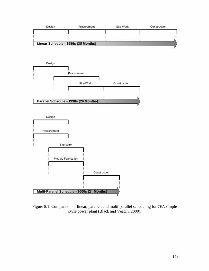
149
Figure 8.1: Comparison of linear, parallel, and multi-parallel scheduling for 7FA simple cycle power plant (Black and Veatch, 2000).
150
Furthermore, this project is unique in several ways. First, this project was designed and
planned based on inherited knowledge from a previous successful project “Doswell
Power Plant Project”. Lessons learnt from the Doswell project were recorded, analyzed
and improved upon by the design and the construction teams. These lessons under went
further examination before they were incorporated in the Calhoun project. Second, the
same teams that designed, procured, and constructed the Doswell project were assigned
to the Calhoun project. Third, both projects use similar power generation technology,
“Simple-Cycle generation technology”. The Doswell project consisted of one simple-
cycle machine; while the Calhoun project is more complex with four simple-cycle
machines. Two of the four simple-cycle machines will eventually be converted to a
“Combined-Cycle Power Plant”.
We chose this very specific, yet complex example of construction operations as test bed
for the development and validation of the developed construction modeling system for
several reasons: First, the assembly problem is very narrow and well known. Therefore, a
limited and reusable number of modeling objects can be easily developed. Secondly, our
goal is to validate and demonstrate by example the potential use of the developed
taxonomy to model construction operations. Thus, a very intuitive example with a short
learning phase is required.
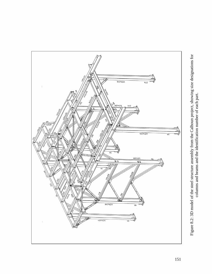
151
Figu
re 8
.2: 3
D m
odel
of t
he st
eel s
truct
ure
asse
mbl
y fr
om th
e C
alho
un p
roje
ct, s
how
ing
size
des
igna
tions
for
colu
mns
and
bea
ms a
nd th
e id
entif
icat
ion
num
ber o
f eac
h pa
rt.
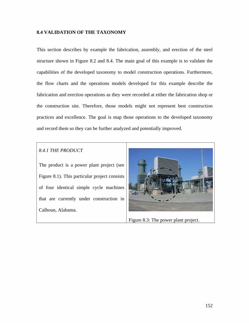
152
8.4 VALIDATION OF THE TAXONOMY
This section describes by example the fabrication, assembly, and erection of the steel
structure shown in Figure 8.2 and 8.4. The main goal of this example is to validate the
capabilities of the developed taxonomy to model construction operations. Furthermore,
the flow charts and the operations models developed for this example describe the
fabrication and erection operations as they were recorded at either the fabrication shop or
the construction site. Therefore, those models might not represent best construction
practices and excellence. The goal is map those operations to the developed taxonomy
and record them so they can be further analyzed and potentially improved.
8.4.1 THE PRODUCT
The product is a power plant project (see
Figure 8.1). This particular project consists
of four identical simple cycle machines
that are currently under construction in
Calhoun, Alabama.
Figure 8.3: The power plant project.
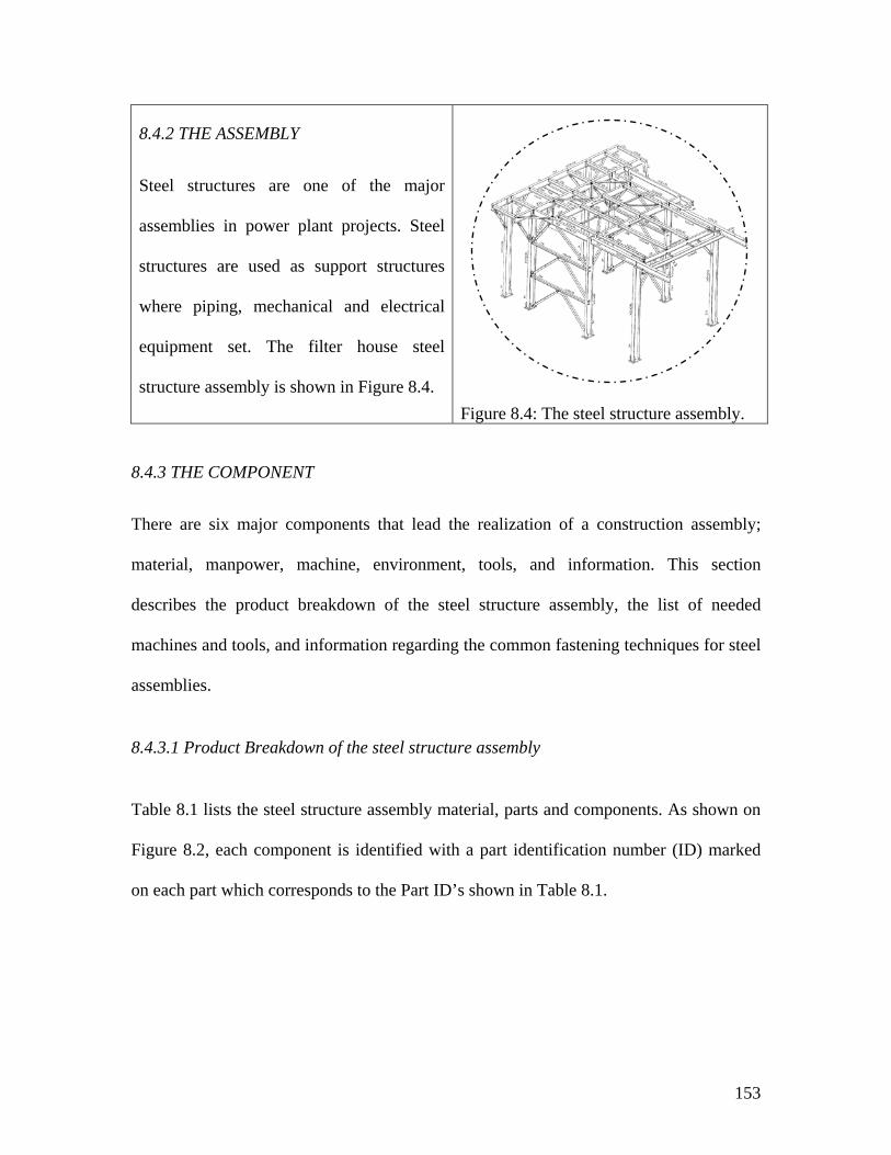
153
8.4.2 THE ASSEMBLY
Steel structures are one of the major
assemblies in power plant projects. Steel
structures are used as support structures
where piping, mechanical and electrical
equipment set. The filter house steel
structure assembly is shown in Figure 8.4.
Figure 8.4: The steel structure assembly.
8.4.3 THE COMPONENT
There are six major components that lead the realization of a construction assembly;
material, manpower, machine, environment, tools, and information. This section
describes the product breakdown of the steel structure assembly, the list of needed
machines and tools, and information regarding the common fastening techniques for steel
assemblies.
8.4.3.1 Product Breakdown of the steel structure assembly
Table 8.1 lists the steel structure assembly material, parts and components. As shown on
Figure 8.2, each component is identified with a part identification number (ID) marked
on each part which corresponds to the Part ID’s shown in Table 8.1.
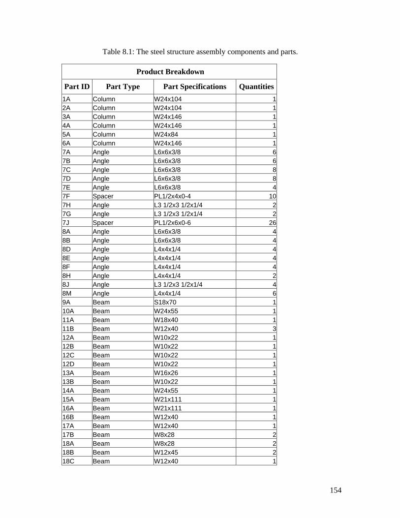
154
Table 8.1: The steel structure assembly components and parts.
Product Breakdown
Part ID Part Type Part Specifications Quantities1A Column W24x104 12A Column W24x104 13A Column W24x146 14A Column W24x146 15A Column W24x84 16A Column W24x146 17A Angle L6x6x3/8 67B Angle L6x6x3/8 67C Angle L6x6x3/8 87D Angle L6x6x3/8 87E Angle L6x6x3/8 47F Spacer PL1/2x4x0-4 107H Angle L3 1/2x3 1/2x1/4 27G Angle L3 1/2x3 1/2x1/4 27J Spacer PL1/2x6x0-6 268A Angle L6x6x3/8 48B Angle L6x6x3/8 48D Angle L4x4x1/4 48E Angle L4x4x1/4 48F Angle L4x4x1/4 48H Angle L4x4x1/4 28J Angle L3 1/2x3 1/2x1/4 48M Angle L4x4x1/4 69A Beam S18x70 110A Beam W24x55 111A Beam W18x40 111B Beam W12x40 312A Beam W10x22 112B Beam W10x22 112C Beam W10x22 112D Beam W10x22 113A Beam W16x26 113B Beam W10x22 114A Beam W24x55 115A Beam W21x111 116A Beam W21x111 116B Beam W12x40 117A Beam W12x40 117B Beam W8x28 218A Beam W8x28 218B Beam W12x45 218C Beam W12x40 1
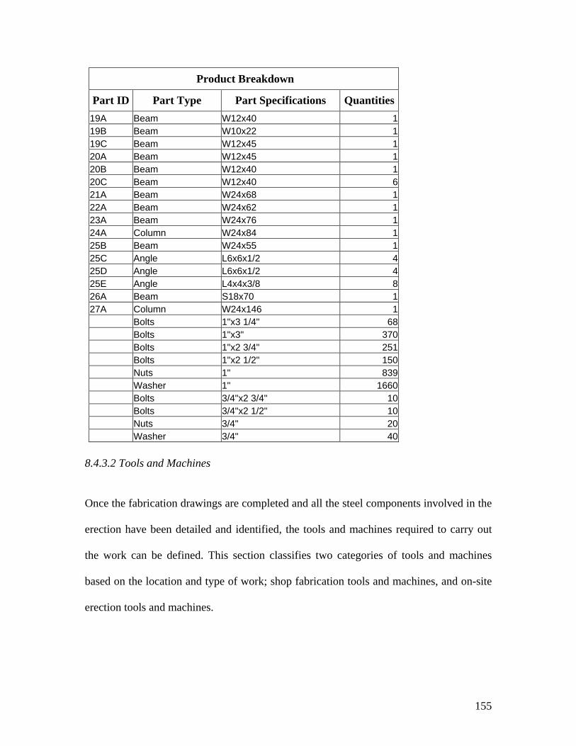
155
Product Breakdown
Part ID Part Type Part Specifications Quantities19A Beam W12x40 119B Beam W10x22 119C Beam W12x45 120A Beam W12x45 120B Beam W12x40 120C Beam W12x40 621A Beam W24x68 122A Beam W24x62 123A Beam W24x76 124A Column W24x84 125B Beam W24x55 125C Angle L6x6x1/2 425D Angle L6x6x1/2 425E Angle L4x4x3/8 826A Beam S18x70 127A Column W24x146 1 Bolts 1"x3 1/4" 68 Bolts 1"x3" 370 Bolts 1"x2 3/4" 251 Bolts 1"x2 1/2" 150 Nuts 1" 839 Washer 1" 1660 Bolts 3/4"x2 3/4" 10 Bolts 3/4"x2 1/2" 10 Nuts 3/4" 20 Washer 3/4" 40
8.4.3.2 Tools and Machines
Once the fabrication drawings are completed and all the steel components involved in the
erection have been detailed and identified, the tools and machines required to carry out
the work can be defined. This section classifies two categories of tools and machines
based on the location and type of work; shop fabrication tools and machines, and on-site
erection tools and machines.
156
Shop fabrication tools and machines
The production lines in fabrication shops are usually organized in such a way that the
material will pass through a one way system from receipt to final dispatch of material.
Most fabrication shops are equipped with overhead traveling cranes or mechanized
conveyer systems. Other tools and equipment may include:
• Crane equipped with chains and hooks, or cranes on conveyors with magnetic lifting
devices.
• Measuring and marking tools.
• Cutting machines: circular saw, band saw, motor operated hacksaw, flame cutting,
and laser cutting.
• Drilling machines, for example radial drilling machine.
• Surface machining and paint spraying machines and paint brushes.
On-site erection tools and machines
Cranes are considered the major piece of equipment for steel erection. Hoisting
equipment of suitable capacity need to be available for any preassemblies, which must be
lifted. The part that requires the greatest lifting capacity and the site conditions
determines the minimum crane capacity to be used. Other tools and equipment that are
required for on-site erection work may include:
• Cranes of various types.
• Bolting equipment, such as spanners, ratchet spanners, torque wrenches, etc.
• Welding equipment.
• Electric generators.
157
• Hydraulic Jacks.
• Measuring equipment such as levels, and laser equipment.
• Handling tools.
• Air compressors.
• Transport equipment
• Miscellaneous equipment such as pulleys, spreader beams, etc.
• Wire ropes, hoisting slings, shackles, etc.
• Paint spraying machines and paint brushes.
8.4.3.3 Manpower
Manpower can be determined in terms of personnel required to complete the erection of
the structure.
8.4.3.4 Environment
The shop fabrication and the construction site are the two major environments that
control the fabrication and erection of steel assemblies. The fabrication shop can be
organized as a production line where most operations can be executed in controlled and
standardized fashion. On the other hand, work performed at the construction site may be
slowed down by adverse weather.
8.4.3.5 Information
Part of the information needed to complete the erection operation is the fastening
techniques for steel structures. Steel elements can be joined together with any of three
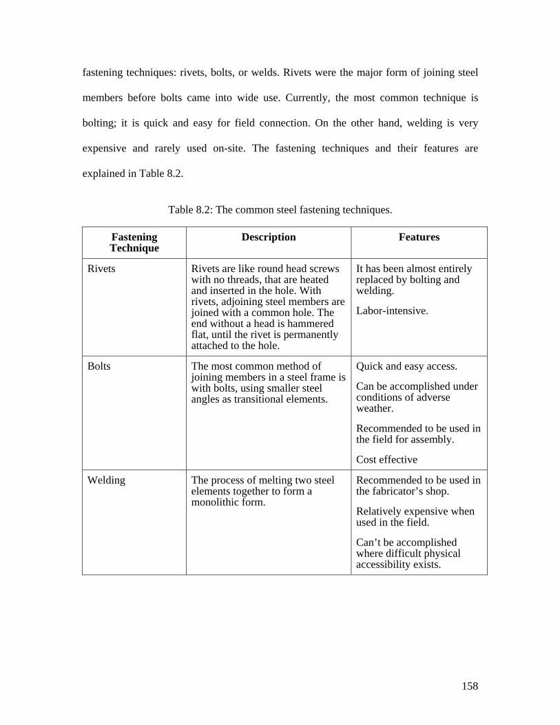
158
fastening techniques: rivets, bolts, or welds. Rivets were the major form of joining steel
members before bolts came into wide use. Currently, the most common technique is
bolting; it is quick and easy for field connection. On the other hand, welding is very
expensive and rarely used on-site. The fastening techniques and their features are
explained in Table 8.2.
Table 8.2: The common steel fastening techniques.
Fastening Technique
Description Features
Rivets Rivets are like round head screws with no threads, that are heated and inserted in the hole. With rivets, adjoining steel members are joined with a common hole. The end without a head is hammered flat, until the rivet is permanently attached to the hole.
It has been almost entirely replaced by bolting and welding.
Labor-intensive.
Bolts The most common method of joining members in a steel frame is with bolts, using smaller steel angles as transitional elements.
Quick and easy access.
Can be accomplished under conditions of adverse weather.
Recommended to be used in the field for assembly.
Cost effective
Welding The process of melting two steel elements together to form a monolithic form.
Recommended to be used in the fabricator’s shop.
Relatively expensive when used in the field.
Can’t be accomplished where difficult physical accessibility exists.
159
8.4.4 OPERATION
Figure 8.5 describes the general nature and the sequence of work that takes place at the
design office, the fabrication shop, and the construction site. Typically, the engineering
office issues the engineering drawings and technical specifications of the steel structure
to the fabricator to commence fabrication. Then the fabricator prepares detailed
fabrication drawings and erection sequences. The fabricator role is to transfer ‘raw’
material into finished products that can be easily assembled on-site. Also, the fabricator
preassembles and assembles steel parts and components to reduce the amount of work to
be done on-site.
The fabrication and delivery schedule is coordinated with the erection schedule and the
capacity of the site erection team. The site erection team coordinates and handles the
unloading of the fabricated elements. Then the erection starts as soon as the foundations
and the anchor bolts are checked. The next two sections will provide further details
regarding the operations needed for the fabrication and erection of the steel structure
assembly as they occur either at the fabrication shop or the construction site.
8.4.4.1 The fabrication shop operations
As depicted in Figure 8.6, the basic flow of fabrication activities at the shop can be
visualized as a tunnel for the main flow of major operations.
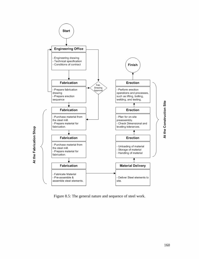
160
Figure 8.5: The general nature and sequence of steel work.
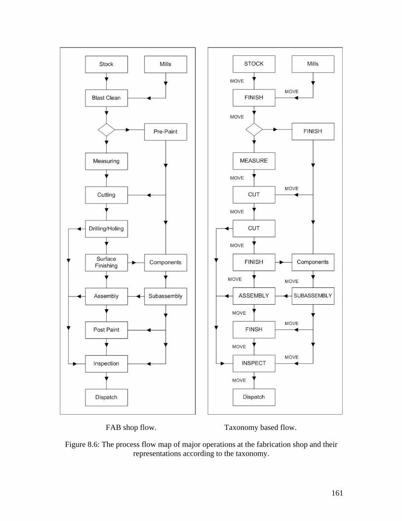
161
FAB shop flow. Taxonomy based flow.
Figure 8.6: The process flow map of major operations at the fabrication shop and their representations according to the taxonomy.
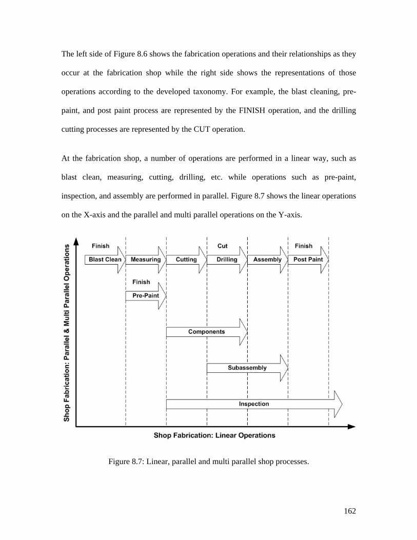
162
The left side of Figure 8.6 shows the fabrication operations and their relationships as they
occur at the fabrication shop while the right side shows the representations of those
operations according to the developed taxonomy. For example, the blast cleaning, pre-
paint, and post paint process are represented by the FINISH operation, and the drilling
cutting processes are represented by the CUT operation.
At the fabrication shop, a number of operations are performed in a linear way, such as
blast clean, measuring, cutting, drilling, etc. while operations such as pre-paint,
inspection, and assembly are performed in parallel. Figure 8.7 shows the linear operations
on the X-axis and the parallel and multi parallel operations on the Y-axis.
Figure 8.7: Linear, parallel and multi parallel shop processes.
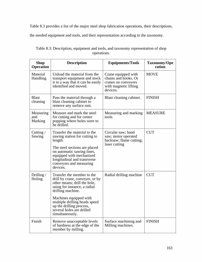
163
Table 8.3 provides a list of the major steel shop fabrication operations, their descriptions,
the needed equipment and tools, and their representation according to the taxonomy.
Table 8.3: Description, equipment and tools, and taxonomy representation of shop operations.
Shop Operation
Description Equipments/Tools Taxonomy/Operation
Material Handling
Unload the material from the transport equipment and stock it in a way that it can be easily identified and moved.
Crane equipped with chains and hooks. Or cranes on conveyors with magnetic lifting devices.
MOVE
Blast cleaning
Pass the material through a blast cleaning cabinet to remove any surface rust.
Blast cleaning cabinet. FINISH
Measuring and Marking
Measure and mark the steel for cutting and for center popping where holes were to be drilled.
Measuring and marking tools
MEASURE
Cutting / Sawing
Transfer the material to the sawing station for cutting to length.
The steel sections are placed on automatic sawing lines, equipped with mechanized longitudinal and transverse conveyors and measuring devices.
Circular saw; band saw; motor operated hacksaw; flame cutting; laser cutting
CUT
Drilling / Holing
Transfer the member to the drill by crane, conveyer, or by other means; drill the hole, using for instance, a radial drilling machine.
Machines equipped with multiple drilling heads speed up the drilling process, several holes are drilled simultaneously.
Radial drilling machine CUT
Finish Remove unacceptable levels of hardness at the edge of the member by milling.
Surface machining and Milling machines.
FINISH
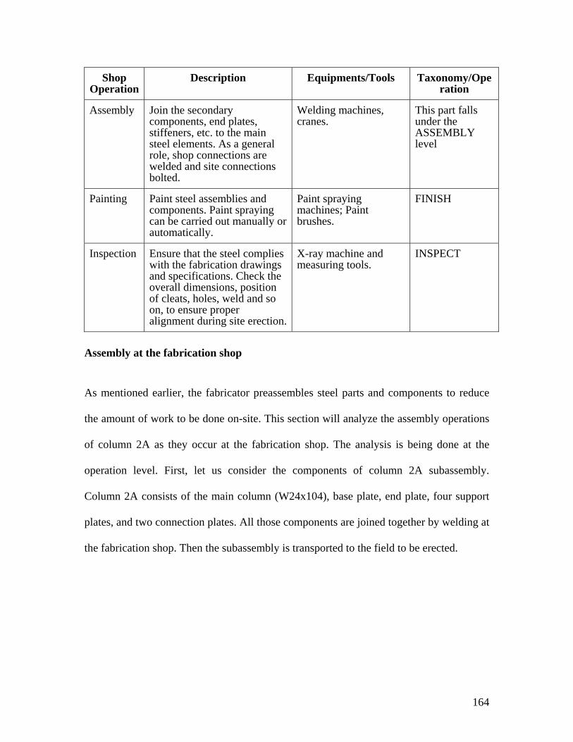
164
Shop Operation
Description Equipments/Tools Taxonomy/Operation
Assembly Join the secondary components, end plates, stiffeners, etc. to the main steel elements. As a general role, shop connections are welded and site connections bolted.
Welding machines, cranes.
This part falls under the ASSEMBLY level
Painting Paint steel assemblies and components. Paint spraying can be carried out manually or automatically.
Paint spraying machines; Paint brushes.
FINISH
Inspection Ensure that the steel complies with the fabrication drawings and specifications. Check the overall dimensions, position of cleats, holes, weld and so on, to ensure proper alignment during site erection.
X-ray machine and measuring tools.
INSPECT
Assembly at the fabrication shop
As mentioned earlier, the fabricator preassembles steel parts and components to reduce
the amount of work to be done on-site. This section will analyze the assembly operations
of column 2A as they occur at the fabrication shop. The analysis is being done at the
operation level. First, let us consider the components of column 2A subassembly.
Column 2A consists of the main column (W24x104), base plate, end plate, four support
plates, and two connection plates. All those components are joined together by welding at
the fabrication shop. Then the subassembly is transported to the field to be erected.
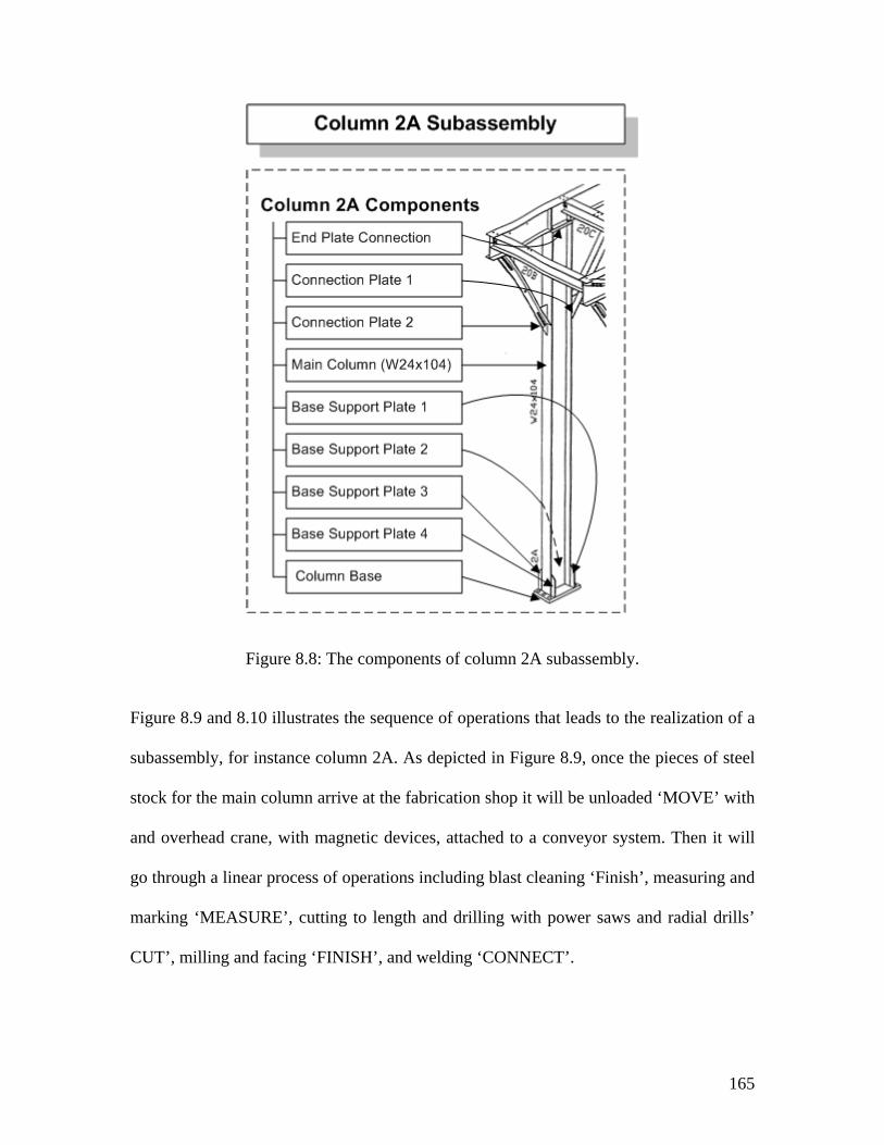
165
Figure 8.8: The components of column 2A subassembly.
Figure 8.9 and 8.10 illustrates the sequence of operations that leads to the realization of a
subassembly, for instance column 2A. As depicted in Figure 8.9, once the pieces of steel
stock for the main column arrive at the fabrication shop it will be unloaded ‘MOVE’ with
and overhead crane, with magnetic devices, attached to a conveyor system. Then it will
go through a linear process of operations including blast cleaning ‘Finish’, measuring and
marking ‘MEASURE’, cutting to length and drilling with power saws and radial drills’
CUT’, milling and facing ‘FINISH’, and welding ‘CONNECT’.
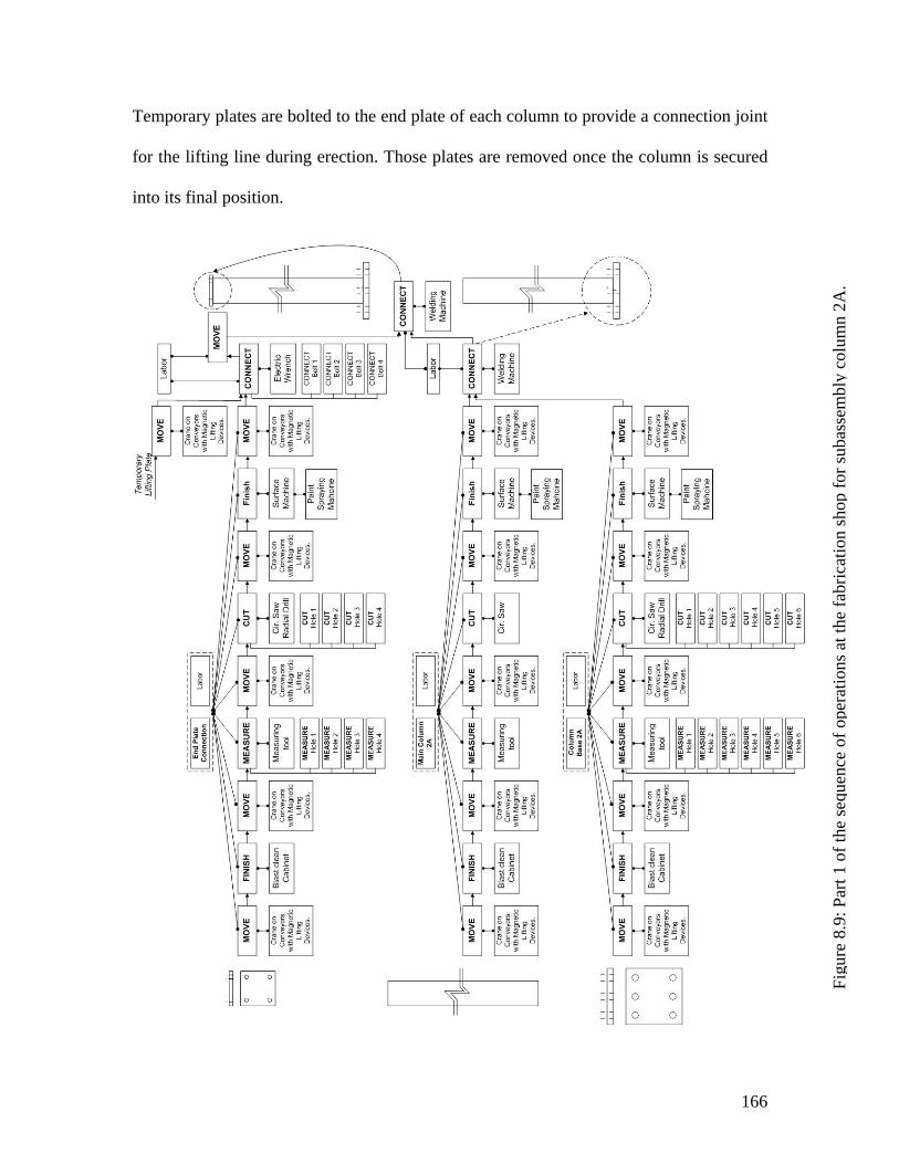
166
Temporary plates are bolted to the end plate of each column to provide a connection joint
for the lifting line during erection. Those plates are removed once the column is secured
into its final position.
Figu
re 8
.9: P
art 1
of t
he se
quen
ce o
f ope
ratio
ns a
t the
fabr
icat
ion
shop
for s
ubas
sem
bly
colu
mn
2A.
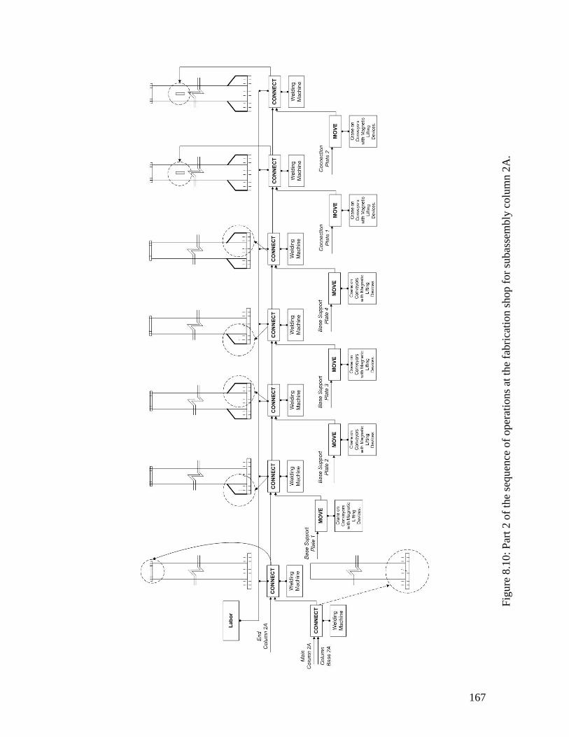
167
Figu
re 8
.10:
Par
t 2 o
f the
sequ
ence
of o
pera
tions
at t
he fa
bric
atio
n sh
op fo
r sub
asse
mbl
y co
lum
n 2A
.
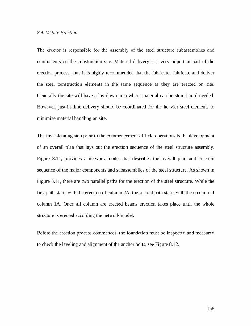
168
8.4.4.2 Site Erection
The erector is responsible for the assembly of the steel structure subassemblies and
components on the construction site. Material delivery is a very important part of the
erection process, thus it is highly recommended that the fabricator fabricate and deliver
the steel construction elements in the same sequence as they are erected on site.
Generally the site will have a lay down area where material can be stored until needed.
However, just-in-time delivery should be coordinated for the heavier steel elements to
minimize material handling on site.
The first planning step prior to the commencement of field operations is the development
of an overall plan that lays out the erection sequence of the steel structure assembly.
Figure 8.11, provides a network model that describes the overall plan and erection
sequence of the major components and subassemblies of the steel structure. As shown in
Figure 8.11, there are two parallel paths for the erection of the steel structure. While the
first path starts with the erection of column 2A, the second path starts with the erection of
column 1A. Once all column are erected beams erection takes place until the whole
structure is erected according the network model.
Before the erection process commences, the foundation must be inspected and measured
to check the leveling and alignment of the anchor bolts, see Figure 8.12.
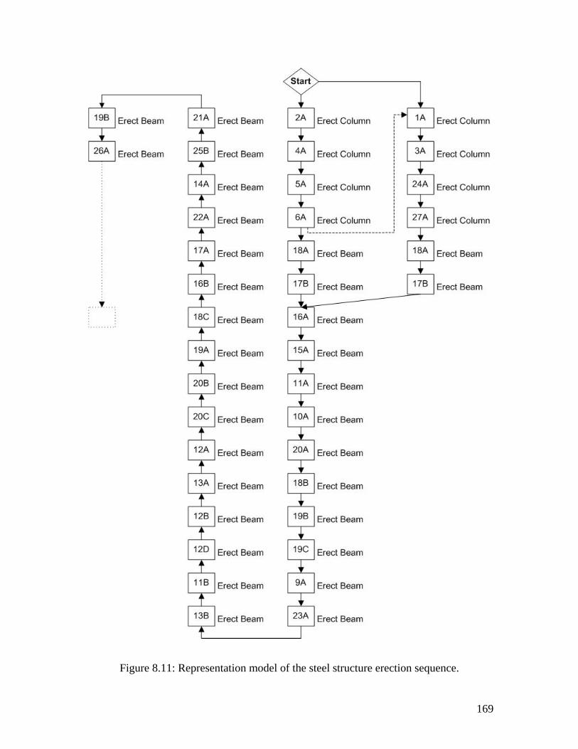
169
Figure 8.11: Representation model of the steel structure erection sequence.
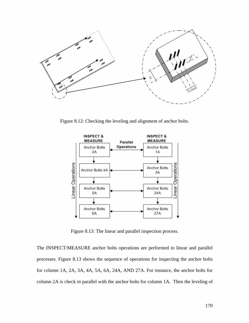
170
Figure 8.12: Checking the leveling and alignment of anchor bolts.
Figure 8.13: The linear and parallel inspection process.
The INSPECT/MEASURE anchor bolts operations are performed in linear and parallel
processes. Figure 8.13 shows the sequence of operations for inspecting the anchor bolts
for column 1A, 2A, 3A, 4A, 5A, 6A, 24A, AND 27A. For instance, the anchor bolts for
column 2A is check in parallel with the anchor bolts for column 1A. Then the leveling of
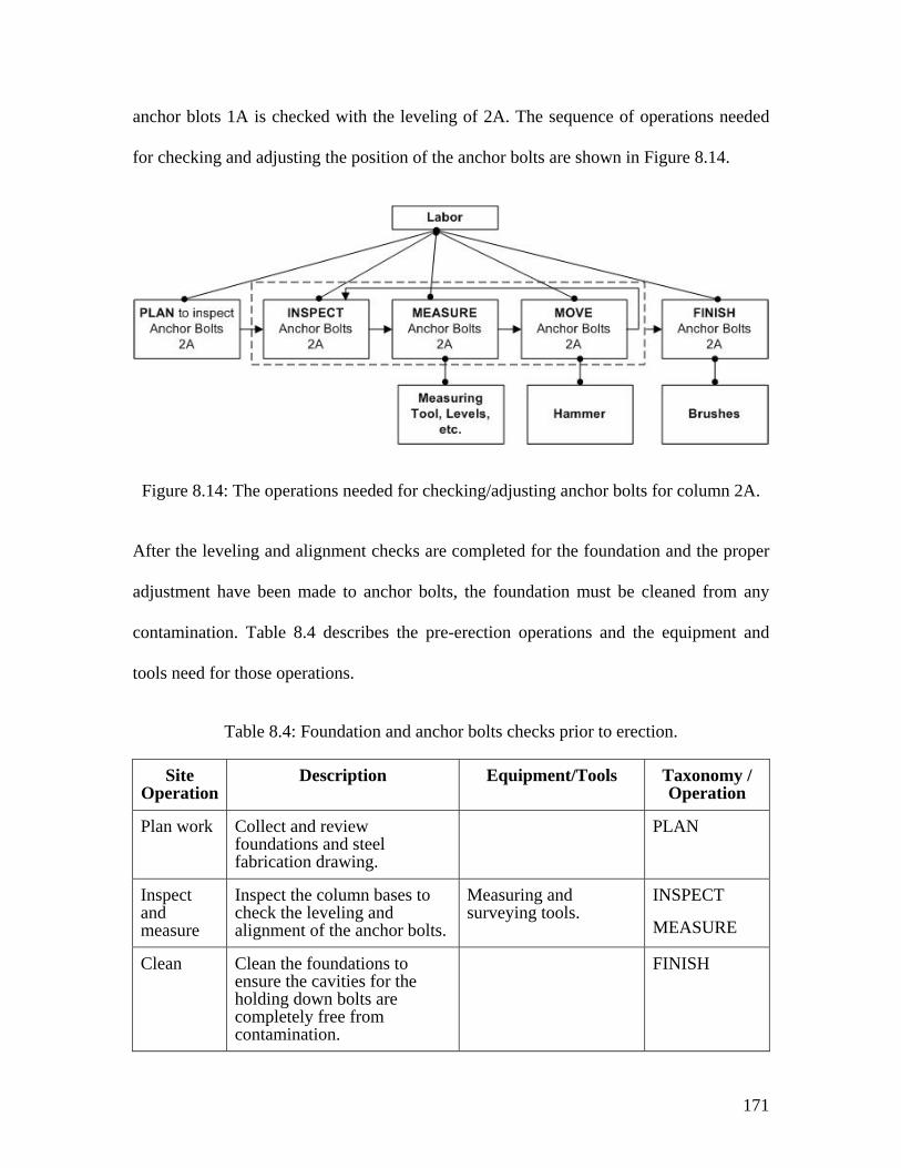
171
anchor blots 1A is checked with the leveling of 2A. The sequence of operations needed
for checking and adjusting the position of the anchor bolts are shown in Figure 8.14.
Figure 8.14: The operations needed for checking/adjusting anchor bolts for column 2A.
After the leveling and alignment checks are completed for the foundation and the proper
adjustment have been made to anchor bolts, the foundation must be cleaned from any
contamination. Table 8.4 describes the pre-erection operations and the equipment and
tools need for those operations.
Table 8.4: Foundation and anchor bolts checks prior to erection.
Site Operation
Description Equipment/Tools Taxonomy / Operation
Plan work Collect and review foundations and steel fabrication drawing.
PLAN
Inspect and measure
Inspect the column bases to check the leveling and alignment of the anchor bolts.
Measuring and surveying tools.
INSPECT
MEASURE
Clean Clean the foundations to ensure the cavities for the holding down bolts are completely free from contamination.
FINISH
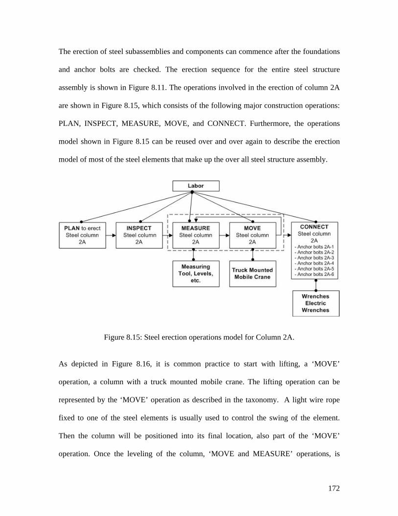
172
The erection of steel subassemblies and components can commence after the foundations
and anchor bolts are checked. The erection sequence for the entire steel structure
assembly is shown in Figure 8.11. The operations involved in the erection of column 2A
are shown in Figure 8.15, which consists of the following major construction operations:
PLAN, INSPECT, MEASURE, MOVE, and CONNECT. Furthermore, the operations
model shown in Figure 8.15 can be reused over and over again to describe the erection
model of most of the steel elements that make up the over all steel structure assembly.
Figure 8.15: Steel erection operations model for Column 2A.
As depicted in Figure 8.16, it is common practice to start with lifting, a ‘MOVE’
operation, a column with a truck mounted mobile crane. The lifting operation can be
represented by the ‘MOVE’ operation as described in the taxonomy. A light wire rope
fixed to one of the steel elements is usually used to control the swing of the element.
Then the column will be positioned into its final location, also part of the ‘MOVE’
operation. Once the leveling of the column, ‘MOVE and MEASURE’ operations, is
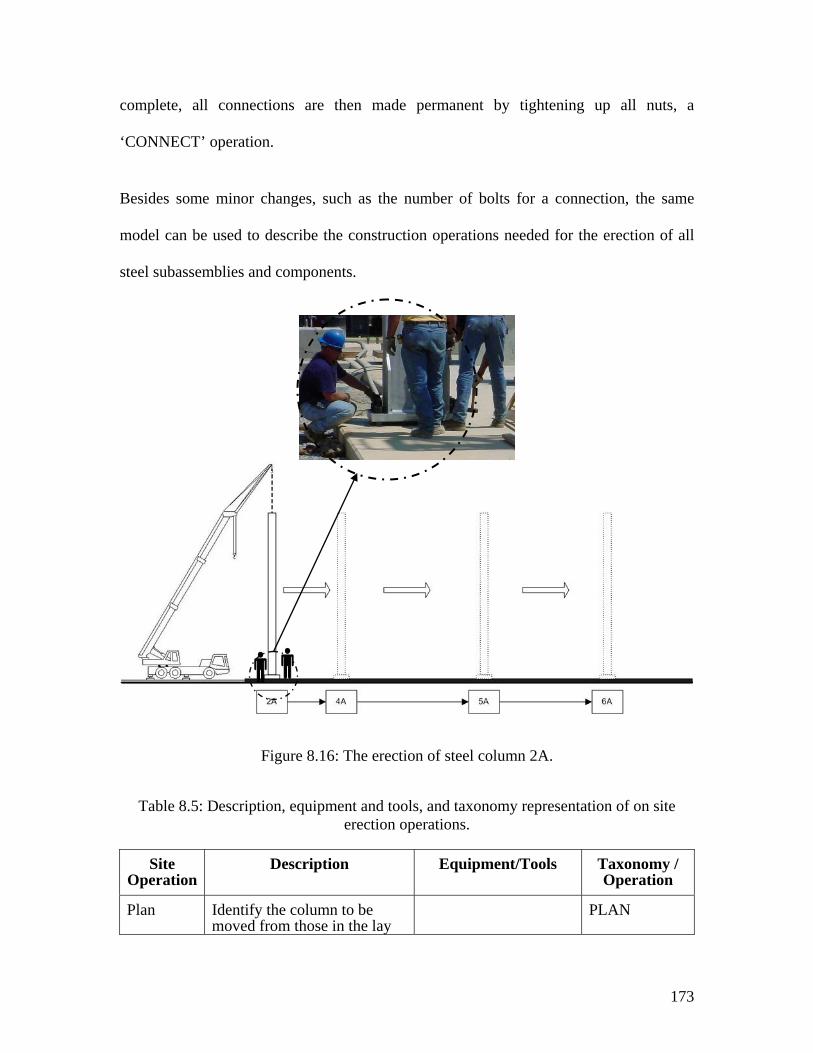
173
complete, all connections are then made permanent by tightening up all nuts, a
‘CONNECT’ operation.
Besides some minor changes, such as the number of bolts for a connection, the same
model can be used to describe the construction operations needed for the erection of all
steel subassemblies and components.
Figure 8.16: The erection of steel column 2A.
Table 8.5: Description, equipment and tools, and taxonomy representation of on site erection operations.
Site Operation
Description Equipment/Tools Taxonomy / Operation
Plan Identify the column to be moved from those in the lay
PLAN

174
Site Operation
Description Equipment/Tools Taxonomy / Operation
down area.
Inspect & measure
Inspect and measure steel element.
Measuring tools INSPECT
MEASURE
Place Move a steel element from the storage area to its final position according the erection drawings.
The MOVE operations including the following: drop the crane hooks to the column; attach the hooks to the column; lift, swing, place the column; and position the beam into the final position.
Mobile crane
Transport equipment
MOVE
Inspect Check the bolts, nuts, and washers against the drawings. They must be exactly as indicated on the fabrication drawings and they must be clean and undamaged.
Visual inspection INSPECT
Move Install bolts exact location and position in drilled holes.
Torque wrench MOVE
Move Insert a hardened steel washer under the nut.
MOVE
Move Position the nuts over the washer.
MOVE
Connect Connect the nuts by rotating them around the bolts. Don’t tighten the nuts to allow members flexibility.
Torque wrench CONNECT
The focus of this example was to describe the fabrication, assembly, and erection of the
steel structure, shown in Figure 8.2 and 8.4, as they occur at the fabrication shop and the
construction site. The intention was to illustrate by example that the proposed taxonomy
is capable of describing and modeling the needed construction operations and processes
to complete the erection of the steel structure. Thus the flow charts and the process
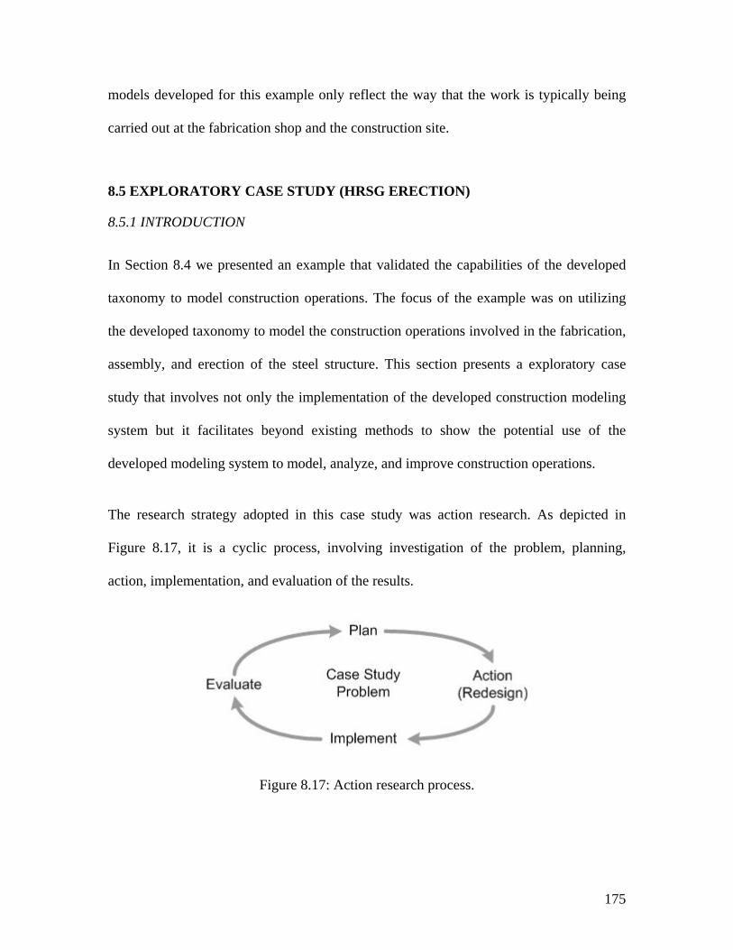
175
models developed for this example only reflect the way that the work is typically being
carried out at the fabrication shop and the construction site.
8.5 EXPLORATORY CASE STUDY (HRSG ERECTION)
8.5.1 INTRODUCTION
In Section 8.4 we presented an example that validated the capabilities of the developed
taxonomy to model construction operations. The focus of the example was on utilizing
the developed taxonomy to model the construction operations involved in the fabrication,
assembly, and erection of the steel structure. This section presents a exploratory case
study that involves not only the implementation of the developed construction modeling
system but it facilitates beyond existing methods to show the potential use of the
developed modeling system to model, analyze, and improve construction operations.
The research strategy adopted in this case study was action research. As depicted in
Figure 8.17, it is a cyclic process, involving investigation of the problem, planning,
action, implementation, and evaluation of the results.
Figure 8.17: Action research process.
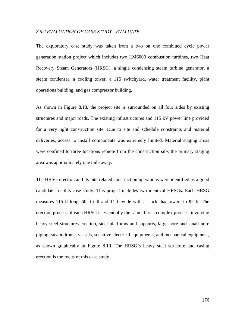
176
8.5.2 EVALUATION OF CASE STUDY - EVALUATE
The exploratory case study was taken from a two on one combined cycle power
generation station project which includes two LM6000 combustion turbines, two Heat
Recovery Steam Generators (HRSG), a single condensing steam turbine generator, a
steam condenser, a cooling tower, a 115 switchyard, water treatment facility, plant
operations building, and gas compressor building.
As shown in Figure 8.18, the project site is surrounded on all four sides by existing
structures and major roads. The existing infrastructures and 115 kV power line provided
for a very tight construction site. Due to site and schedule constraints and material
deliveries, access to install components was extremely limited. Material staging areas
were confined to three locations remote from the construction site; the primary staging
area was approximately one mile away.
The HRSG erection and its interrelated construction operations were identified as a good
candidate for this case study. This project includes two identical HRSGs. Each HRSG
measures 115 ft long, 60 ft tall and 11 ft wide with a stack that towers to 92 ft. The
erection process of each HRSG is essentially the same. It is a complex process, involving
heavy steel structures erection, steel platforms and supports, large bore and small bore
piping, steam drums, vessels, sensitive electrical equipments, and mechanical equipment,
as shown graphically in Figure 8.19. The HRSG’s heavy steel structure and casing
erection is the focus of this case study.
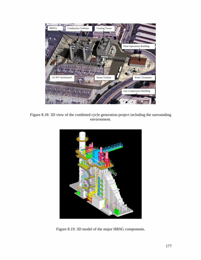
177
115 KV Switchyard
HRSGs Cooling Tower
Steam Turbine Water Treatment
Gas Compressors Building
Plant Operations Building
Combustion Turbines
Figure 8.18: 3D view of the combined cycle generation project including the surrounding environment.
Figure 8.19: 3D model of the major HRSG components.
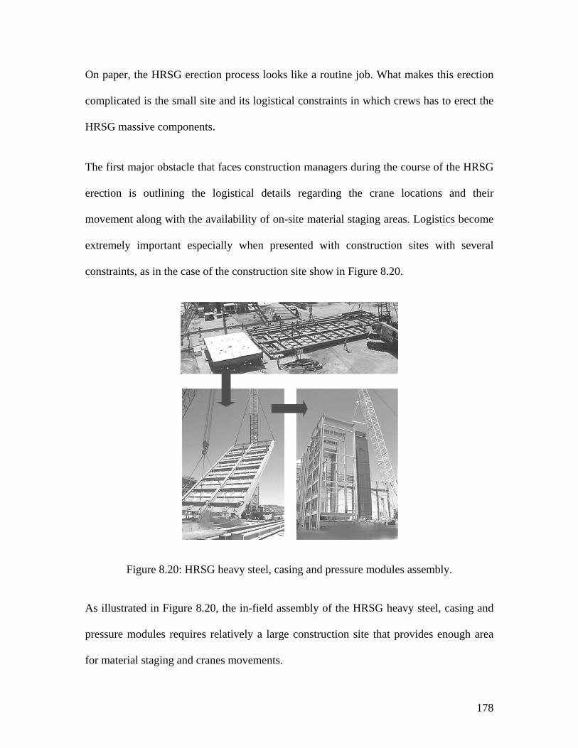
178
On paper, the HRSG erection process looks like a routine job. What makes this erection
complicated is the small site and its logistical constraints in which crews has to erect the
HRSG massive components.
The first major obstacle that faces construction managers during the course of the HRSG
erection is outlining the logistical details regarding the crane locations and their
movement along with the availability of on-site material staging areas. Logistics become
extremely important especially when presented with construction sites with several
constraints, as in the case of the construction site show in Figure 8.20.
Figure 8.20: HRSG heavy steel, casing and pressure modules assembly.
As illustrated in Figure 8.20, the in-field assembly of the HRSG heavy steel, casing and
pressure modules requires relatively a large construction site that provides enough area
for material staging and cranes movements.
179
The second major obstacle is the constant demand to shorten the construction schedule in
order to meet the market need. In an effort to overcome some of the obstacles a thorough
understanding of the HRSG design and erection processes is needed. This can be
achieved by utilizing the developed taxonomy to model, evaluate, and select HRSG
prototypes that will potentially improve the in-field HRSG construction operations.
8.5.3 CASE STUDY GOALS - PLAN
In order to improve the in-field HRSG construction operations and produce a value
adding models it was necessary to be as realistic as possible. Before starting any
modeling analysis of the HRSG erection, the overall goals of the model were determined.
The goals served as the modeling objectives throughout the modeling course of this case
study. The goals are outlined as follows: Minimize material handling at the construction
site, reduce the overall project schedule, maximize efficiency, and maximize
concurrency.
8.5.4 PRODUCT BREAKDOWN STRUCTURE
One of the most useful tools of the developed taxonomy is the ability to model
construction operations at several levels of details to form a hierarchy. By linking one
model to another you create a parent-child relationship. Changes applied to the child are
also transmitted to the parent. By linking more models to both parent and child models
complex hierarchies can be created to represent complex construction operations.
This section provides an overview of the product breakdown structure of the project
chosen to illustrate the use of hierarchical modeling. The development of the product
180
breakdown structure is a dynamic process that evolves into a more meaningful structure
in conjunction with the development and analysis of the construction operations models.
In other words, the development processes of the product breakdown structure and their
associated the construction operations models are mutually linked. The rational behind
this approach is in order to improve product delivery in general and construction
operations in specific an effective integration is required between construction operations
and design processes of product, assemblies and components. The developed taxonomy
supports this rational.
The product is a combined cycle power plant that was divided into eight main assemblies:
(1) HRSG, (2) combustion turbines, (3) cooling tower, (4) steam turbine, (5) water
treatment facility, (6) gas compressors, (7) plant operations building, and (8) switchyard.
The HRSG assembly was broken-down into of subassemblies of which the HRSG main
steel structure and ducts were the focus of this case study. Several alternatives for
modeling the HRSG main steel structure and ducts sub-assemblies were considered by
the researcher and the most promising alternative was selected. The selected alternative
calls for dividing the HRSG main steel structure and ducts into ten sub-subassemblies, as
illustrated in Figure 8.21. Furthermore, each one of the ten sub-subassemblies was broken
down into major components. Several design alternatives of the sub-assemblies
components were also examined. Figure 8.22 illustrates the major components for HRSG
subassembly 01-01-08.
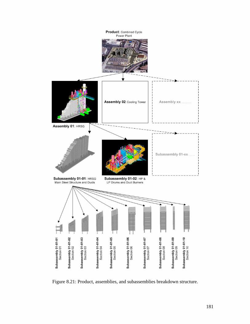
181
Figure 8.21: Product, assemblies, and subassemblies breakdown structure.
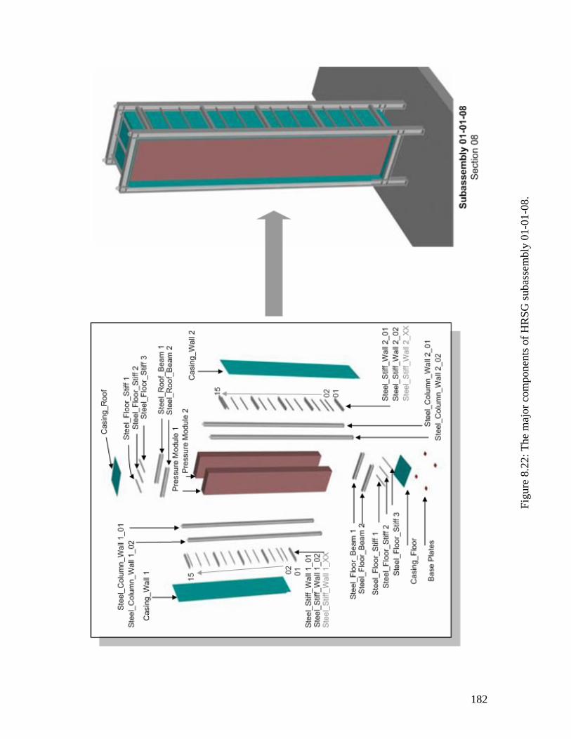
182
Figu
re 8
.22:
The
maj
or c
ompo
nent
s of H
RSG
suba
ssem
bly
01-0
1-08
.
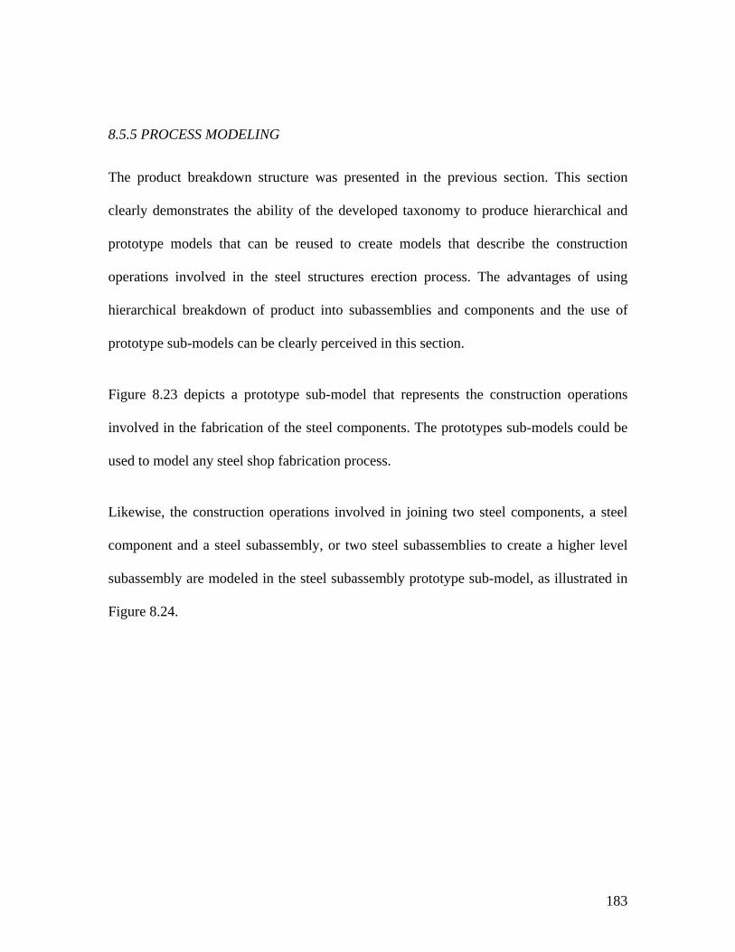
183
8.5.5 PROCESS MODELING
The product breakdown structure was presented in the previous section. This section
clearly demonstrates the ability of the developed taxonomy to produce hierarchical and
prototype models that can be reused to create models that describe the construction
operations involved in the steel structures erection process. The advantages of using
hierarchical breakdown of product into subassemblies and components and the use of
prototype sub-models can be clearly perceived in this section.
Figure 8.23 depicts a prototype sub-model that represents the construction operations
involved in the fabrication of the steel components. The prototypes sub-models could be
used to model any steel shop fabrication process.
Likewise, the construction operations involved in joining two steel components, a steel
component and a steel subassembly, or two steel subassemblies to create a higher level
subassembly are modeled in the steel subassembly prototype sub-model, as illustrated in
Figure 8.24.
184
Figu
re 8
.23:
Typ
ical
stee
l com
pone
nt su
b-m
odel
.
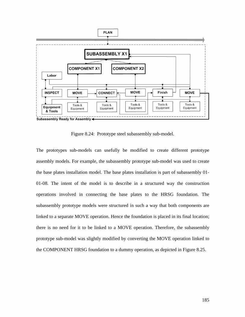
185
Figure 8.24: Prototype steel subassembly sub-model.
The prototypes sub-models can usefully be modified to create different prototype
assembly models. For example, the subassembly prototype sub-model was used to create
the base plates installation model. The base plates installation is part of subassembly 01-
01-08. The intent of the model is to describe in a structured way the construction
operations involved in connecting the base plates to the HRSG foundation. The
subassembly prototype models were structured in such a way that both components are
linked to a separate MOVE operation. Hence the foundation is placed in its final location;
there is no need for it to be linked to a MOVE operation. Therefore, the subassembly
prototype sub-model was slightly modified by converting the MOVE operation linked to
the COMPONENT HRSG foundation to a dummy operation, as depicted in Figure 8.25.
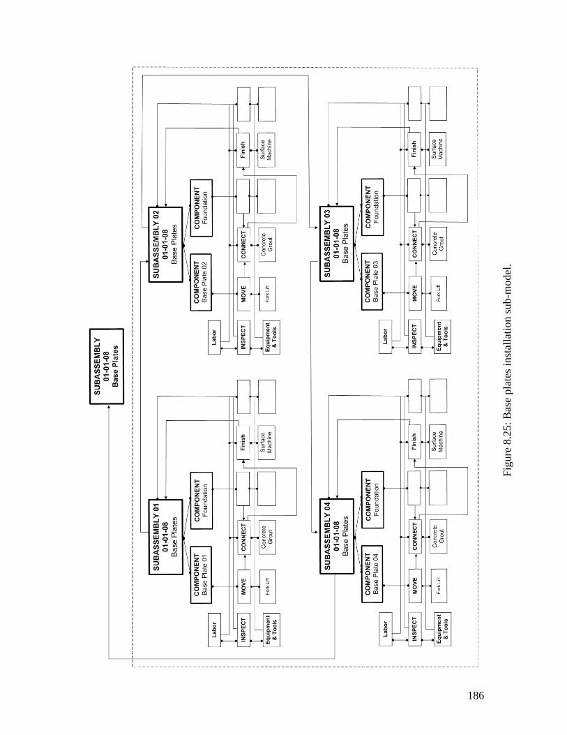
186
Figu
re 8
.25:
Bas
e pl
ates
inst
alla
tion
sub-
mod
el.
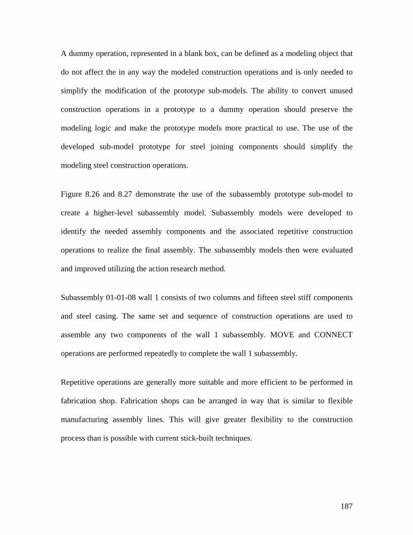
187
A dummy operation, represented in a blank box, can be defined as a modeling object that
do not affect the in any way the modeled construction operations and is only needed to
simplify the modification of the prototype sub-models. The ability to convert unused
construction operations in a prototype to a dummy operation should preserve the
modeling logic and make the prototype models more practical to use. The use of the
developed sub-model prototype for steel joining components should simplify the
modeling steel construction operations.
Figure 8.26 and 8.27 demonstrate the use of the subassembly prototype sub-model to
create a higher-level subassembly model. Subassembly models were developed to
identify the needed assembly components and the associated repetitive construction
operations to realize the final assembly. The subassembly models then were evaluated
and improved utilizing the action research method.
Subassembly 01-01-08 wall 1 consists of two columns and fifteen steel stiff components
and steel casing. The same set and sequence of construction operations are used to
assemble any two components of the wall 1 subassembly. MOVE and CONNECT
operations are performed repeatedly to complete the wall 1 subassembly.
Repetitive operations are generally more suitable and more efficient to be performed in
fabrication shop. Fabrication shops can be arranged in way that is similar to flexible
manufacturing assembly lines. This will give greater flexibility to the construction
process than is possible with current stick-built techniques.
188
Figu
re 8
.26:
Wal
l 1 o
f sub
asse
mbl
y 01
-01-
08 e
rect
ion
sub-
mod
el.
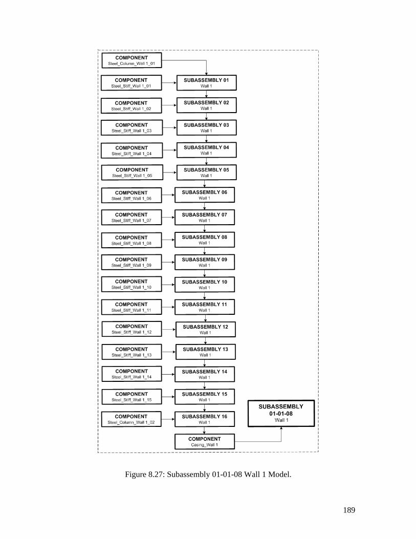
189
Figure 8.27: Subassembly 01-01-08 Wall 1 Model.
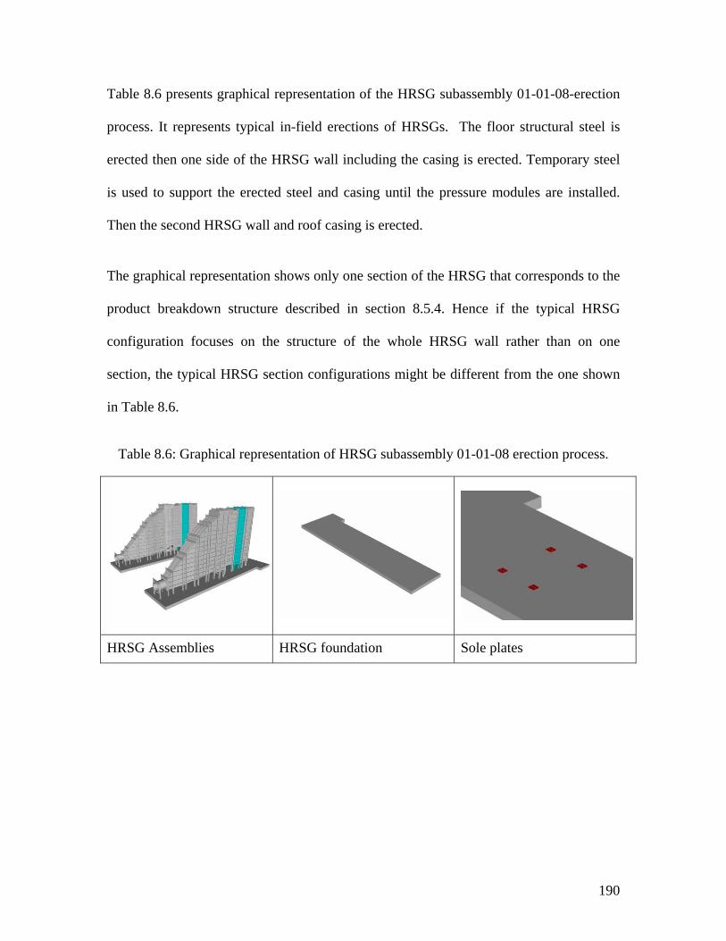
190
Table 8.6 presents graphical representation of the HRSG subassembly 01-01-08-erection
process. It represents typical in-field erections of HRSGs. The floor structural steel is
erected then one side of the HRSG wall including the casing is erected. Temporary steel
is used to support the erected steel and casing until the pressure modules are installed.
Then the second HRSG wall and roof casing is erected.
The graphical representation shows only one section of the HRSG that corresponds to the
product breakdown structure described in section 8.5.4. Hence if the typical HRSG
configuration focuses on the structure of the whole HRSG wall rather than on one
section, the typical HRSG section configurations might be different from the one shown
in Table 8.6.
Table 8.6: Graphical representation of HRSG subassembly 01-01-08 erection process.
HRSG Assemblies HRSG foundation Sole plates
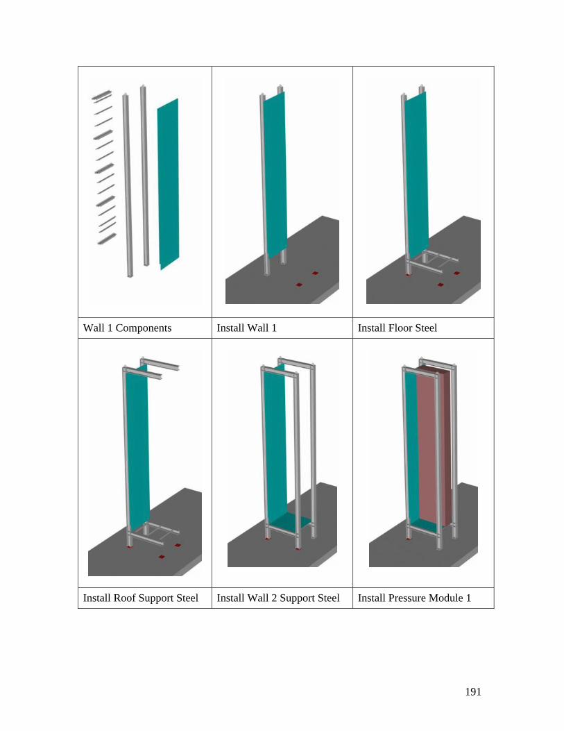
191
Wall 1 Components Install Wall 1 Install Floor Steel
Install Roof Support Steel Install Wall 2 Support Steel Install Pressure Module 1
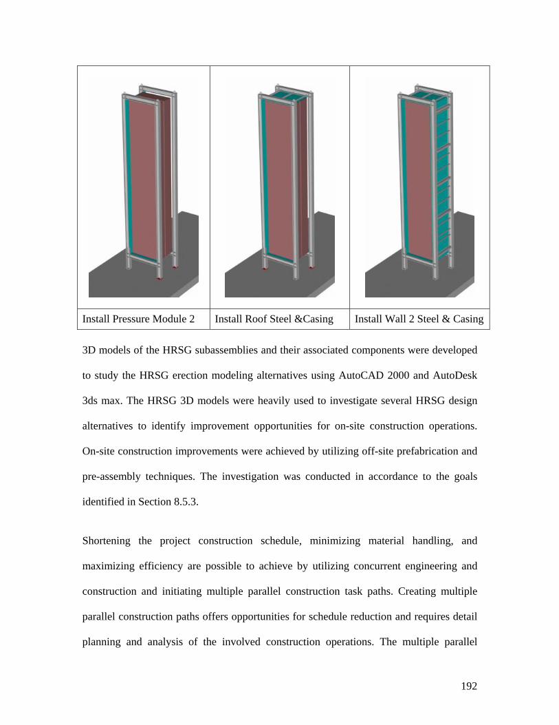
192
Install Pressure Module 2 Install Roof Steel &Casing Install Wall 2 Steel & Casing
3D models of the HRSG subassemblies and their associated components were developed
to study the HRSG erection modeling alternatives using AutoCAD 2000 and AutoDesk
3ds max. The HRSG 3D models were heavily used to investigate several HRSG design
alternatives to identify improvement opportunities for on-site construction operations.
On-site construction improvements were achieved by utilizing off-site prefabrication and
pre-assembly techniques. The investigation was conducted in accordance to the goals
identified in Section 8.5.3.
Shortening the project construction schedule, minimizing material handling, and
maximizing efficiency are possible to achieve by utilizing concurrent engineering and
construction and initiating multiple parallel construction task paths. Creating multiple
parallel construction paths offers opportunities for schedule reduction and requires detail
planning and analysis of the involved construction operations. The multiple parallel
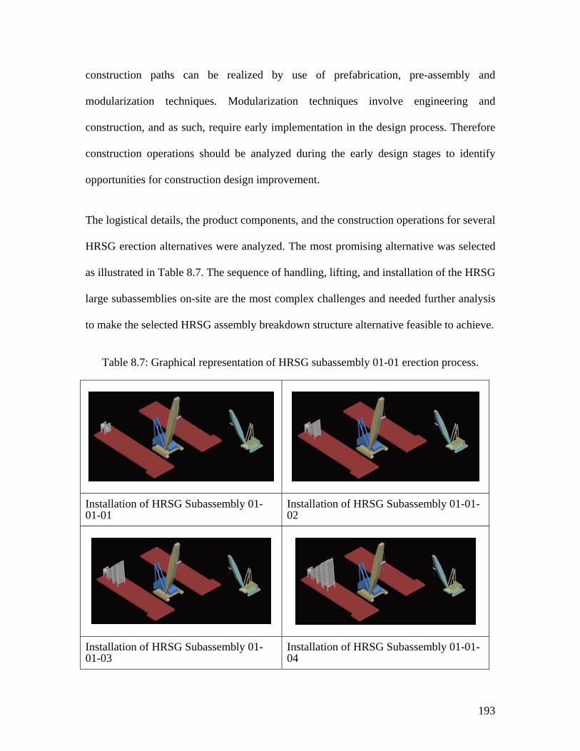
193
construction paths can be realized by use of prefabrication, pre-assembly and
modularization techniques. Modularization techniques involve engineering and
construction, and as such, require early implementation in the design process. Therefore
construction operations should be analyzed during the early design stages to identify
opportunities for construction design improvement.
The logistical details, the product components, and the construction operations for several
HRSG erection alternatives were analyzed. The most promising alternative was selected
as illustrated in Table 8.7. The sequence of handling, lifting, and installation of the HRSG
large subassemblies on-site are the most complex challenges and needed further analysis
to make the selected HRSG assembly breakdown structure alternative feasible to achieve.
Table 8.7: Graphical representation of HRSG subassembly 01-01 erection process.
Installation of HRSG Subassembly 01-01-01
Installation of HRSG Subassembly 01-01-02
Installation of HRSG Subassembly 01-01-03
Installation of HRSG Subassembly 01-01-04
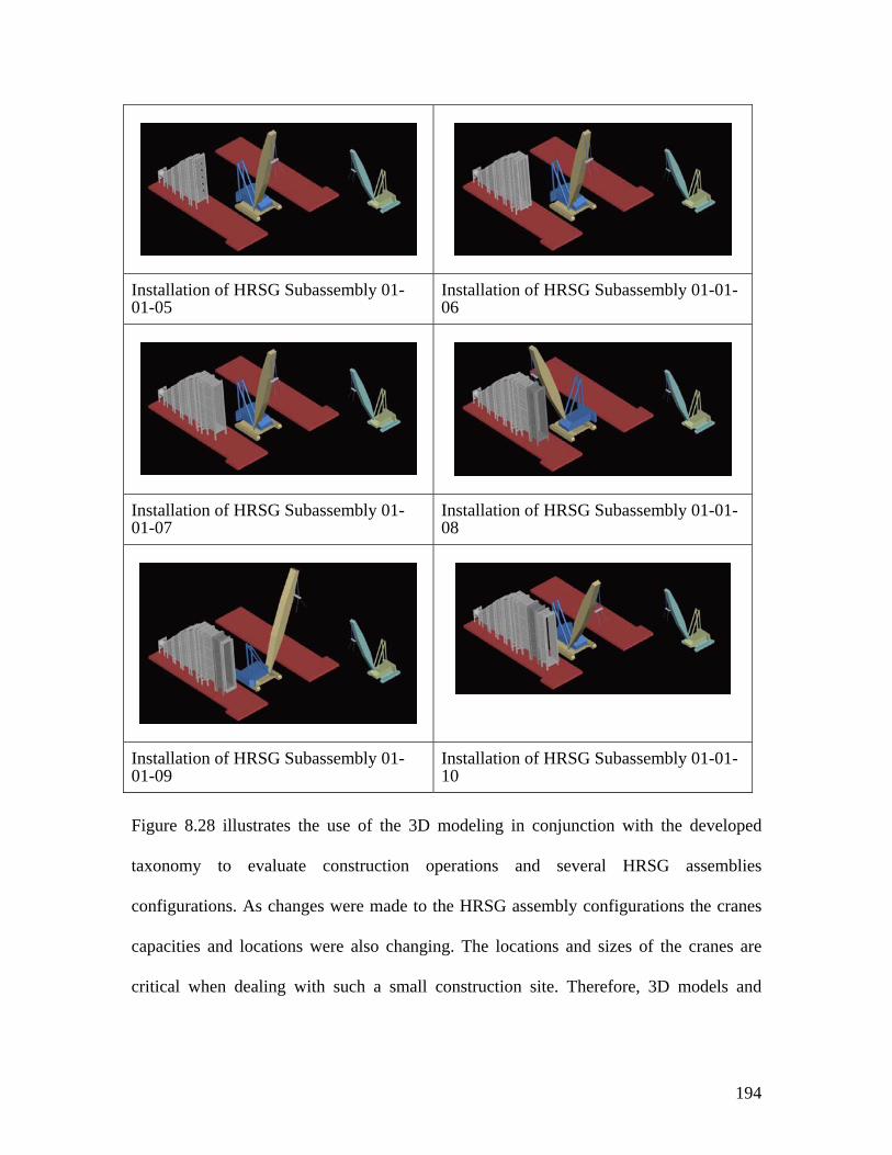
194
Installation of HRSG Subassembly 01-01-05
Installation of HRSG Subassembly 01-01-06
Installation of HRSG Subassembly 01-01-07
Installation of HRSG Subassembly 01-01-08
Installation of HRSG Subassembly 01-01-09
Installation of HRSG Subassembly 01-01-10
Figure 8.28 illustrates the use of the 3D modeling in conjunction with the developed
taxonomy to evaluate construction operations and several HRSG assemblies
configurations. As changes were made to the HRSG assembly configurations the cranes
capacities and locations were also changing. The locations and sizes of the cranes are
critical when dealing with such a small construction site. Therefore, 3D models and
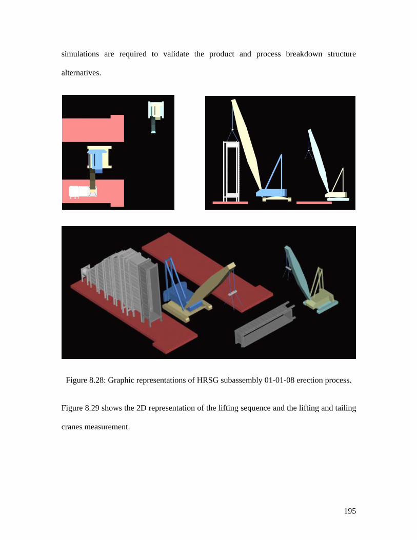
195
simulations are required to validate the product and process breakdown structure
alternatives.
Figure 8.28: Graphic representations of HRSG subassembly 01-01-08 erection process.
Figure 8.29 shows the 2D representation of the lifting sequence and the lifting and tailing
cranes measurement.
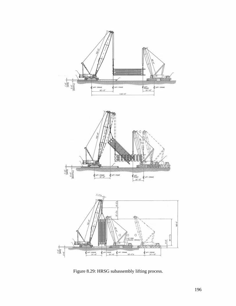
196
Figure 8.29: HRSG subassembly lifting process.
197
The simulation and modeling analysis showed that prefabrication and pre-assembly
operations could be performed off-site. This significantly reduces the number of
repetitive field erection operations to the point where only few on-site operations are
needed to complete the erection of the HRSG main steel and ducts.
The larger HRSG assemblies create new connection schemes that can be evaluated and
analyzed to identify opportunities for on-site construction automation. For example,
joining the assemblies could be automated by using robotic welding machines.
The main conclusion drawn from the HRSG model development and analysis is that
improvement to construction operations requires detail modeling of construction
processes and rethinking the design and engineering process, with the goal of improving
the overall project delivery in mind. The developed taxonomy supports this goal by
providing a structured construction language to model and analyze construction
operations at several level of detail. In addition, the developed taxonomy enhanced the
environment for modeling, analyzing, and integrating the total engineering, procurement,
and construction phases of a project. Furthermore, by utilizing the developed modeling
system some barriers between engineering and in-field construction can be lifted
allowing improvement of construction operations to optimize the design, procurement,
and fabrication process.
Additional modeling and analysis are needed to further improve the final construction
operations involved in the HRSG main steel frame erection. This work initiated the
realization of the usefulness of the developed taxonomy to model, analyze, and improve
on-site construction operation. The developed case studies have validated with great
198
confidence the potential use of the modeling system as a direct support tool for improving
construction.
The finding of this case study is just the tip of iceberg. Ultimately, the construction
industry will realize the need for such a modeling system to record, analyze, and improve
construction operations, especially when standardization and modularization concepts are
profoundly employed by the construction industry.
8.6 SYNOPSIS
Chapter Eight provides two practical case studies that validate and demonstrate the
capabilities and potential uses of the developed taxonomy. The first case study describes
the modeling process of the fabrication, assembly, and erection of a steel structure. The
fabrication and erection processes are presented as they occur at either the fabrication
shop or at the construction site. Product and process breakdown structures are also
presented. The second exploratory case study shows the potential uses of the developed
system to model, analyze, and improve the construction operations involved in HRSG
erection. Further, Chapter Eight clearly demonstrates the capabilities of the developed
taxonomy to generate hierarchical and prototypical models that can be used multiple
times to describe the operations involved in any steel structures erection. 3D models of
the HRSG assemblies are developed and heavily used to investigate several HRSG design
alternatives and identify improvement opportunities for on-site construction operations.
Improvements are realized by initiating multiple parallel construction paths utilizing
modularization, off-site prefabrication, and pre-assembly techniques.
199
CHAPTER NINE: SUMMARY, CONCLUSION, AND RECOMMENDATION FOR FUTURE RESEARCH
9.1 SUMMARY
During the course of this research, and in writing this dissertation, there are some
background factors that have been borne in mind. One is that identifying and narrowing
the scope of work of the researched subject. Because of the wide variety of the subjects
that requires immediate research attention in construction, the proposed scope of work at
the early stages of this research development was too large to be addressed in one
dissertation. Most researchers are ambitious and devote their effort to ask and answer all
the questions in their field of study and continually strive to resolve most of the problems
to and increase the level of understanding add value to the body of knowledge. Likewise,
this research started with a broad subject and with the goal of improving the way we do
construction today.
Motivated to find a way to improve construction, this research went through several
considerations and reviews that included but not limited to topics such as construction
200
modeling and simulation techniques, construction means and methods, physically-based
modeling techniques, virtual reality modeling environments, construction automation and
robotics, construction products and processes, and construction classification systems.
The reviews focused on identifying the state of current research in the aforementioned
subjects and to determine how they can be utilized to achieve the objectives of the
research in this dissertation.
As the research moved forward, it became apparent that all the aforementioned research
subjects are essential components of the total effort to improve construction; however,
what was missing is a common denominator that links these technologies and areas of
knowledge together and provide a standard mean of communication among the
construction industry. The common denominator is a common construction language that
provides the needed classification structure to represent construction products,
assemblies, operations, etc. From this point forward the research direction was shifted to
focus on the development of a common construction taxonomy that can be used for
modeling, capturing, analyzing, and potentially improving construction operations.
The development of the common taxonomy was challenging and required identification
and investigation of the major categories of knowledge related to construction operations
modeling and representations. These types of knowledge were identified and researched
as follows:
Modeling and simulation: In Chapter Two, general modeling and simulation systems that
are popular in the construction community are described. Also, an overview of the
current state of modeling and simulation techniques is presented.
201
Physically-based modeling: Chapter Three presents physically-based modeling
techniques and their connections to the developed taxonomy. Literature on the
applications of physically-based modeling techniques were found to be limited, therefore
applications from other fields, such as mechanical engineering, industrial engineering,
and computer graphics are also reviewed. Additionally, this chapter establishes the
advantages of applying physically-based techniques to construction modeling
applications.
Virtual environments: Chapter Four reviews the fundamentals of virtual environments
and the application of virtual and 4D-CAD modeling approaches in construction. The
advantages and limitations of these approaches in relation to the developed modeling
system in this research are identified. Virtual environments are identified as excellent
representation medium for visualizing construction operations.
Automation and robotics in construction: In Chapter Five, the potential uses of robotics
and automation opportunities in construction are discussed. Also, the distribution of work
between humans and tools and equipment based on their physical and information
contributions are presented.
Classification of construction work: Chapter Six presents and analyzes construction work
classifications at different levels of detail. The main purpose of the analyses is to identify
which construction operations can be usefully modeled and the appropriate level of the
model. Therefore, various classification methods that are used to identify automation
opportunities in construction are examined. In addition, the product and process
breakdown structures in manufacturing operations are reviewed.
202
The common taxonomy: In Chapter Seven, a common taxonomy for modeling
construction operations is developed. First, the taxonometric hierarchy consists of seven
levels of classification: product, assemblies and subassemblies, components, operations,
processes, physics, and control. The seven hierarchical levels are established by
examining the ways that construction field operations are being carried out. Second, six
major blocks of construction knowledge are identified and information about the
interaction processes that is required to model construction operations in a logical way
are described. Third, schemes for modeling information in the construction domain such
as aecXML and IFC’s are presented. Then the developed taxonomy is partially mapped to
the IFC standards to identify where both systems intersect or overlap and their
advantages and limitations. Fourth, areas of potential concurrency between the design
process and the developed taxonometric structure are presented. Also, a new concurrent
classification structure is developed to usefully facilitate the use of such a structure
during the various stages of design. The new concurrent classification structure
distinguishes between two categories of design and construction phases: product-oriented
phases and process-oriented phases. Finally, this chapter investigates the adaptability of
the developed modeling system by increasing the scope of accountability to include
cradle-to-cradle responsibility. Design chemistry and design for disassembly are
discussed and an example for the disassembly of a steel structure is presented.
Exploratory case studies: Chapter Eight provides two practical case studies that validate
and demonstrate the capabilities and potential uses of the developed taxonomy. The first
case study describes the modeling process of the fabrication, assembly, and erection of a
steel structure. The fabrication and erection processes are presented as they occur at
203
either the fabrication shop or at the construction site. Product and process breakdown
structures are also presented. The second exploratory case study shows the potential uses
of the developed system to model, analyze, and improve the construction operations
involved in HRSG erection.
Further, Chapter Eight clearly demonstrates the capabilities of the developed taxonomy to
generate hierarchical and prototypical models that can be used multiple times to describe
the operations involved in any steel structures erection. 3D models of the HRSG
assemblies are developed and heavily used to investigate several HRSG design
alternatives and identify improvement opportunities for on-site construction operations.
Improvements are realized by initiating multiple parallel construction paths utilizing
modularization, off-site prefabrication, and pre-assembly techniques.
In conclusion, this research introduces a new common taxonomy for modeling
construction operations. This taxonomy applies a combination of techniques and
knowledge from different areas to improve modeling and analysis of operations and
consists of seven levels: product, assemblies and subassemblies, components, operations,
processes, physics, and control. The hierarchical levels were established by exploring the
ways construction field operations are carried out. Moreover, based on action research
techniques, two practical case studies were developed in order to validate the capabilities
of the common taxonomy. The order in which the taxonomy and the case studies were
conducted provided the basis for conceiving the new modeling technique that is designed
to usefully describe, capture, and analyze the diverse elements of construction operations.
204
This research confirmed the necessity for a common construction language so that
improvements to complex construction operations and processes may be achieved. The
examples introduced and examined have given us great confidence in the use of the
developed taxonomy as a direct support language for enhancing the modeling of
construction operations.
9.2 RECOMMENDATION FOR FUTURE RESEARCH
The research presented in this dissertation is only a step towards the creation of a
common construction taxonomy that can be usefully used to model, capture and analyze
construction operations. Since the developed taxonomy uses knowledge from many
different areas, there is plenty of room for improvement and further work can proceed in
many directions.
First, further enhancement to the developed taxonomy is an area with considerable
research potential. The developed examples presented in Chapter 8 have shown that the
developed taxonomy can successfully be used in modeling complex construction
operations. However, further usability studies of the developed taxonomy are needed to
realize its full potential in standardizing a structured construction modeling language.
Further enhancement of the developed taxonomy could follow several paths.
1. Applying the developed taxonomy to broader range of construction operations to
further validate its capabilities and to address the importance of its modeling
structure. Chapter Eight presented two prototypes examples of construction
applications that are related to the erection of steel structures. Additional
205
construction applications should be identified for further modeling and analysis
such as, piping installation, cable pulling, etc.
2. Concentrating on certain levels within the developed taxonomy that may be
considered for automation. For example, automate the modeling requirements at
the process, physics and controls levels. Some of the processes and their related
physical properties might be suitable for automation. For example, automate the
required modeling processes to complete a MOVE operation for a steel member.
Further investigation is required to identify the tasks or level that are suitable for
automation. Furthermore, a controlled automation approach is required as well to
maintain the integrity of the modeling system.
3. Integrating the developed taxonomy with product design processes during the
various design stages is another research path. Chapter Seven introduced a
framework that identifies areas of potential concurrency between the design
process and developed taxonomy. A concurrent approach could explicitly draw in
the considerations of construction, using advanced construction technologies or
traditional methods, into the earliest design stages. The concurrent analysis of the
design and construction of a product and the explicit of its subsequent
construction operations may reveal new concepts that ease and improve the way
we do construction today. Therefore, more in depth studies are required to
concurrently integrate the design of products and processes at the various levels of
the developed taxonomy.
206
A second research direction is to concentrate on the development of a construction
computer-modeling environment that allows the development of construction operations
models utilizing the developed taxonometric structure. This modeling environment is
needed to further validate and test the flexibility and effectiveness of the developed
taxonomy and to identify opportunities for improvements. This dissertation provides the
basis and identifies a broad set of requirements that such modeling environment must
posses in order to be successfully applied to modeling of construction operations:
1. The modeling environment should be a computer base system that uses an object-
oriented programming language with the objective of providing a standard
modeling environment that is based on the developed taxonomy and its structured
construction language.
2. As discussed in Chapter Four and building on the review of previous works on
computer modeling and simulation for construction, this research identifies virtual
systems as the most promising modeling environments that have considerable
potential in simulating complicated construction operations. Therefore a virtual
environment for modeling construction operations is needed.
3. The user interface should support graphical representations and should be the
primary mean of model development. The modeling environment should allow
users to build models of construction operations in an intuitive and user-friendly
manner. However, advanced users should still be able to access and develop
extension tools to accommodate their modeling needs. Further investigations are
needed to determine the guideline for developing a suitable user interface.
207
4. Since the developed taxonomy is hierarchical in nature, the architecture of this
modeling environment should have a hierarchical structure as well.
5. The modeling environment must be able to exchange information with existing
AEC applications in order to reduce the data entry requirements as well as to
generate information for use by existing AEC applications. Therefore, further
investigation of means for exchanging information within the AEC applications is
needed. Chapter Seven identifies the industry foundation classes as the most
promising building data models that have the potential to successfully provide the
means for exchanging information with the AEC applications.
6. The modeling environment should support the use of prototype libraries to
encourage the reusability of existing models. The objective of the prototype
libraries is to serve as a general, reusable, and extensible tool that can be usefully
used to construct models of construction objects and operations. Chapter Three
introduces the concept of prototype libraries and its use for constructing
physically-based models of graphical objects. Further research in how to construct
and apply prototype libraries within the proposed environment is needed.
Third, the developed taxonomy was structured mainly to model and capture construction
operations. Therefore, modeling the disassembly process of constructed facilities is
another subject with considerable potential for a future research that could expand the
scope of the developed taxonomy. Chapter Seven provided examples that show the
potential use of the developed taxonomy to model the operations involved in the
disassembly process of a steel structure. More in-depth evaluation of the disassembly

208
processes is needed to understand what knowledge is important and how it can be
modeled.
209
BIBLIOGRAPHY
1. AbouRizk, S. M., D. W. Haplin and J. D. Lutz (1992). State of the Art in Construction Simulation. Proceedings of the 1992 Winter Simulation Conference.
2. AbouRizk, S. M. and Y. Mohamed (2000). SIMPHONY - an Integrated
Environment for Construction Simulation. Proceedings of the 2000 Winter Simulation Conference, Piscataway, New Jersey, Institute of Electrical and Electronics Engineers.
3. ADAMS (2002). http://www.adams.com. 4. aecXML (2003). http://www.aecxml.org. 5. Al-Masalha, S. and R. Wakefield (2000). Design for Construction Utilizing a
Virtual Environment. 8th International Conference on Computing in Civil and Building Engineering, Stanford, California.
6. Anthony, W., F. Steven, M. Blair, M. William and K. Theodore (1996).
“Augmented Reality in Architectural Construction, Inspection, and Renovation.” Computing in Civil Engineering: 913-919.
7. Archiniegas, F. (2001). XML Developer's Guide. New York, McGraw-Hill. 8. Atkin, B. L., P. Atkinson, B. D. Bridgewater and R. D. Wing (1993).
Construction Cladding Jointing Methods: A Guide to Design for Automatic Assembly. Automation and Robotics in Construction X, Houston, Texas, Elsevier.
9. Barsoum, A. S., F. C. Hadipriono and R. E. Larew (1996). “Avoiding Falls
from Scaffolding in Virtual World.” Computing in Civil Engineering: 906-912.
210
10. Barzel, R. (1992). Physically-Based Modeling for Computer Graphics: A
Structured Approach. San Diego, CA, Academic Press, Inc. 11. Bashford, S. F. and W. H. Askew (1992). Initial Task Selection for Detailed
Robotic Evaluation. The 9th ISARC, Japan. 12. Beliveau, Y., S. Dixit and T. Dale (1993). “Dynamic Damping of Payload
Motion.” Journal of Construction Engineering and Management 119(3). 13. Beliveau, Y. J., D. W. Cody and T. H. Mills (1998). “Virtual Visit -
Telecommunication for the Construction Industry.” Journal of Project and Construction Management 4(2): 36-54.
14. Burati, J. L. J., J. J. Farrington and W. B. Ledbetter (1992). “Causes of Quality
Deviations in Design and Construction.” Journal of Construction and Engineering Management 116(2): 239-260.
15. CADSI (1999). Simulation Driven Design. CADSI News, CADSI. 1. 16. Carr, R. I. (1979). “Simulation of Construction Project Duration.” Journal of
the Construction Division, ASCE 105: 117-127. 17. Chang, D. Y. (1986). RESQUE: a Resource Based Simulation System for
Construction Process Planning. Department of Civil Engineering. Ann Arbor, Michigan, University of Michigan.
18. Chapman, P. M. and D. P. M. Wills (1998). Model Analysis: A Physical
Model for Virtual Environments? In Proceedings of Eurographics UK, Leeds University, UK.
19. Cheok, K. C. and R. R. Beck (1996). Computer Visualization of Dynamic
System Motion: Systems Modeling and Computer Simulation. New York, NY, Marcel Dekker Inc.
20. Chrysler (1998). http://www.chrysler.com. 21. Coomans, M. K. D. and R. M. Oxman (1996). Prototyping of Designs in
Virtual Reality. Proceeding of the 3rd Conference on Design and Decision Support Systems in Architecture and Urban Planning, Spa., Belgium.
22. Cremeans, J. E. (1981). “Productivity in Construction Industry.” Construction
Review: 4-6. 23. DADS (1999). DADS 8.5 User's Guide.
211
24. Damrianant, J. (1998). Petri Net-Based Systems for Construction-Process Modeling and Simulation. School of Civil Engineering. Kensington, NSW, Australia, University of New South Wales.
25. Delmia (2003). http://www.delmia.com. 26. Demsetz, L. (1989). Task Identification for Construction Automation. The 6th
ISARC, San Francisco. 27. Durlach, N. I. and A. S. Mavor (1994). Virtual Reality, Scientific and
Technological Challenges, National Academy Press. 28. Edwards, J. and G. Luecke (1996). Physically Based Models for Use in a Force
Feedback Virtual Environment. Proceedings of the Japan USA Symposium on Flexible Automation, Boston Massachusetts, ASME.
29. Ellis, S. R. (1995). Origins and Elements of Virtual Environments. Virtual
Environments and Advanced Interface Design. W. e. a. Barfield, Oxford University Press: 14-57.
30. Engeli, M. and D. Kurmann (1996). “Spatial Objects and Intelligent Agents in
a Virtual Environment.” Automation in Construction 5(3): 141-150. 31. EONReality (2002). http://www.eonreality.com. 32. Everett, J. (1990). Back to Basics in Construction Automation. The 7th
ISARC, London. 33. Everett, J. G. (1991). Construction Automation: Basic Task Selection and
Development of the Cranium. Department of Civil Engineering. Cambridge, Mass., Massachusetts Institute of Technology.
34. Everett, J. G. and A. H. Slocum (1994). “Automation and Robotics
Opportunities: Construction Versus Manufacturing.” Journal of Construction Management Engineering and Management 120: 443-452.
35. Everett, J. G. (1994). Ergonomics, Health, and Safety in Construction:
Opportunities for Automation and Robotics. Automation and Robotics in Construction, Brighton, U.K., Elsevier.
36. Everett, J. G. (1999). “Overexertion Injuries in Construction.” Journal of
Construction Engineering and Management 125(2): 109-114. 37. Fernando, T., K. Kahkonen, J. Leinonen, N. Murray and H. Tawfik (2001).
Facilitation of Collaborative Communication for Building Construction with Virtual Reality Technology. AVR II and CONVR 2001 Conference, Sweden.
212
38. Fischer, M., K. McKinney, K. Jennifer and Howard-Craig (1996). Interactive
4D-CAD. Proc., 3rd Congress on Computing in Civil Engineering, Anaheim, California.
39. Fischer, M. and C. Kam (2002). PM4D Final Report: CIFE Technical Report
Number 143. Stanford, Stanford University. 40. Furness, S. T. A. and W. Barfield (1995). Introduction to Virtual Reality
Environments. Virtual Environments and Advanced Interface Design. W. Barfield, Oxford University Press: 3-13.
41. Gigante, M. A. (1994). Virtual Reality: Definitions, History and Applications.
Virtual Reality Systems. R. A. Earnshaw, Academic Press: 3-14. 42. Gilbreth, F. B. (1972). Motion Study: A Method for Increasing the Efficiency
of the Workman. Easton, Hive Publishing Company. 43. Goldsmith, J. and A. H. Barr (1993). “Applying Constrained Optimization to
Computer Graphics.” SMPTE Journal 102(10): 910-912. 44. Gross, M. (1996). “Why Cannot CAD be More Like Lego? CKB, A Program
for Building Construction Kits.” Automation in Construction 2(5): 285-300. 45. Guo, S.-J. and R. L. Tucker (1993). Automation Needs Determination Using
AHP Approach. Automation and Robotics in Construction X, Houston, Texas, Elsevier.
46. Halpin, D. W. and L. S. Riggs (1992). Planning and Analysis of Construction
Operations. New York, NY, John Wiley and Sons, Inc. 47. Haplin, D. W. (1973). An Investigation of the Use of Simulation Networks for
Modeling Construction Operations. Urbana-Champaign, Illinois, University of Illinois.
48. Haplin, D. W. (1977). “CYCLONE: Method for Modeling of Job Site
Processes.” Journal of Construction Division 103: 489-499. 49. Helander, M. (1981). Human Factors/Ergonomics for Building and
Construction. New York, John Wiley and Sons. 50. Hendrickson, C. and D. R. Rehak (1993). “The Potential Use of a "Virtual"
Construction Site for Automation Planning and Analysis.” Automation and Robotics in Construction: 511-518.
51. Hills, P. R. (1971). HOCUS. Egham, Surrey, P. E. Group.
213
52. Hollands, R. (1996). The Virtual Reality Home brewer’s Handbook, John
Wiley & Sons. 53. Howard, T., T. Hewitt, R. Hubbold and K. Wyrwas (1190). A Practical
Introduction to PHIGS and PHIGS Plus, Addison-Wesley. 54. IAI (2003). International Alliance for Interoperability. http://www.iai-na.org.
2003. 55. Ioannou, P. G. (1989). UM-CYCLONE User's Guide. Ann Arbor, Michigan,
Department of Civil Engineering, University of Michigan. 56. Jacobus Technology (1997). PlantSpace Integration Tools, Jacobus
Technology. 57. Jennifer, W., B. Dino and Thorpe-Tony (1998). Visualizing Residential
Development Using Desktop Virtual Reality. Proceedings of the 1998 International Conference on Information Visualization, IV, Proceedings-of-the-IEEE-Symposium-on-Information-Visualization, Piscataway, NJ, USA, IEEE.
58. Kaminetzky, D. (1991). Design and Construction Failures: Lessons from
Forensic Investigations. New York, McGraw-Hill, Inc. 59. Kangari, R. and D. W. Halpin (1988). Automation and Robotics in
Construction: A Feasibility Study. The 5th ISARC, Japan. 60. Kangari, R. and D. W. Halpin (1989). “Potential Robotics Utilization in
Construction.” Journal of Construction Engineering and Management 115(1): 126-143.
61. Lanier, J. and F. Biocca (1992). “An Insider's View of the Future of Virtual
Reality.” Journal of Communication 4(1): 150-172. 62. LEGO (1998). http://www.lego.com/worlds.asp. 63. Li, X. (1993). Physically-Based Modeling and Distributed Computation for
Simulation of Dynamic Terrain in Virtual Environment. College of Arts and Sciences. Orlando, Florida, University of Central Florida.
64. Licklider, J., R. Taylor and E. Herbert (1978). “The Computer as a
Communication Device.” Int. Sci. Technol. 9(4): 21-31. 65. Liu, L. Y. (1991). COOPS: Construction Object-Oriented Process Simulation
System. Department of Civil Engineering. Ann Arbor, Michigan, University of Michigan.
214
66. Lluch, J. and D. W. Halpin (1982). “Construction Operations and
Microcomputers.” Journal of Construction Division 107: 129-145. 67. Maia, E. and K. David (1996). “Spatial Objects and Intelligent Agents in a
Virtual Environment.” Automation in Construction 5(3): 141-150. 68. Martinez, J. C. (1996). STROBOSCOBE: State and Resource Based
Simulation of Construction Processes. Department of Civil Engineering. Ann Arbor, MI, University of Michigan.
69. McDonough, W. and M. Braungart (2002). Cradle to Cradle; Remaking the
Way We Make Things. New York, North Point Press. 70. McKinney, K. and F. Martin (1997). 4D Analysis of Temporary Support.
Proceedings of the 1997 4th Congress on Computing in Civil Engineering, Philadelphia, PA, USA, Computing in Civil Engineering.
71. Moon, S. and L. Bernold (1997). “Vision-Based Interactive Path Planner for
Robotic Bridge Paint Remover.” Journal of Computing in Civil Engineering 2(2): 113-120.
72. Morad, A. and Y. Beliveau (1989). Visual Scheduling. ASCE Construction
Congress, San Francisco, CA. 73. Morad, A. A. (1990). Geometric-Based Reasoning System for Project Planning
Utilizing AI and CAD Technologies. Department of Civil Engineering. Blacksburg, Virginia Polytechnic and State University.
74. Moura, E. (1986). Resource Strategies for Dynamics Construction of Project.
Department of Civil Engineering. Ann Arbor, MI, University of Michigan. 75. Nahmias, S. (1997). Production and Operations Analysis. Chicago, IRWIN. 76. Naji, K. (1997). The Development of Virtual Environment for Simulating
Equipment-Based Construction Operation in Real-Time Object-Oriented Systems. Department of Civil Engineering. USA, University of Florida.
77. Nam, C. H. and C. B. Tatum (1989). “Toward Understanding of Product
Innovation Process in Construction.” Journal of Construction Engineering and Management 115(4): 517-532.
78. Navon, R. (1995). “Conceptual Design of a Flooring Robot: Development
Methodology and Results.” Journal of Automation in Construction 4: 225-238. 79. Navon, R. and A. Retik (1997). “Programming Construction Robots Using
215
Virtual Reality Techniques.” Automation in construction 5: 393-406. 80. Naylor, H. (1995). Construction Project Management: Planning and
Scheduling, Delmar Publishers. 81. O'Leary, A. F. (1997). A Guide to Successful Construction: Effective Contract
Administration. Anaheim, California, BNI Building News. 82. O'Rourke, M. (1998). Principles of Three-Dimensional Computer Animation.
New York, NY, W. W. Norton and Company, Inc. 83. Oloufa, A. A. (1992). “Feedback Mechanisms for Operational Simulation.”
Journal of Computing in Civil Engineering 6(2): 161-177. 84. OpdenBosch, A. (1994). Design/Construction Processes Simulation in Real-
time Object-Oriented Environments. Department of Civil Engineering. Atlanta, GA, Georgia Institute of Technology, USA, 1994.
85. Pankhurst, R. J. (1991). Practical Taxonomic Computing. Cambridge,
Cambridge University Press. 86. Park, B. (2002). Development of a Virtual Reality Excavator Simulator: a
Mathematical Model of Excavator Digging and a Calculation Methodology. Environmental Design and Planning. Blacksburg, Virginia Polytechnic Institute and State University.
87. Paulson, B. C. (1985). “Automation and Robotics for Construction.” Journal of
Construction Division 111: 190-207. 88. Paulson, B. C. J., W. T. Chan and C. C. Koo (1987). “Construction Operations
Simulation by Microcomputer.” Journal of Construction Engineering and Management 113: 302-314.
89. Phillips, C. A. (2000). Human Factors Engineering. New York, John Wiley and
Sons, Inc. 90. Poole, T. G. and J. Szymankiewicz (1977). Using Simulation to Solve
Problems. London, McGraw-Hill. 91. Porter, M. E. and V. E. Millar (1985). “How Information Gives You
Competitive Advantage.” Harvard Business Review 43(July-August): 149-160. 92. Prasad, B. (1996). Concurrent Engineering Fundamentals: Integrated Product
Development. New Jersey, Prentice Hall PTR. 93. Prasad, B. (1996). Concurrent Engineering Fundamentals: Integrated Product
216
and Process Organization. New Jersey, Prentice Hall PTR. 94. Pritschow, G., M. Dalacker, J. Kurz and M. Gaenssle (1996). “Technological
Aspects in the Development of a Mobile Bricklaying Robot.” Journal of Automation in Construction 5: 3-13.
95. Quicke, D. L. J. (1993). Principles and Techniques of Contemporary
Taxonomy. London, Blackie Academic and Professional. 96. Ratay, R. T. (1996). Handbook of Temporary Structures in Construction:
Engineering Standard, Designs, Practices, and Procedures. Boston, Massachusetts, McGraw-Hill, Inc.
97. Richardson, M. and D. Trowell (1994). The Men and the Machine. Automation
and Robotics in Construction XI, Brighton, U.K., Elsevier. 98. Rosenman, M. and J. Gero (1996). “Modeling Multiple Views of Design
Objects in a Collaborative CAD Environment.” Computer-Aided Design 28(3): 193-205.
99. Russell, B. (1981). Building Systems Industrialization and Architecture.
London, John Wiley and Sons. 100. Russell, A. D. and A. Fayek (1992). “Automated Corrective Action Selection
Assistant.” Journal of Construction Engineering and management 120(1): 11-33.
101. Schlenker, B. R. (1974). Introduction to Materials Science. Sydney, John
Wiley and Sons Australasia Pty Ltd. 102. Schriber, T. J. (1994). Perspective on Simulation Using GPSS. Proceedings of
the 1994 Winter Simulation Conference. 103. SGI (1999). http://www.sgi.com/software/opengl. 104. SGI1 (1998). http://visual.sgi.com/products/320/index.html. 105. Simpson, G. G. (1961). Principles of Animal Taxonomy. New York, Columbia
University Press. 106. Singleton, W. T. (1974). Man-Machine Systems. Penguin, Harmondsworth. 107. Skibniewski, M., P. Derrington and C. Hendrickson (1986). Cost and Design
Impact of Robotic Construction Finishing Work. CAD and Robotics in Architecture and Construction, Marseilles, Hermes Publishing.
217
108. Skolnick, J., A. Morad and Y. Beliveau (1990). Development of a CAD-Based Construction Visual Schedule Simulation System. Project management Symposium, Galary, Alberta.
109. Skolnick, J. (1990). Visual Schedule Simulation System (VSS). Department of
Civil Engineering. Blacksburg, Virginia Polytechnic Institute and State University.
110. Slaughter, E. S. (1997). “Characteristics of Existing Construction Automation
and Robotics Technologies.” Journal of Automation in Construction 6: 109-120.
111. Smeltzer, G. and W. Roelen (1995). Virtual Reality in Architectural Design
and Real Estate Simulation. Proc. of Virtual Reality World '95, Stuttgart, Germany.
112. Sneath, P. H. A. and R. R. Sokal (1973). Numerical Taxonomy. London. 113. Soedarmono, D. R., F. C. Hadipriono and R. E. Larew (1996). “Using Virtual
Reality to Avoid Construction Falls.” Computing in Civil Engineering: 899-905.
114. Stouffs, R., R. Krishnamurti, S. Lee and I. Oppenheim (1994). “Construction
Process Simulation With Rule-based Robot path planning.” Automation in Construction 3: 79-86.
115. Teicholz, P. (1963). A Simulation Approach to the Selection of Construction
Equipment. Stanford, CA, Stanford University. 116. Tommelein, I. D., A. M. Odeh and R. I. Carr (1994). Knowledge-based
Assembly of Simulation Networks Using Construction Designs, Plans, and Methods. Proceedings of the 1994 Winter Simulation Conference.
117. Touran, A. and T. Asai (1987). “Simulation of Tunneling Operations.” Journal
of Construction and Engineering Management 116(3): 554-568. 118. Traister, J. E. (1981). Blueprint Reading for the Building Trades. Reston, VA,
Reston Publishing Company, Inc. 119. Tsay, T.-C., F. C. Hadipriono and R. E. Larew (1996). Virtual Reality
Modeling for Bridge Construction. Proc. 3rd Congress on Computing in Civil Engineering, Anaheim, California.
120. Varies, M. v. and H. Watger (1990). A CAAD Model for Use in Early Design
Phas. Architectural Knowledge and Media in the Computer Era. M. McCullough. Cambridge, Massachusetts, MIT Press: 215-228.
218
121. Vince, J. (1995). Virtual Reality Systems, ACM SIGGRAPH, ACM Press,
Addison-Wesley. 122. VTT (2003). http://www.vtt.fi. 123. Wakefield, R., J. O'Brien and J. Perng (1996). Development and Application of
Real-Time 3-D Simulators in Construction Training. Proceedings of the International Conference on Construction Training, Hong Kong.
124. Wakefield, R. (1999). Computer Modeling and Simulation for Construction,
Engineering Transactions. 2: 8798. 125. Warszawski, A. and D. A. Sangrey (1985). “Robotics in Building
Construction.” Journal of Construction Engineering and Management 111(3): 260-280.
126. Warszawski, A. (1990). Industrialization and Robotics in building: A
Managerial Approach. New York, Harper and Row, Publishers. 127. Webster, A., S. Feiner, B. MacIntyre, W. Massie and T. Krueger (1996).
“Augmented Reality in Architectural Construction, Inspection, and Renovation.” Computing in Civil Engineering: 913-919.
128. Whittaker, W. L. and E. Bandari (1986). A Framework for Integrating Multiple
Construction Robots. CAD and Robotics in Architecture and Construction, Marseilles, Hermes Publishing.
129. Williams, M. (1996). Graphical Simulation for Project Planning: 4D-Planner.
Proc. 3rd Congress on Computing in Civil Engineering, Anaheim, California. 130. Woo, M., J. Neider and T. Davis (1997). OpenGL Programming Guide,
Addison-Wesley. 131. Woodson, W. E. (1981). Human Factors Design Handbook: Information and
Guidelines for the Design of Systems, Facilities, Equipment, and Products for Human Use. New York, McGraw-Hill Book Company.
219
VITA
Sami K. Al-Masalha was born in November of 1971 in the city of Zarka, Jordan. He lived
there until August of 1989 where he graduated from Zarka high school. He then moved to
Irbid, Jordan to attend Jordan University of Science and Technology (JUST) where he
received a Bachelor of Science degree in Architectural Engineering in June of 1994.
After teaching at JUST for a year, he traveled in August of 1995 to the United States to
attend Virginia Polytechnic Institute and State University (Virginia Tech) where he
received a Master of Architecture in May of 1997. In August of 1997, he joined the
Department of Environmental Design and Planning at Virginia Tech where he
successfully defended his dissertation on August 2, 2004 to receive a Doctor of
Philosophy degree in Environmental Design and Planning. While pursuing his Ph.D., he
also obtained a second Master of Science in Architecture with a major in Building
Construction in May of 2000.