a human-in-the-loop evaluation of flow-based trajectory ... · 6 area 1 . plan development and...
TRANSCRIPT

National Aeronautics and Space Administration
www.nasa.gov
A Human-in-the-Loop Evaluation of
Flow-Based Trajectory Management
in Mixed Equipage Airspace
Presented by:
Nancy Smith
NASA Ames Research Center
Airspace Operations Laboratory
ATM 2011
14-17 June 2011
Berlin, Germany
Acknowledgments
Co-authors:
Thomas Prevot, NASA Ames
Connie Brasil, Jeff Homola, Angela Kessell, Hwasoo Lee, Paul Lee,
Matt Mainini, Joey Mercer, San Jose State Foundation at NASA Ames
Sponsors:
FAA ATO Planning, Research & Technology Development Office
NASA Airspace Systems Program
2

Outline
• What is flow-based trajectory management?
• FBTM mixed equipage simulation
• Conclusions
3

What is Flow-Based Trajectory Management?
Flow-based Trajectory Management is a distributed, tool-supported
process for addressing local airspace problems by modifying trajectories
of one or more aircraft.
• Technical challenge:
– Develop an efficient process for managing trajectories of in-flight aircraft within a
planning horizon that extends beyond the controller’s field-of-view.
• Concept has evolved through a series of studies:
– From a multi-sector planner (MSP) position supporting radar controllers
(Corker, et al., ATM-2007)
– To multi-sector planning operations for local area flow management
(Smith, et al., ATIO 2010)
– To a concept for flow-based trajectory management (FBTM)
4

1. A problem is predicted within the next 45 minutes in en route Area 1.
Traffic management unit (TMU) personnel discuss its impact and
possible solutions with the Area 1 supervisor.
Situation Assessment
5
Area 1
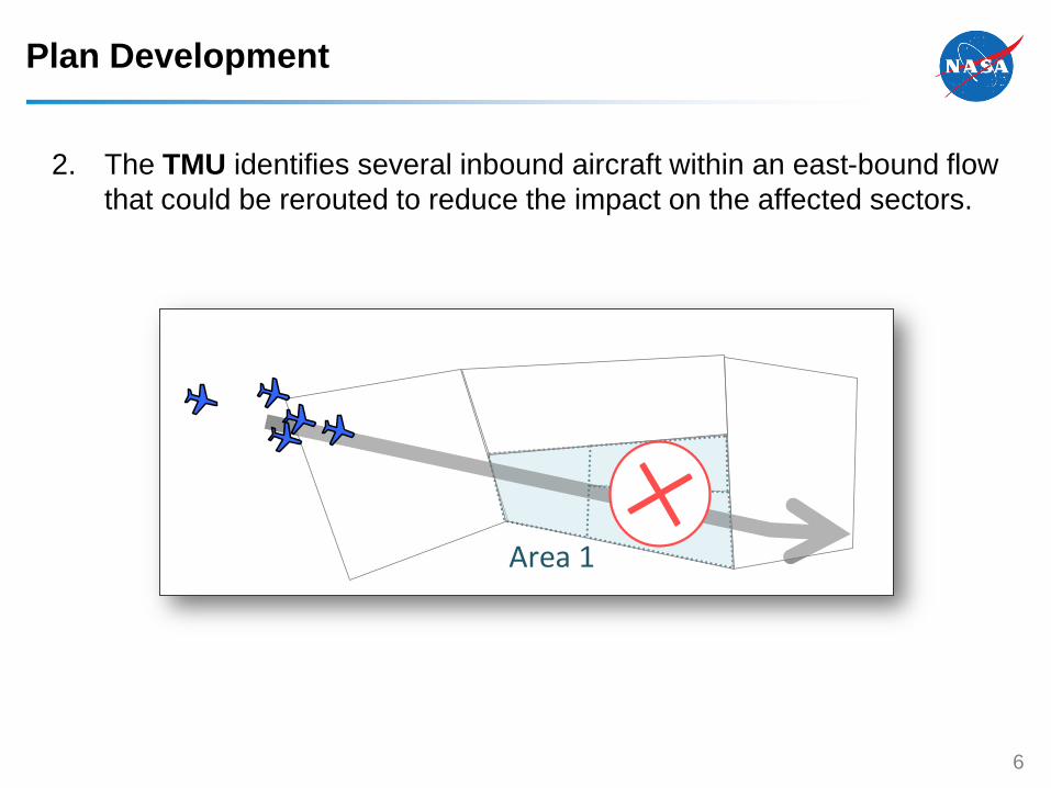
Plan Development
2. The TMU identifies several inbound aircraft within an east-bound flow
that could be rerouted to reduce the impact on the affected sectors.
6
Area 1

Plan Development and Coordination
3. The aircraft would be rerouted through Area 2. TMU confirms with
Area 2 supervisor that this is acceptable. TMU may also check with
Area 4.
7
Area 4
MSP
2
Area 2

Plan Coordination
4. TMU then confirms with the Area 3 supervisor that the Area 3
controllers can execute plan.
8
Area 3

Plan Execution
5. TMU prepares and sends 3 trajectory clearance requests to Sector A.
The controller reviews each request and issues it to the aircraft if
able.
9
A
Area 3

Execution and Follow-through
6. The Area 1 team manages the reduced flow through the two problem
sectors. TMU monitors solution effectiveness.
10
Area 1

Multi-Sector Planning: a Distributed Process
Or, an integrated process performed by a distributed team:
– Area supervisor and traffic management monitor local traffic situation.
– TMU plans trajectory changes, coordinating with supervisors and others.
– Area supervisors support plan development, and manage execution by controllers.
– TMU prepares and sends trajectory clearance requests to controllers.
– Controllers review trajectory requests and execute if suitable.
11
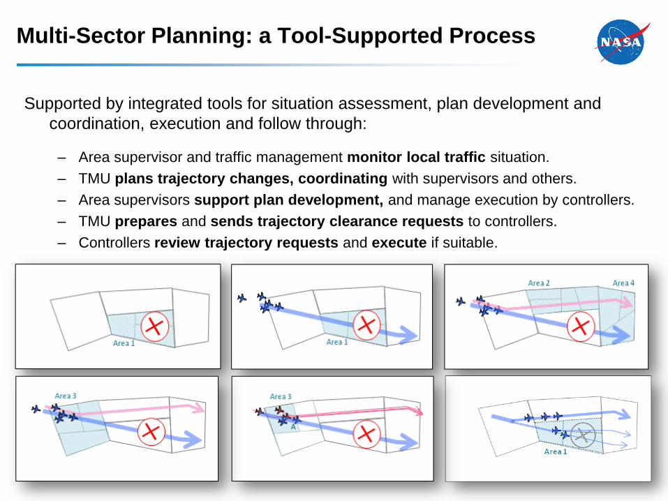
Multi-Sector Planning: a Tool-Supported Process
Supported by integrated tools for situation assessment, plan development and
coordination, execution and follow through:
– Area supervisor and traffic management monitor local traffic situation.
– TMU plans trajectory changes, coordinating with supervisors and others.
– Area supervisors support plan development, and manage execution by controllers.
– TMU prepares and sends trajectory clearance requests to controllers.
– Controllers review trajectory requests and execute if suitable.

Planner Automation Tools
13
Planning Station
Integrated tools support
situation assessment (load
tables, load graphs, traffic
display with weather and
filters), multi-trajectory trial
planning, and ground-to-
ground coordination of
plans and clearance
requests.
Station can be configured
for either TMU or area
operations.

Controller Automation Tools
14
Controller Station
Integrated tools support
development and exchange
of ground-to-ground
clearance requests, request
evaluation, and delivery of
requested clearance.
Equivalent capabilities are
provided to radar controller
and radar associate.

Flow-Based Trajectory Management in Mixed Equipage Airspace
• Why?
– Changing expectations for NextGen mid-term operational environment
• Motivation:
– Is full air-ground Data Comm environment necessary for these operations?
Or can they be introduced before full equipage (Data Comm) airspace exists?
• Answer two key questions:
– Could FBTM functions be feasible in this environment?
– Might FBTM functions provide benefit in this environment?
• Technical challenge:
– How to support FBTM in mixed equipage airspace?
15

Mixed Equipage Simulation
• Approach:
– Conduct a simulation to evaluate mixed equipage operations
– Leverage prior multi-sector planner research and simulations
– Adapt tools and concept for unequipped aircraft (non-Data Comm)
• Mixed equipage changes to FBTM tools and procedures:
– Functionality:
• Trajectories clearances that can be delivered by voice
• Complexity metric includes equipage weighting
– Display: Data block symbols and color coding denote equipage category
– Team Composition: Radar associate present on each sector
– Policy: Simulation provides a chance to explore “best-equipped, best-
served” approach for flow and trajectory management.
16

• Unequipped and equipped aircraft will travel through problem sectors.
• Planner re-routes unequipped aircraft first using named waypoints.
• Equipped aircraft can be re-routed later if necessary.
• Controllers were also asked to favor equipped aircraft in mixed equipage
conflicts.
Flow-Based Trajectory Management with Mixed Equipage
ABC
DEF
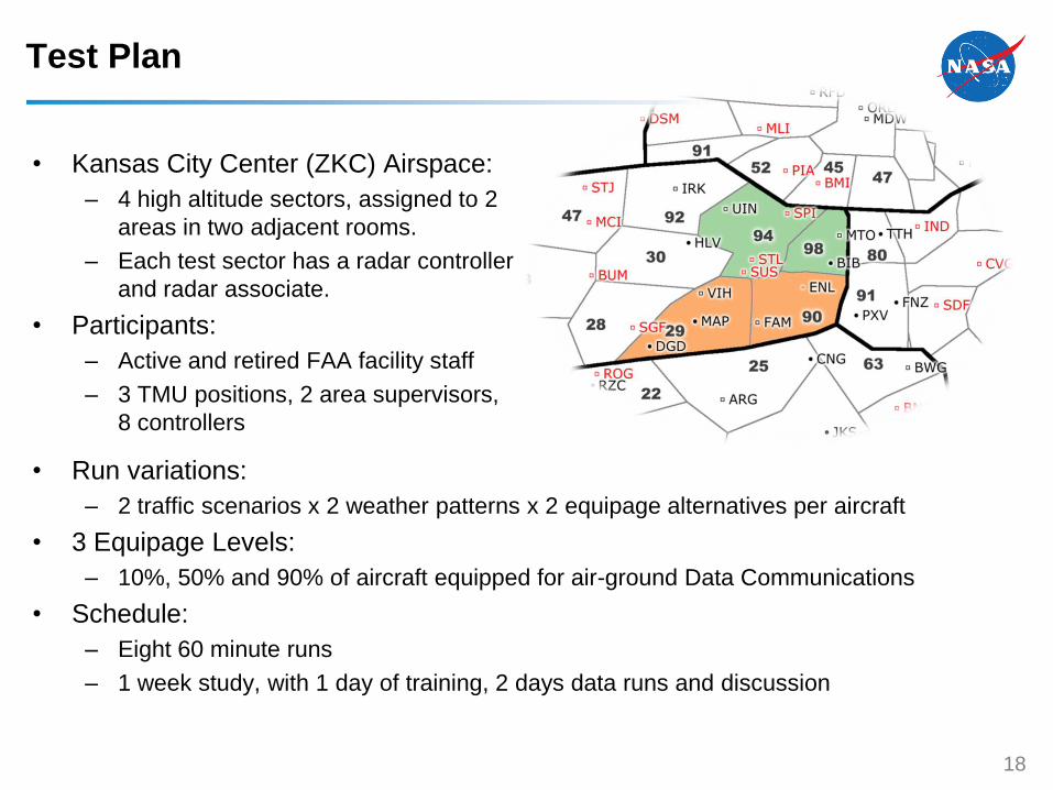
Test Plan
• Kansas City Center (ZKC) Airspace:
– 4 high altitude sectors, assigned to 2
areas in two adjacent rooms.
– Each test sector has a radar controller
and radar associate.
• Participants:
– Active and retired FAA facility staff
– 3 TMU positions, 2 area supervisors,
8 controllers
18
• Run variations:
– 2 traffic scenarios x 2 weather patterns x 2 equipage alternatives per aircraft
• 3 Equipage Levels:
– 10%, 50% and 90% of aircraft equipped for air-ground Data Communications
• Schedule:
– Eight 60 minute runs
– 1 week study, with 1 day of training, 2 days data runs and discussion

Scenario
• Convective weather affects local
facility and downstream facility
traffic.
• Supervisory traffic management
coordinator (STMC) discusses
situation with Command Center,
then supervisors.
• TMCs develop reroute plan to
manage airspace complexity.
19
• Unequipped aircraft add more to sector complexity (controller workload), so
TMCs reroute the unequipped aircraft first, which also provides benefit to the
equipped aircraft.

Results: System Performance with FBTM
• Planning operations maintained workload within limits at all 3 equipage levels.
• Higher equipage levels resulted in lower workload with higher throughput.
20
Mean number of aircraft through
sector per run, by equipage level
Mean workload rating, by
position and equipage level

Results: Service for Equipage at Local Area Level
• FBTM planning operations support “best-equipped best-served” policy across
equipage levels.
21
Total number of aircraft through
ZKC test sectors, by equipage,
across all 8 runs
Mean path length change per aircraft,
by equipage level, for aircraft flying
through the test area
0
1
2
3
4
5
6
10% Equipped 50% Equipped 90% EquippedCh
ange
in P
ath
Le
ngt
h (
nm
)Unequipped Equipped

Results: Service for Equipage at Sector Level
• Controllers provided priority service in conflict resolution across equipage levels.
22
Mean number of aircraft of each type
maneuvered to resolve mixed equipage
conflicts per run, by equipage level

Results: Tool Performance
• Tools were effective and satisfactory for mixed equipage operations.
• TMCs and controllers developed most of their clearance requests for unequipped aircraft.
• Only 10 out of 229 CCs sent to test sectors were rejected.
• TMCs gave both clearance coordination and trial planning functions for both equipage
types usability and usefulness ratings of 5.5 to 6, on a 1-6 scale.
23
Sender Uneq. Eq. Total
All positions
(TMC, supervisor or controller)1026 569 1595
Controllers from
participant-staffed sectors only 89 18 107
Number of Ground-to-Ground Clearance Requests,
by Sender and Equipage Type

Results: Some Participant Feedback
• Post-run and post-simulation data show mixed equipage concept to be
acceptable, with tools for trajectory coordination effectively used by all positions.
Some comments:
• Supervisors:
– Thought complexity management strategy was a “win-win” solution since moving an
unequipped aircraft out of a sector has greater impact, and also rewards equipped
aircraft with better service.
• TMCs:
– Wanted the FBTM tools integrated with current capabilities (traffic situation display) to
they could see how they would work together to make the “ideal TMU tool set.”
• Controllers:
– Priority handling of equipped aircraft was easy; prioritized resolution advisories would
have made it even more practical.
– Data Comm reduced workload, increasing safety and ability to handle more aircraft.

Conclusions
• FBTM operations are feasible and show benefit with mixed equipage.
• Trajectory clearances can be used with non-Data Comm aircraft.
• “Best-equipped, best-served” policy appears promising
Next Steps:
• NASA AOL continuing development of integrated NextGen operational
concepts, with “FBTM” functions as one component of our concept prototyping
environment.
25