a. nadji - cernaccelconf.web.cern.ch/accelconf/ipac10/talks/weoara02_talk.pdfa. nadji, ipac10,...
TRANSCRIPT

1
Progress Report
of
SESAME Project
A. NADJI
A. Nadji, IPAC10, Kyoto, 23 – 28 May 2010
On Behalf of SESAME Team

SESAME (Synchrotron-light for Experimental
Science and Applications in the Middle East)
is the first international 3rd generation synchrotron light source
in the Middle East region,
under construction near Amman (Jordan)
A. Nadji, IPAC10, Kyoto, 23 – 28 May 2010 2
What is SESAME?

Members:
Bahrain, Cyprus, Egypt, Israel,
Iran, Jordan, Pakistan,
Palestinian Authority, Turkey.
Pending (?): Iraq
Observers: France, Greece,
Germany, Italy, Japan, Kuwait,
Portugal, Russian Federation,
Sweden, UK and USA
A. Nadji, IPAC10, Kyoto, 23 – 28 May 2010 3
Purpose: Foster excellent science and technology in the Middle
East (and prevent or reverse the brain drain).
+ Build bridges between diverse societies, and contribute to a
culture of peace through international collaboration in science.

Very Brief History of SESAME
1997: proposal by Prof Herman Winick (SLAC) and Prof G.-A. Voss
(DESY):
rebuild old 0.8 GeV BESSY I in the Middle East, as basis for a new
international organization, modeled on CERN, under umbrella of
UNESCO.
2002: Shipment of BESSY I to Jordan
2002: decision to build a new 2.5 GeV ring (BESSY I as injector)
world competitive device
2003: Ground breaking Ceremony
foundation of SESAME
A. Nadji, IPAC10, Kyoto, 23 – 28 May 2010 4
2008: Completion of the building

SESAME GROUND BREAKING CEREMONY - 6 JANUARY 2003
A. Nadji, IPAC10, Kyoto, 23 – 28 May 2010 5

SESAME building, financed by Jordan
Opening of the SESAME building
3 November 2008
A. Nadji, IPAC10, Kyoto, 23 – 28 May 2010 6

#4
#5
#6
#7
#8
#9
#10
#11 #12
#13
#14
#15
#16
#2
#3
#1
Main Ring Parameters:
Energy = 2.5 GeV
Circumference = 133.2 m
Emitt. = 26.0 nm.rad
16 Straights sections
8 x 4.44 m + 8 x 2.38 m
Up to 28 Beamlines:
12 Insertion Devices
16 Dipole ports withBessy I
800 MeV
Booster
2.5 GeV Main Storage Ring
SESAME ACCELERATOR COMPLEX
Injector
RF
Injection
straights
00
6.50
Beamlines
length range from
21 m – 36.7 m
SESAME FACILITY
7

Status of the MICROTRON
8A. Nadji, IPAC10, Kyoto, 23 – 28 May 2010

MICROTRON Subsystems Tests in the Hanger
A. Nadji, IPAC10, Kyoto, 23 – 28 May 2010 9
(April – June 2008)

MICROTRON Installation in the
SESAME Experimental Hall25/08/2008
A. Nadji, IPAC10, Kyoto, 23 – 28 May 2010 10

11
The MICROTRON System installed and tested
at BESSY (1998) at SESAME (end 2008)
A. Nadji, IPAC10, Kyoto, 23 – 28 May 2010

Temporary Shielding for MICROTRON Operation
A. Nadji, IPAC10, Kyoto, 23 – 28 May 2010 12

JULY, 14th
, 2009 (00:35)
A. Nadji, IPAC10, Kyoto, 23 – 28 May 2010 13
FIRST SESAME MICROTRON BEAM

Status of the BOOSTER
14A. Nadji, IPAC10, Kyoto, 23 – 28 May 2010

Tests of Booster Equipment
Injection Septum
Extraction Kicker
Injection Kicker
Extraction Septum
RF Cavity
Magnets
A. Nadji, IPAC10, Kyoto, 23 – 28 May 2010 15

Booster’s Magnets Hydraulic tests
Water Magnet CleaningHydraulic Cell Assembly
Flow Switch Test
16A. Nadji, IPAC10, Kyoto, 23 – 28 May 2010
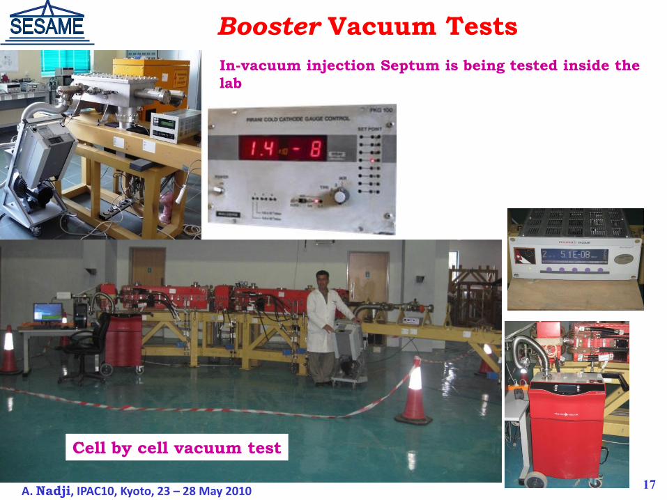
Booster Vacuum Tests
17
In-vacuum injection Septum is being tested inside the
lab
A. Nadji, IPAC10, Kyoto, 23 – 28 May 2010
Cell by cell vacuum test

The whole Booster’s Vacuum Tests
18A. Nadji, IPAC10, Kyoto, 23 – 28 May 2010

Brazing by DIN 8513 LAG40 CD
Holes of 1 to 3 cm in length were discovered in two dipole chambers. Up to
now, the reason is unknown.
Welding using silver, under Argon shield, gave a good result.
No visible hole in all the other chambers (helium leak detector). Nevertheless,
it is essential to understand the reason of the presence of these holes before the
installation of the Booster. Inspection is underway.
A worry!
A. Nadji, IPAC10, Kyoto, 23 – 28 May 2010 19

20
Booster’s pulsed Injection and Extraction system tests
Successfully tested
A. Nadji, IPAC10, Kyoto, 23 – 28 May 2010

21
Booster’s pulsed Injection and Extraction system tests
Injection kicker tests results
220 A
4 us
A. Nadji, IPAC10, Kyoto, 23 – 28 May 2010

Booster RF System
The Booster RF system is complete and ready to be installed in the Booster
tunnel.
All the subsystems have been tested and connected, including Cavity, LLRF,
solid-state transmitter, interlocks and RF control system.
Booster RF system Booster RF Cavity during commissioning
A. Nadji, IPAC10, Kyoto, 23 – 28 May 2010 22

Booster Beam Diagnostics Tests Preparation
BPM sets Response initial tests assembly (Down left), and High frequencytermination/50Ω preparation (Down right) at the electric Lab.
BPM sets
23A. Nadji, IPAC10, Kyoto, 23 – 28 May 2010

Booster Dipole Magnet Power Supply
Under manufacture at Bruker (France)
24A. Nadji, IPAC10, Kyoto, 23 – 28 May 2010

Booster Quadrupoles Power SuppliesUnder manufacture at Bruker (France)
25

Status of the
STORAGE RING
26A. Nadji, IPAC10, Kyoto, 23 – 28 May 2010

STORAGE RING OPTICS
27A. Nadji, IPAC10, Kyoto, 23 – 28 May 2010

1E+12
1E+13
1E+14
1E+15
1E+16
0.1 1 10 100Photonenergy (KeV)
Phot
ons
/ sec
/ 0.
1% B
WIn-Vacuum (6mm gap) Undulator, 25mm
Wiggler, 3.5T, 60mm
Wiggler, 2.5T, 120mm
Undulator, 40mm
Bending, 2.5GeV
FLUX
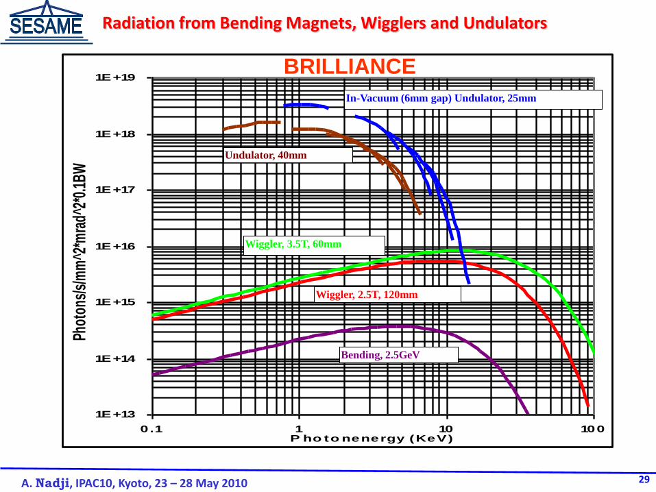
Radiation from Bending Magnets, Wigglers and Undulators
28A. Nadji, IPAC10, Kyoto, 23 – 28 May 2010
1E+13
1E+14
1E+15
1E+16
1E+17
1E+18
1E+19
0.1 1 10 100P ho to nenergy (KeV)
Phot
ons/
s/m
m^2
*mra
d^2*
0.1B
W
Undulator, 40mm
Wiggler, 3.5T, 60mm
Wiggler, 2.5T, 120mm
Bending, 2.5GeV
In-Vacuum (6mm gap) Undulator, 25mm
BRILLIANCE
Radiation from Bending Magnets, Wigglers and Undulators
29A. Nadji, IPAC10, Kyoto, 23 – 28 May 2010

Magnetic Design Complete
1.62 T
1.58 T
1.57 T
-0.4
-0.35
-0.3
-0.25
-0.2
-0.15
-0.1
-0.05
0
-25 -15 -5 5 15 25
Leff(x
) -
Leff(x
=0
) [m
m]
Transverse Position [mm]
End-chamfer to achieve the same effective
magnetic length along the transversal position.
30
Example of the
Bending Magnet
A. Nadji, IPAC10, Kyoto, 23 – 28 May 2010

31
3D Mechanical Engineering Design
Sextupole
A. Nadji, IPAC10, Kyoto, 23 – 28 May 2010

A. Nadji, IPAC10, Kyoto, 23 – 28 May 2010
Arc vacuum chamber
Crotch absorber
32

Microtron and its racks
33
RADIATION SCHIELDING WALL CONSTRUCTION

34

35

36

A Proposal for the Installation of the
Solid State Amplifiers of the Storage Ring RF System
37A. Nadji, IPAC10, Kyoto, 23 – 28 May 2010
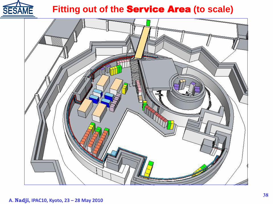
38
Fitting out of the Service Area (to scale)
A. Nadji, IPAC10, Kyoto, 23 – 28 May 2010

Survey & Alignment Network
39A. Nadji, IPAC10, Kyoto, 23 – 28 May 2010

No. Beamline Energy Range Source Type Donation
1. Protein Crystallography 4 – 14 keV Wiggler (ALS) Daresbury
DL – 14.1 & 14.2
2. XAFS/XRF 3 – 30 keV Bending Magnet Daresbury
DL – 4.1 & 4.2
3. Infra-red Spectro-microscopy 0.01 – 1 eV Bending Magnet -
4. Soft X-ray, Vacuum Ultra
Violet (VUV)
0.05 – 2 keV Elliptically Polarizing
Undulator
-
5. Small and Wide Angle X-ray
Scattering
(SAXS/WAXS)
8 – 12 keV Bending Magnet Daresbury
DL – 16.1
6. Powder Diffraction 3 – 25 keV Multi-pole Wiggler SLS
7. Extreme Ultraviolet (EUV) 10 – 200 eV Bending Magnet LURE
PHASE 1 BEAMLINES
40A. Nadji, IPAC10, Kyoto, 23 – 28 May 2010

I07
(Protein Cristallograhy)
D09
(XAFS/XRF)
D03 (IR)
I08 D10
I11
D12
Location of PHASE 1 Beamlines
41A. Nadji, IPAC10, Kyoto, 23 – 28 May 2010

42
Major tasks for the Storage Ring until the start of the commissioning
Storage
Ring
2009 2010 2011 2012 2013 2014
3 6 9 12 3 6 9 12 3 6 9 12 3 6 9 12 3 6 9 12 3 6 9 12
Magnets Vacuum Syst. Girders Alignment Power Supplies Diagnostics RF system Pulsed
Magnets
Puls. Pow. Suppl. Timing System Control System Shielding PSS Cooling
System
Radiation Monitors Insertion Devices Front Ends Commissioning
with Beam
A. Nadji, IPAC10, Kyoto, 23 – 28 May 2010

Item Budget
Without
options
Budget With
options
Microtron + Booster +
Storage Ring (M€) 15.340 17.940
Infrastructure (M€) 3.160 3.160
Contingency (10%) (M€)
1.850 2.110
Total in M€ 20.350 23.210
Total in MUS$ 30.525 34.815
43
Cost of Completing Construction
A. Nadji, IPAC10, Kyoto, 23 – 28 May 2010

44
Name Field of Activity Nat. Hir. Date
1 Maher Attal Acc. Physics. Palestine Jan 2004
2 Firas Makahleh Cooling and Vacuum Jordan Jun 2004
3 Seadat Varnasseri Diagnostics & Puls. Magnets &
Power Supplies
Iran Jul 2004
4 Adel Amro Vacuum & Service Area Jordan Jul 2004
5 Maher Shehab Mech. Engineering Jordan Feb 2005
6 Darweesh Foudeh RF & Electronics Jordan June 2007
7 Arash Kaftoosian RF Iran Oct 2005
8 Hamed Tarawneh Acc. Physics/ Magnet Jordan Mar. 2006
9 Moh’d. Alnajdawi Mechanical Engineering Jordan June 2007
10 Salman Matalgah Computing and Network Jordan Sept. 2007
11 Ahed Aladwan Control System Jordan March 2007
12 Adli Hamad Radiation Safety Jordan June 2007
13 Thaer Abu Haniah Alignment & Survey Jordan Nov. 2007
14 Tasadaq Ali Khan RF & Control Pakistan Nov. 2007
15 Saed Budair Vacuum Jordan July 2008
16 Muayed Sbahi Electrical & Cabling Jordan August 2008
SESAME Technical Staff
A. Nadji, IPAC10, Kyoto, 23 – 28 May 2010
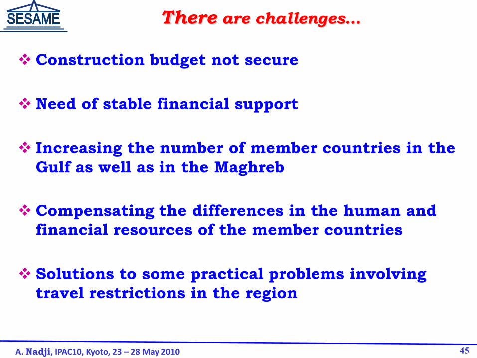
Construction budget not secure
Need of stable financial support
Increasing the number of member countries in the
Gulf as well as in the Maghreb
Compensating the differences in the human and
financial resources of the member countries
Solutions to some practical problems involving
travel restrictions in the region
There are challenges…
A. Nadji, IPAC10, Kyoto, 23 – 28 May 2010 45

1.2 M€ from EU – Jordan
Electronic, RF, Control and Vacuum labs
Mechanical workshop
Refurbishment of the Microtron
500 kJD from Ministry Of Higher Education- Jordan
Network infrastructure
3.1M US$ from Jordan Royal Court
Alignment tools and network
Radiation shielding wall construction
Complement for the network
Bridge and cable trays
Construction Funds (spent)
46

Training Programme
One of the essential objectives of SESAME
Funded by IAEA, other organisations around the world, and
numerous synchrotron laboratories which provide training
opportunities : ALBA, ESRF, PF, SLS, SOLEIL,…
Many workshops, users’ meetings: + schools supported byJSPS
Travel support from APS-EPS-IoP-DPG, ICTP and Canon Foundation (UK)
A. Nadji, IPAC10, Kyoto, 23 – 28 May 2010 47

Strong and Continuous help and advice
from SOLEIL.
Signature of the Collaboration between
SESAME and SOLEIL (France) (October 23, 2007)
A. Nadji, IPAC10, Kyoto, 23 – 28 May 2010 48

CONCLUSION
A. Nadji, IPAC10, Kyoto, 23 – 28 May 2010 49
The shielding wall is under construction.
The Microtron has been successfully commissioned with beam
at low energy.
All the existing Booster subsystems have been tested and new Booster
magnets power supplies are being manufactured. More investigation are
made for the vacuum chambers.
The design of the Storage Ring equipment is finalised and technical
specifications are ready for call for tender.
We have come this far, we have to believe we will get there
We will keep the faith but we need your help.