a new uwb small dimension mtm antennas based on...
TRANSCRIPT
HCTL Open Int. J. of Technology Innovations and ResearchHCTL Open IJTIR, Volume 2, March 2013e-ISSN: 2321-1814ISBN (Print): 978-1-62776-111-6
A New UWB SmallDimension MTMAntennas Based on CRLHTransmission Lines forModern WirelessCommunication Systemsand Portable DevicesMohammad Alibakhshi-Kenari∗[email protected]
Abstract
In this report, novel ultra wideband (UWB) small antennas basedon the composite right/left-handed transmission lines structuresare proposed and designed. The antennas are presented with
best in size, bandwidth and radiation patterns. The physical sizeand the operational frequency of the antennas depend on the unitcell size and the equivalent transmission line model parameters ofthe CRLH-TL. To realize characteristics of first proposed antenna,
∗Department of Electrical Engineering at Shahid Bahonar University of Kerman, Kerman,Iran
Mohammad Alibakhshi-KenariA New UWB Small Dimension MTM Antennas Based on CRLH TransmissionLines for Modern Wireless Communication Systems and Portable Devices.
Page 25

HCTL Open Int. J. of Technology Innovations and ResearchHCTL Open IJTIR, Volume 2, March 2013e-ISSN: 2321-1814ISBN (Print): 978-1-62776-111-6
Q-shaped gaps printed into rectangular radiation patches are used.The CRLH antenna is composed of two unit cells, each of whichoccupies only 10.8 mm x 8.6 mm. This antenna can be covers thebandwidth from 2.7 - 9.3 GHz for VSWR < 2. The antenna peak gainand radiation efficiency, respectively, are 5.78 dBi and 42.1% whichhappens at f = 9.3 GHz. Moreover, second antenna with same insize and enhancement bandwidth, gain and radiation efficiency thanthe first proposed antenna with similar design procedure is designed.This antenna is constructed of the printed Q-shaped four unit cells.The length, width and height of the later antenna are 21.6 mm,8.6 mm and 1.6 mm, respectively, and this antenna can be coversbandwidth from 4.1 - 11.7 GHz for VSWR < 2, and also highestgain and radiation efficiency are 7.18 dBi and 92.69%, respectivelyat f = 4.1 GHz.
Keywords
Printed Q-shaped antennas, Ultra Wide Band (UWB) Antennas, Small Anten-nas, Composite Right/Left-handed Transmission lines (CRLH-TLs), Metamate-rial (MTM), Modern Wireless Communication Systems, Portable Devices.
Introduction
Since their invention back in 1960s, microstrip patch antennas have foundnumerous applications for their simplicity in fabrication, compatibility withplanar circuitry, low profile and planar structures, and unidirectional radiationcapability. Despite many nice electrical and mechanical features of microstripantennas, their use for a number of applications at low microwave frequencieshas been limited due to their limited size and bandwidth.
The conventional approach for miniaturizing the antenna size is to print theradiator on a high dielectric substrate. However, because of the capacitivenature of the patch geometry and the existence of strong impedance contrastbetween the antenna substrate and the free space surrounding region, a largeamount of electric energy is trapped inside the dielectric material resulting in anarrow antenna bandwidth and radiation loss. The metamaterials (MTMs) arevery attractive for the design of small antennas and microwave devices [1, 2].The composite right/left handed transmission lines (CRLH-TLs) provides aconceptual route for implementing small antennas. CRLH-based antennas canalso be made very broadband to support today’s multi band communication
Mohammad Alibakhshi-KenariA New UWB Small Dimension MTM Antennas Based on CRLH TransmissionLines for Modern Wireless Communication Systems and Portable Devices.
Page 26

HCTL Open Int. J. of Technology Innovations and ResearchHCTL Open IJTIR, Volume 2, March 2013e-ISSN: 2321-1814ISBN (Print): 978-1-62776-111-6
and wireless applications requirements. The commercial uses of frequency band3 GHz to 10.6 GHz for radar, location tracing, and data transmissions wereapproved by FCC in 2002 [3]. Recently, the Research and development of theUWB systems including antennas have been widely performed [4, 5, 6]. One ofthe main devices of the UWB system is an antenna. The low VSWR (VSWR< 2) over 3 - 10.6 GHz band is required. Two CRLH-based antennas designedin here, can supports all cellular frequency bands (from 2.7 GHz to 11.7 GHz),using single or multiple feed designs, which eliminates the need for antennaswitches. Significant size reduction is also demanded to achieve the minimizationof communication systems or devices. Ideally, the UWB antenna should besmall, low cost, planar, and reliable. Compatibility and ease of integration withelectronics for mobile communications also desirable. Furthermore, in orderto satisfy the various demands for communication and wireless services, smallantenna with wide bandwidth and good radiation characteristics are needed.We in report design two antennas based on CRLH-TLs which consist of smallarea, planar, low cost, ease in fabrication, very wideband and good radiationproperties, therefore these antennas may be good candidate for modern com-munication systems.
Developments of wireless communications systems call for more compact andmulti frequency antennas. In particular, next generation wireless devices willrequire multiple antennas to coexist in a small area, while maintaining their lowcoupling to support multipath channel decorrelation. Metamaterial structureshave the ability to concentrate electromagnetic fields and currents near an-tenna structures, instead of spreading them along the antenna ground, causinghigher coupling between antennas. This allows compact antenna arrays to berealized with minimal mutual coupling, to be able to decorrelate multipathchannels in MIMO implementations [7, 8]. In this paper, we will focus ontransmission lines (TL) based on composite right- and lefthand (CRLH) propa-gation [9]-[24]. It is nearly impossible to implement a pure left-handed (LH)transmission line due to the right-handed (RH) propagation inherited by usinglumped elements [9]. Such transmission lines make possible unprecedentedimprovements in air-interface integration, over the air (OTA) performance andminiaturization, while simultaneously reducing bill-of-materials (BOM) costsand specific absorption rate (SAR) values. Metamaterials enable physicallysmall but electrically large air-interface components, with minimal couplingamong closely spaced devices.
Metamaterials (MTM) are man-made composite materials, engineered to pro-duce desired electromagnetic propagation behaviour not found in natural me-
Mohammad Alibakhshi-KenariA New UWB Small Dimension MTM Antennas Based on CRLH TransmissionLines for Modern Wireless Communication Systems and Portable Devices.
Page 27
HCTL Open Int. J. of Technology Innovations and ResearchHCTL Open IJTIR, Volume 2, March 2013e-ISSN: 2321-1814ISBN (Print): 978-1-62776-111-6
dia [9, 10]. The word metamaterial refers to many variations of these man-made structures. Metamaterial antenna structures are copper, printed directlyon the dielectric substrate, and can be fabricated by using a conventionalRogers RT Duroid5880 substrate or a flexible printed circuit (FPC) board.Recently, novel antennas with these characteristics have been designed byusing composite right/left-handed transmission line (CRLH-TL) metamate-rials [11, 12]. Unlike traditional right-handed (RH) transmission materials,metamaterials based on left-handed (LH) transmission lines (TLs) have uniquefeatures of anti parallel phase and group velocities (vp − ||vg) [11]-[13]. PureLH TLs cannot be implemented due to the existence of RH parasitic effectsthat occur naturally in practical LH TLs. CRLH-TL structures have beenproposed, which also include RH effects. Several metamaterials-based antennashave already been presented, such as backward-to-forward leaky-wave anten-nas [14]-[15], zeroth-order resonant antennas [16], and so on.
Metamaterials are broadly defined as effectively homogeneous artificial struc-tures exhibiting unusual properties, such as, for instance, an index of refractionthat may be negative (left handedness), less than one, or modulated in a gradedmanner. Such materials have spurred considerable interest and led to numerousapplications over the past decade [18, 19].
Metamnaterials may be equivalently described in terms of media parameters(electric/magnetic dipole moments, electric/ magnetic susceptibilities, permit-tivity, permeability), or in terms of transmission-line (TL) parameters (induc-tance/capacitance, impedance/ admittance, propagation constant/characteristicimpedance). The latter approach, introduced in [20, 21], has led to low-loss andbroadband metamnaterials, due to the non-resonant nature of the structuralelements. This has been the foundation for the vast majority of the practicalapplications reported to date. More particularly, the concept of compositeright/left-handed (CRLH) transmission-line metamnaterials (introduced in [22]and theorized in [23]), which describes in a simple and insightful manner thefundamentally dual right-handed (RH)/left-handed (LH) nature of metamateri-als, has been widely recognized as a powerful paradigm for the understandingof metamaterial phenomena and the design of metamaterial devices.
The applications of metamaterials may be classified in three categories:
1. Guided-wave components (multi band, enhanced bandwidth, and miniatur-ized components; tight broadband couplers; compact resonators; uniformpower combiners and splitters; UWB filters; agile distributed amplifiers;
Mohammad Alibakhshi-KenariA New UWB Small Dimension MTM Antennas Based on CRLH TransmissionLines for Modern Wireless Communication Systems and Portable Devices.
Page 28

HCTL Open Int. J. of Technology Innovations and ResearchHCTL Open IJTIR, Volume 2, March 2013e-ISSN: 2321-1814ISBN (Print): 978-1-62776-111-6
impulse delay lines and circuits);
2. Refracted-wave systems (focusing slabs, super-resolution imagers, reflection-less curved refractors, coordinate-transformation-based graded-index struc-tures for electromagnetic manipulations); and
3. Radiated-wave devices (mono/multi band passive/active one dimensional/twodimensional printed planar antennas and reflectors).
This report is concerned with the third category. It presents a selected numberof the most practical CRLH metamaterial printed planar antennas. Design andfabrication of these antennas is based on utilizing composite right/left-handed(CRLH) metamaterial (MTM) transmission lines (TLs) technology and printedplanar methodology which caused to gap capacitance that act like series capac-itance and this methodology with MTM technology using for foot print areareduction, also employing appropriate inductive elements, such as rectangularinductors and metallic via holes with their optimize structural values thatprovides shunt inductance accompanying suitable tuning distance between gapedges and using low loss materials for enhancement bandwidth and maximizesradiation characteristics. Design procedures of the antennas based on the abovemethods are discussed in the following sections.
This paper is organized as follows. Section 2 introduced antenna based oncomposite right/left-handed metamaterial transmission lines. This section, firstestablishes the fundamental of CRLH metamaterial transmission line structures(Section 2 A). It then presents CRLH Metamaterial technology in antennadesign (Section 2 B). Next section recommends a new idea of the design UWBsmall CRLH MTM antennas as section 3 first proposed UWB and compactCRLH MTM printed two unit cells antenna (Section 3 A). It then presentsimprovement gain antenna with printed Q-shaped four unit cells structure(Section 3 B). In following simulation results and discussions of the proposedprinted antennas arrangements in section 4. Afterwards in section 5, we haveprovided a brief talk about benefits of the presented CRLH based antennas.Finally, discussion and conclusion are raised.
Antennas based on Composite Right/Left-HandedMetamaterial Transmission Lines
Mohammad Alibakhshi-KenariA New UWB Small Dimension MTM Antennas Based on CRLH TransmissionLines for Modern Wireless Communication Systems and Portable Devices.
Page 29

HCTL Open Int. J. of Technology Innovations and ResearchHCTL Open IJTIR, Volume 2, March 2013e-ISSN: 2321-1814ISBN (Print): 978-1-62776-111-6
Fundamentals of CRLH Metamaterial Transmission LineStructures
Figure 1 shows the equivalent circuit of periodic CRLH metamnaterial trans-mission lines (MTM TLs) in general case (lossy case). It should be noted thatperiodicity is here a convenience but not a necessity, as long as the largestcell is much smaller than the guided wavelength (p<< λg) for electromagnetichomogeneity. Another important note is that as long as the effective mediumcondition, p<< λg is satisfied, there is no constraint on the minimum numberof unit cells required for metamaterial operation. Even one single cell, whenperfectly matched to the external world (i.e., presenting a bloch impedanceequal to that of the external media or ports), behaves in a manner that cannotbe distinguished from the behavior of a perfectly continuous medium of thesame electrical size for the wave crossing it.
The homogeneous models of a purely RH, purely LH, and CRLH lossless
Figure 1: The equivalent circuit model of periodic homogeneous CRLH metamnaterialtransmission lines structures composed of N unit cells in general case (lossycase)
transmission lines are shown in figure 2 (A),(B) and (C) respectively [11]. Fora purely RH lossless TL, its model is developed from conventional infinitesimalcircuit model, where LR is a series inductance and CR is a shunt capacitance.The purely LH model is obtained by interchanging the inductance/capacitanceand inverting the series/parallel arrangements in the equivalent circuit of theRH-TL, where CL presents a series capacitance and LL presents a shunt in-ductance. In effect, parasitic capacitance CR due to development of voltagegradients and unavoidable parasitic inductance LR due to current flow alongthe metallization will be added to LH TL and result in CRLH TL structure [11].
The quantities such as resistance R of the conductors, inductance L (due to
Mohammad Alibakhshi-KenariA New UWB Small Dimension MTM Antennas Based on CRLH TransmissionLines for Modern Wireless Communication Systems and Portable Devices.
Page 30

HCTL Open Int. J. of Technology Innovations and ResearchHCTL Open IJTIR, Volume 2, March 2013e-ISSN: 2321-1814ISBN (Print): 978-1-62776-111-6
Figure 2: Equivalent circuit models: (A) Homogeneous RH TL, (B) Homogeneous LHTL, (C) Homogeneous CRLH TL [11]
the magnetic field around the patches, self inductance, etc), capacitance C andconductance G of the dielectric material separating the two conductors areknown as the primary line constants, from which the secondary line constants,these being the propagation constant, attenuation constant and phase constantare derived. The propagation constant, symbol γ, for a given system is definedby the ratio of the amplitude at the source of the wave to the amplitude at somedistance x [28] expressed as:
A0
Ax= eγx (1)
Since the propagation constant, is a complex quantity we can write:
γ = α+ jβ (2)
where, α, the real part, is called the attenuation constant, β, the imaginarypart, is called the phase constant.
γ =√ZY (3)
For example in a copper transmission line, the propagation constant can becalculated from the primary line constants by means of the relationship: whereZ and Y are, respectively, the impedance and admittance of the transmissionline. In the special case of the CRLH TL, Z and Y are defined as [11]:
Z(ω) = j
(ωLR −
1
ωCL
)(4)
Mohammad Alibakhshi-KenariA New UWB Small Dimension MTM Antennas Based on CRLH TransmissionLines for Modern Wireless Communication Systems and Portable Devices.
Page 31
HCTL Open Int. J. of Technology Innovations and ResearchHCTL Open IJTIR, Volume 2, March 2013e-ISSN: 2321-1814ISBN (Print): 978-1-62776-111-6
Y (ω) = j
(ωCR −
1
ωLL
)(5)
After calculation, the dispersion relation for a homogeneous CRLH TL is [11]:
β(ω) = s(ω)
√ω2LRCR +
1
ω2LLCL−(LRLL
+CRCL
)(6)
where [11]
s(ω) =
−1 if ω < ωse = min(
1√LRCL
,1√LLCR
)
0 if ωse < ω < ωsh
+1 if ω > ωsh = max(1√LRCL
,1√LLCR
)
(7)
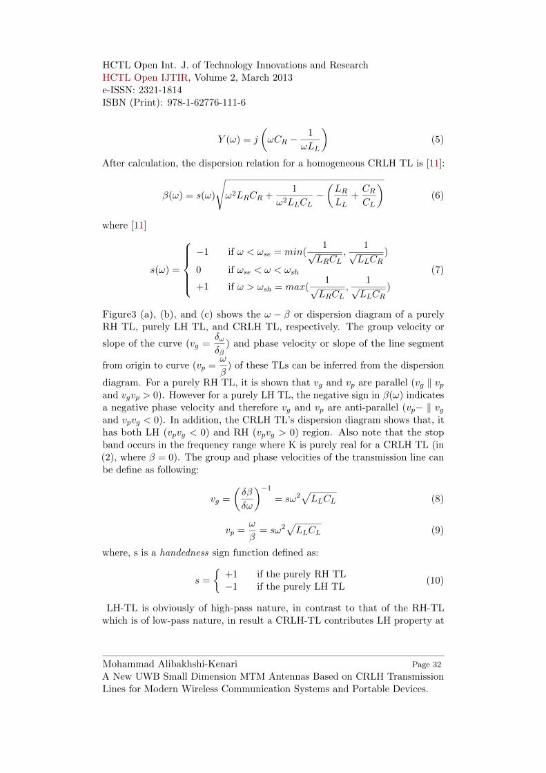
Figure3 (a), (b), and (c) shows the ω − β or dispersion diagram of a purelyRH TL, purely LH TL, and CRLH TL, respectively. The group velocity or
slope of the curve (vg =δωδβ
) and phase velocity or slope of the line segment
from origin to curve (vp =ω
β) of these TLs can be inferred from the dispersion
diagram. For a purely RH TL, it is shown that vg and vp are parallel (vg ‖ vpand vgvp > 0). However for a purely LH TL, the negative sign in β(ω) indicatesa negative phase velocity and therefore vg and vp are anti-parallel (vp− ‖ vgand vpvg < 0). In addition, the CRLH TL’s dispersion diagram shows that, ithas both LH (vpvg < 0) and RH (vpvg > 0) region. Also note that the stopband occurs in the frequency range where K is purely real for a CRLH TL (in(2), where β = 0). The group and phase velocities of the transmission line canbe define as following:
vg =
(δβ
δω
)−1
= sω2√LLCL (8)
vp =ω
β= sω2
√LLCL (9)
where, s is a handedness sign function defined as:
s =
+1 if the purely RH TL−1 if the purely LH TL
(10)
LH-TL is obviously of high-pass nature, in contrast to that of the RH-TLwhich is of low-pass nature, in result a CRLH-TL contributes LH property at
Mohammad Alibakhshi-KenariA New UWB Small Dimension MTM Antennas Based on CRLH TransmissionLines for Modern Wireless Communication Systems and Portable Devices.
Page 32

HCTL Open Int. J. of Technology Innovations and ResearchHCTL Open IJTIR, Volume 2, March 2013e-ISSN: 2321-1814ISBN (Print): 978-1-62776-111-6
Figure 3: Dispersion diagrams for the TLs of Figure 2. (a) Homogeneous RH TL, (b)Homogeneous LH TL, (c) Homogeneous CRLH TL (unbalanced case) [11].
lower frequencies and RH at higher frequencies with a transition frequency ω0.It has been developed that under balanced condition (11) or (12), when theseries and shunt resonances (ωse and ωsh) are equal [11],
ωse =1√LRCL
= ωsh =1√LLCR
(11)
orLRCL = LLCR (12)
in results the propagation constant in (6) reduces to the simpler expression [11]
β = βR + βL = ω√LRCR −
1
ω√LLCL
(13)
where the phase constant distinctly splits up into the RH phase constant βRand the LH phase constant βL. Thus, there is a seamless transition from LH toRH for the balanced case occurring at the transition frequency ω0[11]:
ωunbalanced0 =1
4√LRCRLLCL
(14)
and in the balanced case, ω0 balanced is equal:
ωbalanced0 =1√LRCL
=1
LLCR(15)
Mohammad Alibakhshi-KenariA New UWB Small Dimension MTM Antennas Based on CRLH TransmissionLines for Modern Wireless Communication Systems and Portable Devices.
Page 33

HCTL Open Int. J. of Technology Innovations and ResearchHCTL Open IJTIR, Volume 2, March 2013e-ISSN: 2321-1814ISBN (Print): 978-1-62776-111-6
A balanced form of a CRLH TL is shown in figure 4. The simplified equivalentcircuit model is the series combination of a RH and a LH TLs. Also, thebalanced CRLH TL’s dispersion curve does not have a stop band. In addition,at ω0 the phase shift (φ = −βd) for a TL of length d is zero (β = 0). Phaseadvance (φ > 0) occurs in the LH frequency range (ω < ω0, β < 0), and phasedelay (φ < 0) occurs in the RH frequency range (ω > ω0, β > 0)[11]. The
Figure 4: Balanced form of figure 2(c). (a) Simplified equivalent circuit model, (b)Dispersion diagram showing seamless transition from LH to RH region [11].
characteristic impedance of a TL is given by Z0 =
√Z
Y. For the CRLH TL, in
unbalanced case the characteristic impedance is [11]:
Z0 = ZL
√CLLRω
2 − 1
CRLLω2 − 1(16)
in the balanced case: Z0 = ZL = ZR, with,
ZL =
√LLCL
(17)
ZR =
√LRCR
(18)
where ZL and ZR are the purely LH and RH impedances, respectively. Accord-ing to (16) the characteristic impedance for the unbalanced case is frequencydependent, however, according to (17) and (18) for the balanced case is fre-quency independent and therefore, can be matched over a wide bandwidth.
Mohammad Alibakhshi-KenariA New UWB Small Dimension MTM Antennas Based on CRLH TransmissionLines for Modern Wireless Communication Systems and Portable Devices.
Page 34

HCTL Open Int. J. of Technology Innovations and ResearchHCTL Open IJTIR, Volume 2, March 2013e-ISSN: 2321-1814ISBN (Print): 978-1-62776-111-6
The permeability and permittivity of a TL material have been related tothe impedance and admittance of its equivalent TL model:
µ =Z
jω= LR −
1
ω2CL(19)
ε =Y
jω= CR −
1
ω2LL(20)
Equations (19) and (20) verified that for balanced case the permeability andpermittivity are negative in LH region, where ω < ω0.
The index of refraction (n =cβ
ω) for the balanced and unbalanced CRLH-
TL is displayed in figure 5 [11]. This figure 5 shows that the CRLH-TL has anegative index of refraction in its LH range and a positive index of refractionin its RH range.
Figure 5: Typical index of refraction plots for the balanced (green) and unbalanced(red) CRLH TL [11].
CRLH Metamaterial Technology in Antenna Design
The antenna has become one of the most difficult challenges when designingwireless communication systems in portable devices. Due to the limited spaceavailable for the antenna, shrinking conventional antennas may lead to per-formance degradation and complicated mechanical assembly. Metamaterialtechnology provides an opportunity to design an antenna of a smaller size atlower cost with better radiation performance at both the antenna and system
Mohammad Alibakhshi-KenariA New UWB Small Dimension MTM Antennas Based on CRLH TransmissionLines for Modern Wireless Communication Systems and Portable Devices.
Page 35

HCTL Open Int. J. of Technology Innovations and ResearchHCTL Open IJTIR, Volume 2, March 2013e-ISSN: 2321-1814ISBN (Print): 978-1-62776-111-6
levels. Various implementations of metamaterial structures have been reportedand demonstrated [9, 10]. In this report, a transmission line type of realizationCRLH-TL that possesses characteristics of low insertion loss, broad bandwidth,low profile and good radiation performances will be employed for the antennasdesign.
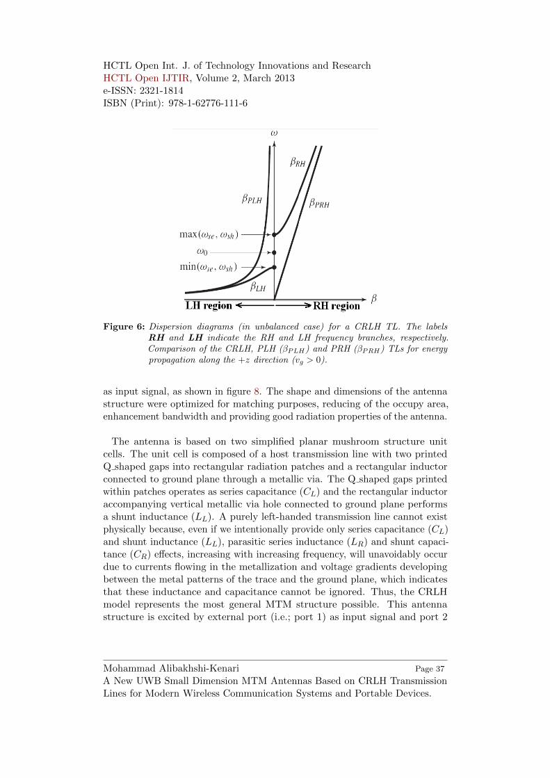
A metamaterial is usually a periodic structure with N identical unit cellscascading together, where each cell is much smaller than one wavelength atthe operational frequency. The composition of one metamaterial unit cell iscategorized as a series inductor (LR), series capacitor (CL), shunt inductor(LL), and shunt capacitor (CR). Shunt inductor (LL) and series capacitor (CL)determine the left-handed mode propagation properties, while series inductor(LR) and shunt capacitor (CR) govern the right-handed mode propagation prop-erties. The behaviour of both left-handed and right-handed mode propagationat different frequencies can be easily addressed in a simple dispersion diagram,as shown in figure 6. The dispersion curve on the β > 0 side is the right-handedmode, while the dispersion curve on the β < 0 side is the left-handed mode [9].The electrical size of a conventional transmission line is strongly related to itsphysical dimensions and thus reducing device size usually means increasingoperational frequency. To the contrary, the dispersion curve of a metamaterial isdetermined by the four CRLH parameters. This property implies the following:if these four parameters are realized in a very compact form, the correspondingcircuit size will be physically small but electrically large. This concept has beenadopted successfully in small antenna designs [7]-[25].
Ultra Wide Band and Small CRLH MTM ProposedAntennas Design
UWB and Compact CRLH MTM Printed Q-Shaped Two Unit CellsAntenna
The design of equivalent circuit model of the proposed MTM antenna is basedon the CRLH-TL structure shown in figure 7. The proposed planar antenna isfabricated on an Rogers RT Duroid5880 substrate, with a dielectric constant of2.2, and a thickness of 1.6 mm. This mushroom type unit cell consisted of a 10.8mm x 8.6 mm top patch, printed on top of the substrate and a rectangular induc-tor attending a metallic via hole. Each unit cell was coupled to its adjacent unitcell and the vertical via was connected between the rectangular inductor and theground on the back of the substrate. This antenna was excited by external port
Mohammad Alibakhshi-KenariA New UWB Small Dimension MTM Antennas Based on CRLH TransmissionLines for Modern Wireless Communication Systems and Portable Devices.
Page 36
HCTL Open Int. J. of Technology Innovations and ResearchHCTL Open IJTIR, Volume 2, March 2013e-ISSN: 2321-1814ISBN (Print): 978-1-62776-111-6
Figure 6: Dispersion diagrams (in unbalanced case) for a CRLH TL. The labelsRH and LH indicate the RH and LH frequency branches, respectively.Comparison of the CRLH, PLH (βPLH) and PRH (βPRH) TLs for energypropagation along the +z direction (vg > 0).
as input signal, as shown in figure 8. The shape and dimensions of the antennastructure were optimized for matching purposes, reducing of the occupy area,enhancement bandwidth and providing good radiation properties of the antenna.
The antenna is based on two simplified planar mushroom structure unitcells. The unit cell is composed of a host transmission line with two printedQ shaped gaps into rectangular radiation patches and a rectangular inductorconnected to ground plane through a metallic via. The Q shaped gaps printedwithin patches operates as series capacitance (CL) and the rectangular inductoraccompanying vertical metallic via hole connected to ground plane performsa shunt inductance (LL). A purely left-handed transmission line cannot existphysically because, even if we intentionally provide only series capacitance (CL)and shunt inductance (LL), parasitic series inductance (LR) and shunt capaci-tance (CR) effects, increasing with increasing frequency, will unavoidably occurdue to currents flowing in the metallization and voltage gradients developingbetween the metal patterns of the trace and the ground plane, which indicatesthat these inductance and capacitance cannot be ignored. Thus, the CRLHmodel represents the most general MTM structure possible. This antennastructure is excited by external port (i.e.; port 1) as input signal and port 2
Mohammad Alibakhshi-KenariA New UWB Small Dimension MTM Antennas Based on CRLH TransmissionLines for Modern Wireless Communication Systems and Portable Devices.
Page 37

HCTL Open Int. J. of Technology Innovations and ResearchHCTL Open IJTIR, Volume 2, March 2013e-ISSN: 2321-1814ISBN (Print): 978-1-62776-111-6
Figure 7: The equivalent circuit model of the proposed printed Q-shaped antennacomposed of two unit cells. A) For one unit cell, B) For whole structure.
is matched to 50Ω load impedance of the SMD1206 components connected toground plane through a metallic via hole. Configuration of the recommendedprinted Q-shaped two unit cells antenna is displaying in figure 8.
In this design procedure of the antenna, we employed MTM technologyand used printed planar technique, which results to downsizing of the proposedantenna, therefore, proposed antenna size is very compact in comparison toconventional antennas size. Presented antenna is formed of the two simplifiedplanar mushroom structure Q-shaped unit cells, each of which occupies only10.8 mm x 8.6 mm or 0.18λ0 x 0.15λ0 in terms of the free space wavelengthat the resonance frequency f = 5.2 GHz, therefore, the physical length, widthand height of this antenna are 21.6 mm, 8.6 mm and 1.6 mm, respectively, or,0.37λ0 x 0.15λ0 x 0.02λ0.
One important issue many conventional metamaterial antennas confront is
Mohammad Alibakhshi-KenariA New UWB Small Dimension MTM Antennas Based on CRLH TransmissionLines for Modern Wireless Communication Systems and Portable Devices.
Page 38

HCTL Open Int. J. of Technology Innovations and ResearchHCTL Open IJTIR, Volume 2, March 2013e-ISSN: 2321-1814ISBN (Print): 978-1-62776-111-6
Figure 8: Configuration of the proposed printed Q-shaped antenna constructed of thetwo unit cells. A) Top view, B) Isometric view.
a lack of bandwidth [26, 27]. Although many research articles have demon-strated the ability to design small antennas by using metamaterial technology,very little work has been done to address the bandwidth issue.
The transmission coefficient of the antenna system is an important frequencydomain indicator of the time domain performance of an UWB antenna [29]. Inthis paper, we proposed several efficient method to extend the bandwidth ofthe MTM antennas with a fixed antenna size. The points summarize in below,
Mohammad Alibakhshi-KenariA New UWB Small Dimension MTM Antennas Based on CRLH TransmissionLines for Modern Wireless Communication Systems and Portable Devices.
Page 39

HCTL Open Int. J. of Technology Innovations and ResearchHCTL Open IJTIR, Volume 2, March 2013e-ISSN: 2321-1814ISBN (Print): 978-1-62776-111-6
are guidelines for the UWB antenna design.
1. Travelling wave antennas or antennas having low Q can be very broadband.
2. Antennas incorporating tapers or rounded edges tend to give broad band-widths because surface currents have a smooth path to follow [30].
3. Linearly polarized transmit and receive antennas are the simplest toimplement in a compact planar package.
4. Minimizing the thickness of the substrate and using low loss materialsmaximizes radiation efficiency.
5. Using of the printed planar methodology into radiation patches for antennadesign with minimizing acceptable distance between gap edges results toextended the bandwidth of the antenna.
In this report, we using of the second, fourth and last proposed approachesfor increasing the bandwidth and radiation characteristics of the proposedantennas. By using a smaller value of the loaded series capacitance (CL) onthe CRLH-TL, broadband performance can obtain. A smaller value of theloaded series capacitance will be realized by implementation of the Q shapedgaps with closely space edges printed into rectangular patches of the radiationpatches. We used of this method to increase the bandwidth of the our antenna,as providing a ultra wideband (UWB) antenna with 6.6 GHz workable band-width (from 2.7 GHz to 9.3 GHz) for VSWR < 2, which corresponding to 110%bandwidth and also with employing uniform excitation mechanism by utilizingtwo port as first port is fed with input signal and second port is matchedto a 50 ohm load impedance of the SMD1206 resistance components whichthrough a vertical metallic via is connected to ground, the aperture efficiencyof the antenna can extend, thus, the antenna gain and radiation efficiency areincreased. The antenna gain and radiation efficiency at resonance frequencyfr = 5.2 GHz are equal to 4.71 dBi and 41.82%, respectively. The simulatedreflection coefficient (S11 < −10dB) of the presented antenna and too radi-ation gain pattern at fr = 5.2 GHz are plotted in figures ?? and ??, respectively.
For the exhibition of this MTM antenna with reduced size and extendedbandwidth, useful MTM antenna based on two simplified planar mushroomstructure unit cells is designed. The configuration of this small UWB CRLHMTM antenna employing the proposed methods is shown in figure 8. Theperformances of the presented methods and CRLH MTM antenna structure
Mohammad Alibakhshi-KenariA New UWB Small Dimension MTM Antennas Based on CRLH TransmissionLines for Modern Wireless Communication Systems and Portable Devices.
Page 40

HCTL Open Int. J. of Technology Innovations and ResearchHCTL Open IJTIR, Volume 2, March 2013e-ISSN: 2321-1814ISBN (Print): 978-1-62776-111-6
Figure 9: Simulated reflection coefficient (S11 < −10dB).
Figure 10: The radiation gain pattern in elevation plane (φ = 0o) and at resonancefrequency fr = 5.2 GHz. A) For two dimensional (2-D) case, B) For threedimensional (3-D) case.
are verified using Agilent ADS full-wave simulator. As an advantage of theproposed ways, (i.e.; employing MTM technology, printed planar patches, us-ing low loss materials maximizes radiation efficiency and suitable inductiveparameter consist of rectangular inductors and metallic via holes accompanyingtheir optimize values and optimized distance between gap edges), those arevery easy to implement small UWB MTM antennas by properly introducingthe CRLH-TL unit cells. The proposed printed Q-shaped antenna has much
Mohammad Alibakhshi-KenariA New UWB Small Dimension MTM Antennas Based on CRLH TransmissionLines for Modern Wireless Communication Systems and Portable Devices.
Page 41

HCTL Open Int. J. of Technology Innovations and ResearchHCTL Open IJTIR, Volume 2, March 2013e-ISSN: 2321-1814ISBN (Print): 978-1-62776-111-6
smaller size and wider bandwidth than conventional antennas. This antennacan support all cellular frequency bands from 2.7 GHz to 9.3 GHz, using singleor multiple feed designs, which eliminates the need for antenna switches. Allof these attributes make the fabricated Q-shaped two unit cells antenna wellsuitable for the modern communication units [7, 26].
Proposed Improvement Gain Antenna with Printed Q-ShapedFour Unit Cells Structure
In this section, we present the printed Q-shaped antenna structure that con-structed of four unit cells with enhancement bandwidth, radiation gain andefficiency in comparison to printed Q-shaped antenna structure proposed inprevious section. The design procedure of the proposed antenna in this part iscompletely same with design procedure of the presented Q-shaped antenna inprior section, but equivalent circuit model and geometry of the later antennastructure is different with first antenna structure prototype. This proposeddifference caused which later antenna providing enhancement bandwidth andimprovement radiation characteristics than first antenna designed. Presentedantenna in this section is designed as one rectangular inductor attending ametallic via are considered for each gap area which become one constructingone unit cell, in results this antenna composed of four unit cells as display infigure 12, in opposite, proposed antenna in previous section was designed as onerectangular inductor accompanying a vertical via considered for two gap areawhich together constructing one unit cell as first antenna consists of two unitcells and exhibited in figure 8. Equivalent circuit model for proposed antenna inthis section and previous section are shown in figures 7 and 11, respectively. Asobvious recent structure composed of four unit cells as each unit cell consist ofa series capacitance (CL) which created by printed Q-shaped gap capacitance,a shunt inductance (LL) that caused with a rectangular inductor connected toground plane through a metallic via hole as these capacitor an inductor playsleft-handed roles, also a series inductance (LR) which established by unavoidablecurrent flow on the patches and a shunt capacitance (CR) that performed withgap capacitor between patches and ground plane, as later inductor and capacitorcannot be ignored and portrays right-handed function.
This typical CRLH antenna structure consists of a feed line that is elec-tromagnetically coupled to metallic patches, rectangular inductors, metallic viaholes that connects the rectangular inductor to the ground plane. This feedline through a small gap excites the CRLH unit cells. Typically, the antennais matched to a port with 50 ohm load impedance. The resonant frequencies,
Mohammad Alibakhshi-KenariA New UWB Small Dimension MTM Antennas Based on CRLH TransmissionLines for Modern Wireless Communication Systems and Portable Devices.
Page 42

HCTL Open Int. J. of Technology Innovations and ResearchHCTL Open IJTIR, Volume 2, March 2013e-ISSN: 2321-1814ISBN (Print): 978-1-62776-111-6
Figure 11: The equivalent circuit model of the proposed printed Q-shaped antennaconstructed of four unit cells. A) For one unit cell, B) For whole structure.
matching of multiple right-handed and left-handed modes, and associated effi-ciencies can be controlled by changing and tuning the size of the cell patch, thewidth of the via line, the length of the feed line, the distance between the antennaelements and the ground, optimizing the rectangular inductor and various otherdimensions and layouts [7]-[17]. The gap capacitor and the rectangular inductoraccompanying a metallic via hole could be viewed as series capacitance CLand shunt inductance LL, while the top patch possessed the series inductanceLR and the shunt capacitance CR to the ground. Therefore, a left-handedresonance could be obtained at the desired frequency by properly designingthe gap capacitor and the rectangular inductor that connected to ground planethrough a vertical metallic via hole. Formation of the recommended antennawith enhancement bandwidth and improvement radiation properties is exhibitin figure 12.
As obvious, according to figure 12, we using four rectangular inductor whicheach through a metallic via connected to ground plane, that results to changing
Mohammad Alibakhshi-KenariA New UWB Small Dimension MTM Antennas Based on CRLH TransmissionLines for Modern Wireless Communication Systems and Portable Devices.
Page 43

HCTL Open Int. J. of Technology Innovations and ResearchHCTL Open IJTIR, Volume 2, March 2013e-ISSN: 2321-1814ISBN (Print): 978-1-62776-111-6
Figure 12: Formation of the proposed printed Q-shaped antenna constructed of thefour unit cells. A) Top view, B) Isometric view.
configuration of the unit cells and therefore changing configuration of thisantenna structure than antenna designed in figure 8. This varies, i.e.; increasenumber of rectangular inductor from two to four, decrease number of turnsof the rectangular inductor from two to one turn and too reduce width ofthe rectangular inductor than first case, results to changes frequency rangeand hence extend the bandwidth of this antenna, also, this varies caused toimprovement and increase of the radiation properties. Printed Q-shaped an-tenna which is designed on Rogers RT Duroid5880 substrate with dielectricconstant εr = 2.2 and thickness h = 1.6 mm has wider bandwidth and better
Mohammad Alibakhshi-KenariA New UWB Small Dimension MTM Antennas Based on CRLH TransmissionLines for Modern Wireless Communication Systems and Portable Devices.
Page 44

HCTL Open Int. J. of Technology Innovations and ResearchHCTL Open IJTIR, Volume 2, March 2013e-ISSN: 2321-1814ISBN (Print): 978-1-62776-111-6
radiation performances than prior antenna. Presented antenna is formed of thefour simplified planar mushroom structure Q-shaped unit cells, each of whichoccupies only 5.4 mm x 8.6 mm or 0.1λ0 x 0.16λ0 at the resonance frequencyfr = 5.65 GHz, where λ0 is free space wavelength, therefore, overall size ofthe Q-shaped antenna is 21.6 x 8.6 x 1.6 mm3 (0.4λ0 x 0.16λ0 x 0.03λ0). Thisantenna has 7.6 GHz applicable bandwidth from 4.1 GHz to 11.7 GHz forVSWR < 2, which corresponds to 96.2% practical bandwidth, in addition atresonance frequency fr = 5.65 GHz the antenna gain and radiation efficiencyare 6.52 dBi and 60.47%, respectively. The simulated return loss bandwidth(S11 parameter) of the antenna and radiation gain pattern at fr = 5.65 GHzare plotted in figures 13 and 14, respectively. The results shown that latterantenna has same physical size, broader bandwidth and superior radiationperformances in comparison to first antenna prototype. Both proposed antennahave smaller size and wider bandwidth attending higher radiation propertiesthan conventional antennas.
Entire equivalent circuit model and configuration of the both Q-shaped anten-nas, as first is constructed of two unit cells and second is composed of four unitcells, are illustrated in figures 7 and 11, and figures 8 and 12, respectively,as shown two proposed antenna have identical design procedures but differentequivalent circuit models and different layout structures. Two designed UWBsmall antennas based on CRLH MTM-TLs are suitable and useful for microwaveand portable devises and wireless communication applications.
Figure 13: Simulated return loss (S11 parameter).
Mohammad Alibakhshi-KenariA New UWB Small Dimension MTM Antennas Based on CRLH TransmissionLines for Modern Wireless Communication Systems and Portable Devices.
Page 45

HCTL Open Int. J. of Technology Innovations and ResearchHCTL Open IJTIR, Volume 2, March 2013e-ISSN: 2321-1814ISBN (Print): 978-1-62776-111-6
Figure 14: The radiation gain pattern in elevation plane (φ = 0o) and at resonancefrequency fr = 5.65GHz. A) For two dimensional (2-D) case, B) Forthree dimensional (3-D) case.
Simulation Results and Discussions of the ProposedPrinted Antennas
The antennas were designed on Rogers RT Duroid5880 substrates with εr =2.2 and thickness h = 1.6 mm. Each unit cell of the first and second proposedantenna respectively occupies only 10.8 mm x 8.6 mm and 5.4 mm x 8.6 mm andoverall size of the proposed antennas are equal to 21.6 mm x 8.6 mm x 1.6 mmand 21.6 mm x 8.6 mm x 1.6 mm, respectively. As obvious two antennas haveidentical overall size, but because both antennas composed of not equal numberof unit cells as first antenna constructed of two unit cells, however secondantenna build of four unit cells, therefore, each unit cell dimension of eachantennas are unequal. Figure 9 and figure 13, respectively shows the simulatedreturn losses (S11 parameters) of the printed Q-shaped antenna assembled oftwo unit cells and printed Q-shaped antenna organized of four unit cells. Thesimulated results were obtained using Agilent ADS full-wave simulator. Asillustrated in figure 9 the simulated return losses bandwidth (S11 < −10dB)of the first presented antenna is 6.6 GHz (from 2.7 GHz to 9.3 GHz), thiscorresponds to 110% practical impedance bandwidth, which is more than con-ventional antennas. The simulated return losses bandwidth (S11 < −10dB)of the second proposed antenna that shown in figure 13 is 7.6 GHz (from 4.1GHz to 11.7 GHz), which corresponds to 96.2% practical impedance bandwidth,which is more than conventional antennas. The simulated two dimensional (2-D)
Mohammad Alibakhshi-KenariA New UWB Small Dimension MTM Antennas Based on CRLH TransmissionLines for Modern Wireless Communication Systems and Portable Devices.
Page 46

HCTL Open Int. J. of Technology Innovations and ResearchHCTL Open IJTIR, Volume 2, March 2013e-ISSN: 2321-1814ISBN (Print): 978-1-62776-111-6
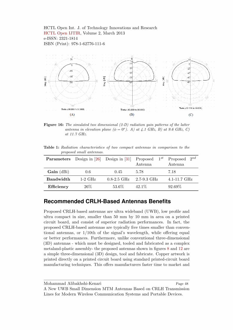
radiation gain patterns of the recommended antennas at different frequencyare plotted in figures 15 and 16, respectively. For first antenna, radiationgains are 2.8 dBi and 5.78 dBi, respectively, at 2.7 GHz and 9.3 GHz. Also,radiation efficiencies of this antenna are 37.23% and 42.1% at same frequencies,respectively. For second antenna, at 4.1 GHz, 9.6 GHz and 11.7 GHz, gain andefficiency are equal to 7.18 dBi and 92.69%, 5.83 dBi and 34.89%, and 5.42 dBiand 54.19%, respectively.
According to figures 15 and 16 radiation patterns are unidirectional character-
Figure 15: The simulated two dimensional (2-D) radiation gain patterns of the Q-shaped antenna constructed of two unit cells in elevation plane (φ = 0o).A) at 2.7 GHz, B) at 9.3 GHz.
istics. The peak gain and radiation efficiency of the first and second antennasoccurs at 9.3 GHz and 4.1 GHz, respectively, and are equal to 5.78 dBi and42.1%, and 7.18 dBi and 92.69%, respectively. The simulated three dimensional(3-D) radiation gain patterns of the presented antennas at different frequenciesare plotted in figures 17 and 18, respectively. To validate the design proceduresthe proposed antennas were compared with several compact and UWB antennasand their radiation characteristics and their dimensions were summarized inTable 1 and Table 2, respectively.
Mohammad Alibakhshi-KenariA New UWB Small Dimension MTM Antennas Based on CRLH TransmissionLines for Modern Wireless Communication Systems and Portable Devices.
Page 47
HCTL Open Int. J. of Technology Innovations and ResearchHCTL Open IJTIR, Volume 2, March 2013e-ISSN: 2321-1814ISBN (Print): 978-1-62776-111-6
Figure 16: The simulated two dimensional (2-D) radiation gain patterns of the latterantenna in elevation plane (φ = 0o). A) at 4.1 GHz, B) at 9.6 GHz, C)at 11.7 GHz.
Table 1: Radiation characteristics of two compact antennas in comparison to theproposed small antennas.
Parameters Design in [26] Design in [31] Proposed 1st
AntennaProposed 2nd
Antenna
Gain (dBi) 0.6 0.45 5.78 7.18
Bandwidth 1-2 GHz 0.8-2.5 GHz 2.7-9.3 GHz 4.1-11.7 GHz
Efficiency 26% 53.6% 42.1% 92.69%
Recommended CRLH-Based Antennas Benefits
Proposed CRLH-based antennas are ultra wideband (UWB), low profile andultra compact in size, smaller than 50 mm by 10 mm in area on a printedcircuit board, and consist of superior radiation performances. In fact, theproposed CRLH-based antennas are typically five times smaller than conven-tional antennas, or 1/10th of the signal’s wavelength, while offering equalor better performances. Furthermore, unlike conventional three-dimensional(3D) antennas - which must be designed, tooled and fabricated as a complexmetaland-plastic assembly- the proposed antennas shown in figures 8 and 12 area simple three-dimensional (3D) design, tool and fabricate. Copper artwork isprinted directly on a printed circuit board using standard printed-circuit boardmanufacturing techniques. This offers manufacturers faster time to market and
Mohammad Alibakhshi-KenariA New UWB Small Dimension MTM Antennas Based on CRLH TransmissionLines for Modern Wireless Communication Systems and Portable Devices.
Page 48

HCTL Open Int. J. of Technology Innovations and ResearchHCTL Open IJTIR, Volume 2, March 2013e-ISSN: 2321-1814ISBN (Print): 978-1-62776-111-6
Figure 17: The simulated three dimensional (3-D) radiation gain patterns of the firstantenna in elevation plane (φ = 0o). A) at 2.7 GHz, B) at 9.3 GHz.
Figure 18: The simulated three dimensional (3-D) radiation gain patterns of the Q-shaped antenna composed of four unit cells in elevation plane (φ = 0o).A) at 4.1 GHz, B) at 9.6 GHz, C) at 11.7 GHz.
reduced bills-of-materials due to the simplified design. It also offers a greatly
Mohammad Alibakhshi-KenariA New UWB Small Dimension MTM Antennas Based on CRLH TransmissionLines for Modern Wireless Communication Systems and Portable Devices.
Page 49

HCTL Open Int. J. of Technology Innovations and ResearchHCTL Open IJTIR, Volume 2, March 2013e-ISSN: 2321-1814ISBN (Print): 978-1-62776-111-6
reduced need for fabrication and assembly of antenna components.
In addition, the CRLH-based antenna’s ability to concentrate electromagneticfields and currents near their antenna structures results in achieving betterperformance.
Table 2: Dimension of some of the UWB antennas in comparison to the proposedUWB antennas
Some of the UWB Monopole Antennas Size of Antenna
Slotted planar binomial monopole antenna [32] 30 x 27.4 x 1 mm3
Slotted circular monopole antenna [33] 26 x 27 x 1 mm3
Slotted rectangular monopole antenna [34] 18 x 20 x 1 mm3
Fork shaped antenna [35] 35 x 30 x 0.769 mm3
Slotted arc shaped edge rectangular antenna [36] 24 x 35 x 0.8 mm3
Both proposed UWB antennas in this article 21.6 x 8.6 x 1.6 mm3
Conclusion
CRLH transmission line metamaterials represent a paradigm shift in electro-magnetics engineering and, in particular, for antennas. They exhibit exceptionalproperties, resulting from their rich dispersion and their fundamental left/right-hand duality. They offer simple and deep insight into metamaterial phenomena,and provide efficient tools for the practical design of components and antennas.
In this paper, we introduced a new concept of antenna size reduction basedon metamaterial design technology and printed planar methodology, and alsopresented a novel idea of antenna bandwidth enhancement and radiation’sproperties improvement based on employing appropriate inductive elementsaccompanying their optimize values and using low loss materials maximizesradiation efficiency. All simulated results demonstrated that the proposedCRLH-based antennas have superior performances and smaller size comparedto other conventional antennas designs. These antennas have the advantages ofsmall size, UWB, lightweight, high gain and efficiency, unidirectional radiationpatterns, simple implementation and low cost. The simulated results exhibitthat the proposed antennas should be potential candidates to use in the modern
Mohammad Alibakhshi-KenariA New UWB Small Dimension MTM Antennas Based on CRLH TransmissionLines for Modern Wireless Communication Systems and Portable Devices.
Page 50

HCTL Open Int. J. of Technology Innovations and ResearchHCTL Open IJTIR, Volume 2, March 2013e-ISSN: 2321-1814ISBN (Print): 978-1-62776-111-6 References
wireless communication systems and portable devices.
Acknowledgement
The author would like to express his sincere thanks to Research Institute forICT of Iran (Contract number 6987/500/T), the microwave and millimeter wavelaboratory of the Amirkabir University of Technology (Tehran Polytechnic) andthe antenna laboratory of the K. N. Toosi University of Technology.
References
[1] C. Caloz and T. Itoh, Electromagnetic Metamaterials:
Transmission Line Theory and Microwave Applications, NewYork: Wiley, 2006.
[2] N. Engheta and R. W. Ziolkowski, Metamaterials: Physics and
Engineering Explorations, New York: Wiley, 2006.
[3] Anon., FCC First Report and Order on Ultra Wideband
Technology, Feb. 2002.
[4] Y.J. Wang, et al., Novel Microstrip-Monopole Integrated
Ultra-Wideband Antenna For Mobile UWB Devices, Radio andWireless Conference Proceedings, pp. 87-90, 2003.
[5] Takuya Taniguchi and Takehiko Kobayashi, An Omnidirectional
and Low-VSWR Antenna for the FCC-Approved UWB Frequency Band,IEEE Int’l Symposium on Antennas and Propagation, Columbus, OH,Vol.3, pp. 460-463, June, 2003.
[6] W. Sorgel, C. Waldschmidt, and W. Wiesbeck, Transient response of
a Vivaldi antenna and a logarithmic periodic dipole array for
ultra wideband communication, IEEE Int’l Symposium on Antennasand Propagation, Columbus, OH, Vol.3, pp, 592-595, June, 2003.
[7] C. J. Lee, M. Achour, and A. Gummalla, Compact Metamaterial High
Isolation MIMO Antenna Subsystem, in proc. Asia Pacific MicrowaveConference, pp. 1-4, 2008.
[8] C. J. Lee, A. Gummalla, and M. Achour, Compact Dualband Antenna
Subsystem for MIMO Application, International Workshop on Antenna
Mohammad Alibakhshi-KenariA New UWB Small Dimension MTM Antennas Based on CRLH TransmissionLines for Modern Wireless Communication Systems and Portable Devices.
Page 51

HCTL Open Int. J. of Technology Innovations and ResearchHCTL Open IJTIR, Volume 2, March 2013e-ISSN: 2321-1814ISBN (Print): 978-1-62776-111-6 References
Technology: Small Antennas and Novel Metamaterials, iWAT 2009, March2-4, 2009, pp. 1-4.
[9] C. Caloz and T. Itoh, Electromagnetic Metamaterials:
Transmission Line Theory and Microwave Applications, TheEngineering Approach, New York, John Wiley & Sons, 2005.
[10] R. A. Shelby, D. R. Smith, and S. Schultz, Experimental Verification
of a Negative Index of Refraction,” Science, 292, 55 14, 2001, pp.77-79.
[11] A. Lai, C. Caloz, and T. Itoh, Composite right/left-handed
transmission line metamaterials, IEEE Microw. Mag., vol. 5, no. 3,pp. 3450, Sep. 2004.
[12] F. J. Herraiz-Martnez, V. Gonzlez-Posadas, L. E. Garcia-Munoz, andD. Segovia-Vargas, Multi-frequency and dual-mode patch antennas
partially filled with left-handed structures, IEEE Trans. Anten-nas Propag., vol. 56, no. 8, pp. 25272539, Aug. 2008.
[13] S. G. Mao, S. L. Chen, and C. W. Huang, Effective electromagnetic
parameters of novel distributed left-handed microstrip lines,IEEE Trans. Microw. Theory Tech., vol. 53, no. 4, pp. 15151521, Apr.2005.
[14] C. Caloz and T. Itoh, Novel microwave devices and structures
based on the transmission line approach of meta-materials, inIEEE MTT-S Int’l Microw. Symp. Dig., Jun. 2003, pp. 195198.
[15] Y. M. Pan and S. J. Xu, A new leaky wave antenna based on channel
guide filled with left-hand material for millimeter-wave
applications, Int. J. Infrared Millim. Waves, vol. 27, no. 11, pp.14571468, 2006.
[16] A. Sanada, C. Caloz, and T. Itoh, Zeroth order resonance in the
left-handed transmission line, IEICE Trans. Electron., vol. 87-C, no.1, pp. 17, Jan. 2004.
[17] W. Huang, N. Xu, V. Pathak, G. Poilasne, and M. Achour, CompositeRight-Left Handed Metamaterial Ultra-Wideband Antenna, Int’lWorkshop on Antenna Technology: Small Antennas and Novel Metamate-rials, iWAT 2009, March 2-4, 2009, pp. 1-4.
Mohammad Alibakhshi-KenariA New UWB Small Dimension MTM Antennas Based on CRLH TransmissionLines for Modern Wireless Communication Systems and Portable Devices.
Page 52

HCTL Open Int. J. of Technology Innovations and ResearchHCTL Open IJTIR, Volume 2, March 2013e-ISSN: 2321-1814ISBN (Print): 978-1-62776-111-6 References
[18] C. Caloz and T. Itoh, Electromagnetic Metamaterials, Transmission Line
- Theory and Microwave Applications, Piscataway, John Wiley/IEEEPress, 2005.
[19] N. Engheta and R. W. Ziolkowski (eds.), Electromagnetic
Metamaterials: Physics and Engineering Explorations, Pis-cataway, John Wiley/IEEE Press, 2006.
[20] C. Caloz and T. Itoh, Application of the Transmission Line
Theory of Left-Handed (LH) Materials to the Realization of a
Microstrip LH Transmission Line, IEEE International Symposium onAntennas and Propagation Digest, San Antonio, USA, June 2002, pp.412-415.
[21] A. K. Iyer and G. V. Eleftheriades, Negative Refractive Index
Metamaterials Supporting 2-D Waves, IEEE International Symposiumon Microwave Theory and Techniques Digest, Seattle, USA, June 2002, pp.1067-1070.
[22] C. Caloz and T. Itoh, Novel Microwave Devices and Structures
Based on the Transmission Line Approach of Meta-Materials,IEEE International -Symposium on Microwave Theory and TechniquesDigest, Philadelphia, USA, June 2003, pp. 195-198.
[23] R. E. Collin and F. J. Zucker (eds.), Antenna Theory, New York, McGrawHill, 1969, Chapters 19 and 20.
[24] G. V. Eleftheriades and K. G. Balmain, Negative Refraction
Metamaterials: Fundamental Principles and Applications, NewYork, John Wiley & Sons, 2005.
[25] C. J. Lee, K. M. H. Leong, and T. Itoh, Broadband Small Antenna for
Portable Wireless Application, International Workshop on AntennaTechnology: Small Antennas and Novel Metamaterials, iWAT 2008, March4-6, 2008, pp. 10-l3.
[26] C. J. Lee, K. M. K. H. Leong, and T. Itoh, Composite right/left-handed
transmission line based compact resonant antennas for RF
module integration, IEEE Trans. Antennas and Propagation, vol. 54,no. 8, pp. 2283-2291, Aug. 2006.
[27] M. Schussler, J. Freese, and R. Jakoby, Design of Compact Planar
Antenna Using LH-Transmission Lines, IEEE MTT-S International Mi-crowave Symposium, 1, June 2004, pp. 209-2 12.
Mohammad Alibakhshi-KenariA New UWB Small Dimension MTM Antennas Based on CRLH TransmissionLines for Modern Wireless Communication Systems and Portable Devices.
Page 53

HCTL Open Int. J. of Technology Innovations and ResearchHCTL Open IJTIR, Volume 2, March 2013e-ISSN: 2321-1814ISBN (Print): 978-1-62776-111-6 References
[28] E. Weber and F. Nebeker, The Evolution of Electrical Engineering,presented at IEEE Press, Piscataway, New Jersey USA, 1994.
[29] Q.Ye., Time Domain Response of Ultra-wideband Dipole Antennas,2004 Antem/URSI Conference on Antenna Technology and Applied, Elec-tromagnetics Ottawa, Canada. July 2004. pp.661-664.
[30] E. Gazit Improved Design of the Vivaldi Antenna, IEEE Trans. Ant.Prop. Vol.135, 1988.
[31] Y. Li, Z. Zhang, J. Zheng and Z. Feng, Compact heptaband
reconfigurable loop antenna for mobile handset, IEEE Antennasand Wireless Propagation Letters, vol. 10, pp. 1162- 1165, 2011.
[32] Y. L. Zhao, Y. C. Jiao, G. Zhao, L. Zhang, Y. Song, and Z.B. Wong, Compact planar monopole UWB antenna with band-notched
characteristic, Microw. Opt. Technol. Lett., vol. 50, no. 10, pp.26562658,Oct. 2008.
[33] R. Movahedinia and M. N. Azarmanesh, A novel planar UWB monopole
antenna with variable frequency band-notch function based on
etched slot-type ELC on the patch, Microw. Opt. Technol. Lett.,vol.52, no. 1, pp. 229232, Jun. 2010.
[34] M. Abdollahvand, G. Dadashzadeh, and D. Mostafa, Compact
dualband-notched printed monopole antenna for UWB
application, IEEE Antennas Wireless Propag. Lett., vol. 9, pp.11481151, 2010.
[35] S. J. Wu, C. H. Kang, K. H. Chen, and J. H. Tarng, Study of an ultra
wideband monopole antenna with a band-notched open-looped
resonator, IEEE Trans. Antennas Propag., vol. 58, no. 6, pp.18901897,Jun. 2010.
[36] C.-Y. Hong, C.-W. Ling, I.-Y. Tarn, and S.-J. Chung, Design of a planar
ultra wideband antenna with a new band-notch structure, IEEETrans. Antennas Propag., vol. 55, no. 12, pp. 33913397, Dec. 2007.
[37] Christophe Calm, Tatsuo Itoh and Andre Rennings, CRLH
Metamaterial Leaky-Wave and Resonant Antennas, IEEE Antennas
and Propagation Magazine, Vol. 50, No. 5, October 2008.
Mohammad Alibakhshi-KenariA New UWB Small Dimension MTM Antennas Based on CRLH TransmissionLines for Modern Wireless Communication Systems and Portable Devices.
Page 54

HCTL Open Int. J. of Technology Innovations and ResearchHCTL Open IJTIR, Volume 2, March 2013e-ISSN: 2321-1814ISBN (Print): 978-1-62776-111-6 References
This article is an open access article distributed under the terms and con-ditions of the Creative Commons Attribution 3.0 Unported License (http://creativecommons.org/licenses/by/3.0/).
c©2013 by the Authors. Licensed and Sponsored by HCTL Open, India.
Mohammad Alibakhshi-KenariA New UWB Small Dimension MTM Antennas Based on CRLH TransmissionLines for Modern Wireless Communication Systems and Portable Devices.
Page 55