a twt amplifier with a linear power transfer ...transfer characteristic and improved efficiency ......
TRANSCRIPT

NASA Technical Memorandum
A TWT Amplifier With a Linear PowerTransfer Characteristic andImproved Efficiency
iSA-TM- & *« AMELIFIZE WITH A S84-2 1803LINEAR POMER TRANSFER CHARACI ERISTIC AND
"""" (BASS) '2 P101 G3/33
Henry G. KosmahlLewis Research CenterCleveland, Ohio
and
John C. PetersonHughes Aircraft CompanyTorrance, California
Prepared for theTenth Communications Satellite Systems Conferencesponsored by the American Institute of Aeronautics and AstronauticsOrlando, Florida, March 18-22, 1984
NASA
https://ntrs.nasa.gov/search.jsp?R=19840013735 2020-05-15T18:11:57+00:00Z

ERRATA
NASA Technical Memorandum 83590
A TWT AMPLIFIER WITH A LINEAR POWER TRANSFERCHARACTERISTIC AND IMPROVED EFFICIENCY
Henry G. Kosmahl and John C. PetersonMarch 1984
Cover: The TM number should be 83477.
Report documentation page, block 1: The TM number should be 83477.

OF POOR QUALITY
A TWT AMPLIFIER WITH A LINEAR POWER TRANSFER CHARACTERISTIC ANDIMPROVED EFFICIENCY
Henry G. Kosmahl*National Aeronautics and Space Administration
Lewis Research CenterCleveland, Ohio 44135
and
John C. PetersonHughes Aircraft Company, EODTorrance, California 90509
Abstract
A novel method to linearize the POU* versusP,n power transfer characteristic of TWTs bystrictly internal modifications to the phasevelocity of the slow wave circuit is described.The AM to AM characteristic approaches then thatof a hard limiter and with a significantlyimproved intrinsic efficiency (1 to 2 dB) whilethe AM to PM conversion is not much different fromthat in an unmodified TWT, e.g. not exceeding3°/dB. Work is in progress to develop techniquesthat will reduce this AM to PM conversion tosmaller values. The theory of the "DynamicVelocity Taper" (DVT) is introduced and applied tocompute two different TWT's. The computed andmeasured power transfer characteristics of thesetwo TWT's - one a Ku Band and the other a Ka BandTWT for broadcasting from space - are shown intheir unmodified and modified form with theirrespective DVTs. The basic scheme of the DVT isthe continueous and dynamic synchronization of thephase velocity on the TWT circuit with theconditions on the spent beam accomplishedinternally in the TWT.
A 4-minute movie contrasting the bunchingphenomena in a TWT without and with a DVT will beshown.
An attempt is made to compare the advantagesof an internal Velocity Taper - perhaps incombination with an external and simple phaselinearizer-against active or passive predistortiontechniques.
Theory of the Dynamic Velocity Taper
The idea and pursuit of a linear anddistortion free amplifier is obviously not new.Until now, most attempts to eliminate or to reducethe nonlinearities in the AM to AM and AM to PMtransfer characteristics were directed totechniques external to the TWTs by passivepredistortion techniques or active feedbacks. Afew cases were reported, without however muchdetail, about discretely placed positive andnegative velocity tapers* such as to obtainimproved intrinsic efficiencies associated withlow distortions without achieving linearity. Themethod to be described in this paper addressesdirectly the problem of achieving internally alinear power transfer characteristic approachingthat of an ideal hard limiter, together with anefficiency improvement by 1 to 2 dB. Theeresulting AM to PM conversion of about 30° can be
accepted in some applications or be combined witha much simpler phase equalizer that provides analmost negligible phase shift. In addition,efforts are being made to develop new techniquesthat will retain the hard limiter characteristicswith increased efficiency but reduce the total AMto PM conversion to small values.
To understand the technique it is useful andnecessary to briefly review the small signaltheory of TWT's, that Pierce developed anddescribed with the help of several fundamentalparameters listed below?:
- gain and efficiency parameter
- velocity parameter
uQ, vQ - initial electron and circuit phasevelocities, respectively
b(z) u - v(z)Cv(z) - dynamic velocity parameter
Observe that one dimensional theories, such assmall signal theory of Pierce, use differentlydefined values for b, C, and Z from those usedin multidimensional programs.
Consider now a typical AM to AM power transfercurve of a communication - type TWT such as thecurves 1n fig. 1 marked w/o taper. The straightline region from origin up to about 6 to 10 dBbelow saturation covers a range of at least 25 dBof small signal gain. In this region a bunch hasbeen formed and assumed a favorable phase locationfor production of power. However, in every smallsignal region both the amount of energy extractionand the velocity spread within the bunch are, bydefinition, negligible; the small signal gain isprecisely predictable and corresponds directly tothe velocity parameter b0. As the small signalregion ends the bunch begins to lose slowly energy
to the wave. Looking at b it may be
b0 decreases
neTTow IEEE.
seen readily that as u0 decreasestoo, the favorable synchronization between beam andwave deteriorates, the gain slope decreases moreand more until saturation is reached. Anotherreason for this behavior is, of course, thedevelopment of an increasing velocity spread inthe bunch. To prevent the small signal gain slopefrom falling we have to keep b0 constant.

ORISiNALOF POOR QUAUTV"
Obviously, since one cannot prevent UQ fromdecreasing (we want the electrons to give up theirenergy), v must be decreased such as to keep b0approximately constant. We thus write
u - v(z) (1)
This nonlinear TWT interaction Eq. (1) can besolved only with a modern high speed computer: Asthe internal conversion efficiency increases withdistance, u decreases but this decrease iscompensated by a reduction in v(z).Mathematically, this is implemented by making bvariable:
Since the electron velocity distribution as afunction of energy extraction (distance) is knownin the program we select the parameter a such asis necessary to maintain the gain linear byslowing the velocity v(z) in a relation to theloss of energy or increase in efficiency. Thecomputed and typical dependence of n(z) on thelocation Z along the (unmodified) TWT with theinput power as parameter is shown in Fig. 4.Were n(z) a strickly exponential function of Z,as it is in the small signal region, we wouldobtain straight lines. Since the deviations fromlinearity are small, except at saturation, we arejustified to put
n(z)*er(Z-Z
-l r(Z-Z0)(3)
Z0 is the value of z at which the intended taperis to begin. From Eq. (2) and (3) we can write
(4)
And from Eq. (1) we get
1 + Cbo dv/dz 1 dv/dz- UT T -777
Equating Eq. (4) and (5) and multiplying bydz
/c>{5)
dzorC(Z - Z0)fl +£ (Z - Z0)
The integration of Eq. (6) gives
v(z) = voexp -a rC(Z - ZQ)
dv_v
- Z
(6)
(7)
Now, in the nondispersive region of a helix orother periodic slow wave structures we may write,approximately
(8)
where c is the speed of light, p the pitch anda the helix radius.
From Eq. (7) and (8) it follows
p = P0 exp ]- orC(Z - ZQ)H - Zo> +
"I(9)
for 2 > 10 and p = p0 at Z = Z0.
Approximately we get from Eq. (9) fora r C ( Z - Z0) « 1
f 2 2P = P0 1 - arC(Z - ZQ) - «c£ (Z - Z0)
+ a2C2r2(Z - Z)2 + -
The taper should be placed after the smallsignal region, because too "early" a placement isdistructive to the performance.
It is useful to calculate two other quantitiesof interest in designing tapers for linearized TWTs.
From Eq. (8) it follows directly for the localchange in pitch
dp = =2?- dv •= - —• Cv db = - ̂ 2itaCadn = - p.CadnC C C 0
The total change in the pitch 1s:
v.
(10)
/s odp = - 2»a —— Ca f dn
P0 n(Zo)
= -2na — Ca(n - n0)
where saturation occurs at Z = Zc
The number of turns in the tapered section isgiven by
and
Obviously, N - N0 is the difference in thenumber of turns
with v = VQ at Z = ZQ.

ORIGINAL'OF POOR QUALITY
Discussion of Results
Figures 1, 2, and 5 show AM to AM and AM to PMtransfer curves for the H8802 and H918 TWTs at 50watts/12 GHz and at 75 W/20 GHz, respectively.For the unmodified and tapered TWTs measuredcurves are shown and compared with computedresults on the H8802 experimental TWT built with aDVT. The existing discrepancy between thepredicted and measured power for both cases - withand without the DVT - is largely due to the use of"cold" measured helix loss values for thecomputation of losses in the operational ("hot")TWT instead of actual, "hot" loss values. Thelatter are best determined by pulsed, low dutycycle RF power measurements against CWmeasurements. The heating up of the outputsection of helices causes appromixately 0.5 dBreduction in power output of 12 GHz.
Figure 3 shows the RF basic efficiency polttedversus the helix (cathode) voltage for the H8802with and w/o the DVT. Note that higher voltagecorresponds to higher beam velocity, higher bvalue and consequently higher power output. Notealso that the TWT with DVT shows 16 percentefficiency - that is 5 p.c. points more than theTWT w/o DVT because higher efficiencies than intubes w/o DVT are being achieved at lower voltagesand lower b values, b » o, which produce smallerphase shift and a flatter, 0 slope gain responsewhile the TWT w/o DVT shows a S.S. gain slope of1.6 dB/GHz, as shown in Fig. 6. Note also thatthe improvement in efficiency that is due to theDVT is very significant and amounts at a givenvoltage to about 1.5 dB for the H8802 TWT. Thedegree of improvement depends, of course, onseveral design parameters.
The computed linearity of the AM to AM plotscan be seen to approach the shape of a hardlimiter. The AM to PM conversion is showncomputed and measured for the H8802 only that wasaugmented with DVT. We know that, as may beexpected, the helix with the DVT has a phase delayof about 30° but the total gain is also larger andthe measured curves never exceed the 3.0°/dBslope. Another interesting point in this contextis the question where to place the saturation onthe curve approaching the flat top of a hardlimiter. If that point were moved close to theknee the phase shift would become smaller.
At this time, a brief discussion of merits anddisadvantages of predistortion techniques and/oractive feedback alternatives to the velocity taperseems appropriate. Some points are obvious: thevelocity taper, being an internal modification tothe TWT, adds no weight or complexity, does notincrease the cost and offers substantial bandwidth(> 10 percent) without any tuning. All properlydesigned negative velocity tapers (that is v(z)decreasing with distance), produce an efficiencyimprovement - an important benefit not availablefrom any feedback system. In the case of a DVT aclosely linear AM to AM characteristic may beobtained together with an improvement of 1 to 2 dBin efficiency. With an RF efficiency above 16percent, a well designed multistage DepressedCollector (MDC) that has graphite, very lowsecondary emission electrodes, should raise theoverall efficiency above the 50 percent level. Afuture replacement of BeO rods with Diamond 2Arods is likely to result in overall efficienciesaround 65 percent since both losses are reducedand the impedance much increased.
Such improvements will make future TWTs aslinear as Solid States Amplifiers but with anefficiency far above any present and potentialability of FETS.
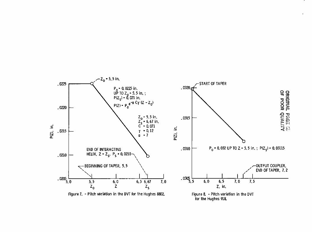
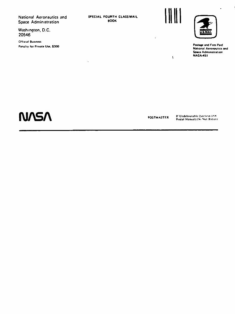
Figures 7 and 8 shows the pitch variationthe DVT computed for the H8802 and H918 TWTS,respectively.
in
An expansion of the present method to includea simple passive phase cancellation devices, inaddition to the DVT in the output section, isunder study at Hughes EDD. Some results of thiswork may be available for the March AIAApresentation.
A 4-minute movie that visualizes the bunchingphenomena in untapered TWT's and in those having aDVT will be shown.
References
1. Collomb, J., Gosset, P., and Raye, H.: "A NewGeneration of Satellite Traveling-Wave Tubesfor TV-Broadcasting and Telecommunications,"AIAA Paper 80-0485, April 1980.
2. Pierce, J.R., Traveling Wave Tubes, VanNostrand, New York, 1950.

Op POOR QUALITY
o:LU
I^—
o.i—
O
0
-5
-10
-15
-20
-25
-30
-35
S1•o
o
CO<:Q.
UJ
25
0
-25
-50
-75
-100
-125
-150
-175-200
MEASUREDWITH DVT7
COMPUTED /WITHDVT-7/ 14dB
3.2dB-,/ r
'OUT'PHASED
*- WITHOUT DVT
H WITH DVT
POWER TRANSFER
-50 0 5-40 -30 -20 -10INPUT POWER. P(N. dB
Figure 1. -Hughes 8802 experimental 12 GHz TWT. AM/AM andAM/PM conversion on a double decibel scale with and withoutDVT.

ORSGPAL WOF POOR QUALITY
20
18
16
14^
£ 12iCJ
i 10
D TWT WITHOUT DVT(OPERATING AT 3% OVER VOLTAGE)
O TWT WITH DVT(OPERATING AT 0% OVER VOLTAGE)
I I-18 -14 -10 -6 -2 SAT 2
RF INPUT POWER. dB10
Figure 2. - Basic efficiency measured versus power inputwith and without DVT, for the Hughes 880a

ORIGINALOF POOR QUALITY
o
18
16
14
12
§ 10oo
CO
D TWT WITHOUT DVTO TWT WITH DVT MEASURED
SYNCHRONOUSVOLTAGEBOTH CASES
I I I4/100 -5500 -5600 -5700 -5800 -5900 -6000
CATHODE POTENTIAL. V
Figure 3. - Basic efficiency versus voltage with andwithout DVT for the Hughes 8802, measured.

ORSG3NAL PAGE EUOF POOR QUALITY
10
a. icc l
er
.1
r r
^OUTPUT/ COUPLER
4 6Z, in.
10
Figure 4 - Basic efficiency versus distance along the helixwith power input as parameter.

ORIGINAL PA l̂ E3OF POOR QUALITY
76 WWITH DVT
WITHOUT TAPER
I I10 60 7020 30 40 50
P|NPUT. RELATIVE UNITS
Figures. - Power transfer characteristic for the Hughes 918with and without the DVT. (Computed.)

ORIG5NALOF POOR QUALITY
CO
P|NPUT=27-9dBm
''OUTPUT02-85'18"1
-TWT WITH DVT
11.7
-TWT WITHOUT DVT
0.2dB
P.MR. -7.2dBm
0.2 dB
vzP.MR. -8.0dBm
12.2FREQUENCY. GHz
Figure 6. - Gain variation for the Hughes 8802 with andwithout the DVT. (Measured.)
.0225
.0220
~- .0215BO_
.0210
. 0205.5.0
-Z0 = 5.5 in.
P0 • 0.0225 in.UP TO Z0 -5.5 in.;"- ",021 in.
e - aCy(Z-Z 0 )P(ZS) • 0~. 021 in.
Z 0 = 5 . 5 i n .
END OF INTERACTINGHELIX.
-BEGINNING OF TAPER, 5.5 \
1 I I5.5^n
6.0Z
6.5 6.67 7.0Zc
Figure 7. - Pitch variation in the DVT for the Hughes 8802.
.0320/-START OF TAPER
.0315
.0310
o o-n 3)•0 O
§820 f
•O igc &
— Pn - 0.032 UP TO Z • 5.5 in.; P(Z.) • 0.03115
-OUTPUT COUPLER.END OF TAPER, 7.2
.5 6.0 6.5 7.0 7.5Z, in.
Figure a - Pitch variation in the DVTfor the Hughes 91&

1 Report No NASA TM- *&3 // f "Sovernment Accession No
AIAA-84-0762 I
3 Recipient's Catalog No
4 Title and Subtitle 5 Report Date
A TWT Amplifier With a Linear Power TransferCharacteristic and Improved Efficiency 6 Performing Organization Code
506-62-527 Author(s)
Henry G. Kosmahl and John C. Peterson
8 Performing Organization Report No
E-179310 Work Unit No
9 Performing Organization Name and Address
National Aeronautics and Space AdministrationLewis Research CenterCleveland, Ohio 44135
11 Contract or Grant No
12 Sponsoring Agency Name and Address
National Aeronautics and Space AdministrationWashington, D.C. 20546
13 Type of Report and Period Covered
Technical Memorandum14 Sponsoring Agency Code
15 Supplementary Notes
Henry G. Kosmahl, NASA Lewis Research Center; John C. Peterson, Hughes AircraftCompany, EDO, Torrance, California 90509. Prepared for the Tenth CommunicationsSatellite Systems Conference sponsored by the American Institute of Aeronauticsand Astronautics, Orlando, Florida, March 18-22, 1984.
16 Abstract
A novel method called "Dynamic Velocity Taper" to linearize the Pout versusPin transfer characteristic that does not require any extraneous circuitryor tuning, has large bandwidth capabilities (> 10 percent) and offers also anincrease in the intrinsic TWT efficiency by 1 to 2 dB is described. Inaddition, the method permits the TWT to be operated at or near the synchronousvoltage (b = o) which produces a flat small and large signal gain responsesand low AM to PM conversion. The physics of the method and experimentalverification are given. The implementation should have a significant impacton TWT performance and increase the channel capacity of communicationsatellites.
17 Kay Words (Suggested by Authors))
TWT
Li nearizedHigher efficiency
IB Distribution Statement
Unclassified - unlimitedSTAR Category 33
9 Security Classlf (of this report)
Unclassif ied
20. Security Claaslf. (of this page)
Unclassified
21 No. of pages 22 Price'
'for sale by the National Technical Information Service, Springfield, Virginia 22161
National Aeronautics andSpace Administration
Washington, D.C.20546
Official Business
Penally tor Private Use. $300
SPECIAL FOURTH CLASS MAILBOOK
Pottage and Fees PaidNational Aeronautics andSpace AdministrationNASA-451
IW\SA POSTMASTER If Undehverahle (Srrnon I SHPostal Manual) IV) Not Return