aait, school of civil and environmental engineering ... web viewaait, school of civil and...
TRANSCRIPT
AAiT, School of Civil and Environmental Engineering Reinforced Concrete I
CHAPTER 3. LIMIT STATE DESIGN FOR SHEAR
3.1. THEORETICAL BACKGROUND
3.1.1. DIAGONAL TENSION IN HOMOGENEOUS ELASTIC BEAMS
The stresses acting in homogenous beams can be derived from mechanics of elastic materials. Shear stresses
(1)
act at any section in addition to the bending stresses
(2)
except for those locations at which the shear force V happens to be zero.
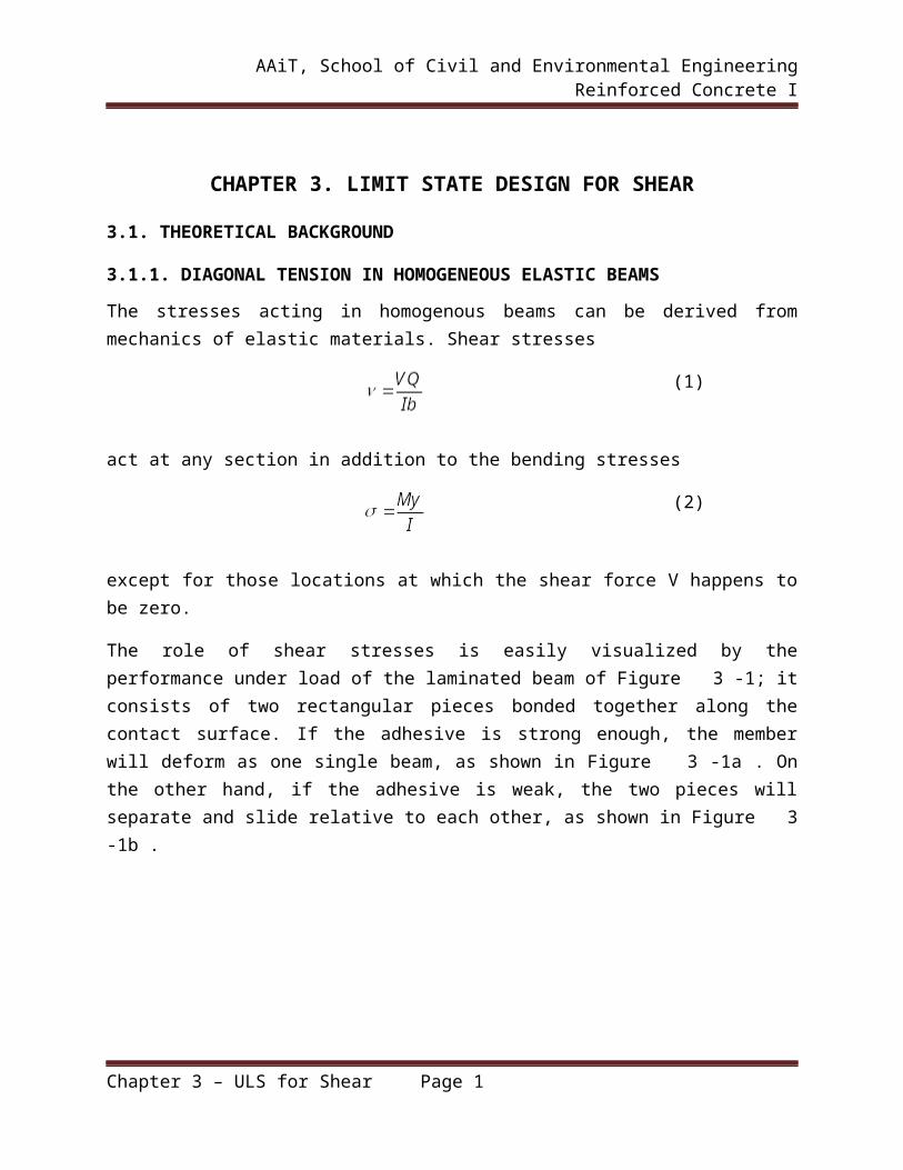
The role of shear stresses is easily visualized by the performance under load of the laminated beam of Figure 3-1; it consists of two rectangular pieces bonded together along the contact surface. If the adhesive is strong enough, the member will deform as one single beam, as shown in Figure 3-1a . On the other hand, if the adhesive is weak, the two pieces will separate and slide relative to each other, as shown in Figure 3-1b .
Chapter 3 – ULS for Shear Page 1

AAiT, School of Civil and Environmental Engineering Reinforced Concrete I
Figure 3-1 – Shear in homogeneous rectangular beams
Evidently, then, when the adhesive is effective, there are forces or stresses acting in it that prevent this sliding or shearing. These horizontal shear stresses are shown in Figure 3-1c as they act, separately, on the top and bottom pieces. The same stresses occur in horizontal planes in single-piece beams; they are different in intensity at different distances from the neutral axis.
Figure 3-1d shows a differential length of a single-piece rectangular beam acted upon by a shear force of magnitude V. Upward translation is prevented; i.e., vertical equilibrium is provided by the vertical shear stresses . Their average value is equal to the shear force divided by the cross-
sectional area , but their intensity varies over the depth of the section. The shear
stress is zero at the outer fibers and has a maximum of at the neutral axis, the variation being parabolic. If a small square element located at the neutral axis of such a beam is isolated as shown in Figure 3-2b, the vertical shear stresses on it, equal and opposite on the two faces for reasons of equilibrium, act as shown. However, if these were the only stresses present, the element would not be in equilibrium; it would spin. Therefore, on the two horizontal faces there exist equilibrating horizontal shear stresses of the same magnitude. That is, at any point within the beam, the horizontal shear stresses of Figure 3-2b are equal in magnitude to the vertical shear stresses of Figure 3-1d.
Figure 3-2 – Stress trajectories in homogeneous rectangular beam
Chapter 3 – ULS for Shear Page 2

AAiT, School of Civil and Environmental Engineering Reinforced Concrete I
It is proved in any strength-of-materials text that on an element cut at 450 these shear stresses combine in such a manner that their effect is as shown in Figure 3-2c. That is, the action of the two pairs of shear stresses on the vertical and horizontal faces is the same as that of two pairs of normal stresses, one tensile and one compressive, acting on the 450 faces and of numerical value equal to that of the shear stresses. If an element of the beam is considered that is located neither at the neutral axis nor at the outer edges, its vertical faces are subject not only to the shear stresses but also to the familiar bending stresses. The six stresses that now act on the element can again be combined into a pair of inclined compressive stresses and a pair of inclined tensile stresses that act at right angles to each other. They are known as principal stresses (Figure 3-2e).
Since the magnitudes of the shear stresses and the bending stresses change both along the beam and vertically with distance from the neutral axis, the inclinations as well as the magnitudes of the resulting principal stresses also vary from one place to another. Figure 3-2f shows the inclinations of these principal stresses for a uniformly loaded rectangular beam. That is, these stress trajectories are lines which, at any point, are drawn in that direction in which the particular principal stress, tension or compression, acts at that point. It is seen that at the neutral axis the principal stresses in a beam are always inclined at 450 to the axis. In the vicinity of the outer fibers they are horizontal near midspan.
An important point follows from this discussion. Tensile stresses, which are of particular concern in view of the low tensile strength of the concrete, are not confined to the horizontal bending stresses that are caused by bending alone. Tensile stresses of various inclinations and magnitudes, resulting from shear alone (at the neutral axis) or from the combined action of shear and bending, exist in all parts of a beam and can impair its integrity if not adequately provided for. It is for this reason that the inclined tensile stresses, known as diagonal tension, must be carefully considered in reinforced concrete design.
3.1.2. BEHAVIOR OF BEAMS FAILING IN SHEAR
3.1.2.1. Behavior of beams without web reinforcementThe forces transferring shear across an inclined crack in a beam without web reinforcements are illustrated in Figure 3-3.
Chapter 3 – ULS for Shear Page 3

AAiT, School of Civil and Environmental Engineering Reinforced Concrete I
Figure 3-3 – Internal forces in a cracked beam without web reinforcements
Shear is transferred across line A-B-C by , the shear in the compression zone, by , the vertical component of the shear transferred across the crack by interlock of the aggregate
particles on the two faces of the crack, and by , the dowel action of the longitudinal reinforcement. Immediately after inclined cracking, as much as 40 to 60 percent of the total shear
is carried by and together.
Considering D-E-F portion of the beam below the crack and summing moments about the
reinforcement at point E shows that and cause a moment about E that must be
equilibrated by a compression force . Horizontal force equilibrium on section A-B-D-E
shows that , and finally, and must equilibrate the external moment at this section.
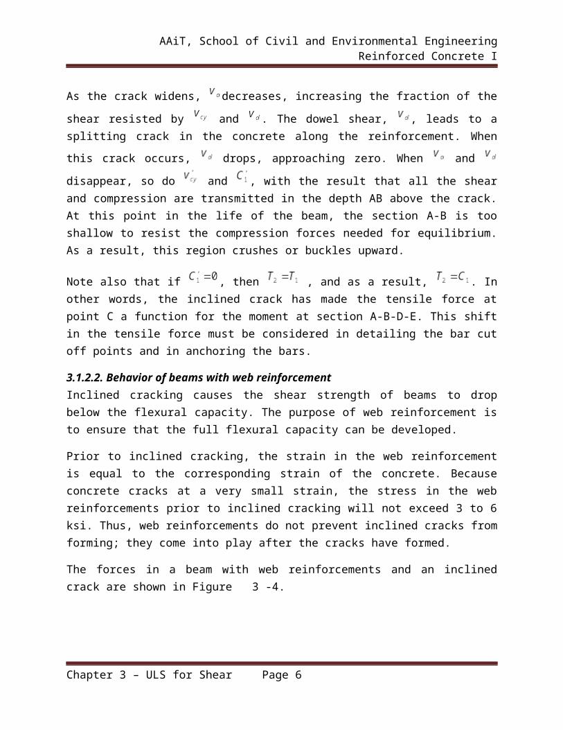
As the crack widens, decreases, increasing the fraction of the shear resisted by and .
The dowel shear, , leads to a splitting crack in the concrete along the reinforcement. When
this crack occurs, drops, approaching zero. When and disappear, so do and , with the result that all the shear and compression are transmitted in the depth AB above the crack. At this point in the life of the beam, the section A-B is too shallow to resist the compression forces needed for equilibrium. As a result, this region crushes or buckles upward.
Note also that if , then , and as a result, . In other words, the inclined crack has made the tensile force at point C a function for the moment at section A-B-D-E. This shift in the tensile force must be considered in detailing the bar cut off points and in anchoring the bars.
Chapter 3 – ULS for Shear Page 4

AAiT, School of Civil and Environmental Engineering Reinforced Concrete I
3.1.2.2. Behavior of beams with web reinforcementInclined cracking causes the shear strength of beams to drop below the flexural capacity. The purpose of web reinforcement is to ensure that the full flexural capacity can be developed.
Prior to inclined cracking, the strain in the web reinforcement is equal to the corresponding strain of the concrete. Because concrete cracks at a very small strain, the stress in the web reinforcements prior to inclined cracking will not exceed 3 to 6 ksi. Thus, web reinforcements do not prevent inclined cracks from forming; they come into play after the cracks have formed.
The forces in a beam with web reinforcements and an inclined crack are shown in Figure 3-4.
Figure 3-4 – Internal forces in a cracked beam with web reinforcements
The shear transferred by tension in the web reinforcements, , does not disappear when the
crack opens wider, so there will always be a compression force and a shear force acting
on the part of the beam below the crack. As a result, will be less than , the difference
depending on the amount of web reinforcement. The force will however, be larger than the
flexural tension based on the moment at C
The loading history of such a beam is shown qualitatively in Figure 3-5.
Chapter 3 – ULS for Shear Page 5
AAiT, School of Civil and Environmental Engineering Reinforced Concrete I
Figure 3-5 – Distribution of Internal shears in a beam with web reinforcement
The components of the internal shear resistance must equal the applied shear, indicated by the upper 450 line. Prior to flexural cracking, the entire shear is carried by the uncracked concrete.
Between flexural and inclined cracking, the external shear is resisted by , , and .
Eventually, the web reinforcements crossing the crack yield, and stays constant for higher applied shears. Once the web reinforcements yield, the inclined crack opens more rapidly. As the
inclined crack widens, decreases further, forcing and to increase at an accelerated rate, until either a splitting (dowel) failure occurs, the compression zone crushes due to combined shear and compression, or the web crushes.
Each of the components of this process except has a brittle load-deflection response. As a
result, it is difficult to quantify the contributions of , , and . In design, these are lumped
together as , referred to somewhat incorrectly as “the shear carried by the concrete.” Thus, the
nominal shear strength, , is assumed to be
(3)
Chapter 3 – ULS for Shear Page 6

AAiT, School of Civil and Environmental Engineering Reinforced Concrete I
3.1.3. FACTORS AFFECTING THE SHEAR STRENGTH OF BEAMS WITHOUT WEB REINFORCEMENT
Beams without web reinforcement will fail when inclined cracking occurs or shortly afterwards. For this reason, the shear capacity of such members is taken equal to the inclined cracking shear. The inclined cracking load of a beam is affected by five principal variables, some included in design equations and others not.
1. Tensile strength of concrete
The inclined cracking load is a function of the tensile strength of the concrete, . The stress state in the web of the beam involves biaxial principal tension and compression stresses. A similar biaxial state of stress exists in a split-cylinder tension test, and the inclined cracking load is frequently related to the strength from such a test. As discussed earlier, the flexural cracking that precedes the inclined cracking disrupts the elastic-stress field to such an extent that inclined
cracking occurs at a principal tensile stress roughly half of for the uncracked section.
2. Longitudinal reinforcement ratio,
When the steel ratio, , is small, flexural cracks extend higher into the beam and open wider
than would be the case for large values of . And increase in crack width causes a decrease in
the maximum values of the components of shear, and , that are transferred across the inclined cracks by dowel action or by shear stresses on the crack surfaces. Eventually, the resistance along the crack drops below that required to resist the loads, and the beam fails suddenly in shear.
3. Shear span to depth ratio, a/d
The shear span to depth ratio ,a/d or MV/d, affects the inclined cracking shears and ultimate shears of portions of members with a/d less than 2.
4. Lightweight aggregate concrete
Lightweight aggregate concrete has a lower tensile strength than normal weight concrete for a given concrete compressive strength. Because the shear strength of a concrete member without shear reinforcement is directly related to the tensile strength of a concrete, equations for shear capacity must be modified for members constructed with light weight concrete.
5. Size of beam
An increase in the overall depth of a beam with very little (or no) web reinforcement results in a
decrease in the shear at failure for a given , , and a/d. The width of an inclined crack
Chapter 3 – ULS for Shear Page 7

AAiT, School of Civil and Environmental Engineering Reinforced Concrete I
depends on the product of the strain in the reinforcement crossing the crack and the spacing of the cracks. With increasing beam depth, the crack spacings and the crack widths tend to increase. This leads to a reduction in the maximum shear stress that can be transferred across the crack by aggregate interlock. An unstable situation develops when the shear stresses transferred across the crack exceeds the shear strength. When this occurs, the faces of the crack slip, one relative to the other.
6. Axial forces
Axial tensile forces tend to decrease the inclined cracking load, while axial compressive forces tend to increase it. As the axial compressive force is increased, the onset of flexural cracking is delayed, and the flexural cracks do not penetrate as far into the beam. Axial tension forces directly increase the tension stress, and hence the strain, in the longitudinal reinforcement. This causes an increase in the inclined crack width, which, in turn, results in a decrease in the maximum shear tension stress that can be transmitted across the crack. This reduces the shear failure load.
A similar increase is observed in prestressed concrete beams. The compression due to prestressing reduces the longitudinal strain, leading to a higher failure load.
7. Coarse aggregate size
As the size (diameter) of the coarse aggregate increases, the roughness of the crack surfaces increases, allowing higher shear stresses to be transferred across the cracks. In high strength concrete beams and some light weight concrete beams, the cracks penetrate pieces of the aggregate rather than going around them, resulting in a smoother crack surface. This decrease in
the shear transferred by aggregate interlock along the cracks reduces .
3.2. DESIGN OF BEAMS FOR VERTICAL SHEAR ACCORDING TO EN 1992-1-1-2004
For the verification of the shear resistance the following symbols are defined:
is the design shear resistance of the member without shear reinforcementis the design value of the shear force which can be sustained by the yielding shear reinforcementis the design value of the maximum shear force which can be sustained by the member, limited by crushing of the compression struts.
The shear resistance of a member with shear reinforcement is equal to:
(4)
In regions of the member where , no calculated shear reinforcement is necessary. is the design shear force in the section considered resulting from the external loading.
Chapter 3 – ULS for Shear Page 8

AAiT, School of Civil and Environmental Engineering Reinforced Concrete I
In regions where , sufficient shear reinforcement should be provided in order that
The design shear force should not exceed the permitted maximum value , anywhere in the member.
For members subject to predominantly uniformly distributed loading, the design shear force need not be checked at a distance less that d from the face of the support. Any shear reinforcement required should continue to the support. In addition it should be verified that the shear at the
support does not exceed
3.2.1. MEMBERS NOT REQUIRING DESIGN SHEAR REINFORCEMENT
The design value for the shear resistance is given by:
(5)
with a minimum of
(6)
where:
is in MPa
with d in mm
(7)
(8)
is the area of the tensile reinforcement, which extends beyond the section consideredis the smallest width of the cross-section in the tensile area (mm)
[MPa]is the axial force in the cross-section due to loading or prestressing in newtons (
for compression). The influence of imposed deformations on may be ignored.Is the area of concrete cross section [mm2]is in newtons
Chapter 3 – ULS for Shear Page 9
AAiT, School of Civil and Environmental Engineering Reinforced Concrete I
The values of , and for use in a country may be found in its National Annex. The
recommended value for is , that for is and that for is 0.15.
The design of members with shear reinforcement is based on a truss model. The angle θ should be limited. The limiting values of for use in a country may be found in its National Annex. The recommended limits are
3.2.2. MEMBERS REQUIRING DESIGN SHEAR REINFORCEMENT
For members with vertical shear reinforcement, the shear resistance, is the smaller value of :
(9)
and
(10)
Where
is the cross-sectional area of the shear reinforcements is the spacing of the stirrups
is the design yield strength of the shear reinforcementfollows from the expression below
For reinforced and prestressed members, if the design stress of the shear reinforcement is below
80% of the characteristic yield stress , may be taken as:
for MPa (11)
for MPa (12)
The value of for use in a Country may be found in its National Annex. The recommended value is 1 for non-prestressed structures.
The maximum effective cross-sectional area of the shear reinforcement is given by:
(13)
For members with inclined shear reinforcement, the shear resistance is the smaller value of
(14)
And
Chapter 3 – ULS for Shear Page 10
AAiT, School of Civil and Environmental Engineering Reinforced Concrete I
(15)
The maximum effective shear reinforcement follows from:
(16)
3.2.3. ADDITIONAL TENSILE FORCE IN LONGITUDINAL REINFORCEMENT
The longitudinal tension reinforcement should be able to resist the additional tensile force caused by shear.
The additional tensile force, , in the longitudinal reinforcement due to shear may be calculated from:
(17)
should be taken not greater than
3.2.4. MINIMUM AREA AND MAXIMUM SPACING OF SHEAR REINFORCEMENT
The ratio of shear reinforcement is given by
(18)
where:
is the shear reinforcement ratio
should not be less than is the area of shear reinforcement within length s
s is the spacing of the shear reinforcement measured along the longitudinal axis of the memberis the breadth of the web of the memberis the angle between shear reinforcement and the longitudinal axis
When, on the basis of the design shear calculation, no shear reinforcement is required, minimum shear reinforcement should nevertheless be provided. The minimum shear reinforcement may be omitted in members such as slabs (solid, ribbed or hollow core slabs) where transverse redistribution of loads is possible. Minimum reinforcement may also be omitted in members of minor importance which do not contribute significantly to the overall resistance and stability of the structure.
The value of for beams for use in a Country may be found in its National Annex. The
recommended value is
Chapter 3 – ULS for Shear Page 11
AAiT, School of Civil and Environmental Engineering Reinforced Concrete I
The maximum longitudinal spacing between shear assemblies should not exceed .
The value of for use in a country may be found in its National Annex. The recommended
value is
where is the inclination of the shear reinforcement to the longitudinal axis of the beam.
3.2.5. PROCEDURE FOR DESIGN
Step 1: Determine maximum applied shear force at support,
Step 2: Determine with
Step 3:If , go to step 6 and calculate required shear reinforcement
Step 4:If calculate required strut angle:
Step 5: If is less than 1, re-size element, otherwise
Step 6: Calculate amount of shear reinforcement required
Step 7: Check min shear reinforcement and maximum spacing
3.3. DEVELOPMENT, ANCHORAGE, AND SPLICING OF REINFORCEMENT
3.3.1. INTRODUCTION
‘Bond’ in reinforced concrete refers to the adhesion between the reinforcing steel and the surrounding concrete. It is this bond which is responsible for the transfer of axial force from a reinforcing bar to the surrounding concrete, thereby providing strain compatibility and ‘composite action’ of concrete and steel. If this bond is inadequate, ‘slipping’ of the reinforcing bar will occur, destroying full ‘composite action’. Hence, the fundamental assumption of the theory of flexure, viz. plane sections remain plane even after bending, becomes valid in reinforced concrete only if the mechanism of bond is fully effective.
It is through the action of bond resistance that the axial stress (tensile or compressive) in a reinforcing bar can undergo variation from point to point along its length. This is required to accommodate the variation in bending moment along the length of the flexural member. Had the bond been absent, the stress at all points on a straight bar would be constant, as in a string or a straight cable.
Mechanisms of Bond Resistance
Chapter 3 – ULS for Shear Page 12
AAiT, School of Civil and Environmental Engineering Reinforced Concrete I
Bond resistance in reinforced concrete is achieved through the following mechanisms:
1. Chemical adhesion — due to a gum-like property in the products of hydration (formed during the making of concrete).
2. Frictional resistance — due to the surface roughness of the reinforcement and the grip exerted by the concrete shrinkage.
3. Mechanical interlock — due to the surface protrusions or ‘ribs’ (oriented transversely to the bar axis) provided in deformed bars.
Evidently, the resistance due to ‘mechanical interlock’ (which is considerable) is not available when plain bars are used. For this reason, many codes prohibit the use of plain bars in reinforced concrete — except for lateral spirals, and for stirrups and ties smaller than 10 mm in diameter.
Bond Stress
Bond resistance is achieved by the development of tangential (shear) stress components along the interface (contact surface) between the reinforcing bar and the surrounding concrete. The stress so developed at the interface is called bond stress, and is expressed in terms of the tangential force per unit nominal surface area of the reinforcing bar.
Two Types of Bond
There are two types of loading situations which induce bond stresses, and accordingly ‘bond’ is characterized as:
1. Flexural bond; 2. Anchorage bond or development bond.
Chapter 3 – ULS for Shear Page 13

AAiT, School of Civil and Environmental Engineering Reinforced Concrete I
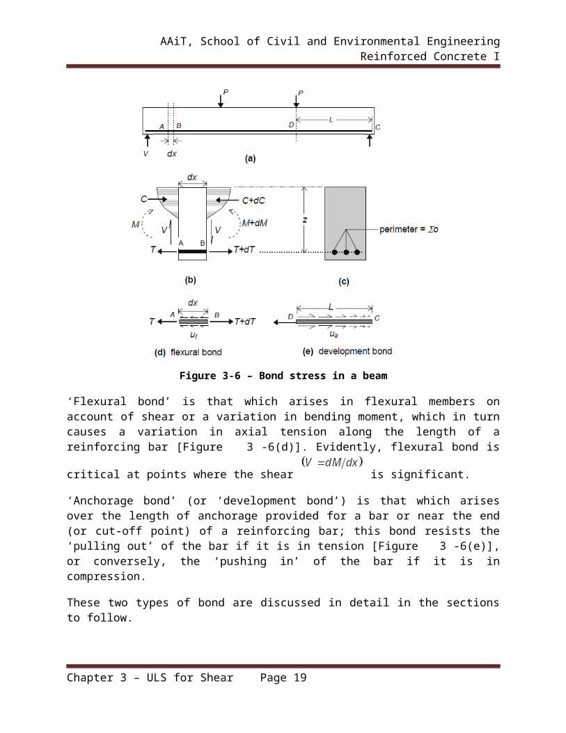
Figure 3-6 – Bond stress in a beam
‘Flexural bond’ is that which arises in flexural members on account of shear or a variation in bending moment, which in turn causes a variation in axial tension along the length of a reinforcing bar [Figure 3-6(d)]. Evidently, flexural bond is critical at points where the shear
is significant.
‘Anchorage bond’ (or ‘development bond’) is that which arises over the length of anchorage provided for a bar or near the end (or cut-off point) of a reinforcing bar; this bond resists the ‘pulling out’ of the bar if it is in tension [Figure 3-6(e)], or conversely, the ‘pushing in’ of the bar if it is in compression.
These two types of bond are discussed in detail in the sections to follow.
3.3.2. FLEXURAL BOND
As mentioned earlier, variation in tension along the length of a reinforcing bar, owing to varying bending moment, is made possible through flexural bond. The flexural stresses at two adjacent sections of a beam, dx apart, subjected to a differential moment dM, is depicted in Figure 3-6(b). With the usual assumptions made in flexural design, the differential tension dT in the tension steel over the length dx is given by
( 3-12)
Chapter 3 – ULS for Shear Page 14
AAiT, School of Civil and Environmental Engineering Reinforced Concrete I
where z is the lever arm.
This unbalanced bar force is transferred to the surrounding concrete by means of ‘flexural bond’
developed along the interface. Assuming the flexural (local) bond stress to be uniformly distributed over the interface in the elemental length dx, equilibrium of forces gives:
( 3-13)
where Σo is the total perimeter of the bars at the beam section under consideration [Figure 3-6(c)].
From the above equation, it is evident that the bond stress is directly proportional to the change in the bar force. Combining the above two equations, the following expression for the local bond
stress is obtained:( 3-14)
Alternatively, in terms of the transverse shear force at the section ,( 3-15)
It follows that flexural bond stress is high at locations of high shear, and that this bond stress can be effectively reduced by providing an increased number of bars of smaller diameter bars (to give the same equivalent Ast).
It may be noted that the actual bond stress will be influenced by flexural cracking, local slip, splitting and other secondary effects — which are not accounted for in the above equation.
In particular, flexural cracking has a major influence in governing the magnitude and distribution of local bond stresses.
Effect of Flexural Cracking on Flexural Bond Stress
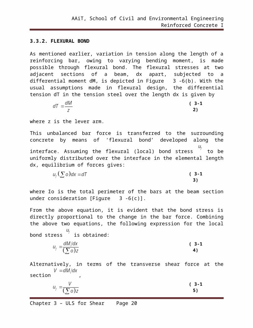
From the above equation, it appears that the flexural (local) bond stress has a variation that is similar to and governed by the variation of the transverse shear force V. In fact, it would appear that in regions of constant moment, where shear is zero, there would be no bond stress developed at all. However, this is not true. The tensile force T in the reinforcement varies between flexural crack locations, even in regions of constant moment, as indicated in Figure 3-7. At the flexural crack location, the tension is carried by the reinforcement alone, whereas in between the cracks, concrete carries some tension and thereby partially relieves the tension in the steel bars. As local bond stress is proportional to the rate of change of bar force, local bond stresses do develop in such situations.
Chapter 3 – ULS for Shear Page 15

AAiT, School of Civil and Environmental Engineering Reinforced Concrete I
Figure 3-7 – Effect of flexural cracks on flexural bond stress in constant moment region
The bond stresses follow a distribution somewhat like that shown in Figure 3-7(c), with the direction of the bond stress reversing between the cracks. The net bond force between the cracks will, of course, be zero in a region of constant moment. When the moment varies between the flexural cracks, the bond stress distribution will differ from that shown in Figure 3-7(c), such that the net bond force is equal to the unbalanced tension in the bars between the cracks.
Beam tests show that longitudinal splitting cracks tend to get initiated near the flexural crack locations where the local peak bond stresses can be high. The use of large diameter bars particularly renders the beam vulnerable to splitting and/or local slip.
Finally, it may be noted that flexural cracks are generally not present in the compression zone. For this reason, flexural bond is less critical in a compression bar, compared to a tension bar with an identical axial force.
3.3.3. ANCHORAGE (DEVELOPMENT) BOND
As mentioned earlier, anchorage bond or development bond is the bond developed near the extreme end (or cut-off point) of a bar subjected to tension (or compression). This situation is depicted in the cantilever beam of Figure 3-8, where it is seen that the tensile stress in the bar
Chapter 3 – ULS for Shear Page 16
AAiT, School of Civil and Environmental Engineering Reinforced Concrete I
segment varies from a maximum at the continuous end D to practically zero at the discontinuous end C.
Figure 3-8 – Anchorage bond stress
The bending moment, and hence the tensile stress , are maximum at the section at D.
Evidently, if a stress is to be developed in the bar at D, the bar should not be terminated at D, but has to be extended (‘anchored’) into the column by a certain length CD. At the discontinuous end C of the bar, the stress is zero. The difference in force between C and D is transferred to the surrounding concrete through anchorage bond. The probable variation of the anchorage bond
stress is as shown in Figure 3-8(b) — with a maximum value at D and zero at C.
An expression for an average bond stress can be derived by assuming a uniform bond stress
distribution over the length L of the bar of diameter [Figure 3-8(c)], and considering equilibrium of forces as given below:
( 3-16)
This bond stress may be viewed as the average bond stress generated over a length L in order to
develop a maximum tensile (or compressive) stress at a critical section; hence, this type of
Chapter 3 – ULS for Shear Page 17

AAiT, School of Civil and Environmental Engineering Reinforced Concrete I
bond is referred to as ‘development bond’. Alternatively this bond may be viewed as that required to provide anchorage for a critically stressed bar; hence, it is also referred to as ‘anchorage bond’.
3.3.4. BOND FAILURE AND BOND STRENGTH
Bond Failure Mechanisms
The mechanisms that initiate bond failure may be any one or combination of the following:
break-up of adhesion between the bar and the concrete; Longitudinal splitting of the concrete around the bar; Crushing of the concrete in front of the bar ribs (in deformed bars); and Shearing of the concrete keyed between the ribs along a cylindrical surface surrounding
the ribs (in deformed bars).
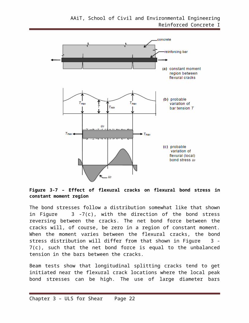
The most common type of bond failure mechanism is the pulling loose of the reinforcement bar, following the longitudinal splitting of the concrete along the bar embedment [Figure 3-9]. Occasionally, failure occurs with the bar pulling out of the concrete, leaving a circular hole without causing extensive splitting of the concrete. Such a failure may occur with plain smooth bars placed with large cover, and with very small diameter deformed bars (wires) having large concrete cover. However, with deformed bars and with the normal cover provided in ordinary beams, bond failure is usually a result of longitudinal splitting. In the case of ribbed bars, the bearing pressure between the rib and the concrete is inclined to the bar axis [Figure 3-9(b)]. This introduces radial forces in the concrete (‘wedging action’), causing circumferential tensile stresses in the concrete surrounding the bar (similar to the stresses in a pipe subjected to internal pressure) and tending to split the concrete along the weakest plane. Splitting occurs along the thinnest surrounding concrete section, and the direction of the splitting crack (‘bottom splitting’ or ‘side splitting’) depends on the relative values of the bottom cover, side cover and bar spacing as shown in Figure 3-9(b).
Chapter 3 – ULS for Shear Page 18
AAiT, School of Civil and Environmental Engineering Reinforced Concrete I
Figure 3-9 – Typical bond splitting crack patterns
Splitting cracks usually appear on the surface as extensions of flexural or diagonal tension cracks in flexural members, beginning in regions of high local bond stress . With increased loads, these cracks propagate gradually along the length of embedment (‘longitudinal splitting’) with local splitting at regions of high local bond stress and associated redistribution of bond stresses.]. The presence of stirrups offers resistance to the propagation of continuous longitudinal splitting cracks [Figure 3-10]. However, in beams without stirrups, the failure due to bond can occur early and suddenly, as the longitudinal split runs through to the end of the bar without the resistance offered by the stirrups.
Figure 3-10 – Stirrups resisting tensile forces due to bond
Chapter 3 – ULS for Shear Page 19
AAiT, School of Civil and Environmental Engineering Reinforced Concrete I
Bond Tests
Bond strength is usually ascertained by means of pull out tests or some sort of beam tests. The typical ‘pull out’ test is shown schematically in Figure 3-11(a). A bar embedded in a concrete cylinder or prism is pulled until failure occurs by splitting, excessive slip or pull-out. The
nominal bond strength is computed as , where P is the pull at failure, the bar diameter and L the length of embedment. It may be noted, however, that factors such as cracking (flexural or diagonal tension) and dowel forces, which lower the bond resistance of a flexural member, are not present in a concentric pull out test. Moreover, the concrete in the test specimen is subjected to a state of compression (and not tension), and the friction at the bearing on the concrete offers some restraint against splitting. Hence, the bond conditions in a pull out test do not ideally represent those in a flexural member.
Figure 3-11 – Bond tests
Chapter 3 – ULS for Shear Page 20

AAiT, School of Civil and Environmental Engineering Reinforced Concrete I
Of the several types of beam tests developed to simulate the actual bond conditions, one test set-up is shown in Figure 3-11(b) . The bond strength measured from such a test, using the same
expression as for a pull-out test, is bound to give a lesser (and more accurate) measure of the bond strength than the pull out strength. However, the pull out test is easier to perform, and for this reason, more commonly performed.
From the results of such bond tests, the ‘design bond stress’ (permissible average anchorage bond stress) is arrived at - for various grades of concrete. Tests indicate that bond strength varies
proportionately with for small diameter bars and for large diameter deformed bars
Factors Influencing Bond Strength
Bond strength is influenced by several factors, some of which have already been mentioned. In general, bond strength is enhanced when the following measures are adopted:
deformed (ribbed) bars are used instead of plain bars; smaller bar diameters are used; higher grade of concrete (improved tensile strength) is used; increased cover is provided around each bar; increased length of embedment, bends and /or hooks are provided; mechanical anchorages are employed; stirrups with increased area, reduced spacing and/or higher grade of steel are used; termination of longitudinal reinforcement in tension zones is avoided; any measure that will increase the confinement of the concrete around the bar is
employed.
Another factor which influences bond strength in a beam is the depth of fresh concrete below the bar during casting. Water and air inevitably rise towards the top of the concrete mass and tend to get trapped beneath the horizontal reinforcement, thereby weakening the bond at the underside of these bars. For this reason, codes specify a lower bond resistance for the top reinforcement in a beam.
3.3.5. SPLICING OF REINFORCEMENT
Splices are required when bars placed short of their required length (due to non-availability of longer bars) need to be extended. Splices are also required when the bar diameter has to be changed along the length (as is sometimes done in columns). The purpose of ‘splicing’ is to transfer effectively the axial force from the terminating bar to the connecting (continuing) bar with the same line of action at the junction. This invariably introduces stress concentrations in the surrounding concrete. These effects should be minimized by:
using proper splicing techniques; keeping the splice locations away from sections with high flexural/shear stresses; and Staggering the locations of splicing in the individual bars of a group (as, typically in a
column).
Chapter 3 – ULS for Shear Page 21
AAiT, School of Civil and Environmental Engineering Reinforced Concrete I
Splicing is generally done in one of the following three ways:
1. Lapping of bars (lap splice) 2. Welding of bars (welded splice) 3. Mechanical connections.
3.4. PROVISIONS OF EN -1992-1-1-2004 ON DEVELOPMENT, ANCHORAGE AND SPLICING OF REINFORCEMENT
3.4.1. ANCHORAGE OF LONGITUDINAL REINFORCEMENT
Ultimate bond stress
The ultimate bond resistance shall be sufficient to prevent bond failure and the design value of
the ultimate bond stress, , for ribbed bars may be taken as:
( 3-6)
Where:
is the design value of concrete tensile strengthis a coefficient related to the quality of the bond condition and the position of the bar during concreting
when ‘good’ conditions are obtained and
for all other cases and for bars in structural elements built with slip-forms, unless it can be shown that ‘good’ bond conditions existis related to the bar diameter:
for
Figure 3-12 – Description of bond conditions
Chapter 3 – ULS for Shear Page 22

AAiT, School of Civil and Environmental Engineering Reinforced Concrete I
Basic anchorage length
The calculation of the required anchorage length shall take into consideration the type of steel and bond properties of the bars.
The basic required anchorage length, , for anchoring the force in a bar assuming
constant bond stress equal to follows from:
( 3-7)
where is the design stress of the bar at the position from where the anchorage is measured from at the ultimate limit state.
Design anchorage length
The design anchorage length, , :
Where α1, α2, α3, α4 and α5 are coefficients given in Table 1:
is for the effect of the form of the bars assuming adequate coveris for the effect of concrete minimum cover (see Figure 3-13)is for the effect of confinement by transverse reinforcement
is for the influence of one or more welded transverse bars along the design
anchorage length is for the effect of the pressure transverse to the plane of splitting along the design anchorage length
The product
is the minimum anchorage length if no other limitation is applied:
- For anchorages in tension:
- For anchorages in compression:
Chapter 3 – ULS for Shear Page 23

AAiT, School of Civil and Environmental Engineering Reinforced Concrete I
Figure 3-13 – Values of Cd for beams and slabs
Table 1 – Values of α coefficients
Figure 3-14 – Values of K for beams and slabs
Chapter 3 – ULS for Shear Page 24

AAiT, School of Civil and Environmental Engineering Reinforced Concrete I
3.4.2. LAPS
The detailing of laps between bars shall be such that:
The transmission of the forces from one bar to the next is assured Spalling of the concrete in the neighborhood of the joints does not occur; Large cracks which affect the performance of the structure do not occur
Laps:
Between bars should normally be staggered and not located in areas of high stress. At any one section should normally be arranged symmetrically
The arrangement of lapped bars should comply with Figure 3-15
The clear transverse distance between two lapped bars should not be greater than or 50 mm, otherwise the lap length should be increased by a length equal to the clear space
where it exceeds or 50 mm; The longitudinal distance between two adjacent laps should not be less than 0.3 times the
lap length, ; In case of adjacent laps, the clear distance between adjacent bars should not be less than
or 20 mm.
Figure 3-15 – Adjacent laps
Lap length
The design lap length is:
( 3-8)
Where:
Chapter 3 – ULS for Shear Page 25
AAiT, School of Civil and Environmental Engineering Reinforced Concrete I
Values of may be taken from Table 1; however, for the calculation of ,
should be taken as , with area of one lapped bar.
but not exceeding 1.5, where is the percentage of reinforcement lapped
within from the center of the lap length considered (see Figure ). Values of are given in the table below.
Table 2 – Values of the coefficient
Figure 3-16 – Percentage of lapped bars in one section
Transverse reinforcement in the lap zone
a) Transverse reinforcement for bars in tension
Transverse reinforcement is required in the lap zone to resist transverse tension forces.
Where the diameter, , of the lapped bars is less than 20 mm, or the percentage of lapped bars in any one section is less than 25%, then any transverse reinforcement or links necessary for other reasons may be assumed sufficient for the transverse tensile forces without further justification.
Where the diameter, , of the lapped bars is greater than or equal to 20 mm, the transverse
reinforcement should have a total area, (sum of all legs parallel to the layer of the spliced
Chapter 3 – ULS for Shear Page 26

AAiT, School of Civil and Environmental Engineering Reinforced Concrete I
reinforcement) of not less than the area of one lapped bar , assuming that the lapped bar is fully stressed. The transverse bar should be placed perpendicular to the direction of the lapped reinforcement and between that and the surface of the concrete.
If more than 50% of the reinforcement is lapped at one point and the distance, a, between
adjacent laps at a section is (see Figure 3-15) transverse bars should be formed by links or U bars anchored into the body of the section.
The transverse reinforcement should be positioned at the outer sections of the lap as shown in Figure 3-17.
b) Transverse reinforcement for bars permanently in compression
In addition to the rules for bars in tension one bar of the transverse reinforcement should be
placed outside each end of the lap length and within of the ends of the lap length (Figure 3-17)
Figure 3-17 – Transverse reinforcement for lapped splices
Chapter 3 – ULS for Shear Page 27