aalborg universitet high order voltage and current
TRANSCRIPT

Aalborg Universitet
High Order Voltage and Current Harmonic Mitigation Using the Modular MultilevelConverter STATCOM
Kontos, Epameinondas; Tsolaridis, Georgios; Teodorescu, Remus; Bauer, Pavol
Published in:IEEE Access
DOI (link to publication from Publisher):10.1109/ACCESS.2017.2749119
Publication date:2017
Document VersionPublisher's PDF, also known as Version of record
Link to publication from Aalborg University
Citation for published version (APA):Kontos, E., Tsolaridis, G., Teodorescu, R., & Bauer, P. (2017). High Order Voltage and Current HarmonicMitigation Using the Modular Multilevel Converter STATCOM. IEEE Access, 5, 16684-16692. [8025588].https://doi.org/10.1109/ACCESS.2017.2749119
General rightsCopyright and moral rights for the publications made accessible in the public portal are retained by the authors and/or other copyright ownersand it is a condition of accessing publications that users recognise and abide by the legal requirements associated with these rights.
? Users may download and print one copy of any publication from the public portal for the purpose of private study or research. ? You may not further distribute the material or use it for any profit-making activity or commercial gain ? You may freely distribute the URL identifying the publication in the public portal ?
Take down policyIf you believe that this document breaches copyright please contact us at [email protected] providing details, and we will remove access tothe work immediately and investigate your claim.
SPECIAL SECTION ON POWER QUALITY AND HARMONICS ISSUESOF FUTURE AND SMART GRIDS
Received July 28, 2017, accepted August 30, 2017, date of publication September 4, 2017, date of current version September 19, 2017.
Digital Object Identifier 10.1109/ACCESS.2017.2749119
High Order Voltage and Current HarmonicMitigation Using the Modular MultilevelConverter STATCOMEPAMEINONDAS KONTOS1, (Member, IEEE), GEORGIOS TSOLARIDIS2,REMUS TEODORESCU2, (Fellow, IEEE), AND PAVOL BAUER1, (Senior Member, IEEE)1Delft University of Technology, 2628 CD Delft, The Netherlands2Aalborg University, 9100 Aalborg, Denmark
Corresponding author: Epameinondas Kontos ([email protected])
ABSTRACT Due to the increase of power electronic-based loads, the maintenance of high power qualityposes a challenge in modern power systems. To limit the total harmonic distortion in the line voltage andcurrents at the point of the common coupling (PCC), active power filters are commonly employed. Thispaper investigates the use of themultilevel modular converter (MMC) for harmonicsmitigation due to its highbandwidth compared with conventional converters. A selective harmonics detection method and a harmonicscontroller are implemented, while the output current controller of the MMC is tuned to selectively inject thenecessary harmonic currents. Unlike previous studies, focus is laid on the experimental verification of theactive filtering capability of the MMC. For this reason an MMC-based double-star STATCOM is developedand tested for two representative case studies, i.e., for grid currents and PCC voltage harmonics. The resultsverify the capability of the MMC to mitigate harmonics up to the thirteenth order, while maintaining a loweffective switching frequency and thus, low switching losses.
INDEX TERMS Active power filters, harmonics, MMC, STATCOM.
I. INTRODUCTIONAmajor problem inmodern power systems is the reduction ofpower quality due to the introduction of harmonic content byvarious power electronic-based loads. The current harmonicscan cause voltage fluctuations and malfunction of electronicequipment. One of the biggest challenges of the grid operatorsis to keep the power quality standards high, by limiting theline voltage and currents’ Total Harmonic Distortion (THD)at the Point of Common Coupling (PCC) [1].
The techniques for harmonic elimination can be dividedinto three main categories, i.e. passive, active and hybridfiltering [2]. The use of Passive Power Filters (PPF) is well-established, especially for low voltage systems. In this case,inductors and capacitors are tuned to mitigate specific har-monic content thereby, improving power quality. However,in medium/high voltage systems, the size and cost of PFFsincreases, while several unwanted side effects appear, suchas ringing transient response and resonance [3], [4]. More-over, PPFs have limitations such as difficulty in tuning, fixedfilter frequency and resonance due to matching with lineimpedance [5]. As a result, active filtering topologies areinvestigated [4].
Active and hybrid filters are commonly used in industrialapplications. An Active Power Filter (APF) is a power elec-tronic converter designed to a fraction of the load power,which is used for harmonic filtering and is connected closeto the non-linear load or at the PCC [6]. With the recentimprovements in the ratings and the switching behavior ofpower semiconductor devices, APFs are increasingly used toovercome the PPF drawbacks [5]. APFs are able to detect theload current harmonics and generate a compensating currentusing an output current controller [6].
Voltage-Source Converters (VSCs) are commonly usedfor harmonic mitigation [7]. Moreover, conventional mul-tilevel converter topologies such as Flying Capacitor Con-verter (FCC), three-level diode Neutral Point Clamped (NPC)converter and Cascaded H-Bridge converter (CHB) are usedfor power quality improvement in different applications.In the last decade, Modular Multilevel Converter (MMC)has been introduced for high voltage (HVDC), as well asfor medium voltage (STATCOM) applications. Apart fromthe advantages over the conventional topologies due to itsmodularity and scalability, the inclusion of many submod-ules results in a low effective switching frequency of the
166842169-3536 2017 IEEE. Translations and content mining are permitted for academic research only.
Personal use is also permitted, but republication/redistribution requires IEEE permission.See http://www.ieee.org/publications_standards/publications/rights/index.html for more information.
VOLUME 5, 2017
E. Kontos et al.: High Order Voltage and Current Harmonic Mitigation Using the MMC STATCOM
submodule power semiconductor devices, while maintaininga high switching frequency of the converter, and therefore,in an increased effective control bandwidth without compro-mising the converter’s efficiency. Using the available band-width in the MMC, it is possible to increase the accuracy ofharmonic elimination in lower order harmonics, while at thesame time being able to control higher order harmonics [8].The aforementioned advantages make the MMC promisingfor APF applications [9].
Different control strategies can be used for the currentand voltage harmonics compensation to improve the THD.These control strategies are based on detection of harmon-ics through measurement of either the load and convertercurrents or the grid voltage and current. Several open-loopcontrol schemes using grid voltage feed-forward have beenproposed to compensate the grid harmonic voltage [10]–[13],but they are not sufficient to suppress line current harmonicsdue to dead time effect [14]. Feed-forward compensationfor line current harmonics can also be implemented by firstextracting the current harmonic components using high passfilters in the stationary reference frame. At medium voltageand low current, there is little margin for error and thus, feed-forward compensation schemes are not preferred, whereasfeedback-based approaches are recommended [14].
When proportional-resonant (PR) controllers orPI-resonant controllers are used for harmonic compensation,two possible implementations arise. The first is to use asingle frame for each nth harmonic rotating at frequency nω.The second is to use nested frames. More specifically, twocontrollers in two frames rotating at (n+ 1)ω and −(n+ 1)ωcan be implemented in the main synchronous frame [10].Both implementations are equivalent in terms of computa-tional burden [10] and thus, high bandwidth is necessary forthe current control loops in order to have satisfactory resultsin the elimination of steady-state errors [14]. Additionally,predictive harmonic control has been proposed and validatedin [15]. However, the controller design is demanding in termsof tuning and depends on the application. Moreover, a non-optimized design can increase the computational burden andthe hardware utilization significantly.
An investigation of the performance of the MMC in themitigation of harmonics can be found in [16] and [17].These studies consider a hybrid structure of the MMC with‘fundamental’ cells, which are intended to compensate thefundamental input power factor and the ‘harmonic’ cells,whose number depends on the number of harmonics that needto be compensated. A PI controller and a static decouplerare used to determine the modulation of each cell, whichis used to cancel a specific load current harmonic. How-ever, in this case the MMC design becomes more complexwithout a significant benefit in efficiency, while redundantsubmodules switching at high frequencies are used, whichcould unnecessarily increase the cost and volume of thesystem. More studies have also investigated the use of MMCas APF [8], [9], [18]. However, these studies consider onlyaverage simulation models without experimental validation,
which in this case is essential, since simulation studies neglectthe non-linearities and delays introduced in the real system,as well as quantization errors due to the ADC interface andaccuracy limitations of the sensors.
Recent grid codes require the mitigation of high orderharmonics of current and voltage, which cannot be eas-ily accomplished with conventional converters [19], [20].This paper proves that even a 5-level MMC-based APF isable to mitigate such high harmonics without increasing itsswitching frequency and thus, its losses. Contrary to existingliterature on MMC applications as APF, this is achievedthrough extensive experimental results, which are obtainedusing a developed MMC prototype in a laboratory set-up fortwo representative case studies, i.e. for current and voltageharmonics mitigation. More specifically, in this study theperformance of the MMC STATCOM topology is evaluatedin the mitigation of voltage and current harmonics at the PCCup to the 13th order and the results on the THD and individualharmonic components are compared to limits as specified byNational Grid data [21]. To achieve this, a simple harmonicsdetection method is applied using Low-Pass Filters (LFP) indq-frame. The voltage and current harmonics are controlledfirst using PI controllers, which generate the reference forthe output current harmonic components and subsequently,PR controllers are used in parallel to the fundamental outputcurrent control loop of the MMC.
The paper is structured as follows: Section II introduces thecontrol strategy used for the current and voltage harmonicsdetection and elimination and the tuning of the required filtersand controllers is thoroughly explained. In Section III thelaboratory set-up of the MMC STATCOM is presented. Thecase study and the obtained results for the current harmon-ics are presented in Section IV, while Section V presentsexperimental results for the voltage harmonics elimination.Section VI summarizes the main conclusions drawn from theanalysis.
II. HARMONIC MITIGATION CONTROL SCHEMEIn this study an MMC-based STATCOM is used inDouble-Star (DS) configuration with half-bridge submod-ules, as shown in Fig. 1. This configuration has been exten-sively studied [22], [23] and has been shown to be superioragainst the topology with delta-connected Full-Bridge (FB)submodules (FB-D), especially regarding negative sequencecurrent injection [24].
The control overview of the MMC DS-STATCOM is pre-sented in Fig. 2. More specifically, the energy controllersand the circulating current controller follow the structurepresented in [25] and are tuned accordingly to provide thecirculating voltage reference v∗c,j, where j denotes the phase.The Vdc and Q outer controllers are implemented as PI inthe dq-frame and control the d- and q-components of thecurrent i respectively. This control structure is common inVSC converters and is presented in [27, Fig. 12.7]. Thereference of the idq is then transformed into αβ-referenceframe, i.e. i∗αβ . An additional control loop is introduced for the
VOLUME 5, 2017 16685
E. Kontos et al.: High Order Voltage and Current Harmonic Mitigation Using the MMC STATCOM
FIGURE 1. MMC DS-STATCOM schematic.
FIGURE 2. MMC control structure including harmonics.
harmonics mitigation including two steps, namely (i) detec-tion and (ii) harmonics control. This loop provides the refer-ence for the harmonic components of the output current i∗sh,αβ ,which is added to the outer controllers reference i∗αβ and issubsequently fed to the output current controller. The gener-ated output voltage reference v∗s,j and the v
∗c,j are then used to
determine the number of submodules to be inserted in eacharm. In this study, the submodule gate signals are determinedusing Nearest Level Control (NLC) and a simple submod-ule capacitor balancing algorithm as presented in [27]. ThisSection focusses on the harmonics control loop and the outputcurrent controller.
A. HARMONICS DETECTIONThe measured grid current or the PCC voltage is fed to theharmonic detection block, as shown in Fig. 2. Regarding thedetection methods, various techniques have been investigatedin literature [28]–[30]. The methods are usually divided intotwo main categories: i) the selective detection methods thatdetect themagnitude of each harmonic individually and ii) thenon-selective methods that simply split the current into fun-damental and non-fundamental components [29].
In this study, a selective detection method is implementedin the dq-reference frame and the positive and negative-sequence components are both extracted for each harmonicwith the appropriate rotation. The detection method as wellas the reference frame transformation are usually associ-ated with time delays arising from sampling frequency [31].Because the filters are non-ideal and can introduce a phaseshift, the reference signal might be different in shape or phasethan the harmonic which needs to be attenuated [32]. More-over, the trade-off between the filter’s response and its atten-uation is well-known [33]. These effects on the detectionmethod are discussed in [7], where a comparison of differ-ent detection methods is conducted and the limitations ofthe active filtering procedure are highlighted. Additionally,in this case, the angular position is necessary and needs to beobtained from the PLL. This requires careful implementationespecially in cases of unbalances. Therefore, these effectsneed to be taken into consideration in the real system andthus, transformation to both positive and negative-sequencereference frame is required to compensate for possibleerrors [34], [35].
Previous studies have shown that mapping the harmoniccomponents to dc signals is more effective in detection andeasier in implementation than the use of bandpass filterstuned for each harmonic in αβ- or abc-frame [36]. Therefore,a second-order low-pass filter (LPF) is used to extract thedc component that corresponds to the desired frequency com-ponent in the abc-reference frame. A Butterworth second-order LPF is implemented using Second-Order GeneralizedIntegrator (SOGI) [37], and its transfer function is given by:
G(s) =kSOGIω′2
s2 + kSOGIω′s+ ω′2(1)
where kSOGI is the gain of the LPF and ω′ is the cutofffrequency in rad/s. In this case study, the parameters areselected as: kSOGI=
√2 and ω′=100 rad/s.
The grid current harmonics detection takes place as shownin Fig. 3.
B. HARMONICS CONTROLThe output of the LPF is compared to zero, which is thedesired harmonic content. To compensate for static errors inthe harmonics detection, the formulated error is then passedthrough a PI controller to create the harmonic referencefor the output current controller. The aim of this study isto compensate harmonics up to the 13th order, namely 5th,7th, 11th and 13th which have the highest amplitude. As aresult, the harmonic reference generation block includes eightPI controllers in parallel (positive and negative sequence foreach harmonic order). Since every PI controller has infinitegain at 0 Hz, the desired frequencies of 250 Hz, 350 Hz,550 Hz and 650 Hz are achieved by the rotation of the sensedcurrent in the dq-frame.It should be noted that the focus of these controllers is laid
on the steady state performance and stability. As a result,a small integral part is used to reduce the steady-state error
16686 VOLUME 5, 2017

E. Kontos et al.: High Order Voltage and Current Harmonic Mitigation Using the MMC STATCOM
FIGURE 3. Detection and control structure for the mitigation of high ordercurrent harmonics. The grid currents are sensed and transformed withappropriate dq-transformations both in the positive and the negativesequence. The PI controller eliminates the resulting dc static error. Thecurrents are transformed back to the αβ-frame since the output currentcontroller (see Fig. 4) uses parallel PR controllers as described in [38].
FIGURE 4. Output current controller including resonant controllers fornth harmonic order.
provided that the output current controller can follow theharmonic currents reference fast and precisely. The currentharmonics control structure is shown in Fig. 3.
The resulting harmonic current reference i∗sh is added tothe outer controller reference and fed to the output currentcontroller as can be seen in Fig. 4. Since the output currentreference i∗s includes more harmonics than the fundamentaland the control is implemented in the αβ-frame using PR con-trol, four resonant controllers are added in parallel, tuned atthe aforementioned desired frequencies.
The harmonic resonant controllers need to be tuned fasterthan the fundamental one. Therefore, depending on the higherfrequency component they need to follow, the resonant partsof the output current controller are chosen as:
KRn = nKR1 (2)
where KR1 is the fundamental resonant gain, KRn is the res-onant gain of the nth harmonic and n is the order of theharmonic component.
The reference output voltage v∗s is fed to the modula-tion, which inserts a time delay in the loop before creatingthe vs. The output voltage drives an output current through animpedance with a primarily inductive part Larm/2. Therefore,the plant function is given by:
isvs=
2sLarm
(3)
The ability of the MMC-STATCOM output current controlto follow higher order harmonics was experimentally tested.
FIGURE 5. Performance of the current controller of the MMC DS-STATCOMin following sinusoidal reference currents up to the 13th order.
Fig. 5 shows the measured value of the harmonic currentcompared to the reference. It should be noted that in all cases,the magnitude of the injected current shown is the maximumthat could be controlled without saturating the voltage refer-ence. From the results, it can be deduced that the developedcontroller followswith high accuracy the 5th and 7th harmonicorder reference. The accuracy is slightly deteriorated in the11th and 13th harmonic order due to the higher dynamic ofthe current reference that needs to be followed. However,the result can be considered adequately accurate.
C. VOLTAGE HARMONICS CONTROLTo achieve voltage harmonic components mitigation,the same detectionmethod is used to extract the dc componentof the PCC voltage harmonics. The main difference lies onthe voltage harmonics control. Firstly, the references for thevoltage harmonic components v∗PCC,n , as specified by gridcodes and TSOs [21], are used. Secondly, a transformationof the voltage reference output of the PI controller to currentis necessary before it is fed to the output current controller.For this purpose, the line impedance Znh value needs to beestimated for each nth harmonic order and is used as shownin Fig. 6.
III. EXPERIMENTAL SET-UPTo test the active filtering capability of the MMCDS-STATCOM, a laboratory set-up was built. The MMCSTATCOM prototype is shown in Fig. 7, while Table 1summarizes the main parameters of the lab-scaled system.
FIGURE 6. Voltage harmonics detection and control.
VOLUME 5, 2017 16687

E. Kontos et al.: High Order Voltage and Current Harmonic Mitigation Using the MMC STATCOM
FIGURE 7. Laboratory prototype of MMC DS-STATCOM.
TABLE 1. Parameters of experimental setup.
TABLE 2. Controller gains of lab setup in rad/s.
The MMC is controlled via an FPGA that is part of thedSPACE simulator, which acts as the central controller andis connected to a PC equipped with ControlDesk interface.The control algorithm of the MMC was implemented inMatlab/Simulink and HDL code was automatically generatedand loaded to the FPGA of the dSPACE interface. Thecommunication of the dSPACE simulator to the submodulesof the MMC takes place via optical transmission (i.e. opticalfibers) to provide the necessary isolation and noise immunity.The submodules send the capacitor voltage measurement anda fault indication signal to the dSPACE, while dSPACE sendsthe necessary PWM signals to the submodule switches. Thesampling frequency was 10 kHz and the gains for the differ-ent employed controllers are presented in Table 2. Detailson the set-up connection for the investigated current and
voltage harmonics mitigation case studies are given inSections IV and V respectively.
IV. EXPERIMENTAL RESULTS ON CURRENTHARMONICS MITIGATIONIn this Section, the ability of theMMC to act as an active filterand attenuate the current harmonics is evaluated experimen-tally. A diode rectifier load is connected to the PCC as shownin the schematic of Fig. 8.
An ideal AC source is used to simulate the grid. Thisis connected to a Dy11n isolation transformer and a diodebridge rectifier is placed in parallel to the STATCOM.
On the DC side of the bridge rectifier, a resistor R of 200�is connected. This load is highly non-linear and draws aharmonic current [39]. This current is being drawn from theac grid resulting in polluted grid current waveforms whichmay have a severe impact on sensitive loads connected tothe PCC. The grid currents are sensed and fed to the controlsystem, as described in Section II. The aim is the eliminationof the current harmonics up to the 13th order, using a relativelylow effective switching frequency (≈1 kHz), which is mainlydetermined by a simple sorting algorithm that is employed toensure the balanced operation of the submodules within onearm [27].
Fig. 9 depicts the currents when STATCOM operates closeto its nominal power, injecting 0.73 pu of inductive reactivecurrent to the grid and the harmonic compensation is notactivated. The total current flowing to the grid is highly
FIGURE 8. Schematic of experimental set-up for current harmonicmitigation.
FIGURE 9. DS-STATCOM current (red), load current (black) and gridcurrent (blue) at the PCC of phase-a without harmonic compensation.Grid current has a %THD of 26%.
16688 VOLUME 5, 2017
E. Kontos et al.: High Order Voltage and Current Harmonic Mitigation Using the MMC STATCOM
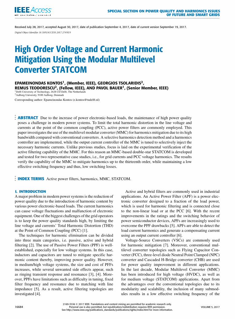
FIGURE 10. DS-STATCOM current (red), load current (black) and gridcurrent (blue) at the PCC of phase-a with harmonic compensation.Grid current has now a %THD of 9%.
FIGURE 11. Grid current at the PCC of phase-a before (red) andafter (blue) harmonic compensation - Time domain. The %THD isreduced by 15%.
FIGURE 12. Grid current at the PCC of phase-a before (red) andafter (blue) harmonic compensation - Frequency domain. The targetharmonics are completely eliminated.
distorted with approximately 26% THD, mainly due to thepresence of the 5th, 7th, 11th and 13th order current harmonics.
Fig. 10 depicts the current waveforms after the applica-tion of the harmonic compensation. It can be seen that theSTATCOM currents are now distorted, while the THD of thegrid currents is effectively reduced to 9%.
A comparative graph in Fig. 11 shows the grid currentsbefore and after the application of the harmonic compensa-tion in the time domain, while Fig. 12 depicts the result ofthe Fast Fourier Transformation (FFT) of the grid currentwaveforms. It can be seen that the injection strategy elimi-nates almost completely the targeted harmonic components inthe grid current, which now appear in the STATCOM outputcurrent. The resulting distortion for each individual harmonicorder is well within the limits defined in [19].
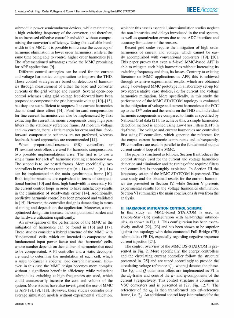
FIGURE 13. PWM signals of first submodule of phase-a when theharmonic compensation is enabled. The sorting algorithm ensuresapproximately equal switching frequency for all submodules.
To estimate the average switching frequency of one sub-module when the harmonic compensation was activated,the PWM signal voltage pulses were monitored for sev-eral cycles. Fig. 13 shows only the recorded number ofPWM pulses fed to the first submodule of phase-a in 100 ms.However, it can be considered that on average the switch-ing frequency is similar for all submodules. It can be seenthat the average effective switching frequency is approxi-mately 0.83 kHz, which is well within the limit of 1 kHz.This result is particularly important since it proves that theMMC-STATCOM can efficiently mitigate high order of har-monics (up to 650 Hz) with the use of low switching fre-quency due to its increased bandwidth.
V. EXPERIMENTAL RESULTS ON VOLTAGEHARMONICS MITIGATIONApart from current harmonics, problems can be created bythe presence of voltage harmonics, which is a common phe-nomenon inweak grids, e.g. in wind power plants. Tomitigatethis problem, STATCOMs are often utilized [40]–[42]. In thisSection, the ability of the developed control system to attenu-ate harmonics at the PCC voltages is assessed experimentally.
The schematic of the used experimental set-up is shownin Fig. 14. In this case, the controllable AC source is usedto emulate the behavior of the wind power plant and isconnected to the isolation transformer through a 2.2 mH lineinductor to emulate the behavior of a grid line.
The harmonics injected by the AC source are controlledand a desired waveform is generated. The control system isthen responsible to sense the harmonic content of the voltageand with the appropriate current injection it should be able tomitigate them, respecting the limits of the grid operator for
FIGURE 14. Schematic of experimental setup for voltage harmonicmitigation.
VOLUME 5, 2017 16689

E. Kontos et al.: High Order Voltage and Current Harmonic Mitigation Using the MMC STATCOM
TABLE 3. Voltage Harmonics at the PCC.
FIGURE 15. Line impedance Z measurements obtained by performingfrequency sweep with an impedance analyzer.
the PCC voltage. The maximum harmonic attenuation thatthe STATCOM can provide is usually limited by its currentrating and the limited available DC link voltage, while it alsodepends on the line inductance.
In this scenario the values for the injected PCC voltage har-monics and their respective limits, as set in [21], are presentedin Table 3. The specified limits are used as references V ∗PCC,nin the closed-loop control scheme presented in Fig. 6. Due tothe aforementioned limitations of the converter, harmonics upto the 11th order are controlled and attenuated. It should alsobe noted that in this case study the converter does not injectreactive current at the fundamental frequency.
A frequency sweep is conducted for the line impedance Zusing an impedance analyzer and its value is measured for fre-quencies up to 1 kHz in order to take the effect of the parasiticelements into consideration. The respective impedance valueat each frequency (Znh) is used for the control of the voltageharmonics as explained in Section II. The measurements arepresented in Fig. 15.
Fig. 16 shows the comparison between the voltage at thePCC before and after the activation of the control systemfor harmonic mitigation. Before, the voltage at the PCC isequal to the voltage generated by the non-ideal controllableAC source taking into account the transformer ratio, sinceno current is flowing in the system, and the THD is 4.9%.The activation of the harmonic compensation results in a sig-nificant reduction in the THD from 4.9% to 3%, as depictedin Fig. 16, in the time domain.
Fig. 17 shows the effectiveness of the voltage mitigationcontrol system of the MMC STATCOM with a comparativegraph in the frequency domain. Considering the defined refer-ences, it can be concluded that the selectivity of the detection
FIGURE 16. Voltage at the PCC of phase-a before (red) and after (blue)harmonic compensation - Time domain. The %THD is reduced by 1.9%.
FIGURE 17. Voltage at the PCC of phase-a before (red) and after (blue)harmonic compensation - Frequency domain. The target harmonics areovercompensated.
and control method for each harmonic component is verified.Moreover, it can be seen that the harmonic components ofall the frequencies of interest follow the specified values asset by the grid codes. Although closed-loop control is used,the obtained values for the harmonic components are slightlybelow the specified limits due to overcompensation resultingfrom the measurement of the line impedance Z . More specif-ically, the impedance values, which are used in the harmonicscontrol (see Fig. 6), were estimated using the impedanceanalyzer at low currents. When the system is operated at highcurrents, close to saturation, the inductor impedance valuecan be higher than the measured one resulting in harmonicsovercompensation. It has to be noted that the average effectiveswitching frequency of the submodules in this case was onceagain recorded to be approximately 0.9 kHz.
VI. CONCLUSIONSRecent grid codes require the compensation of high ordercurrent and voltage harmonics. For this reason, this studyfocussed on the use of the MMC as an active filter to mitigatethose harmonics. A selective harmonics detection methodand an output harmonic current controller were implementedand experimentally verified using a developed MMC pro-totype, which was operated as DS-STATCOM. Tuning wasperformed taking into account the non-linearities of the sys-tem and the delays introduced by the measurements and thecontrol loop, which are usually neglected when approachingthis problem through average model simulations. Finally, tworealistic representative case studies for current and voltageharmonics were defined and tested.
16690 VOLUME 5, 2017
E. Kontos et al.: High Order Voltage and Current Harmonic Mitigation Using the MMC STATCOM
The MMC ability to selectively inject harmonic currentsup to 13th order was proven, while the main limitations wereset by the set-up rating, the number of levels of the MMC andthe available DC link voltage. In fact, it was seen that theincreased bandwidth of theMMC allowed for the grid currentharmonics control up to the 13th order and for PCC volt-age harmonics up to the 11th order, while maintaining theaverage effective switching frequency below 1 kHz and thus,theMMC losses low.More specifically, harmonics mitigationresulted in a reduction of the current THD from 26% downto 9% and of the voltage THD from 4.9% to 3%. Therefore,the advantages of the MMC technology were hereby provenfor active filtering purposes.
REFERENCES[1] S. M. Halpin, ‘‘Comparison of IEEE and IEC harmonic standards,’’
in Proc. IEEE Power Eng. Soc. Gen. Meet., vol. 3. Jun. 2005,pp. 2214–2216.
[2] H. A. Kazem, ‘‘Harmonic mitigation techniques applied to powerdistribution networks,’’ Adv. Power Electron., vol. 2013, Jan. 2013,Art. no. 591680. 591680
[3] R. N. Beres, X. Wang, M. Liserre, F. Blaabjerg, and C. L. Bak, ‘‘A reviewof passive power filters for three-phase grid-connected voltage-sourceconverters,’’ IEEE J. Emerg. Sel. Topics Power Electron., vol. 4, no. 1,pp. 54–69, Mar. 2016.
[4] R. S. Rani, C. S. Rao, and M. V. Kumar, ‘‘Analysis of active power filterfor harmonic mitigation in distribution system,’’ in Proc. Int. Conf. Electr.,Electron., Optim. Techn. (ICEEOT), Mar. 2016, pp. 1338–1446.
[5] D. Schwanz, M. Bollen, A. Larsson, and L. H. Kocewiak, ‘‘Har-monic mitigation in wind power plants: Active filter solutions,’’ inProc. 17th Int. Conf. Harmon. Quality Power (ICHQP), Oct. 2016,pp. 220–225.
[6] C. Lascu, L. Asiminoaei, I. Boldea, and F. Blaabjerg, ‘‘Frequencyresponse analysis of current controllers for selective harmonic compen-sation in active power filters,’’ IEEE Trans. Ind. Electron., vol. 56, no. 2,pp. 337–347, Feb. 2009.
[7] R. E. Betz, T. J. Summers, and G. Mirzaeva, ‘‘Active filtering and VARcontrol of a cascaded H-bridge multi-level StatCom,’’ in Proc. Int. Conf.Power Electron. Drive Syst. (PEDS), Nov. 2009, pp. 816–821.
[8] J. Wu, X. Xu, Y. Liu, and D. Xu, ‘‘Compound control strategy of activepower filter based on modular multilevel converter,’’ in Proc. 11th WorldCongr. Intell. Control Autom. (WCICA), Jun. 2014, pp. 4771–4777.
[9] M. S. Hamad, K. H. Ahmed, and A. I. Madi, ‘‘Current harmonics mitiga-tion using a modular multilevel converter-based shunt active power filter,’’in Proc. IEEE Int. Conf. Renew. Energy Res. Appl. (ICRERA), Nov. 2016,pp. 755–759.
[10] M. Liserre, R. Teodorescu, and F. Blaabjerg, ‘‘Multiple harmonics controlfor three-phase grid converter systems with the use of PI-RES currentcontroller in a rotating frame,’’ IEEE Trans. Power Electron., vol. 21, no. 3,pp. 836–841, May 2006.
[11] M. Castilla, J. Miret, A. Camacho, J. Matas, and L. G. de Vicuna, ‘‘Reduc-tion of current harmonic distortion in three-phase grid-connected photo-voltaic inverters via resonant current control,’’ IEEE Trans. Ind. Electron.,vol. 60, no. 4, pp. 1464–1472, Apr. 2013.
[12] J. Xu, Q. Qian, S. Xie, and B. Zhang, ‘‘Grid-voltage feedforward basedcontrol for grid-connected LCL-filtered inverter with high robustness andlow grid current distortion in weak grid,’’ in Proc. IEEE Appl. PowerElectron. Conf. Expo. (APEC), Mar. 2016, pp. 1919–1925.
[13] D. Wu and L. Peng, ‘‘Analysis and suppressing method for the outputvoltage harmonics of modular multilevel converter,’’ IEEE Trans. PowerElectron., vol. 31, no. 7, pp. 4755–4765, Jul. 2016.
[14] S. Madhusoodhanan et al., ‘‘Harmonic analysis and controller designof 15 kV SiC IGBT-based medium-voltage grid-connected three-phasethree-level NPC converter,’’ IEEE Trans. Power Electron., vol. 32, no. 5,pp. 3355–3369, May 2017.
[15] Z. Shu, M. Liu, L. Zhao, S. Song, Q. Zhou, and X. He,‘‘Predictive harmonic control and its optimal digital implementation forMMC-based active power filter,’’ IEEE Trans. Ind. Electron., vol. 63, no. 8,pp. 5244–5254, Aug. 2016.
[16] J. A. Munoz, J. R. Espinoza, C. R. Baier, L. A. Moran, J. I. Guzman,and V. M. Cardenas, ‘‘Decoupled and modular harmonic compensationfor multilevel STATCOMs,’’ IEEE Trans. Ind. Electron., vol. 61, no. 6,pp. 2743–2753, Jun. 2014.
[17] J. A. Munoz, J. R. Espinoza, C. R. Baier, L. A. Moran, and J. I. Guzman,‘‘Modular harmonic cancellation in amultilevel STATCOM,’’ inProc. 37thAnnu. Conf. IEEE Ind. Electron. Soc. (IECON), Nov. 2011, pp. 4146–4151.
[18] F. T. Ghetti, A. A. Ferreira, H. A. C. Braga, and P. G. Barbosa, ‘‘A study ofshunt active power filter based on modular multilevel converter (MMC),’’in Proc. 10th IEEE/IAS Int. Conf. Ind. Appl., Nov. 2012, pp. 1–6.
[19] IEEE Recommended Practice and Requirements for Harmonic Controlin Electric Power Systems, IEEE Standard 519-2014 (Revision of IEEEStandard 519-1992), Jun. 2014, pp. 1–29.
[20] Planning Levels for Harmonic Voltage Distortion and Connection ofNon-Linear Equipment to Transmission and Distribution Networks inthe UK, document Engineering Recommendation (ER) G5/4-1, Issue 4,Amendment 1, Oct. 2005.
[21] N. Grid, ‘‘Generator self build enduring regime harmonic assessmentprocess flow,’’ Nat. Grid, U.K., Tech. Rep., Oct. 2005.
[22] H. P. Mohammadi and M. T. Bina, ‘‘A transformerless medium-voltageSTATCOM topology based on extended modular multilevel converters,’’IEEE Trans. Power Electron., vol. 26, no. 5, pp. 1534–1545, May 2011.
[23] A. António-Ferreira, O. Gomis-Bellmunt, and M. Teixidó, ‘‘HVDC-basedmodular multilevel converter in the statcom operationmode,’’ inProc. 18thEur. Conf. Power Electron. Appl. (EPE’ECCE Eur.), Sep. 2016, pp. 1–10.
[24] G. P. Tsolaridis, H. A. Pereira, A. F. Cupertino, R. Teodorescu, andM. Bongiorno, ‘‘Losses and cost comparison of DS-HB and SD-FB MMCbased large utility grade STATCOM,’’ in Proc. IEEE 16th Int. Conf.Environ. Electr. Eng. (EEEIC), Jun. 2016, pp. 1–6.
[25] G. P. Tsolaridis, E. Kontos, S. K. Chaudhary, P. Bauer, and R. Teodorescu,‘‘Internal balance during low-voltage-ride-through of the modular multi-level converter STATCOM,’’ Energies, vol. 10, no. 7, p. 935, 2017.
[26] R. Teodorescu, M. Liserre, and P. Rodríguez, Grid Converters for Photo-voltaic and Wind Power Systems. Hoboken, NJ, USA: Wiley, 2011.
[27] K. Sharifabadi, L. Harnefors, H.-P. Nee, S. Norrga, and R. Teodorescu,Design, Control and Application of Modular Multilevel Converters forHVDC Transmission Systems, 1st ed. Hoboken, NJ, USA: Wiley, 2016.
[28] L. Asiminoael, F. Blaabjerg, and S. Hansen, ‘‘Detection is key—Harmonicdetection methods for active power filter applications,’’ IEEE Ind. Appl.Mag., vol. 13, no. 4, pp. 22–33, Jul. 2007.
[29] P. Lauttamus and H. Tuusa, ‘‘Three-level VSI based low switching fre-quency 10 MVA STATCOM in reactive power and harmonics compen-sation,’’ in Proc. 7th Int. Conf. Power Electron. (ICPE), Oct. 2007,pp. 536–541.
[30] S. Rechka, E. Ngandui, J. Xu, and P. Sicard, ‘‘Analysis of harmonic detec-tion algorithms and their application to active power filters for harmonicscompensation and resonance damping,’’ Can. J. Electr. Comput. Eng.,vol. 28, no. 1, pp. 41–51, Jan. 2003.
[31] T. Nussbaumer, M. L. Heldwein, G. Gong, S. D. Round, and J. W. Kolar,‘‘Comparison of prediction techniques to compensate time delays causedby digital control of a three-phase buck-type PWM rectifier system,’’ IEEETrans. Ind. Electron., vol. 55, no. 2, pp. 791–799, Feb. 2008.
[32] A. Safaee, D. Yazdani, A. Bakhshai, and P. Jain, ‘‘Three-phase har-monic detection methods for grid-connected converters,’’ in Proc. 26thAnnu. IEEE Appl. Power Electron. Conf. Expo. (APEC), Mar. 2011,pp. 1357–1361.
[33] B. Shenoi, Introduction to Digital Signal Processing and Filter Design.Hoboken, NJ, USA: Wiley, 2005.
[34] R. Teodorescu, F. Blaabjerg, M. Liserre, and P. C. Loh, ‘‘Proportional-resonant controllers and filters for grid-connected voltage-source con-verters,’’ IEE Proc.-Electr. Power Appl., vol. 153, no. 5, pp. 750–762,Sep. 2006.
[35] P. R. Babu, R. Agrawal, S. R. Paital, S. S. Raju, and S. Raju, ‘‘Novelmethods of detection of harmonics,’’ Int. J. Eng. Innov. Technol. (IJEIT),vol. 2, no. 11, pp. 167–173, May 2013.
[36] M. Gonzalez, V. Cardenas, and F. Pazos, ‘‘DQ transformation developmentfor single-phase systems to compensate harmonic distortion and reactivepower,’’ in Proc. 9th IEEE Int. Power Electron. Congr. (CIEP), Oct. 2004,pp. 177–182.
[37] Z. Xin, Z. Qin, M. Lu, P. C. Loh, and F. Blaabjerg, ‘‘A new second-ordergeneralized integrator based quadrature signal generator with enhancedperformance,’’ in Proc. IEEE Energy Convers. Congr. Expo. (ECCE),Sep. 2016, pp. 1–7.
VOLUME 5, 2017 16691

E. Kontos et al.: High Order Voltage and Current Harmonic Mitigation Using the MMC STATCOM
[38] G. Tsolaridis, E. Kontos, H. Parikh, R. M. Sanchez-Loeches,R. Teodorescu, and S. K. Chaudhary, ‘‘Control of a modular multilevelconverter STATCOM under internal and external unbalances,’’ inProc. 42nd Annu. Conf. IEEE Ind. Electron. Soc. (IECON), Oct. 2016,pp. 6494–6499.
[39] M. Sakui and H. Fujita, ‘‘An analytical method for calculating harmoniccurrents of a three-phase diode-bridge rectifier with DC filter,’’ IEEETrans. Power Electron., vol. 9, no. 6, pp. 631–637, Nov. 1994.
[40] S. K. Chaudhary, C. Lascu, R. Teodorescu, and L. H. Kocewiak, ‘‘Voltagefeedback based harmonic compensation for an offshore wind power plant,’’in Proc. IEEE Int. Conf. Power Electron., Drives Energy Syst. (PEDES),Dec. 2016, pp. 1–5.
[41] S. K. Chaudhary et al., ‘‘Challenges with harmonie compensation at aremote bus in offshore wind power plant,’’ in Proc. IEEE 16th Int. Conf.Environ. Electr. Eng. (EEEIC), Jun. 2016, pp. 1–6.
[42] L. H. Kocewiak et al., ‘‘Power quality improvement of wind power plantsby active filters embedded in statcoms,’’ inProc. 15th Int. Workshop Large-Scale Integr. Wind Power Into Power Syst. As Well As Transmiss. Netw.Offshore Wind Farms, Nov. 2016.
EPAMEINONDAS KONTOS (M’14) received theDiploma degree in electrical and computer engi-neering from the National Technical University ofAthens, Athens, Greece, in 2010, and the M.Sc.(cum laude) degree in sustainable energy tech-nology from the Delft University of Technology,Delft, The Netherlands, in 2013. During his stud-ies, he was an Intern for three months with SMASolar Technology AG, Kassel, Germany. Since2013, he has been a Ph.D. Researcher on the TKI
Synergies at Sea Project with the DCE&S Group of TU Delft. His interestsinclude the design of multi-level modular converters for HVDC applications,protection system design for multi-terminal HVDC grids, and the control ofpower electronics.
GEORGIOS TSOLARIDIS received the degree inelectrical and computer engineering with special-ization in power engineering from the AristotleUniversity of Thessaloniki, Greece, the Diplomadegree in 2014, and the master’s degree in powerelectronics and drives from Aalborg University,Denmark, in 2016. He is currently pursuing thePh.D. degree with the Laboratory for High PowerElectronic Systems, ETH Zurich. During his stud-ies, he was with the ABB’s Corporate Research
Center, Vasteras, Sweden, as an Intern for six months.
REMUS TEODORESCU (F’12) received theDipl.Ing. degree in electrical engineering from thePolytechnical University of Bucharest, Bucharest,Romania, in 1989, and the Ph.D. degree inpower electronics from the University of Galati,Romania, in 1994. In 1998, he joined the PowerElectronics Section, Department of Energy Tech-nology, Aalborg University, Aalborg, Denmark,where he is currently a Full Professor. Since2013, he has been a Visiting Professor with
Chalmers University. His research interests include the design and controlof grid-connected converters for photovoltaic and wind power systems,HVDC/FACTS based on modular multilevel converters, and storage sys-tems based on Li-ion battery technology, including modular converters andactive BMS.
PAVOL BAUER (SM’07) is currently a Full Pro-fessor with the Department of Electrical Sus-tainable Energy, Delft University of Technologyand the Head of the DC Systems, Energy Con-version and Storage Group. He has authored orco-authored over 80 journal and 300 conferencepapers in his field (with h-factor Google scholar33,Web of science 21), he is an author or co-authorof eight books, holds four international patentsand organized several tutorials at the international
conferences. He was involved in many projects for industry concerningwind and wave energy, power electronic applications for power systems,such as Smarttrafo; HVDC systems, projects for smart cities, such asPV charging of electric vehicles, PV and storage integration, contactlesscharging; and he participated in several Leonardo da Vinci and H2020 EUprojects as a Project Partner (ELINA, INETELE, E-Pragmatic) and Coor-dinator (PEMCWebLab.com-Edipe, SustEner, Eranet DCMICRO). He is aFormer Chairman of Benelux IEEE Joint Industry Applications Society,Power Electronics and Power Engineering Society Chapter, the Chairmanof the Power Electronics and Motion Control Council, a member of theExecutive Committee of European Power Electronics Association, and alsoa member of International Steering Committee at numerous conferences.
16692 VOLUME 5, 2017