aalborg universitet tuning of voltage controller gain for ... · aalborg universitet tuning of...
TRANSCRIPT

Aalborg Universitet
Tuning of Voltage Controller Gain for Multiple STATCOM Systems
Steinkohl, Joachim; Wang, Xiongfei
Published in:Proceedings of 2018 IEEE 19th Workshop on Control and Modeling for Power Electronics (COMPEL)
DOI (link to publication from Publisher):10.1109/COMPEL.2018.8460094
Publication date:2018
Document VersionAccepted author manuscript, peer reviewed version
Link to publication from Aalborg University
Citation for published version (APA):Steinkohl, J., & Wang, X. (2018). Tuning of Voltage Controller Gain for Multiple STATCOM Systems. InProceedings of 2018 IEEE 19th Workshop on Control and Modeling for Power Electronics (COMPEL) (pp. 1-6).[8460094] IEEE Press. https://doi.org/10.1109/COMPEL.2018.8460094
General rightsCopyright and moral rights for the publications made accessible in the public portal are retained by the authors and/or other copyright ownersand it is a condition of accessing publications that users recognise and abide by the legal requirements associated with these rights.
? Users may download and print one copy of any publication from the public portal for the purpose of private study or research. ? You may not further distribute the material or use it for any profit-making activity or commercial gain ? You may freely distribute the URL identifying the publication in the public portal ?
Take down policyIf you believe that this document breaches copyright please contact us at [email protected] providing details, and we will remove access tothe work immediately and investigate your claim.
Downloaded from vbn.aau.dk on: April 04, 2020

Tuning of Voltage Controller Gain for MultipleSTATCOM Systems
Joachim Steinkohl∗ and Xiongfei Wang†Department of Energy Technology
Aalborg UniversityAalborg, Denmark
∗[email protected], †[email protected]
Abstract—STATCOMs with voltage control are known for theirfast reaction time to stabilize the grid voltage. For optimaldynamic performance it is essential to use the correct gainsettings for the PI voltage regulation controller, adapted fordifferent states of operation. This paper shows the equation tocalculate the accurate value for the gain setting in the voltagecontroller. The inner control behavior with enabled droop controlis considered as well as the strength of the grid. After this theinfluences between STATCOMs installed in parallel in one busis shown and the adaption of the gain to take this into accountis calculated. The equations are validated by analytic aspectsas well as by simulations. This enhances the existing controlsolution in industry and allows constant dynamic performanceunder various system changes in future grids.
Index Terms—FACTS, STATCOM, Voltage Control
I. INTRODUCTION
A Static Compensator (STATCOM) is a device for advancedreactive power compensation to vontrol the voltage in thepower grid [1]. It can be used to control power factor, reg-ulate voltage, stabilize power flow, and improve the dynamicperformance of power systems. It has been well understoodthat the voltage control of a STATCOM is highly dependenton the conditions in the grid it is connected to, especiallyto system strength [2] and to other dynamical voltage con-trolling devices. Without adapting to these conditions controlinstabilities occur [3]. Other research has focused on adaptivecontroller settings [4]–[6] or fuzzy control [7]. All thesecontrol techniques lack on the calculated adjustment of thevoltage controller gain to the influences of other STATCOMs.
To prevent instabilities and to maintain optimal dynamicperformances, communications between the FACTS devicesare installed to reduce the gain of the voltage controllersby a constant factor [3]. But this control adaption does notguarantee constant dynamic performances. This paper showsthe calculation for the optimal gain adaption for the voltagecontroller in a multiple STATCOM system. This allows tohave constant dynamic performances for different systemconditions.
II. STATCOM GAIN CALCULATION
The gain calculation for a single STATCOM installation isdetermined at first. For this, the needed reactive output of aSTATCOM due to a voltage deviation is calculated. Then theinfluences of other STATCOMs are taken into account as well.
A. Single STATCOM installation
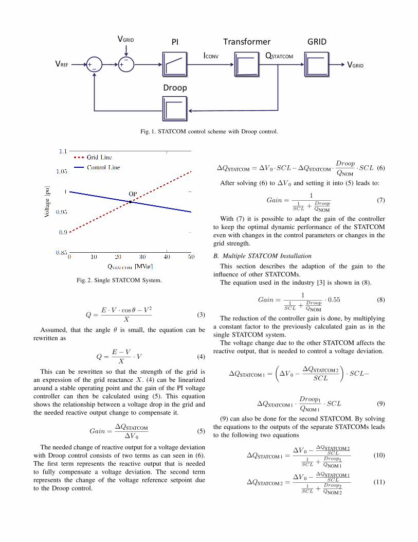
The control scheme of the STATCOM voltage controllerwith droop control is shown in Fig. 1. The inner current controlis not shown, it can be neglected for this analysis, due tothe slower dynamics. The reactive output of the STATCOMis fed back to change the voltage reference value. This isbeneficial for keeping dynamic reserve in the system and toavoid instabilities with multiple voltage controlling devices.
The proportional-integral (PI) controller of the voltage con-troller has the form
Gain ·(
1 +1
TN · s
)(1)
With this form of the PI controller is it possible to adaptto changes in the grid strength and the Droop control. TNhas to be set according to internal time constants such as themeasurement delays. The Droop control is used to allow loadsharing between multiple units. This allows the operators toreduce the impact of the STATCOMs under normal operatingconditions [8].
The controlled positive phase sequence grid voltage insteady state is expressed in (2). This shows the deviation fromthe reference voltage due to the Droop control.
V GRID = V REF −QSTATCOM · DroopQNOM
(2)
Fig. 2 shows the crossing of the Grid Line (determined bythe grid strength) and the Control Line (determined by theDroop control) in a single STATCOM system. The point ofcrossing determines the operating point of the STATCOMunder steady state conditions.
The Droop control has to be taken into account for thegain calculation, because it has a severe impact on the neededreactive power output due to a change in the grid voltage. Ittherefore changes the point of operation in the steady state. Ifit is not taken into account, the step response time and settlingtime of the STATCOM do not forfill the specifications for thevoltage controlling dynamics [2]. The equation for the reactivepower flow can be used to express the impact of the reactiveoutput power of a STATCOM to the voltage difference, thatis caused by this output.
VGRID
VREF
PI GRIDTransformer
Droop
VGRID
ICONV QSTATCOM
Fig. 1. STATCOM control scheme with Droop control.
Fig. 2. Single STATCOM System.
Q =E · V · cos θ − V 2
X(3)
Assumed, that the angle θ is small, the equation can berewritten as
Q =E − V
X· V (4)
This can be rewritten so that the strength of the grid isan expression of the grid reactance X . (4) can be linearizedaround a stable operating point and the gain of the PI voltagecontroller can then be calculated using (5). This equationshows the relationship between a voltage drop in the grid andthe needed reactive output change to compensate it.
Gain =∆QSTATCOM
∆V 0(5)
The needed change of reactive output for a voltage deviationwith Droop control consists of two terms as can seen in (6).The first term represents the reactive output that is neededto fully compensate a voltage deviation. The second termrepresents the change of the voltage reference setpoint dueto the Droop control.
∆QSTATCOM = ∆V 0 ·SCL−∆QSTATCOM ·DroopQNOM
·SCL (6)
After solving (6) to ∆V 0 and setting it into (5) leads to:
Gain =1
1SCL + Droop
QNOM
(7)
With (7) it is possible to adapt the gain of the controllerto keep the optimal dynamic performance of the STATCOMeven with changes in the control parameters or changes in thegrid strength.
B. Multiple STATCOM Installation
This section describes the adaption of the gain to theinfluence of other STATCOMs.
The equation used in the industry [3] is shown in (8).
Gain =1
1SCL + Droop
QNOM
· 0.55 (8)
The reduction of the controller gain is done, by multiplyinga constant factor to the previously calculated gain as in thesingle STATCOM system.
The voltage change due to the other STATCOM affects thereactive output, that is needed to control a voltage deviation.
∆QSTATCOM 1 =
(∆V 0 −
∆QSTATCOM 2
SCL
)· SCL−
∆QSTATCOM 1 ·Droop1
QNOM 1· SCL (9)
(9) can also be done for the second STATCOM. By solvingthe equations to the outputs of the separate STATCOMs leadsto the following two equations
∆QSTATCOM 1 =∆V 0 −
∆QSTATCOM 2SCL
1SCL +
Droop1QNOM 1
(10)
∆QSTATCOM 2 =∆V 0 −
∆QSTATCOM 1SCL
1SCL +
Droop2QNOM 2
(11)

With these equations it is possible to determine the optimalchange of reactive output of the two STATCOMs dependingon the voltage deviation in the grid even with unequal ratingsand control settings. Solving the two equations (10) and (11)with the same STATCOM ratings (QNOM) and control settings(Droop) entered in (5) leads to (12) as a gain for bothSTATCOM units.
Gain =1
2SCL + Droop
QNOM
(12)
Therefore a second STATCOM changes the gradient of thegrid line shown in Fig. 3 following (12).
For this, the diagram for the STATCOM effect on thesystem voltage has been redrawn to take the effect of a secondSTATCOM into account. This is done by changing the slopeof the grid line.
Fig. 3. Multiple STATCOM System.
The influence of a second STATCOM is taken into accountin (6). The other STATCOM changes the voltage in the grid,but not the reactive output that is taken into consideration inthe Droop control term. This can be seen also in [3], where thetime constant of the control system is changed according tothe droop, the grid strength and the existence of other voltagecontrolling devices.
This equation is not exactly the equation, that is used in theindustry, both solutions are further analyzed in Section IV.
The gain can now be calculated for all values of the SCLand Droop settings. The proposed equation allows constant dy-namic performances even with changed control parameters andgrid conditions. This is shown in simulations in Section IV.
C. Not equally sized STATCOMsIf there are STATCOMs installed close to each other with
different reactive output ratings, then the equation has tochange according to the nominal reactive power to the sumof all nominal reactive powers together.
Gain1 =1
1SCL · QNOM 1+QNOM 2
QNOM 1+ Droop
QNOM
(13)
and
Gain2 =1
1SCL · QNOM 1+QNOM 2
QNOM 2+ Droop
QNOM
(14)
The calculated gains in (13) and (14), that can be calculatedfrom (10) and (11) allow the correct control of STATCOMswith different ratings in the same power grid. It is assumedthat the Droop control is the same in both units, because theyare installed in one power system with the same grid code. Ifthe Droop control set points are different, it is still possible tocalculate the optimal gain following the equations from above.
D. Multiple STATCOM Installation
With more than two STATCOMs installed at one bus, theinfluence of these STATCOMs can also be taken into accountfor the gain calculation. The voltage deviation that has to becontrolled by the different STATCOMs can be calculated toget an expression for the influences of all other STATCOMsto the individual ones. (15) demonstrates the influence of allother STATCOMs to one STATCOM.
∆QSTATCOM 1 =
(∆V 0 −
N∑i=2
∆QSTATCOM i
SCL
)· SCL−
∆QSTATCOM 1 ·Droop1
QNOM 1· SCL (15)
The gain of the voltage controllers can be calculated follow-ing the same calculations as for (12). Solving these equationsagain with the same ratings and controller settings leads to(16).
Gain =1
NSCL + Droop
QNOM
(16)
With N in (16) being defined as the total number of identicalSTATCOMs in one bus. This formula is only applicable withthe same Droop control settings and ratings of all STATCOMsinstalled in one bus. Different STATCOM ratings can also beexpressed and calculated with respect to (17).
Gaini =1
1SCL ·
N∑i=1
QNOM i
QNOM i+ Droop
QNOM i
(17)
This allows the constant dynamic performance of a widevariety of possible STATCOM configurations.
III. ANALYSIS
To determine the impact of the different gain calculationmethods, an analytic approach is needed. For this, thecontrol system from Fig. 1 is analyzed. The filter for themeasurement of the reactive output and also for the gridvoltage is simplified to a first order low-pass filter. This slowsdown the control in such a way, that the step response ofthe closed loop control meets the dynamics as in a modern

transmission STATCOM installation.
The bode diagrams of the closed-loop system with the gainreduction method as in (8), used in industry, are shown. Forthis, the system is analyzed with a droop of 10 % (in Fig. 4)and 4 % (in Fig. 5). The strength of the power system ischanged in 5 GVA steps from 0.5 GVA to 20.5 GVA in bothcases.
Fig. 4. Bode plot with SCL variations withfixed reduction factor with 10 % Droop.
It can be seen in the lower graphs in Fig. 4 that the timeresponse of the system is not constant with the variation of thegrid strength. This causes unwanted dynamics in the operationof the STATCOM system in a wide variety of grid conditions,if there are other voltage controlling devices nearby. The droopcontrol affects the steady state operation point as one can seeby the deviation of 0 db in the upper graph.
With reduced droop control setpoint the system variationsin steady state are smaller than with 10 % droop. Nevertheless,the dynamic variations are still visible and the dynamicsof the system are not constant under changing grid conditions.
Afterwards, the closed-loop behavior with the proposed gainreduction as in (12) is analyzed. Fig. 6 and Fig. 7 show thebode plots of the closed-loop system with the proposed gaintuning equation. The SCL variations are the same as in theprevious analysis.
The time response of the system shown in Fig. 6 is constantand does not change with the SCL variations. The steady stateoperation point is still varying due to the different effects of theSTATCOM output to the grid voltage under droop control. Thedeviations under steady state are exactly the same as in Fig. 4,because the gain control adaption only affects the dynamicsof the control system.
Fig. 7 proves also the constant dynamic behavior of thesystem under changed grid and control conditions. The steady
Fig. 5. Bode plot with SCL variations withfixed reduction factor with 4 % Droop.
Fig. 6. Bode plot with SCL variations withproposed gain tuning with 10 % Droop.
state operation points are again the same as in Fig. 5.
The proposed gain tuning is therefore enhancing the dy-namic behavior of the voltage in the power grid. This systembehavior is also tested with step response tests in simulations,to further verify the performance under more detailed condi-tions.
IV. SIMULATION
The theoretical results have been verified with simulationsto see if the equations for the gain calculation are correct andthat they improve the dynamic response of the STATCOM
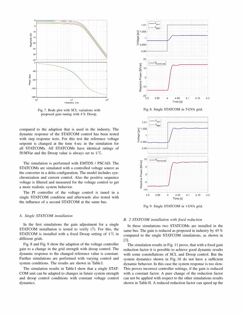
Fig. 7. Bode plot with SCL variations withproposed gain tuning with 4 % Droop.
compared to the adaption that is used in the industry. Thedynamic response of the STATCOM control has been testedwith step response tests. For this test the reference voltagesetpoint is changed at the time 4 sec in the simulation forall STATCOMs. All STATCOMs have identical ratings of50 MVar and the Droop value is always set to 4 %.
The simulation is performed with EMTDS / PSCAD. TheSTATCOMs are simulated with a controlled voltage source asthe converter in a delta configuration. The model includes syn-chronization and current control. Also the positive sequencevoltage is filtered and measured for the voltage control to geta more realistic system behavior.
The PI controller of the voltage control is tuned in asingle STATCOM condition and afterwards also tested withthe influence of a second STATCOM at the same bus.
A. Single STATCOM installation
In the first simulations the gain adjustment for a singleSTATCOM installation is tested to verify (7). For this, theSTATCOM is installed with a fixed Droop setting of 4 % indifferent grids.
Fig. 8 and Fig. 9 show the adaption of the voltage controllergain to a change in the grid strength with droop control. Thedynamic response to the changed reference value is constant.Further simulations are performed with varying control andsystem conditions. The results are shown in Table I.
The simulation results in Table I show that a single STAT-COM unit can be adapted to changes in future system strengthand droop control conditions with constant voltage controldynamics.
Fig. 8. Single STATCOM in 5 GVA grid.
Fig. 9. Single STATCOM in 1 GVA grid.
B. 2 STATCOM installation with fixed reduction
In these simulations two STATCOMs are installed in thesame bus. The gain is reduced as proposed in industry by 45 %compared to the single STATCOM simulations, as shown in[3].
The simulation results in Fig. 11 prove, that with a fixed gainreduction factor it is possible to achieve good dynamic resultswith some constellations of SCL and Droop control. But thesystem dynamics shown in Fig. 10 do not have a sufficientdynamic behavior. In this case the system response is too slow.This proves incorrect controller settings, if the gain is reducedwith a constant factor. A pure change of the reduction factorcan not be applied with respect to the other simulations resultsshown in Table II. A reduced reduction factor can speed up the

TABLE ISimulation Results with single STATCOM installation
Droop Rise Time Overshoot
1 % 25 ms 2 %
1 GVA 2 % 25 ms 3 %
4 % 26 ms 2 %
1 % 27 ms 1 %
5 GVA 2 % 25 ms 2 %
4 % 26 ms 2 %
1 % 26 ms 2 %
10 GVA 2 % 27 ms 1 %
4 % 25 ms 3 %
Fig. 10. 2 STATCOMs in 5 GVA grid.With fixed Gain adaption as used in industry.
control in some grid conditions, other conditions in the gridwill then lead to high overshoots that are not allowed for astable grid operation (as in the first test result in Table II).
Table II shows the dynamic behavior of the tested setupwith the constant gain reduction of 45%. This adaption isnot sufficient under all conditions. The overshoots are in thespecified limits, due to the value of the reduction. But therise time increases to very high values (up to 44 ms in theperformed simulations). This method will therefore limit theoptimal dynamic operation range of the STATCOM voltagecontrol.
C. 2 STATCOM installation with proposed calculation
In the following simulations the proposed gain reduction isused.
Fig. 11. 2 STATCOMs in 1 GVA grid.With fixed Gain adaption as used in industry.
TABLE IISimulation Results with double STATCOM installation with fixed
Gain Reduction as used in industry
Droop Rise Time Overshoot
1 % 25 ms 4 %
1 GVA 2 % 26 ms 3 %
4 % 27 ms 1 %
1 % 26 ms 1 %
5 GVA 2 % 31 ms 0 %
4 % 38 ms 0 %
1 % 29 ms 0 %
10 GVA 2 % 37 ms 0 %
4 % 44 ms 0 %
The simulation results shown in Fig. 12 and Fig. 13 provethe correct adaption of the STATCOM controller to the influ-ence of a second STATCOM installed in the same bus withthe proposed gain tuning. The time to reach the new steadystate operation is constant and the overshoots of the controllerare always low enough to fulfill the requirements for stablegrid operation.
The results of the dynamic analysis are shown in Table III.It can be seen, that the proposed gain tuning method allowsto keep a constant dynamic performance, even with theinstallation of a second STATCOM unit close nearby.
Also simulations are performed with different STATCOMnominal reactive outputs. This leads to the conclusion, that(13) and (14) are valid and enable constant system dynamics.

Fig. 12. 2 STATCOMs in 5 GVA grid.With proposed Gain adaption.
Fig. 13. 2 STATCOMs in 1 GVA grid.With proposed Gain adaption.
The used nominal reactive outputs used for the simulations are50 MVar in one STATCOM and then variations in the secondSTATCOMs nominal reactive power (50 MVar, 25 MVar and10 MVar). The simulation results are not shown here, theycorrespond almost to the results shown in Table III.
V. CONCLUSION
The simulations performed in this paper proves the correct-ness of the equation for adapting the controller gain. So it ispossible to achieve optimal dynamic response to voltage devi-ations from the STATCOM in all analyzed system conditionswith the proposed gain adaption method. The equation usedin the industry right now is not sufficient to adapt to multiple
TABLE IIISimulation Results with double STATCOM installation with
proposed Gain Reduction
Droop Rise Time Overshoot
1 % 25 ms 2 %
1 GVA 2 % 25 ms 3 %
4 % 26 ms 2 %
1 % 27 ms 1 %
5 GVA 2 % 25 ms 2 %
4 % 26 ms 2 %
1 % 26 ms 3 %
10 GVA 2 % 27 ms 2 %
4 % 27 ms 2 %
STATCOMs in a correct way. This can lead to unwantedbehavior during severe grid events.
Further investigation is needed to the influence of dis-tances and therefore impedance between different STATCOMunits. This changes the impact of the reactive power of oneSTATCOM to the measured voltage on the other STATCOM.Therefore it affects the optimal gain that is needed for constantdynamics. Due to the high number of possible grid configu-rations has it not been included.
REFERENCES
[1] N. G. Hingorani, L. Gyugyi, and M. El-Hawary, Understanding FACTS:concepts and technology of flexible AC transmission systems. WileyOnline Library, 2000, vol. 2.
[2] G. Romegialli and H. Beeler, “Reactive compensation. Problems and con-cepts of static compensator control,” in IEE Proceedings C (Generation,Transmission and Distribution), vol. 128, no. 6. IET, 1981, pp. 382–388.
[3] Coordination of Controls of Multiple FACTS/HVDC Links in the SameSystem, ser. Brochures thematiques: International Conference on LargeHigh Voltage Electric Systems. CIGRE, 1999.
[4] Y. Xu and F. Li, “Adaptive PI Control of STATCOM for VoltageRegulation,” IEEE Transactions on Power Delivery, vol. 29, no. 3, pp.1002–1011, June 2014.
[5] J.-x. Xu, L.-c. Xiu, C.-c. Hang, C. Li, Q.-r. Jiang, and Z.-h. Wang, “PIcontrol of STATCOM using fuzzy set and auto-tuning techniques,” IFACProceedings Volumes, vol. 32, no. 2, pp. 7340–7345, july 1999.
[6] Y. Xu, F. Li, Z. Jin, and C. Huang, “Flatness-based adaptive control(FBAC) for STATCOM,” Electric Power Systems Research, vol. 122, pp.76–85, 2015.
[7] S. A. Al-Mawsawi, M. Qader, and G. Ali, “Dynamic controllers designfor STATCOM,” Iranian journal of electrical and computer engineering,vol. 3, no. 1, pp. 16–22, 2004.
[8] L. Gyugyi, “Power electronics in electric utilities: static VAR compen-sators,” Proceedings of the IEEE, vol. 76, no. 4, pp. 483–494, Apr 1988.