about omics group - d2cax41o7ahm5l.cloudfront.net · about omics group conferences ... dubai,...
TRANSCRIPT

About OMICS Group
OMICS Group International is an amalgamation of Open Access publications and worldwide international science conferences and events. Established in the year 2007 with the sole aim of making the information on Sciences and technology ‘Open Access’, OMICS Group publishes 400 online open access scholarly journals in all aspects of Science, Engineering, Management and Technology journals. OMICS Group has been instrumental in taking the knowledge on Science & technology to the doorsteps of ordinary men and women. Research Scholars, Students, Libraries, Educational Institutions, Research centers and the industry are main stakeholders that benefitted greatly from this knowledge dissemination. OMICS Group also organizes 300 International conferences annually across the globe, where knowledge transfer takes place through debates, round table discussions, poster presentations, workshops, symposia and exhibitions.
About OMICS Group Conferences
OMICS Group International is a pioneer and leading science
event organizer, which publishes around 400 open access
journals and conducts over 300 Medical, Clinical, Engineering,
Life Sciences, Pharma scientific conferences all over the globe
annually with the support of more than 1000 scientific
associations and 30,000 editorial board members and 3.5
million followers to its credit.
OMICS Group has organized 500 conferences, workshops and
national symposiums across the major cities including San
Francisco, Las Vegas, San Antonio, Omaha, Orlando, Raleigh,
Santa Clara, Chicago, Philadelphia, Baltimore, United Kingdom,
Valencia, Dubai, Beijing, Hyderabad, Bengaluru and Mumbai.
Bio-Fuels Combustion Research
An Integrative Approach
with a Focus on
The Research Program at the
School of Aerospace and Mechanical Engineering
The University of Oklahoma
Presented by
S. R. Gollahalli Professor and Lesch Centennial Chair

Why Alternative Fuels?
• Global Climate
Change
• Energy Independence
• Oil is a Limited
Resource
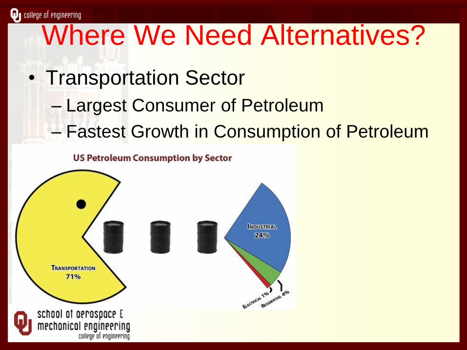
Where We Need Alternatives?
• Transportation Sector
– Largest Consumer of Petroleum
– Fastest Growth in Consumption of Petroleum
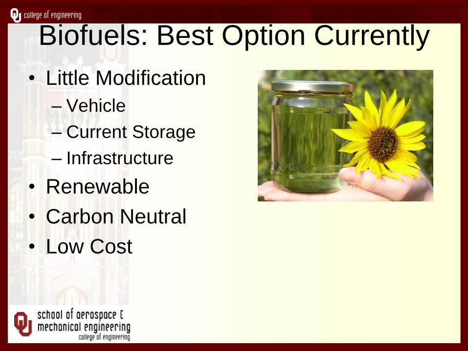
Biofuels: Best Option Currently
• Little Modification
– Vehicle
– Current Storage
– Infrastructure
• Renewable
• Carbon Neutral
• Low Cost
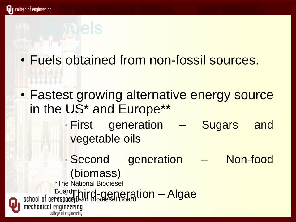
• Fuels obtained from non-fossil sources.
• Fastest growing alternative energy source in the US* and Europe**
• First generation – Sugars and
vegetable oils
• Second generation – Non-food
(biomass)
• Third-generation – Algae *The National Biodiesel
Board
**European Biodiesel Board
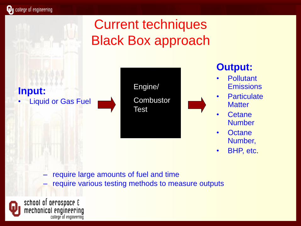
Current techniques
Black Box approach
– require large amounts of fuel and time
– require various testing methods to measure outputs
Input:
• Liquid or Gas Fuel
Engine/
Combustor
Test
Output: • Pollutant
Emissions
• Particulate Matter
• Cetane Number
• Octane Number,
• BHP, etc.
Laboratories
Combustion and Flame Dynamics Lab
Internal Combustion Engines Lab
Aero-Propulsion Lab
Fire Research Lab

Focus
To Understand Fundamental
Thermochemical Processes in Bio-
fuel Combustion relative to
Petroleum fuel-Combustion in
Different Combustors
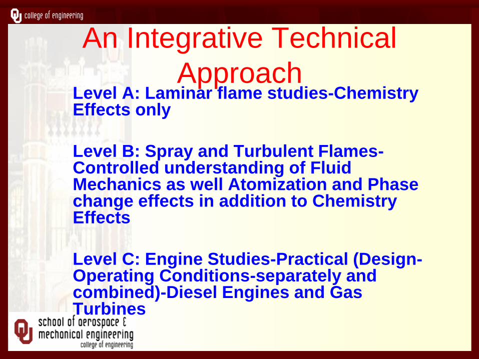
An Integrative Technical
Approach Level A: Laminar flame studies-Chemistry Effects only
Level B: Spray and Turbulent Flames-Controlled understanding of Fluid Mechanics as well Atomization and Phase change effects in addition to Chemistry Effects
Level C: Engine Studies-Practical (Design-Operating Conditions-separately and combined)-Diesel Engines and Gas Turbines

Technical Approach (Cont'
• Level D: Novel Burner Development
(Porous Media Burners)
• Level E: Fire-Safety and Handling
(Pool Fires)
A. Laminar Flame Studies Method for the Rapid Characterization of Combustion
Properties of Liquid Fuels Using a Tubular Burner
Why do we need to develop the technique?
New fuels created in a lab are supplied in small amounts and cannot be run in an engine
Several variables are involved in the internal combustion engine. We want to study the properties attributable to fuel chemical structure.
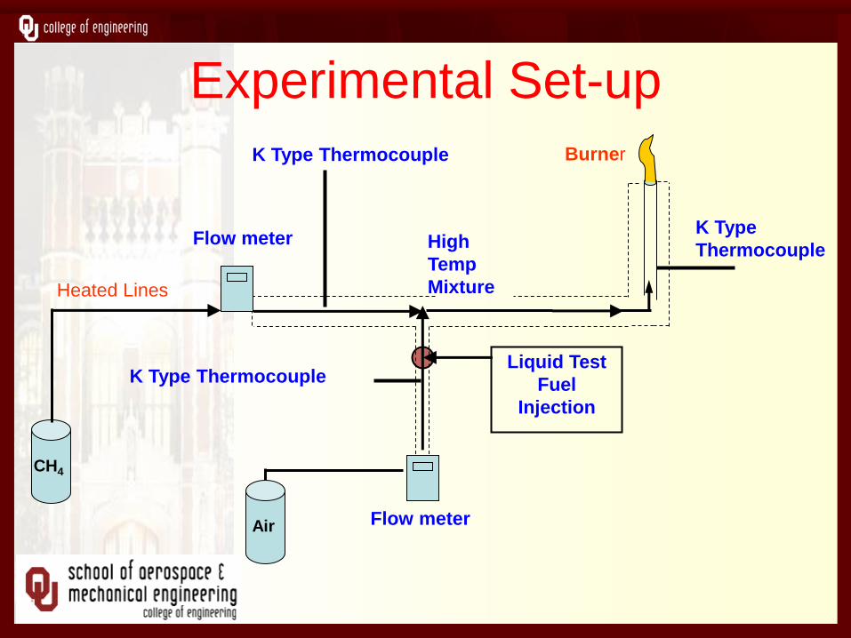
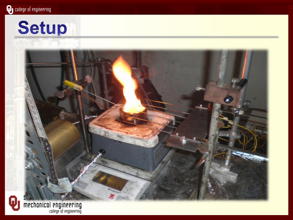
Experimental Set-up
Heated Lines
CH4
High
Temp
Mixture
Burner
K Type
Thermocouple Flow meter
K Type Thermocouple
K Type Thermocouple
Flow meter
Liquid Test
Fuel
Injection
Air
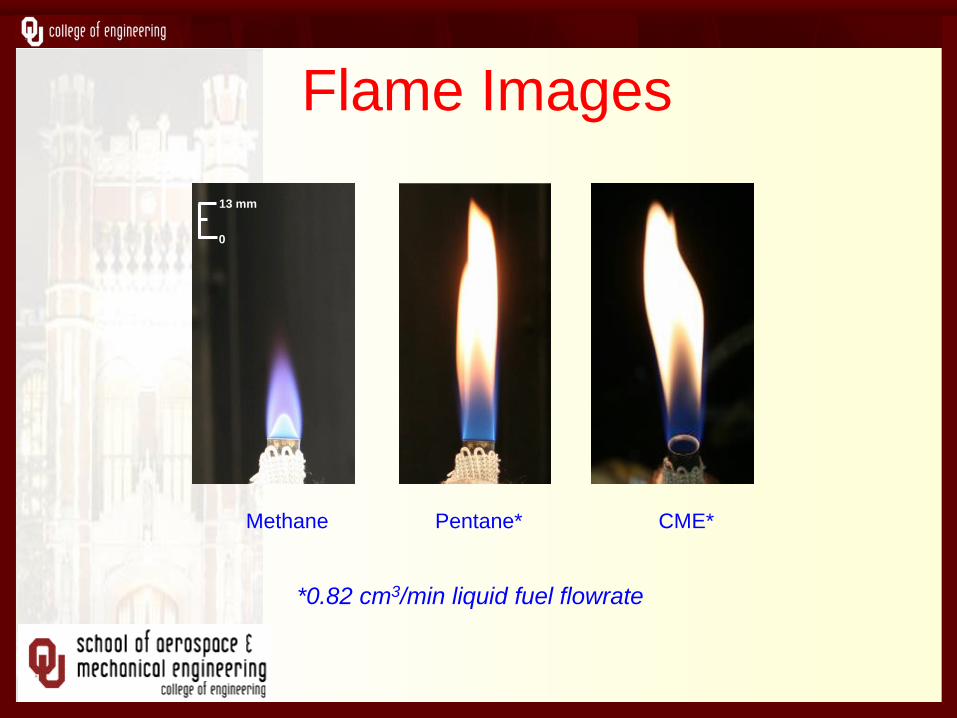
Flame Images
Methane Pentane*
*0.82 cm3/min liquid fuel flowrate
0
13 mm
CME*
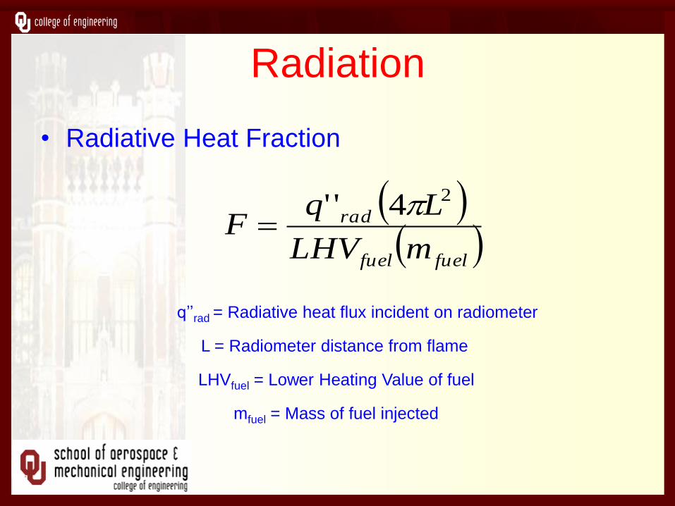
Radiation
• Radiative Heat Fraction
fuelfuel
rad
mLHV
LqF
24''
q’’rad = Radiative heat flux incident on radiometer
L = Radiometer distance from flame
LHVfuel = Lower Heating Value of fuel
mfuel = Mass of fuel injected

Radiation Results
0
0.1
0.2
0.3
0.4
0.5
Toluen
e
Die
sel
CM
E B
100
Ker
osen
e
Met
hanol
Pen
tane
Hex
ane
Hep
tane
Dod
ecan
e
Ra
dia
tiv
e F
rac
tio
n o
f H
ea
t R
ele
as
e
0.82 cc/min
1.60 cc/min
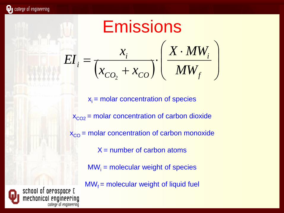
Emissions
xi = molar concentration of species
xCO2 = molar concentration of carbon dioxide
xCO = molar concentration of carbon monoxide
X = number of carbon atoms
MWi = molecular weight of species
MWf = molecular weight of liquid fuel
f
i
COCO
ii
MW
MWX
xx
xEI
2
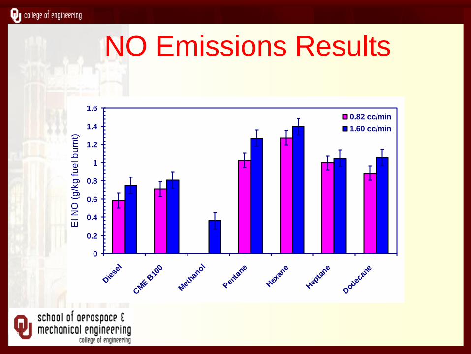
NO Emissions Results
0
0.2
0.4
0.6
0.8
1
1.2
1.4
1.6
Die
sel
CM
E B
100
Met
hanol
Pen
tane
Hex
ane
Hep
tane
Dod
ecan
e
EI N
O (
g/k
g fu
el b
urn
t)
0.82 cc/min
1.60 cc/min
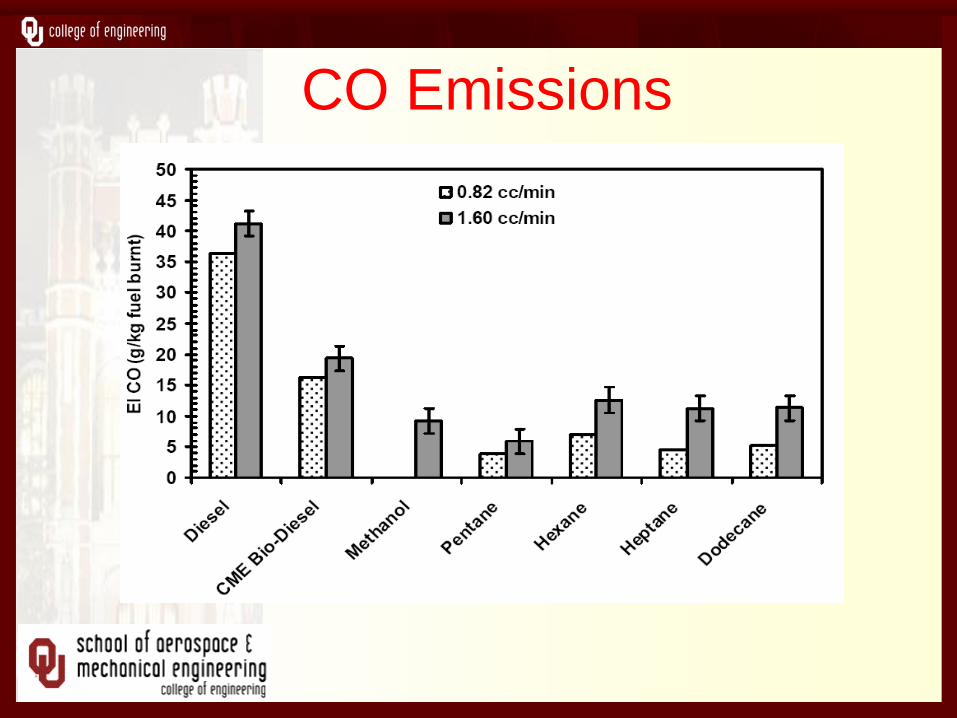
CO Emissions
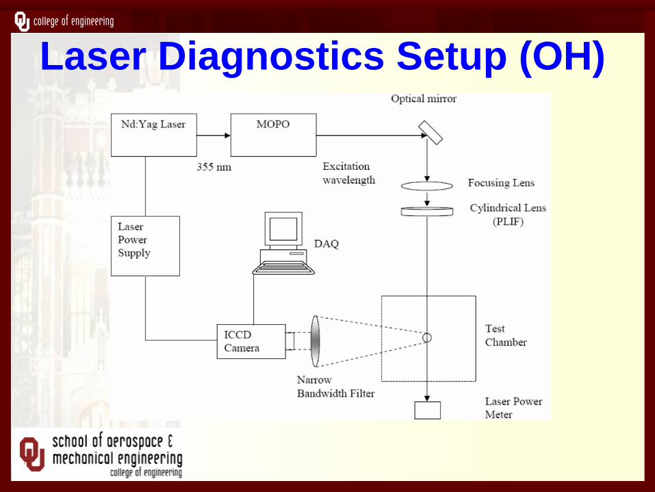
Laser Diagnostics Setup (OH)
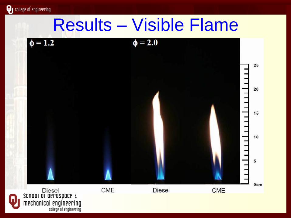
Results – Visible Flame
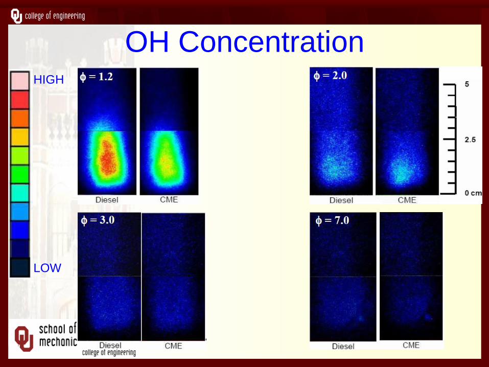
OH Concentration
LOW
HIGH
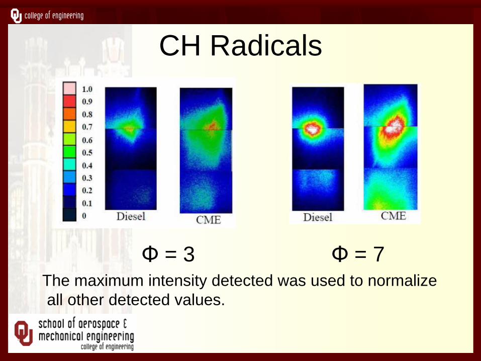
CH Radicals
Φ = 3 Φ = 7 The maximum intensity detected was used to normalize
all other detected values.
B. Spray Studies
• Atomization
• Combustion
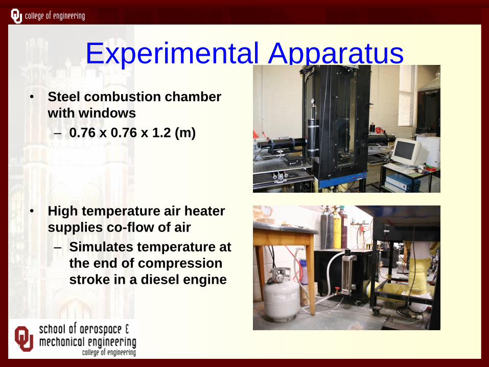
Experimental Apparatus
• Steel combustion chamber
with windows
– 0.76 x 0.76 x 1.2 (m)
• High temperature air heater
supplies co-flow of air
– Simulates temperature at
the end of compression
stroke in a diesel engine

Instrumentation • Aerometrics Phase Doppler Particle Analyzer
• Measurements of axial velocity and droplet diameter
are made non- intrusively using Doppler effect.
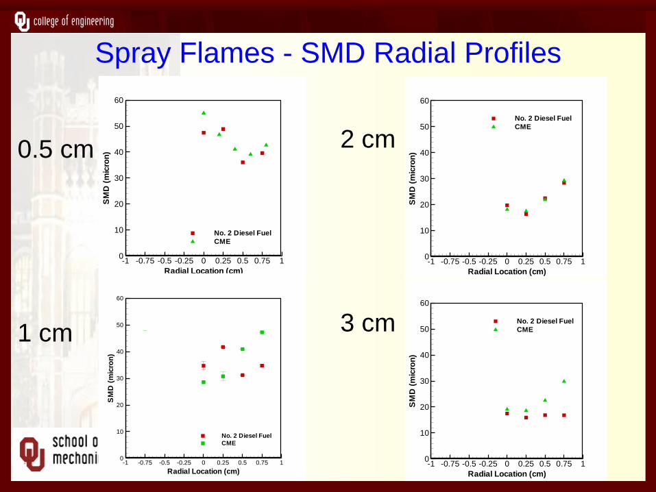
Spray Flames - SMD Radial Profiles
2 cm
3 cm
Radial Location (cm)
SM
D(m
icro
n)
-1 -0.75 -0.5 -0.25 0 0.25 0.5 0.75 10
10
20
30
40
50
60
No. 2 Diesel Fuel
CME
Radial Location (cm)
SM
D(m
icro
n)
-1 -0.75 -0.5 -0.25 0 0.25 0.5 0.75 10
10
20
30
40
50
60
No. 2 Diesel Fuel
CME
0.5 cm
1 cm
Radial Location (cm)
SM
D(m
icro
n)
-1 -0.75 -0.5 -0.25 0 0.25 0.5 0.75 10
10
20
30
40
50
60
No. 2 Diesel Fuel
CME
Radial Location (cm)
SM
D(m
icro
n)
-1 -0.75 -0.5 -0.25 0 0.25 0.5 0.75 10
10
20
30
40
50
60
No. 2 Diesel Fuel
CME
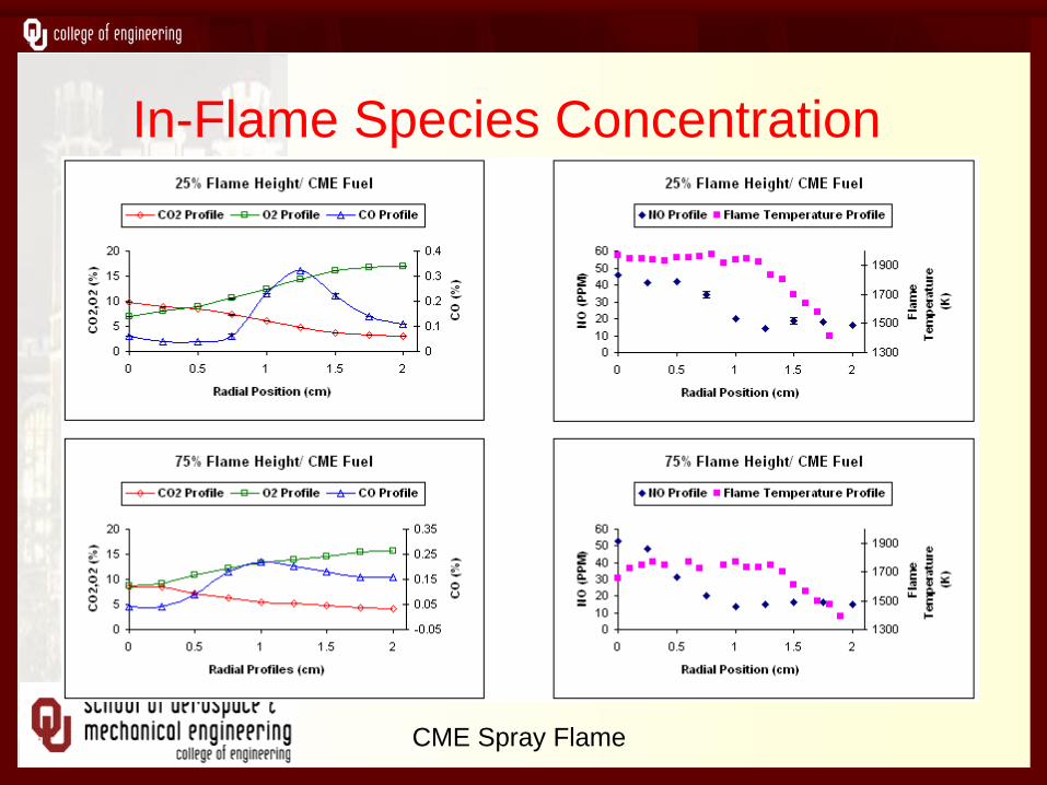
In-Flame Species Concentration
Profiles
CME Spray Flame
C1. Diesel Engine Studies
• Performance
• Emissions
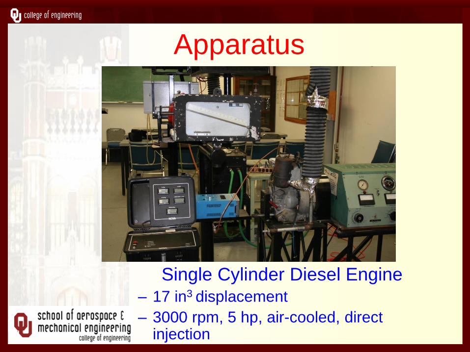
Apparatus
Single Cylinder Diesel Engine – 17 in3 displacement
– 3000 rpm, 5 hp, air-cooled, direct injection
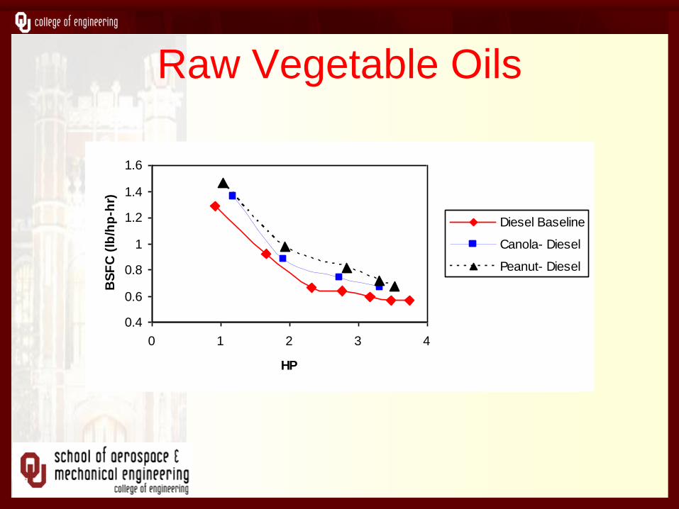
Raw Vegetable Oils
0.4
0.6
0.8
1
1.2
1.4
1.6
0 1 2 3 4
HP
BS
FC
(lb
/hp
-hr)
Diesel Baseline
Canola- Diesel
Peanut- Diesel
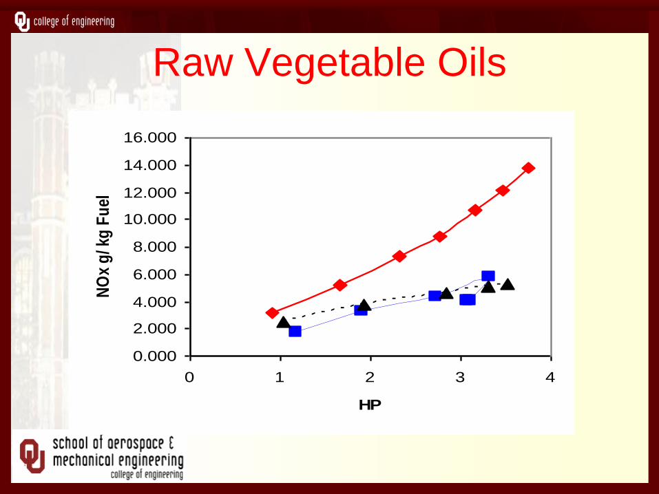
Raw Vegetable Oils
0.000
2.000
4.000
6.000
8.000
10.000
12.000
14.000
16.000
0 1 2 3 4
HP
NO
x g
/ kg
Fu
el
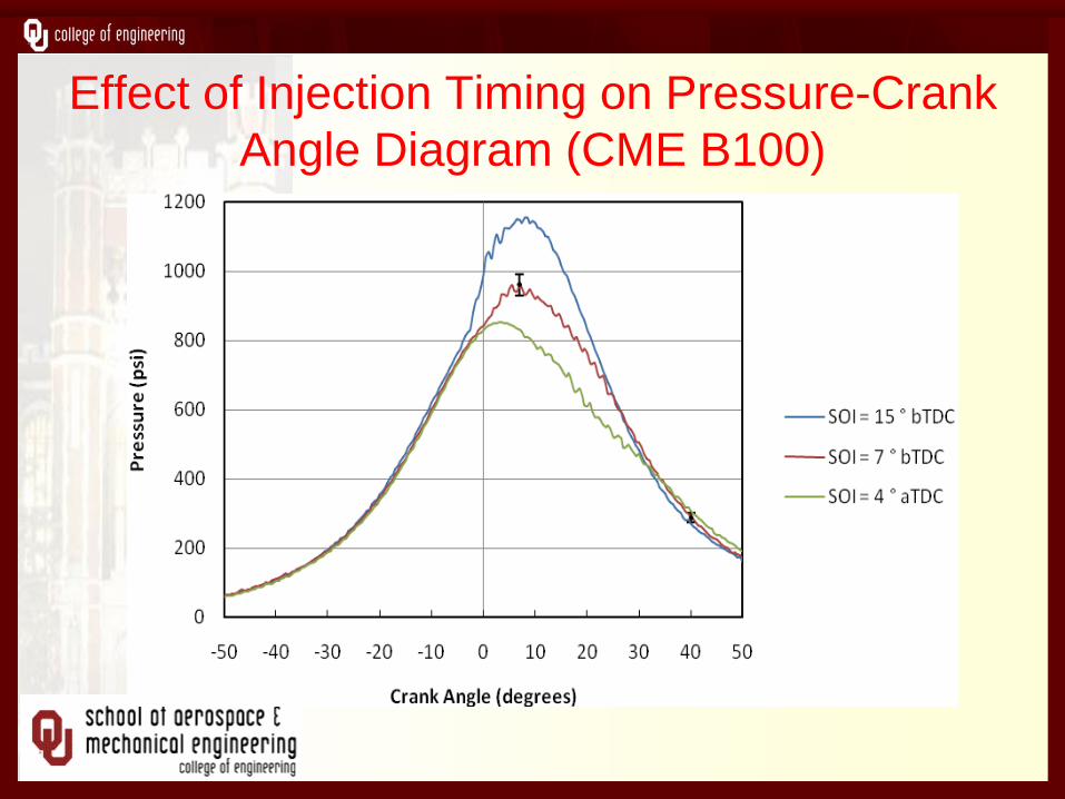
Effect of Injection Timing on Pressure-Crank
Angle Diagram (CME B100)
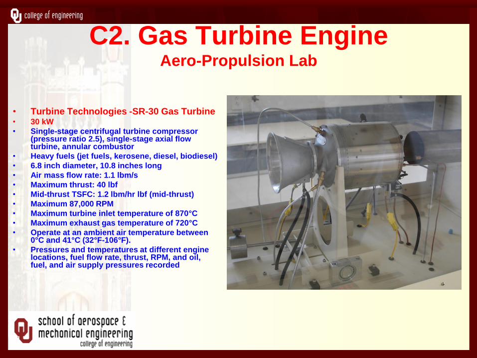
C2. Gas Turbine Engine Aero-Propulsion Lab
• Turbine Technologies -SR-30 Gas Turbine • 30 kW
• Single-stage centrifugal turbine compressor (pressure ratio 2.5), single-stage axial flow turbine, annular combustor
• Heavy fuels (jet fuels, kerosene, diesel, biodiesel)
• 6.8 inch diameter, 10.8 inches long
• Air mass flow rate: 1.1 lbm/s
• Maximum thrust: 40 lbf
• Mid-thrust TSFC: 1.2 lbm/hr lbf (mid-thrust)
• Maximum 87,000 RPM
• Maximum turbine inlet temperature of 870°C
• Maximum exhaust gas temperature of 720°C
• Operate at an ambient air temperature between 0°C and 41°C (32°F-106°F).
• Pressures and temperatures at different engine locations, fuel flow rate, thrust, RPM, and oil, fuel, and air supply pressures recorded

Experimental Results
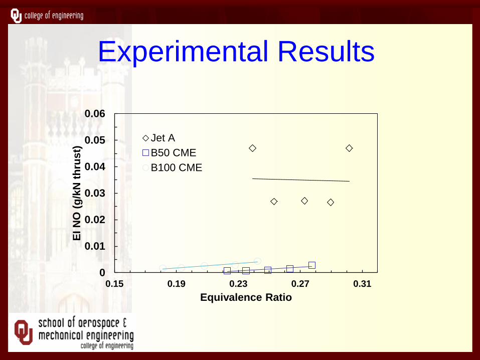
Experimental Results
0
0.01
0.02
0.03
0.04
0.05
0.06
0.15 0.19 0.23 0.27 0.31
EI N
O (
g/k
N t
hru
st)
Equivalence Ratio
Jet A
B50 CME
B100 CME
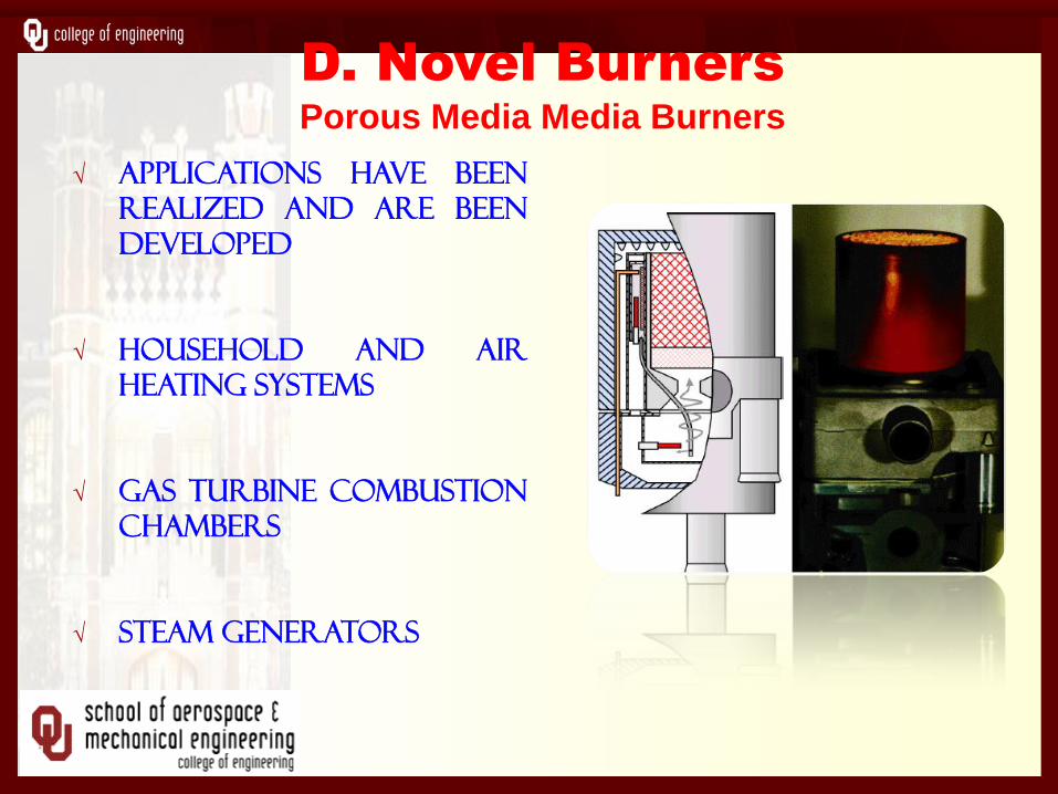
√ Applications have been
realized and are been
developed
√ Household and air
heating systems
√ Gas turbine combustion
chambers
√ Steam generators
D. Novel Burners
Porous Media Media Burners
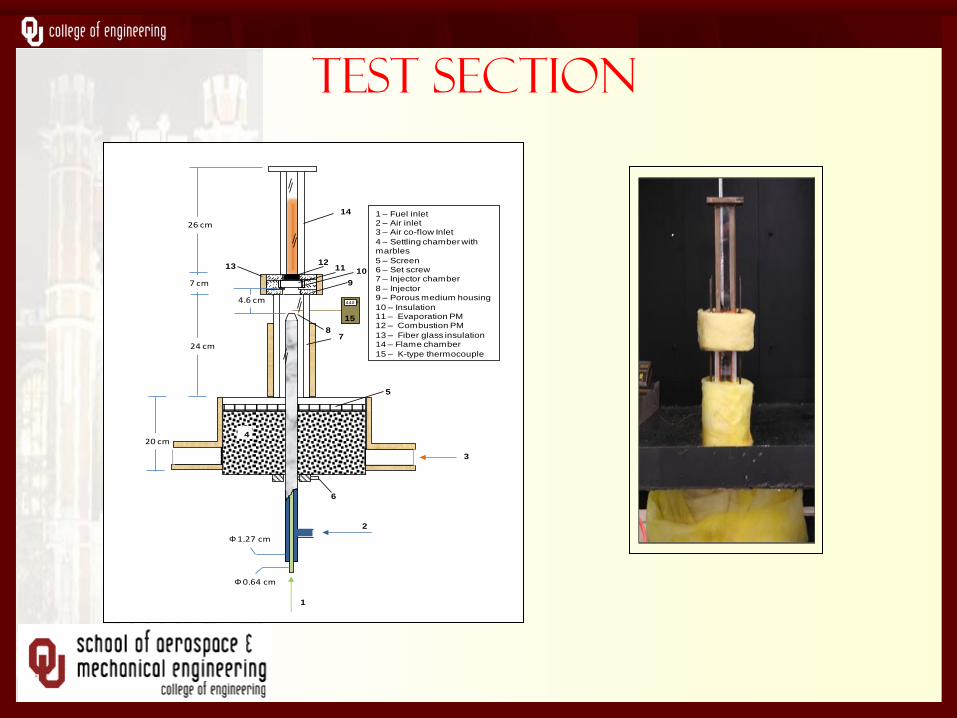
Test section
Ф1.27 cm
Ф0.64 cm
1012
11
1
2
4
5
3
9
6
1 – Fuel inlet2 – Air inlet3 – Air co-flow Inlet
4 – Settling chamber with marbles
5 – Screen6 – Set screw7 – Injector chamber
8 – Injector 9 – Porous medium housing
10 – Insulation11 – Evaporation PM 12 – Combustion PM
13 – Fiber glass insulation14 – Flame chamber
15 – K-type thermocouple
7 cm
26 cm
24 cm
4.6 cm
20 cm
87
13
14
440 F
15
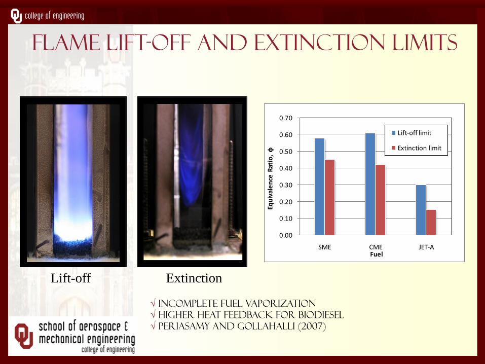
FLAME LIFT-OFF AND EXTINCTION LIMITS
0.00
0.10
0.20
0.30
0.40
0.50
0.60
0.70
SME CME JET-A
Equ
ival
en
ce R
atio
, ф
Fuel
Lift-off limit
Extinction limit
Lift-off Extinction
√ Incomplete fuel vaporization
√ Higher heat feedback for biodiesel
√ Periasamy and Gollahalli (2007)
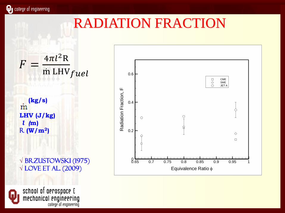
RADIATION FRACTION
Equivalence Ratio
Rad
iatio
nF
ractio
n,F
0.65 0.7 0.75 0.8 0.85 0.9 0.95 10
0.2
0.4
0.6
CME
SME
JET A
(kg/s)
LHV (J/kg)
l (m)
R (W/m2)
√ Brzustowski (1975)
√ Love et al. (2009)
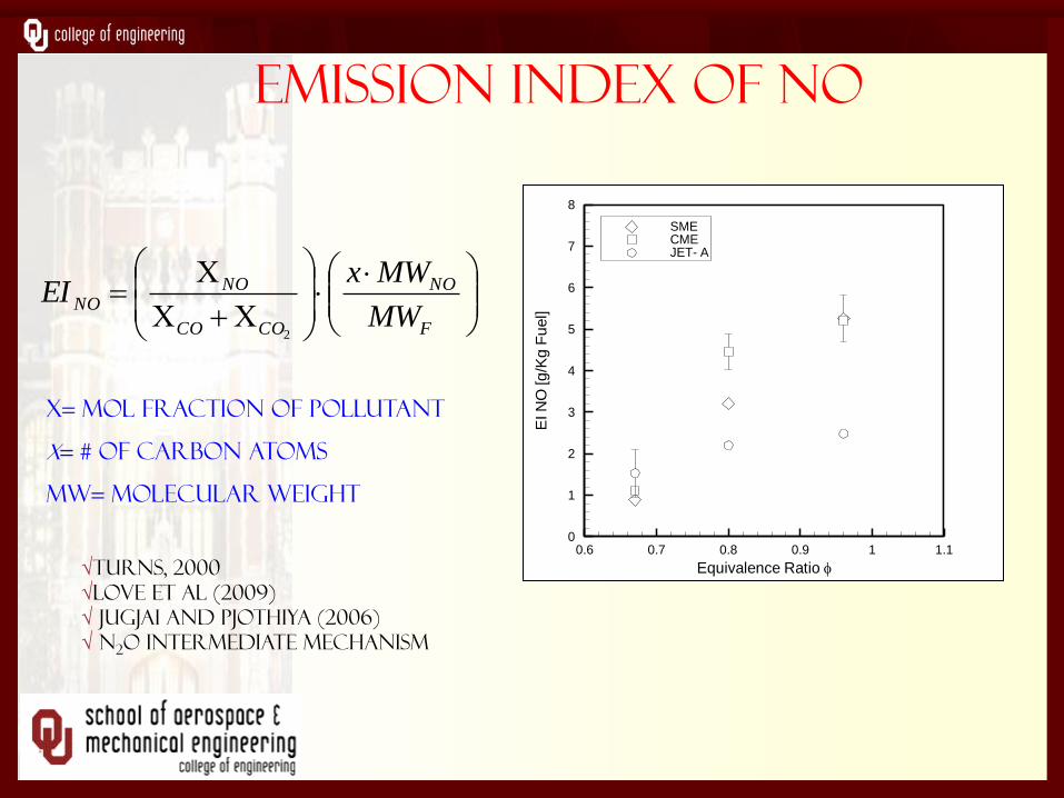
EMISSION INDEX OF NO
Equivalence Ratio
EIN
O[g
/Kg
Fu
el]
0.6 0.7 0.8 0.9 1 1.10
1
2
3
4
5
6
7
8
SMECMEJET- A
F
NO
COCO
NONO
MW
MWxEI
2
X= Mol fraction of pollutant
x= # of carbon atoms
MW= Molecular weight
√Turns, 2000
√Love et al (2009)
√ jugjai and pjothiya (2006)
√ N2O intermediate mechanism
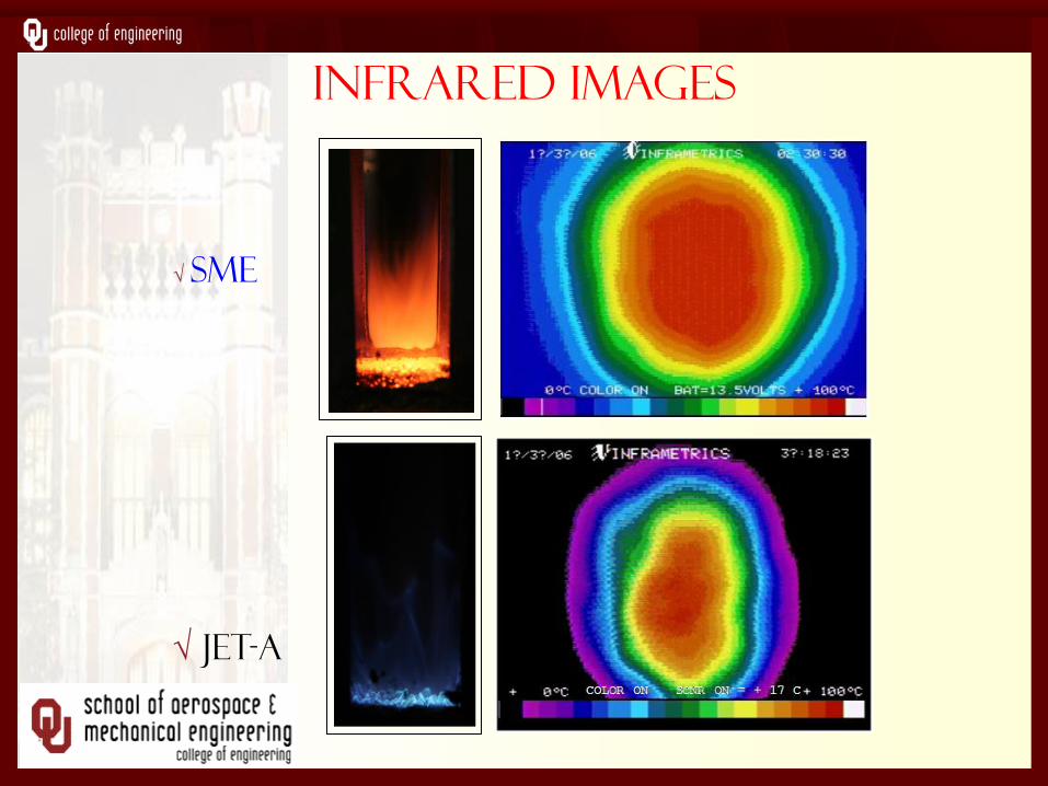
Infrared images
√ Sme
√ jet-a
E. Biofuel Fire Research
• Handling, Transportation, and Safety of
Biofuels not Understood
• Existing Literature limited to Petroleum
Pool Fires.
• Flash and Fire Points data are scanty.
• Flammability, Ignition, and Extinction are
Characteristics not known.
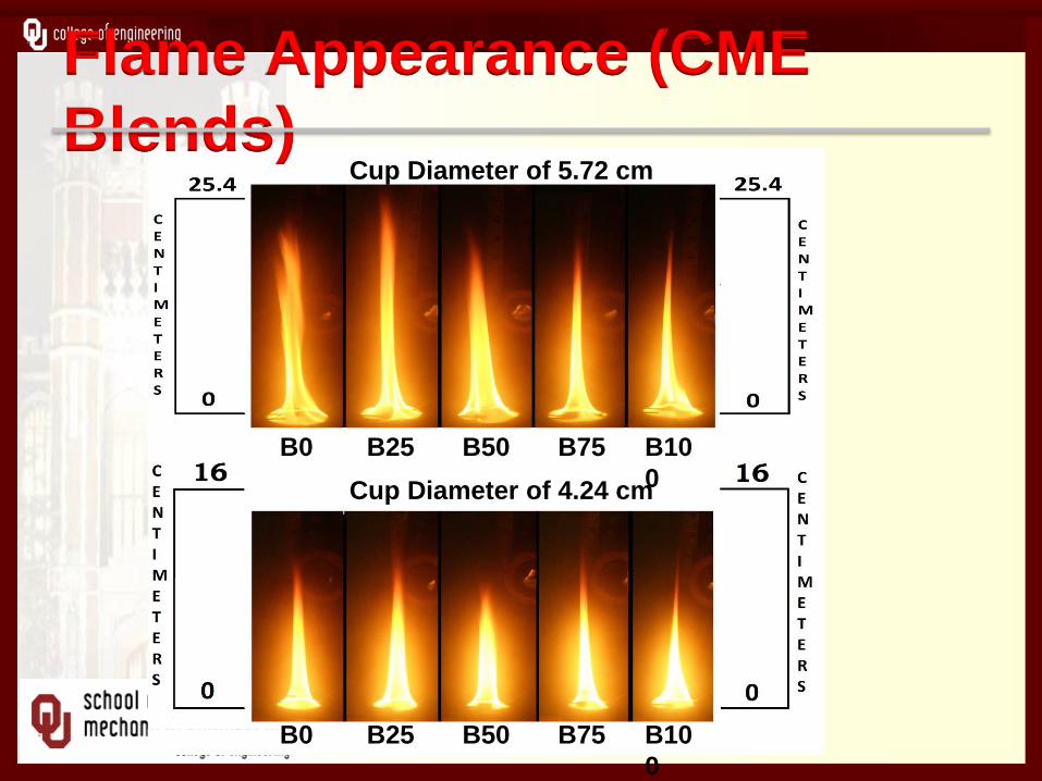
Flame Appearance (CME
Blends)
Cup Diameter of 4.24 cm
Cup Diameter of 5.72 cm
B0 B25 B50 B75 B10
0
B0 B25 B50 B75 B10
0
0
10
20
30
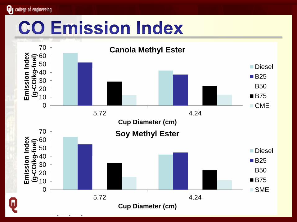
40
50
60
70
5.72 4.24
Em
issio
n I
nd
ex
(
g-C
O/k
g-f
ue
l)
Cup Diameter (cm)
Canola Methyl Ester
Diesel
B25
B50
B75
CME
0
10
20
30
40
50
60
70
5.72 4.24
Em
issio
n I
nd
ex
(g-C
O/k
g-f
ue
l)
Cup Diameter (cm)
Soy Methyl Ester
Diesel
B25
B50
B75
SME
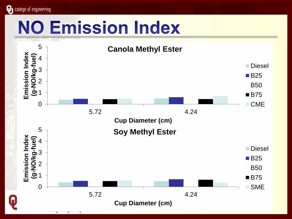
0
1
2
3
4
5
5.72 4.24
Em
issio
n I
nd
ex
(
g-N
O/k
g-f
ue
l)
Cup Diameter (cm)
Canola Methyl Ester
Diesel
B25
B50
B75
CME
0
1
2
3
4
5
5.72 4.24
Em
issio
n I
nd
ex
(
g-N
O/k
g-f
ue
l)
Cup Diameter (cm)
Soy Methyl Ester
Diesel
B25
B50
B75
SME

THANK YOU