aero 40 jet manua… · · 2012-12-11• never exceed recommended hose or blasting unit pressure...
TRANSCRIPT

Operator Manual
Aero 40
This manual illustrates the safety, operation, and
maintenance features of the Cold Jet Aero 40.
The build and revision level is located on the machine’s data plate.
The design contained in this manual was originated
by and is the exclusive property of Cold Jet, LLC. It is
not to be used in any way detrimental to the interests
of Cold Jet, LLC.
No part of this design or manual may be reproduced,
transmitted, stored in a retrieval system, or translated
into any other language or computer language,
in whole or in part, in any form or by any means,
whether electronic, mechanical, magnetic, optical,
manual or other, without the express written consent
of Cold Jet, LLC.
Copyright 2008 Cold Jet, LLC All Rights Reserved Printed in U.S.A.
Special Notes
All information contained within this manual,
or information derived from exposure to the
technology or equipment supplied by Cold Jet,
LLC remains “CONFIDENTIAL” between Cold Jet,
LLC and the purchaser or authorized user. Any
unauthorized transfer of information to any person
or company not in the direct employ of Cold Jet,
LLC, or not in the direct employ of the purchaser or
the authorized user, is strictly prohibited.
Model No. 40
Ae
ro 4
0

Table of Contents
SafetyGeneral Safety Precautions 6
Electrostatic Discharge 7
Carbon Dioxide 8
Machine Safety 9
Get to Know your MachineFront View 12
Rear View 13
Control Panel 14
Blast Applicator 15
OperationStart Up 18
Shut Down 19
MaintenanceTroubleshooting 22
Maintenance 23
AppendixSpecificationsSymbol Glossary
2627
Blast Air Quality 29
Warranty 31
Customer Service 33
Training Video 34

Aero 40
SafetyGeneral Safety Precautions
Electrostatic Discharge
Carbon Dioxide
Machine Safety
6
7
8
9

6
• NEVER use a wire tie to hold the applicator trigger in the ON position. (Doing so violates safety regulations, can damage applicator, and voids warranty coverage of applicator.)
• ALWAYS turn source air OFF and remove the applicator control line before removing the blast hose.
• ALWAYS follow the guidelines of the governing codes of your local/national body.
• NEVER DISCONNECT the air supply hose without first shutting off the source air and bleeding down the system.
• ALWAYS WEAR safety glasses, gloves, 32+NRR ear plugs & ear muffs.
• NEVER OPERATE the unit without first reading the Operator Manual.
• NEVER exceed recommended hose or blasting unit pressure levels.
• DO NOT ever kink the blast hose.
• ALWAYS ENSURE that hoses are securely tightened.
• ALWAYS electrostatic ground the material being cleaned.
• CHECK hoses and tubes for nicks and gouges.
• NEVER OPERATE a damaged blasting system.
• NEVER mask the ventilation holes.
General Safety Precautions
7
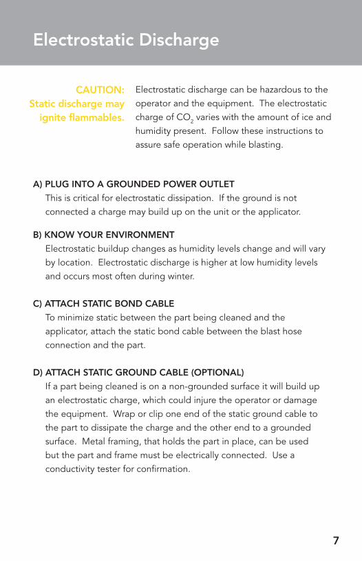
A) PLUG INTO A GROUNDED POWER OUTLET
This is critical for electrostatic dissipation. If the ground is not connected a charge may build up on the unit or the applicator.
B) KNOW YOUR ENVIRONMENT
Electrostatic buildup changes as humidity levels change and will vary by location. Electrostatic discharge is higher at low humidity levels and occurs most often during winter.
C) ATTACH STATIC BOND CABLE
To minimize static between the part being cleaned and the applicator, attach the static bond cable between the blast hose connection and the part.
D) ATTACH STATIC GROUND CABLE (OPTIONAL)
If a part being cleaned is on a non-grounded surface it will build up an electrostatic charge, which could injure the operator or damage the equipment. Wrap or clip one end of the static ground cable to the part to dissipate the charge and the other end to a grounded surface. Metal framing, that holds the part in place, can be used but the part and frame must be electrically connected. Use a conductivity tester for confirmation.
Electrostatic Discharge
Electrostatic discharge can be hazardous to the operator and the equipment. The electrostatic charge of CO2 varies with the amount of ice and humidity present. Follow these instructions to assure safe operation while blasting.
CAUTION: Static discharge may
ignite flammables.

8
Carbon Dioxide Safety Precautions
• This unit utilizes solid state Carbon Dioxide (Dry Ice) as a blast media.
• Dry Ice is very cold ( -110° F / -79° C ) and may freeze skin instantly.
• CO2 is heavier than air, which means it will settle to the ground.
• Always ventilate when blasting.
• CO2 is nontoxic, non-corrosive, non-conductive and is approved by the FDA and USDA. While exposure to CO2 gas is not harmful in low concentrations, CAUTION should be exercised when using any material that can DISPLACE OXYGEN.
• Please refer to Carbon Dioxide (CO2) MSDS sheet for all safety precautions. (available from dry
ice supplier.)
ASPHYXIATION HAZARD
Increased levels of CO2 when blasting in a confined space can displace breathable oxygen creating a risk of serious injury or death, therefore use of a carbon dioxide monitoring device is required when using in a confined space.
BURN HAZARD
Do not allow skin to directly contact dry ice. Always use protective clothing (Thermal Gloves) and eye protection when handling CO2 solids or when using the blasting unit.
Carbon Dioxide (CO2) is a naturally
occurring non-toxic gas, however caution should be
exercised.
9
A) ERGONOMICS
CO2 blasting involves direct discharge of an air powered blasting nozzle. The operator experiences a reactive thrust which increases with blast pressure and air flow. Operator fatigue may become a concern depending on issues such as blasting angle, work area, temperature, operator strength and level of physical conditioning. Do not exceed allowable limits of blast pressure, duty cycle and total blast time as determined by on site health and safety personnel knowledgeable about site-specific conditions and available worker population.
B) LOCK OUT/TAG OUT WARNING
Do not attempt any maintenance procedure unless all input electrical and air sources are locked out and tagged out according to applicable regulations.
Machine Safety

Aero 40
Get to Know Your Machine
Front View 12
Rear View 13
Control Panel 14
Blast Applicator 15
12
C
Bleed ValveC
A
B
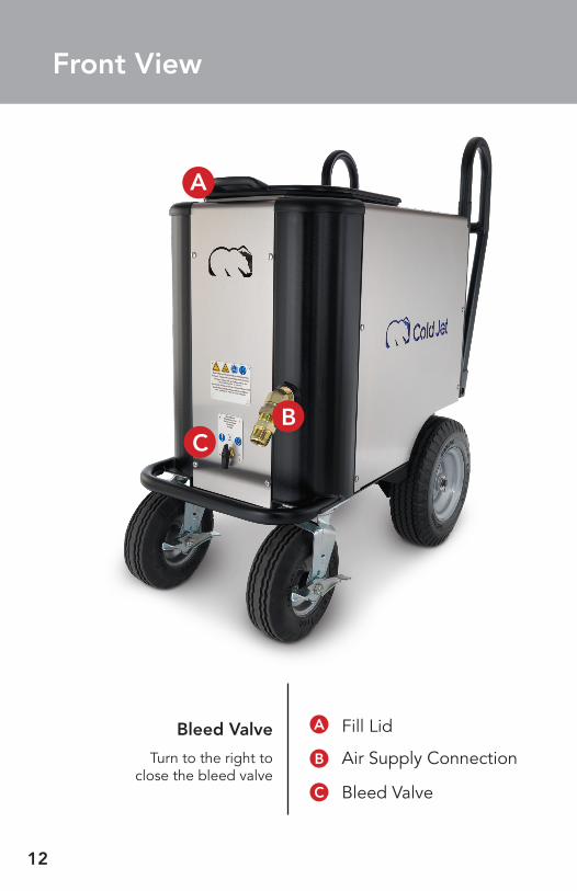
Fill Lid
Air Supply Connection
Front View
Bleed Valve
Turn to the right to close the bleed valve
A
B
13
D
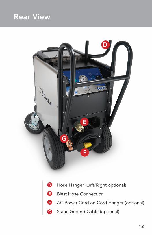
Rear View
D
E
CF
G
Hose Hanger (Left/Right optional)
Blast Hose Connection
AC Power Cord on Cord Hanger (optional)
Static Ground Cable (optional)
E
F
G
14
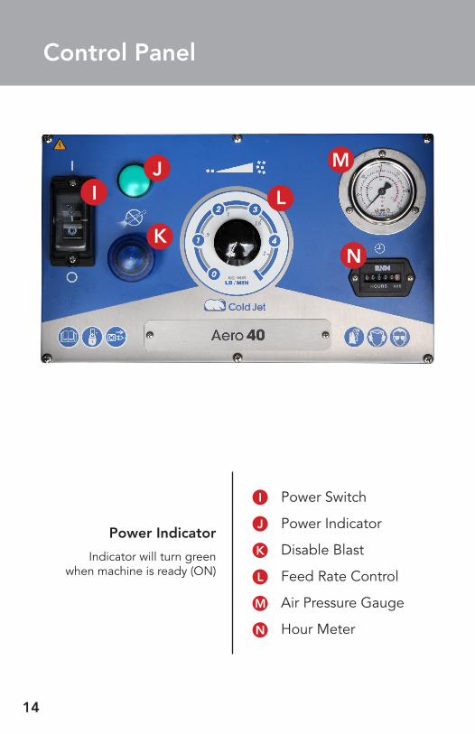
Control Panel
CN
Power Switch
Power Indicator
Disable Blast
Feed Rate Control
Air Pressure Gauge
Hour Meter
Power Indicator
Indicator will turn green when machine is ready (ON)
I
J
K
L
M
CJCI
K
L
M
N
15
O
CP
CQ
CT
R
S U
Q
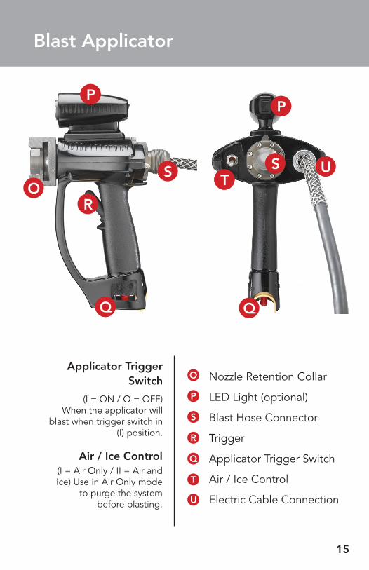
Nozzle Retention Collar
LED Light (optional)
Blast Hose Connector
Trigger
Applicator Trigger Switch
Air / Ice Control
Electric Cable Connection
Applicator Trigger Switch
(I = ON / O = OFF)When the applicator will
blast when trigger switch in (I) position.
Air / Ice Control(I = Air Only / II = Air and Ice) Use in Air Only mode
to purge the system before blasting.
Blast Applicator
U
T
O
P
S
R
Q
S
CP

Aero 40
Start Up 18
Shut Down 19Operation
18
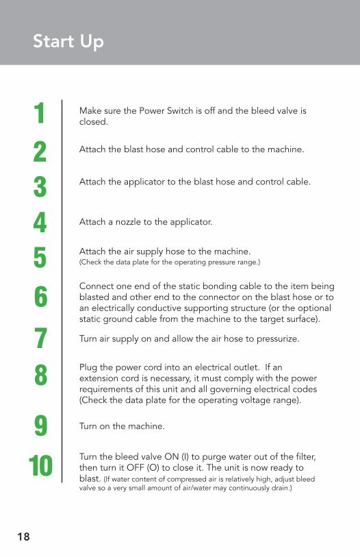
Start Up
Make sure the Power Switch is off and the bleed valve is closed.
Attach the blast hose and control cable to the machine.
Attach the applicator to the blast hose and control cable.
Attach a nozzle to the applicator.
Attach the air supply hose to the machine. (Check the data plate for the operating pressure range.)
Connect one end of the static bonding cable to the item being blasted and other end to the connector on the blast hose or to an electrically conductive supporting structure (or the optional static ground cable from the machine to the target surface).
Turn air supply on and allow the air hose to pressurize.
123456
78
910 Turn the bleed valve ON (I) to purge water out of the filter,
then turn it OFF (O) to close it. The unit is now ready to blast. (If water content of compressed air is relatively high, adjust bleed valve so a very small amount of air/water may continuously drain.)
Turn on the machine.
Plug the power cord into an electrical outlet. If an extension cord is necessary, it must comply with the power requirements of this unit and all governing electrical codes (Check the data plate for the operating voltage range).
19
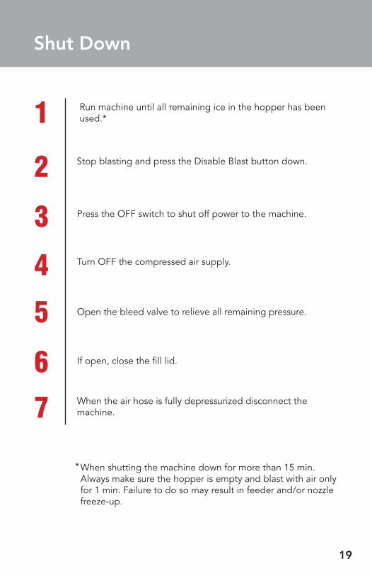
Shut Down
Stop blasting and press the Disable Blast button down.
1 Run machine until all remaining ice in the hopper has been used.*
2
Turn OFF the compressed air supply.
3 Press the OFF switch to shut off power to the machine.
4Open the bleed valve to relieve all remaining pressure.5If open, close the fill lid.6When the air hose is fully depressurized disconnect the machine.7
When shutting the machine down for more than 15 min. Always make sure the hopper is empty and blast with air only for 1 min. Failure to do so may result in feeder and/or nozzle freeze-up.
*
Aero 40

Maintenance Troubleshooting 22
Maintenance 23

22
Troubleshooting
PROBLEM CHECK THIS SOLUTION
Machine will NOT start
(GREEN light is not on)
Is the unit plugged in? If NO...Plug Unit in.
Is the power switch in the I position?
If NO...Push power switch to I.
It still will not start? Call Cold Jet for support.
Machine will NOT blast
Is the machine active light (the GREEN light) on?
If NO...Reset the disable blast button.If the above does not work then call Cold Jet for support.
Is the applicator safety switch pushed back? (Safety ON) (O).
If YES...Flip the switch forward (Safety OFF) ( I ).
Is the air supply connected and the air supply on?
If YES...The nozzle may be clogged, blast with air only to unclog the nozzle.
Is the air supply gauge showing pressure?
Is the optional pressure regulator open and displaying pressure?
Is the applicator cable connected to the machine and the applicator?
Machine blasts AIR but NOT pellets
Is the feed rate adjusted? Turn up the feed rate
Is the Hopper clogged?If YES...call Cold Jet for support.
Is applicator Air/Ice control in the ( II ) position?
If YES...call Cold Jet for support.
Is a foreign object lodged in the feeder assembly?
If YES...call Cold Jet for support.

23
DAILY
WEEKLY
MONTHLY
BIANNUAL
• Drainwateroutoftheairfilterbefore using the machine. • Whileinoperationcheckthepressure
gauge for damage.• Checktheairandblasthosesfor damage (ie: cuts or scuff marks).
• Lookthroughthehoppertocheckthe rotor for nicks or gouges. • Makesurethenozzleairflowexitendis not deformed or burred.
• Checktheairfilterbyunscrewingthe base a 1/4 turn clockwise.
• Checkpneumaticairlines• Checkstaticgroundcable&reel• Checktheaccessories• Checkallvalves• Safetytesttheunit• Checkthumper• Inspecthosesfordamage• Checkthepressuregauge
Maintenance

Aero 40

Appendix
Specifications 26
Symbol Glossary
Blast Air QualityWarranty
27
3031
Customer Service 33
Training Video 34
26
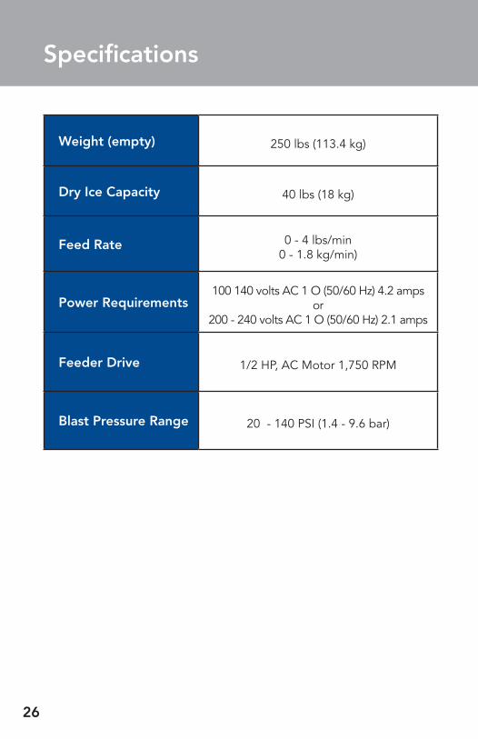
Specifications
Weight (empty) 250 lbs (113.4 kg)
Dry Ice Capacity 40 lbs (18 kg)
Feed Rate 0 - 4 lbs/min0 - 1.8 kg/min)
Power Requirements100 140 volts AC 1 O (50/60 Hz) 4.2 amps
or 200 - 240 volts AC 1 O (50/60 Hz) 2.1 amps
Feeder Drive 1/2 HP, AC Motor 1,750 RPM
Blast Pressure Range 20 - 140 PSI (1.4 - 9.6 bar)

27
General Danger Variable feed
Electric Shock or Electrocution Enable Blasting
Extreme Cold Disable Blasting
Hand Crush from Side Wear Ear Protection
Hand Cut from Impeller Blade Wear Eye Protection
Flying Debris Read Operator Manual
Skin Puncture from Pressurized Air Jet Wear Safety Gloves
Loud Noise General Mandatory Action
Explosive Release of Pressure
Maintain Safe Pressure
Air Bleed Do Not Operate with Guard removed
CO2 Only No Foreign Objects
Symbol Glossary

28
Symbol Glossary (cont.)
Refer to Manual
Lock Out/ Tag Out Before Servicing
Disconnect Power Before Servicing
Hour Meter
Crush Hazard
Protective Earth/Ground
Earth/Ground
I Applicator Trigger Enabled (on bottom of applicator)
I Air Only
O Applicator Trigger Disabled
II Air and Ice

29
Using Plant Air (Central Compressed Air System)Manufacturing plants, with central compressed air systems, should have an After Cooler and a 2-stage coalescing filter assembly downstream of the receiver tank. Hot metal pipes are an indication this is needed.
To verify that the plant air system is adequate for the Aero 40 the air compressor needs to produce an air volume 10% greater than the blast machine’s maximum air volume...in addition to the air volume consumed by normal plant operation.
To determine adequate air volume, watch the pressure gauge while blasting.
•Ifthegaugedropsslowlythecompressorisinsufficient.
•If the gauge drops quickly there is a restriction or the pipe is too small.
•If the gauge stays steady then the compressor and piping are adequate.
To maintain adequate pressure to the Aero 40:
•Fromtheaircompressorto50ft(15m)useaflexible1in(2.5cm)airhose (preferably the hose supplied with the machine).
•From the air compressor to beyond 50 ft (15 m) make sure the pipe is 1 in (2.5 cm) in diameter before attaching the air hose.
If an air drop isn’t used much, water and rust will collect in the line. Before plugging into the air supply, purge the line, to prevent contamination of the Aero 40.
Using Portable Air (minimum of 185 cfm - 5.6 m3/min)Portable diesel air compressors are frequently not optimized for dry ice blasting units and are therefore not configured to cool or remove air moisture.The Cold Jet After Cooler is required to reduce the discharge
Blast Air Quality
Refer to Manual
Lock Out/ Tag Out Before Servicing
Disconnect Power Before Servicing
Hour Meter
Crush Hazard
Protective Earth/Ground
Earth/Ground
I Applicator Trigger Enabled (on bottom of applicator)
I Air Only
O Applicator Trigger Disabled
II Air and Ice

30
air temperature 180°F (82°C) to within 15°F (-9°C) of ambient air temperature. Visit www.coldjet.com to learn more about purchasing a Cold Jet After Cooler.
Without the After Cooler, the following will occur:
1. Incoming air moisture may rapidly cool and freeze at the Aero 40 feeder.
2. Water ice may accumulate in the feeder, distorting the air flow and seal.
3. Water ice buildup may continue inside the blast hose, to the nozzle.
4. Water ice may break off inside the hose and lodge in the nozzle, causing a jam.
5. Water ice, may exit the nozzle, and damage the target surface.
If blasting continuously, an air dryer will further reduce the air moisture (dew point). Desiccant dryers produce a dew point of -40°F (-40°C), resulting in a dew point low enough for continuous blasting.
To verify the compressor is of adequate size for the Aero 40, the air compressor needs to produce an air volume 10% greater than the blast system’s maximum required air volume.
To determine adequate air volume, blast while watching the pressure gauge.
•Ifthegaugedropsslowlythecompressorisinsufficient.
•Ifthegaugedropsquicklythereisarestrictionorthepipeistoosmall.
•Ifthegaugestayssteadythenthecompressorisadequate.
To maintain adequate pressure, the hose size from the compressor to the blast system needs to be a minimum of 1 in (2.5 cm) in diameter.
31
Cold Jet® (“CJ”) warrants its products (“Equipment”) provided under this
Agreement to be free from defects in materials and workmanship for a period
of 12 months, under normal use, maintenance and service as stipulated in the
Operator’s Manual. CJ warrants that the equipment will be in good work-
ing order on the Date of Shipment and will conform to CJ’s official published
specifications.
The warranty period is 12 months for CJ manufactured Equipment. Original
Equipment Manufacturers’ warranties provided by CJ on equipment purchased
under this Agreement not manufactured by CJ will be passed through to
the Buyer. The warranty period commences on the Date of Shipment of the
Equipment.
CJ’s liability is limited to repairing or replacing, at its option, any covered part
of its Equipment, which CJ has determined to be defective. Said repair or
replacement will be made by CJ or its authorized representative free of charge
to the Buyer, except for any freight or travel expenses, during the warranty
period. Any replaced part will become the property of CJ. If, after repeated
efforts, CJ is unable to restore its Equipment to good working order, or to
replace the defective parts as warranted, CJ may, at its discretion, replace the
Equipment in its entirety. Any claim must be made to CJ, in writing, within 30
days of discovering the defect and any claim not made within that period shall
be deemed waived or released, and thus denied.
Warranty service provided under this Agreement does not assume
uninterrupted operation of the Equipment. The suitability of the equipment
for the purpose intended is not included in the warranty.
Warranty Information
32
This warranty shall not apply and CJ shall be neither responsible nor liable for:
a) Consequential, collateral or special losses or damages;
b) Equipment conditions caused by abnormal conditions of use, accident, neglect or misuse of equipment, improper storage or damages resulting during shipment as determined by CJ;
c) The replacement of normal wear items, including but not limited to air, blast and whip end hoses;
d) Deviation from the Equipment’s prescribed maintenance programs, replacement parts, operating instructions, specifications or other terms of sale;
e) Labor charges, loss or damage resulting from improper operation, maintenance or repairs made by person(s) other than CJ or CJ-authorized service representatives;
f) Improper application of the product. In no event shall CJ be liable for claims in excess of the purchase price, whether there is a breach of contract or warranty claim of negligence or negligent manufacture.
THIS WARRANTY IS THE SOLE WARRANTY OF CJ AND ANY OTHER WARRANTIES, EXPRESS, IMPLIED IN LAW OR IMPLIED BY FACT, INCLUDING ANY WARRANTIES OF MERCHANTABILITY AND FITNESS FOR PARTICULAR USE, ARE HEREBY SPECIFICALLY EXCLUDED.

33
Cold Jet employs an experienced customer support team
to assist you with troubleshooting, maintenance, parts and
accessories for your Aero 40.
24/7 Customer Support HOTLINE:
United States/Canada: +1.800.777.9101
Europe: +32 (0) 13 53 94 47
Office Hours: GMT +1.00
All other locations: +1.513.576.8981
Email:
United States/Canada: [email protected]
Europe: [email protected]
All other locations: [email protected]
Customer Service
General Contact Information
USA: +1.513.831.3211 +1.800.337.9423
Latin America: +52 81 14781267
Germany: +49 (0) 6551 9606.0
EU Headquarters: +32 (0) 13.53.95.47
Canada: +1.513.716.6501

34
Training Video

Visit www.coldjet.com to learn about the latest innovations from Cold Jet.