aero - · pdf fileproduction editor daniel sheldon ... jerry smith the boeing component ......
TRANSCRIPT

B O E I N G 21A E R O
N o .
Aero magazine is published quarterly by Boeing Commercial Airplanes and is distributed at no cost to operators of Boeing commercial airplanes. Aeroprovides operators with supplemental technical information to promote continuous safety and efficiency in their daily fleet operations. ■ The BoeingCompany supports operators during the life of each Boeing commercial airplane. Support includes stationing Field Service representatives in more than 60 countries, furnishing spare parts and engineering support, training flight crews and maintenance personnel, and providing operationsand maintenance publications. ■ Boeing continuously communicates with operators through such vehicles as technical meetings, service letters, and service bulletins. This assists operators in addressing regulatory requirements and Air Transport Association specifications.
Information published in Aero magazine is intended to be accurate and authoritative. However, no material should be considered FAA approved unless specifically stated. Airline personnel are advised that their company’s policy may differ from or conflict with information in this publication. Customer airlines may republish articles from Aerowithout permission if for distribution only within their own organizations. They thereby assume responsibility for the current accuracy of the republished material. All othersmust obtain written permission from Boeing before reprinting any Aero article. ■ Aero is not available by subscription. ■ Please address communications to Aero Magazine,Boeing Commercial Airplanes, P.O. Box 3707, MC 21-72, Seattle, Washington, 98124-2207, USA ■ E-mail: [email protected]
Editorial BoardRichard Breuhaus, John Cashman, Michael DiDonato, Dick Elliott, Chris Finnegan, Jeff Hawk, Al John, Bob Kelley-Wickemeyer, Elizabeth Lund, Jay Maloney, Tom Melody, John Mowery, Jerome Schmelzer, William Siegele, Roger Stropes, Bill Williams
Technical Review CommitteeFrank Billand, Richard Breuhaus, Roy Bruno, John Creighton, Edward Dobkoski, Dick Elliott, Giday Girmay, Bruce Groenewegen, Al John, Warren Lamb, Bob Manelski, Tom Melody, Doug Mohl, Norm Pauk, Gary Prescott, Jerome Schmelzer, William Siegele, William Tsai, Joan Walsh, Todd Zarfos
Boeing Model 200“Monomail”
Publisher Brian Ames
Editor-in-chief Stephen S. Szehner
Art director/designer Faye Lomax
Copy/quality editor Julie O’Donnell
Production editor Daniel Sheldon
ContributorsJulie O’DonnellEllen Whitford
Distribution managerJanet Foster
IllustratorJane Roberts
Photographers Jim AndersonKen DeJarlaisTim StakeEd Turner
Printer Graphic Arts Center
w w w . b o e i n g . c o m / a e r o m a g a z i n e
Aero is printed on recycled, recyclable paper.Copyright © 2003 The Boeing Company
AERO ONLINE

JERRY SMITH The Boeing ComponentExchange Program helps airlines reduce fleet repair expenses and inventory investment while improving schedule reliability and stabilizing long-term maintenance budget planning.
GLOBAL NAVIGATION SATELLITE SYSTEMA new positioning and landing system that integrates satellite and ground-basednavigation information improves takeoff and landing capability at reduced cost.
ERRONEOUS GLIDESLOPE Flight crews can perform glideslope confidence checks to help manage the risk of instrument landingsystems capturing erroneous glideslope signals.
747ER AND 747ER FREIGHTER The new Longer Range 747-400 airplanes offer significant range and payload improve-ments and provide greater reliability,maintainability, and flexibility.
QUIET CLIMB The Boeing Quiet ClimbSystem is a new automated avionics feature for quiet procedures that lessenscrew workload and helps airlines complywith restrictions.
747-400ER
Issue No.21FIRST-QUARTER 2003 – JANUARY Contents
19TECHNOLOGY/PRODUCT DEVELOPMENT
12SAFETY
03
PERSPECTIVE 02
TECHNOLOGY/PRODUCT DEVELOPMENT
COVER
26TECHNOLOGY/PRODUCT DEVELOPMENT

2 AERO
Three years ago, weintroduced the BoeingComponent ExchangeProgram, a servicedesigned to free car-
riers from costly fleet-support tasks without sacrificing airplaneschedule reliability. Today, seven airlines worldwide participate inour program, experiencing substantial savings across their growingfleets of 737-600/-700/-800/-900 airplanes.
With Component Exchange, we maintain a dedicated inventory of selected high-valuecomponents so participating airlines don’tneed to. Avionics, actuators, display units,and other flight-critical parts can be ontheir way to airlines before mechanics have even removed a damaged part from an airplane.
Instead of keeping multiple high-valueline replaceable units (LRU) in stock, airlinesmaintain only minimal inventories of LRUsand order exchange replacements from us,which we ship within one day. The airlinessend us their removed units, and we arrangefor repair, modification, or overhaul througha network of approved service providers. The units are restored to airworthy condition,upgraded to reflect design changes, andreturned to the exchange inventory pool,where they are ready once again for any customer in the program.
Participating airlines not only reducerepair expenses and inventory holding costs— which can run into the millions ofdollars— they also stabilize their long-termmaintenance budget planning.
Under the Component Exchange Program,Next-Generation 737 operators sign up for a term of up to 10 years, paying a rate that covers a potential exchange of approximately 300 different LRUs. The rateis based on fleet size and flight-hours.Supplier parts are included in the program.
For more information about theComponent Exchange Program, please contact your Boeing Field Service repre-sentative or send us an e-mail message at [email protected].
Our goal is to help you reduce your inventory investment and improve schedulereliability.
At Boeing, we are committed to your success.
JERRY SMITH
DIRECTOR
MAINTENANCE, REPAIR, AND COMPONENT MANAGEMENT BOEING COMMERCIAL AVIATION SERVICES
PERSPECTIVE
First-Quarter 2003 — January

3AERO
The aviation industry is developing a new posi-tioning and landing system based on the GlobalNavigation Satellite System (GNSS). The GNSSlanding system (GLS) integrates satellite andground-based navigation information to providethe position information required for approach and landing guidance. Potential benefits of theGLS include significantly improved takeoff andlanding capability at airports worldwide and at reduced cost, improved instrument approachservice at additional airports and runways, and the eventual replacement of the InstrumentLanding System. Boeing plans to certify the airborne aspects of GLS on the 737, to supportCategory I operations, by the end of 2003.
TECHNOLOGY/PRODUCT DEVELOPMENT
JOHN ACKLAND
SENIOR TECHNICAL FELLOW
AIRPLANE SYSTEMS
BOEING COMMERCIAL AIRPLANES
TOM IMRICH
CHIEF PILOT
RESEARCH
BOEING COMMERCIAL AIRPLANES
TIM MURPHY
TECHNICAL FELLOW
SYSTEMS CONCEPT CENTER
BOEING COMMERCIAL AIRPLANES
GLOBAL NAVIGATION SATELLITE SYSTEM
LANDINGSYSTEM
First-Quarter 2003 — January4 AERO
or more than 10 years, the aviation industry has been
developing a positioning and land-ing system based on the GlobalNavigation Satellite System (GNSS).These efforts culminated in late2001, when the International CivilAviation Organization (ICAO)approved an international standardfor a landing system based on localcorrection of GNSS data to a levelthat would support instrumentapproaches. The ICAO Standardsand Recommended Practices(SARPS) define the characteristicsof a Ground-Based AugmentationSystem (GBAS) service that can be provided by an airport authority
ELEMENTS OF THE GLS
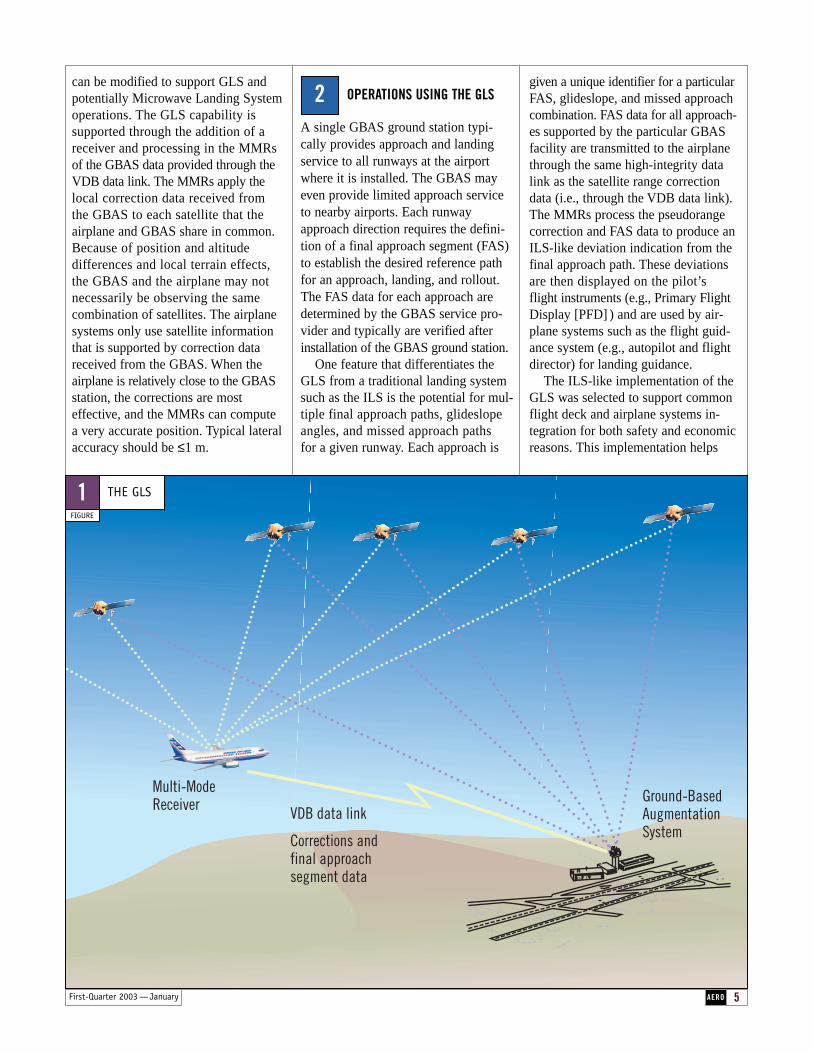
The GLS consists of three major elements — a global satellite constel-lation that supports worldwide navi-gation position fixing, a GBAS facility at each equipped airport that provideslocal navigation satellite correctionsignals, and avionics in each airplanethat process and provide guidance and control based on the satellite andGBAS signals (fig.1).
The GLS uses a navigation satelliteconstellation (e.g., the U.S. GlobalPositioning System [GPS], the planned European Galileo System) for the basic positioning service. TheGPS constellation already is in placeand improvements are planned overthe coming decades. The Galileo con-stellation is scheduled to be availablein 2008.
The basic positioning service isaugmented locally — at or near theairport — through a GBAS radio transmitter facility. Because the groundfacility is located at a known surveyedpoint, the GBAS can estimate theerrors contained in the basic position-ing data. Reference receivers in theGBAS compare the basic positioningdata with the known position of thefacility and compute corrections on a satellite-by-satellite basis. Thecorrections are called pseudorange cor-rections because the primary parameterof interest is the distance between theGBAS facility and individual satellites.The satellite constellation is continu-ously in motion, and satellites ascendand descend over the horizon whenobserved from any point on Earth. The GBAS calculates corrections forall the satellites that meet the specifiedin-view criteria and transmits thatinformation to the nearby airplanesover a VHF Data Broadcast (VDB)data link.
Boeing airplanes that are currentlybeing produced contain Multi-ModeReceivers (MMR) that supportInstrument Landing System (ILS) andbasic GPS operations. These MMRs
1
F or an Air Traffic Service provider.The GBAS service provides theradiated signal in space that can beused by suitably equipped airplanesas the basis of a GNSS landing system (GLS). The initial SARPS support an approach service. Futurerefinements should lead to full low-visibility service (i.e., takeoff,approach, and landing) and low-visibility taxi operations. This article describes
1. Elements of the GLS.
2. Operations using the GLS.
3. Benefits of the GLS.
4. Operational experience.
AERO 5First-Quarter 2003 — January
can be modified to support GLS andpotentially Microwave Landing Systemoperations. The GLS capability is supported through the addition of areceiver and processing in the MMRsof the GBAS data provided through theVDB data link. The MMRs apply thelocal correction data received from the GBAS to each satellite that theairplane and GBAS share in common.Because of position and altitude differences and local terrain effects,the GBAS and the airplane may notnecessarily be observing the samecombination of satellites. The airplanesystems only use satellite informationthat is supported by correction datareceived from the GBAS. When the airplane is relatively close to the GBASstation, the corrections are most effective, and the MMRs can computea very accurate position. Typical lateralaccuracy should be ≤1 m.
OPERATIONS USING THE GLS
A single GBAS ground station typi-cally provides approach and landingservice to all runways at the airportwhere it is installed. The GBAS mayeven provide limited approach serviceto nearby airports. Each runwayapproach direction requires the defini-tion of a final approach segment (FAS)to establish the desired reference pathfor an approach, landing, and rollout.The FAS data for each approach aredetermined by the GBAS service pro-vider and typically are verified afterinstallation of the GBAS ground station.
One feature that differentiates theGLS from a traditional landing systemsuch as the ILS is the potential for mul-tiple final approach paths, glideslopeangles, and missed approach paths for a given runway. Each approach is
2given a unique identifier for a particularFAS, glideslope, and missed approachcombination. FAS data for all approach-es supported by the particular GBASfacility are transmitted to the airplanethrough the same high-integrity datalink as the satellite range correctiondata (i.e., through the VDB data link).The MMRs process the pseudorangecorrection and FAS data to produce anILS-like deviation indication from thefinal approach path. These deviationsare then displayed on the pilot’s flight instruments (e.g., Primary FlightDisplay [PFD] ) and are used by air-plane systems such as the flight guid-ance system (e.g., autopilot and flightdirector) for landing guidance.
The ILS-like implementation of theGLS was selected to support commonflight deck and airplane systems in-tegration for both safety and economicreasons. This implementation helps
Multi-Mode Receiver VDB data link
Corrections and final approach segment data
Ground-BasedAugmentation System
THE GLS
FIGURE
1
6 AERO First-Quarter 2003 — January
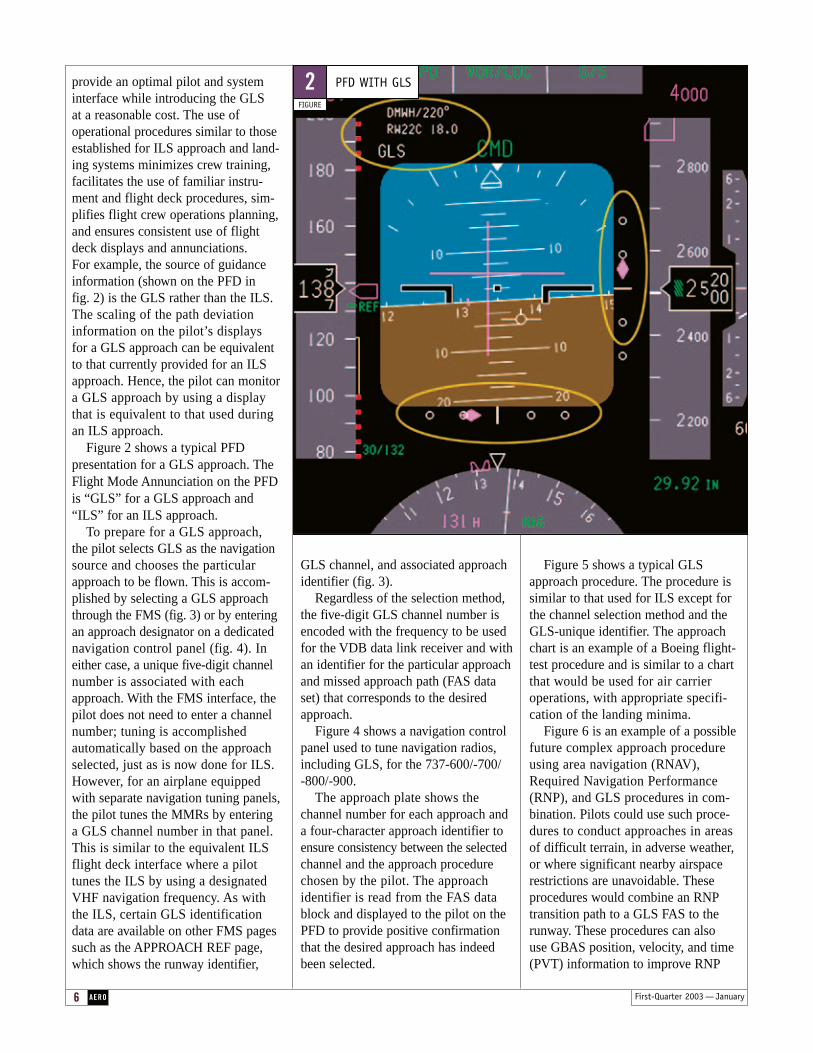
provide an optimal pilot and systeminterface while introducing the GLS at a reasonable cost. The use of operational procedures similar to thoseestablished for ILS approach and land-ing systems minimizes crew training,facilitates the use of familiar instru-ment and flight deck procedures, sim-plifies flight crew operations planning,and ensures consistent use of flightdeck displays and annunciations. For example, the source of guidance information (shown on the PFD in fig. 2) is the GLS rather than the ILS.The scaling of the path deviation information on the pilot’s displays for a GLS approach can be equivalentto that currently provided for an ILSapproach. Hence, the pilot can monitora GLS approach by using a display that is equivalent to that used duringan ILS approach.
Figure 2 shows a typical PFD presentation for a GLS approach. TheFlight Mode Annunciation on the PFDis “GLS” for a GLS approach and“ILS” for an ILS approach.
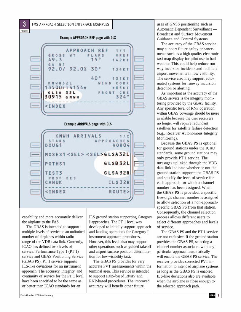
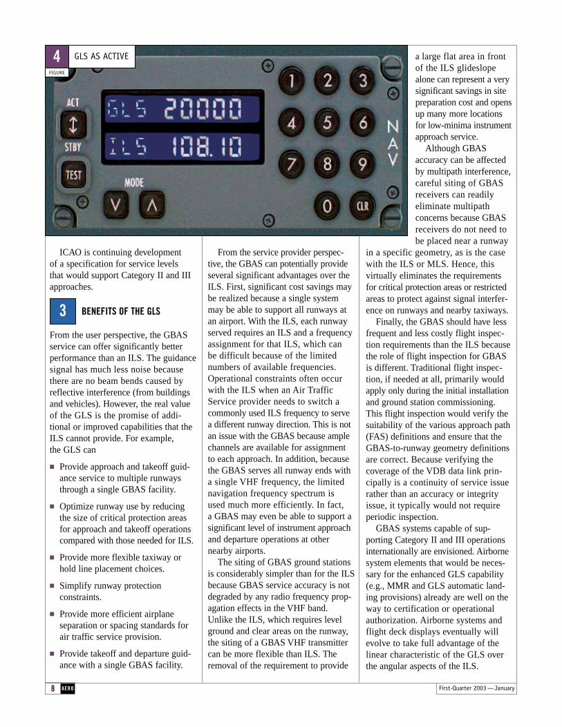
To prepare for a GLS approach,the pilot selects GLS as the navigationsource and chooses the particularapproach to be flown. This is accom-plished by selecting a GLS approachthrough the FMS (fig. 3) or by enteringan approach designator on a dedicatednavigation control panel (fig. 4). Ineither case, a unique five-digit channelnumber is associated with eachapproach. With the FMS interface, thepilot does not need to enter a channelnumber; tuning is accomplished automatically based on the approachselected, just as is now done for ILS.However, for an airplane equippedwith separate navigation tuning panels,the pilot tunes the MMRs by entering a GLS channel number in that panel.This is similar to the equivalent ILSflight deck interface where a pilot tunes the ILS by using a designatedVHF navigation frequency. As with the ILS, certain GLS identification data are available on other FMS pagessuch as the APPROACH REF page,which shows the runway identifier,
GLS channel, and associated approachidentifier (fig. 3).
Regardless of the selection method,the five-digit GLS channel number isencoded with the frequency to be usedfor the VDB data link receiver and withan identifier for the particular approachand missed approach path (FAS dataset) that corresponds to the desiredapproach.
Figure 4 shows a navigation controlpanel used to tune navigation radios,including GLS, for the 737-600/-700/-800/-900.
The approach plate shows thechannel number for each approach anda four-character approach identifier toensure consistency between the selectedchannel and the approach procedurechosen by the pilot. The approach identifier is read from the FAS datablock and displayed to the pilot on thePFD to provide positive confirmationthat the desired approach has indeedbeen selected.
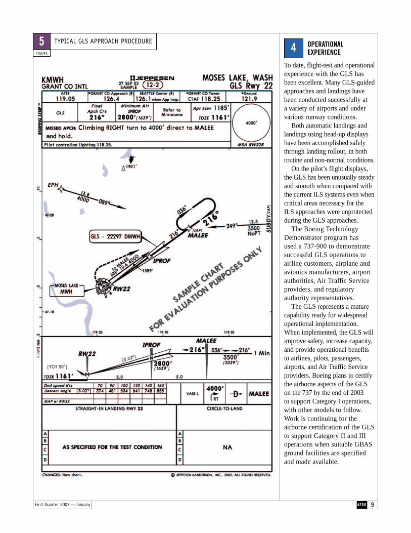
Figure 5 shows a typical GLSapproach procedure. The procedure issimilar to that used for ILS except forthe channel selection method and theGLS-unique identifier. The approachchart is an example of a Boeing flight-test procedure and is similar to a chartthat would be used for air carrieroperations, with appropriate specifi-cation of the landing minima.
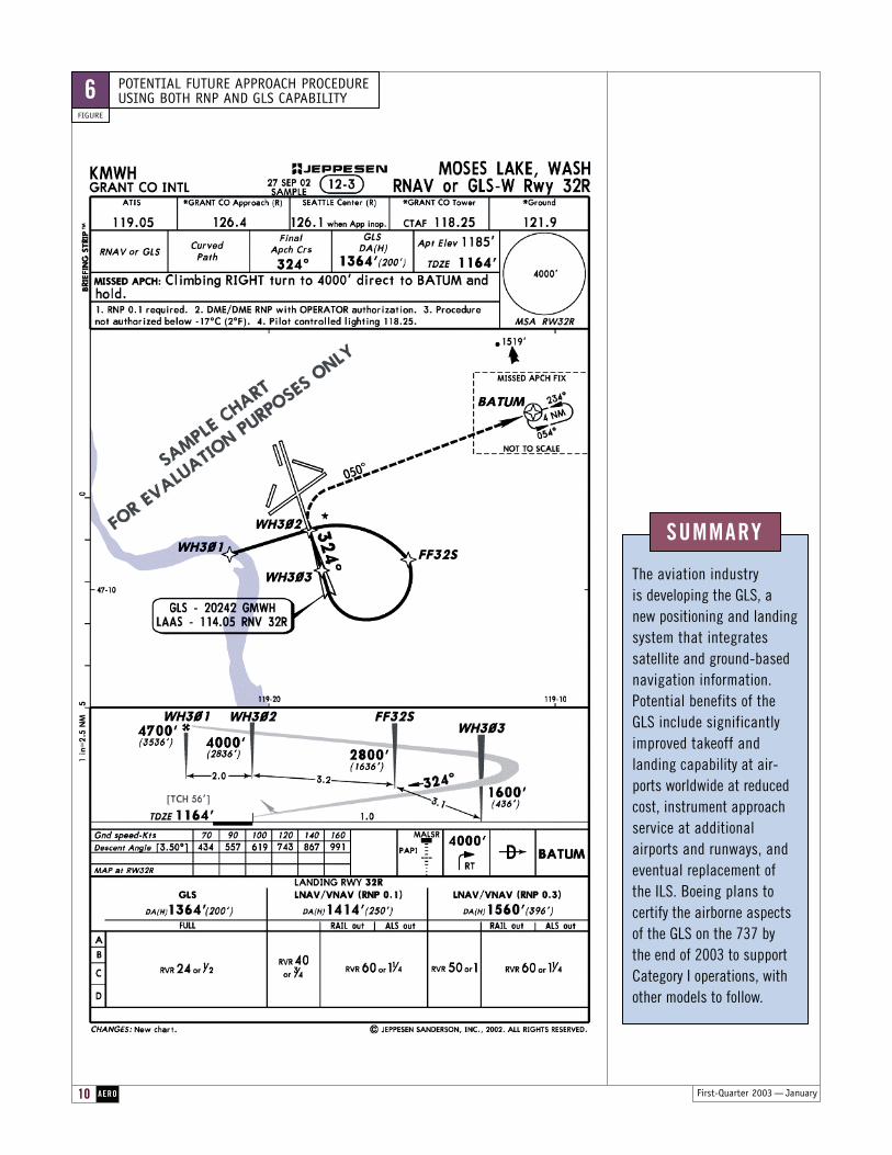
Figure 6 is an example of a possiblefuture complex approach procedureusing area navigation (RNAV),Required Navigation Performance(RNP), and GLS procedures in com-bination. Pilots could use such proce-dures to conduct approaches in areasof difficult terrain, in adverse weather,or where significant nearby airspacerestrictions are unavoidable. These procedures would combine an RNPtransition path to a GLS FAS to therunway. These procedures can also use GBAS position, velocity, and time(PVT) information to improve RNP
PFD WITH GLS
FIGURE
2
7AEROFirst-Quarter 2003 — January
capability and more accurately deliverthe airplane to the FAS.
The GBAS is intended to supportmultiple levels of service to an unlimitednumber of airplanes within radio range of the VDB data link. Currently,ICAO has defined two levels of service: Performance Type 1 (PT 1)service and GBAS Positioning Service(GBAS PS). PT 1 service supports ILS-like deviations for an instrumentapproach. The accuracy, integrity, andcontinuity of service for the PT 1 levelhave been specified to be the same asor better than ICAO standards for an
ILS ground station supporting CategoryI approaches. The PT 1 level wasdeveloped to initially support approachand landing operations for Category Iinstrument approach procedures.However, this level also may supportother operations such as guided takeoffand airport surface position determina-tion for low-visibility taxi.
The GBAS PS provides for veryaccurate PVT measurements within theterminal area. This service is intendedto support FMS-based RNAV andRNP-based procedures. The improvedaccuracy will benefit other future
FMS APPROACH SELECTION INTERFACE EXAMPLES
FIGURE
3
Example APPROACH REF page with GLS
Example ARRIVALS page with GLS
uses of GNSS positioning such asAutomatic Dependent Surveillance —Broadcast and Surface MovementGuidance and Control Systems.
The accuracy of the GBAS servicemay support future safety enhance-ments such as a high-quality electronictaxi map display for pilot use in badweather. This could help reduce run-way incursion incidents and facilitateairport movements in low visibility.The service also may support auto-mated systems for runway incursiondetection or alerting.
As important as the accuracy of theGBAS service is the integrity moni-toring provided by the GBAS facility.Any specific level of RNP operationwithin GBAS coverage should be moreavailable because the user receivers no longer will require redundant satellites for satellite failure detection(e.g., Receiver Autonomous IntegrityMonitoring).
Because the GBAS PS is optionalfor ground stations under the ICAOstandards, some ground stations mayonly provide PT 1 service. The messages uplinked through the VDBdata link indicate whether or not theground station supports the GBAS PSand specify the level of service foreach approach for which a channelnumber has been assigned. When the GBAS PS is provided, a specific five-digit channel number is assignedto allow selection of a non-approach-specific GBAS PS from that station. Consequently, the channel selectionprocess allows different users toselect different approaches and levelsof service.
The GBAS PS and the PT 1 serviceare not exclusive. If the ground stationprovides the GBAS PS, selecting achannel number associated with anyparticular approach automatically will enable the GBAS PS service. Thereceiver provides corrected PVT in-formation to intended airplane systemsas long as the GBAS PS is enabled.ILS-like deviations also are availablewhen the airplane is close enough tothe selected approach path.
8 AERO First-Quarter 2003 — January
ICAO is continuing development of a specification for service levels that would support Category II and IIIapproaches.
BENEFITS OF THE GLS
From the user perspective, the GBASservice can offer significantly betterperformance than an ILS. The guidancesignal has much less noise becausethere are no beam bends caused byreflective interference (from buildingsand vehicles). However, the real valueof the GLS is the promise of addi-tional or improved capabilities that the ILS cannot provide. For example,the GLS can
■ Provide approach and takeoff guid-ance service to multiple runwaysthrough a single GBAS facility.
■ Optimize runway use by reducingthe size of critical protection areasfor approach and takeoff operationscompared with those needed for ILS.
■ Provide more flexible taxiway orhold line placement choices.
■ Simplify runway protection constraints.
■ Provide more efficient airplane separation or spacing standards forair traffic service provision.
■ Provide takeoff and departure guid-ance with a single GBAS facility.
From the service provider perspec-tive, the GBAS can potentially provideseveral significant advantages over theILS. First, significant cost savings maybe realized because a single systemmay be able to support all runways atan airport. With the ILS, each runwayserved requires an ILS and a frequencyassignment for that ILS, which can be difficult because of the limited numbers of available frequencies.Operational constraints often occurwith the ILS when an Air TrafficService provider needs to switch acommonly used ILS frequency to servea different runway direction. This is notan issue with the GBAS because amplechannels are available for assignmentto each approach. In addition, becausethe GBAS serves all runway ends witha single VHF frequency, the limitednavigation frequency spectrum is used much more efficiently. In fact,a GBAS may even be able to support asignificant level of instrument approachand departure operations at other nearby airports.
The siting of GBAS ground stationsis considerably simpler than for the ILSbecause GBAS service accuracy is notdegraded by any radio frequency prop-agation effects in the VHF band.Unlike the ILS, which requires levelground and clear areas on the runway,the siting of a GBAS VHF transmittercan be more flexible than ILS. Theremoval of the requirement to provide
a large flat area in front of the ILS glideslopealone can represent a very significant savings in sitepreparation cost and opensup many more locationsfor low-minima instrumentapproach service.
Although GBAS accuracy can be affectedby multipath interference,careful siting of GBASreceivers can readilyeliminate multipath concerns because GBASreceivers do not need tobe placed near a runway
in a specific geometry, as is the casewith the ILS or MLS. Hence, this virtually eliminates the requirementsfor critical protection areas or restrictedareas to protect against signal interfer-ence on runways and nearby taxiways.
Finally, the GBAS should have lessfrequent and less costly flight inspec-tion requirements than the ILS becausethe role of flight inspection for GBASis different. Traditional flight inspec-tion, if needed at all, primarily wouldapply only during the initial installationand ground station commissioning.This flight inspection would verify thesuitability of the various approach path(FAS) definitions and ensure that theGBAS-to-runway geometry definitionsare correct. Because verifying the coverage of the VDB data link prin-cipally is a continuity of service issuerather than an accuracy or integrityissue, it typically would not requireperiodic inspection.
GBAS systems capable of sup-porting Category II and III operations internationally are envisioned. Airbornesystem elements that would be neces-sary for the enhanced GLS capability(e.g., MMR and GLS automatic land-ing provisions) already are well on theway to certification or operationalauthorization. Airborne systems andflight deck displays eventually willevolve to take full advantage of the linear characteristic of the GLS overthe angular aspects of the ILS.
GLS AS ACTIVE
FIGURE
4
3
AERO 9First-Quarter 2003 — January
OPERATIONAL EXPERIENCE
To date, flight-test and operationalexperience with the GLS hasbeen excellent. Many GLS-guidedapproaches and landings havebeen conducted successfully at a variety of airports and undervarious runway conditions.
Both automatic landings and landings using head-up displayshave been accomplished safelythrough landing rollout, in bothroutine and non-normal conditions.
On the pilot’s flight displays,the GLS has been unusually steadyand smooth when compared withthe current ILS systems even whencritical areas necessary for theILS approaches were unprotectedduring the GLS approaches.
The Boeing TechnologyDemonstrator program has used a 737-900 to demonstrate successful GLS operations toairline customers, airplane andavionics manufacturers, airportauthorities, Air Traffic Serviceproviders, and regulatoryauthority representatives.
The GLS represents a maturecapability ready for widespreadoperational implementation.When implemented, the GLS willimprove safety, increase capacity,and provide operational benefitsto airlines, pilots, passengers,airports, and Air Traffic Serviceproviders. Boeing plans to certifythe airborne aspects of the GLSon the 737 by the end of 2003 to support Category I operations,with other models to follow. Work is continuing for the airborne certification of the GLSto support Category II and IIIoperations when suitable GBASground facilities are specifiedand made available.
4TYPICAL GLS APPROACH PROCEDURE
FIGURE
5
SUMMARY
The aviation industryis developing the GLS, a new positioning and landingsystem that integratessatellite and ground-basednavigation information.Potential benefits of the GLS include significantlyimproved takeoff andlanding capability at air-ports worldwide at reducedcost, instrument approachservice at additional airports and runways, andeventual replacement of the ILS. Boeing plans to certify the airborne aspects of the GLS on the 737 by the end of 2003 to supportCategory I operations, withother models to follow.
First-Quarter 2003 — January
POTENTIAL FUTURE APPROACH PROCEDURE USING BOTH RNP AND GLS CAPABILITY
FIGURE
6
10 AERO
11AERO
About the Authors
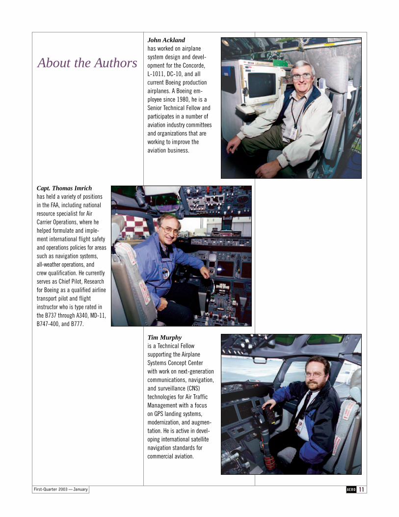
Capt. Thomas Imrichhas held a variety of positionsin the FAA, including nationalresource specialist for AirCarrier Operations, where hehelped formulate and imple-ment international flight safetyand operations policies for areassuch as navigation systems, all-weather operations, and crew qualification. He currentlyserves as Chief Pilot, Researchfor Boeing as a qualified airlinetransport pilot and flightinstructor who is type rated inthe B737 through A340, MD-11,B747-400, and B777.
John Acklandhas worked on airplane system design and devel-opment for the Concorde, L-1011, DC-10, and all current Boeing productionairplanes. A Boeing em-ployee since 1980, he is aSenior Technical Fellow andparticipates in a number ofaviation industry committeesand organizations that areworking to improve the aviation business.
Tim Murphyis a Technical Fellow supporting the AirplaneSystems Concept Center with work on next-generationcommunications, navigation,and surveillance (CNS) technologies for Air TrafficManagement with a focus on GPS landing systems, modernization, and augmen-tation. He is active in devel-oping international satellitenavigation standards for commercial aviation.
First-Quarter 2003 — January
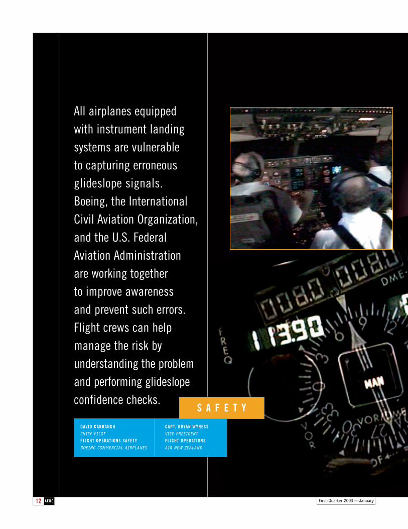
All airplanes equipped with instrument landingsystems are vulnerable to capturing erroneousglideslope signals. Boeing, the InternationalCivil Aviation Organization,and the U.S. FederalAviation Administration are working together to improve awareness and prevent such errors.Flight crews can help manage the risk by understanding the problemand performing glideslopeconfidence checks.
AERO First-Quarter 2003 — January12
S A F E T Y
DAVID CARBAUGHCHIEF PILOT
FLIGHT OPERATIONS SAFETYBOEING COMMERCIAL AIRPLANES
CAPT. BRYAN WYNESSVICE PRESIDENT
FLIGHT OPERATIONSAIR NEW ZEALAND

First-Quarter 2003 — January 13AERO
First-Quarter 2003 — January14 AERO
INCIDENT INVOLVING AN ERRONEOUS GLIDESLOPE SIGNAL
On the night of July 29, 2000, anAir New Zealand 767 was on a routineflight from Auckland, New Zealand,to Apia, Western Samoa. The night wasmoonless, with scattered clouds that prevented visibility of the runway lights.
The flight crew members were expe-rienced in conducting routine automaticlanding approaches in low visibility.They considered a routine automaticlanding approach to be safe if the autopilot was coupled to the airplane,no warning indications were visible,and a valid Morse code identifier signal came from the ground navigation aids.
Well prepared before descent, theflight crew thoroughly briefed for the approach. When the crew selected
1ith the advent of instru-ment landing systems(ILS) in the 1940s came
the possibility of erroneous or falseglideslope indications under certaincircumstances. One such erro-neous indication recently occurredon several 767, 777, and Airbusairplanes, resulting in coupled ILSapproaches being flown toward apoint short of the runway. Thiskind of problem can occur on anyairplane with any ILS receiver.
Boeing has taken action to helpprevent such incidents by revisingoperations manuals and workingwith the International Civil Aviation Organization (ICAO)
and the U.S. Federal AviationAdministration (FAA) to addressmaintenance errors that can causeerroneous glideslope signals. Thesubtle nature of the indicationsmakes it imperative that flight crewsalso help manage the risk by under-standing the problem and performingglideslope confidence checks.
This article describes
1. Incident involving an erroneous glideslope signal.
2. Causes of erroneous glideslope signals.
3. Flight crew actions.
4. Industry actions.
W
Amplifier 1
Primarytransmitter
Backuptransmitter Monitor
Control tower
Amplifier 2
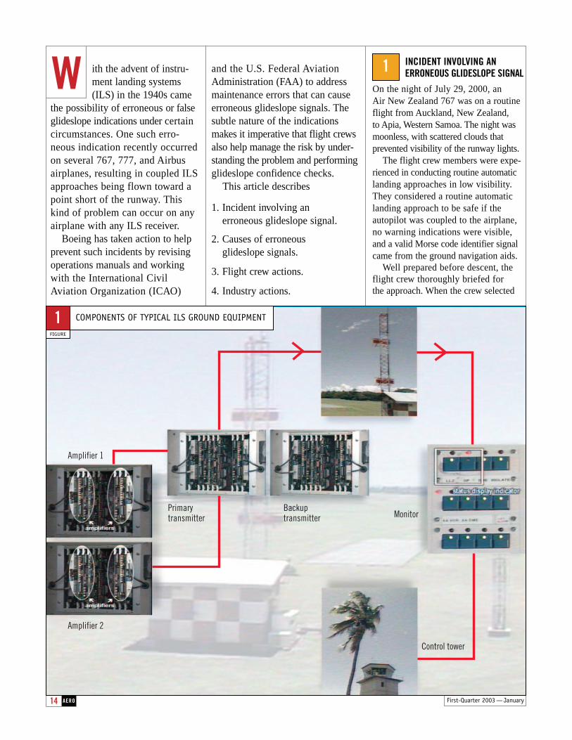
COMPONENTS OF TYPICAL ILS GROUND EQUIPMENT
FIGURE
1
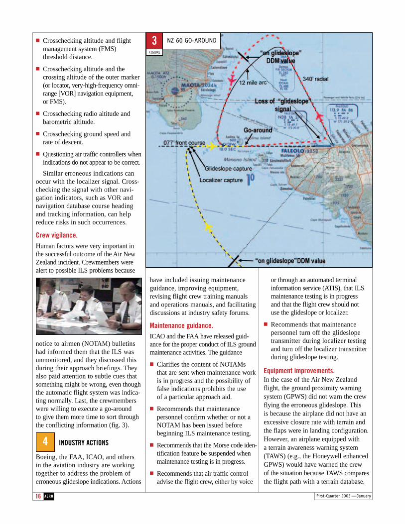
the approach mode, the glideslope cap-ture occurred almost immediately. AllILS indications appeared to be correct.With all three autopilots engaged, thecaptain concentrated on configuring the airplane and slowing it for landing.The crew attributed the slightly steepdescent of the airplane to its heavyweight and tailwinds. The crew noted a good Morse code identifier signaland no warning indications. At 1,000 ft,the crew completed the landing checks.Shortly thereafter, the first officerobserved the close proximity of
the islandlights out hisside window.The captainnoticed thatthe distancemeasuringequipment(DME) indications
differed slightly from what he wouldhave expected.
The captain executed a timely go-around 5.5 mi from the runwayat an altitude of less than 400 ft. The crew successfully executed a secondapproach by using the localizer andignoring the on-glideslope indications.
CAUSES OF ERRONEOUSGLIDESLOPE SIGNALS
Investigation of the Air New Zealandincident revealed important informa-tion about the causes of erroneousglideslope signals. Understanding
First-Quarter 2003 — January 15AERO
these causes requires a discussion ofthe ILS and its normal operation.
ILS ground equipment provides horizontal and vertical guidance in-formation to airplane instrumentation. The equipment typically comprises five components: a localizer transmis-sion system, a glideslope transmission system, a DME or marker system,a standby transmitter, and a remotecontrol and indicator system (fig. 1).
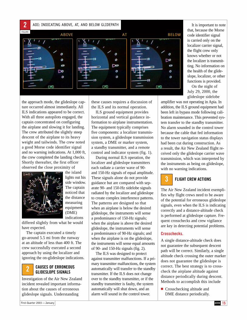
During normal ILS operation, thelocalizer and glideslope transmitterseach radiate a carrier wave of 90- and 150-Hz signals of equal amplitude.These signals alone do not provide guidance but are compared with sep-arate 90- and 150-Hz sidelobe signals radiated by the localizer and glideslopeto create complex interference patterns.The patterns are designed so that when an airplane is below the desiredglideslope, the instruments will sense a predominance of 150-Hz signals;when the airplane is above the desiredglideslope, the instruments will sense a predominance of 90-Hz signals; andwhen the airplane is on the glideslope,the instruments will sense equal amountsof 90- and 150-Hz signals (fig. 2).
The ILS was designed to protectagainst transmitter malfunctions. If a pri-mary transmitter malfunctions, the systemautomatically will transfer to the standbytransmitter. If the ILS does not changeover to the standby transmitter, or if thestandby transmitter is faulty, the systemautomatically will shut down, and analarm will sound in the control tower.
It is important to notethat, because the Morsecode identifier signal is carried only on thelocalizer carrier signal,the flight crew onlyknows whether or notthe localizer is transmit-ting. No information onthe health of the glide-slope, localizer, or otherfunctions is provided.
On the night of July 29, 2000, theglideslope sidelobe
amplifier was not operating in Apia. Inaddition, the ILS ground equipment hadbeen left in bypass mode following cali-bration maintenance. This prevented sys-tem transfer to the standby transmitter.No alarm sounded in the control towerbecause the cable that fed informationto the tower navigation status displayshad been cut during construction. As a result, the Air New Zealand flight re-ceived only the glideslope carrier wavetransmission, which was interpreted bythe instruments as being on glideslope,with no warning indications.
FLIGHT CREW ACTIONS
The Air New Zealand incident exempli-fies why flight crews need to be awareof the potential for erroneous glideslopesignals, even when the ILS is indicatingcorrectly and a distance-altitude checkis performed at glideslope capture. Fre-quent crosschecks and crew vigilanceare key in detecting potential problems.
Crosschecks.A single distance-altitude check doesnot guarantee the subsequent descentpath will be correct. Similarly, a singlealtitude check crossing the outer markerdoes not guarantee the glideslope is correct. The best strategy is to cross-check the airplane altitude against distance periodically during descent.Methods to accomplish this include
■ Crosschecking altitude and DME distance periodically.
ADI: INDICATING ABOVE, AT, AND BELOW GLIDEPATH
FIGURE
2
2
3
16 AERO
■ Crosschecking altitude and flightmanagement system (FMS) threshold distance.
■ Crosschecking altitude and the crossing altitude of the outer marker(or locator, very-high-frequency omni-range [VOR] navigation equipment,or FMS).
■ Crosschecking radio altitude andbarometric altitude.
■ Crosschecking ground speed and rate of descent.
■ Questioning air traffic controllers whenindications do not appear to be correct.
Similar erroneous indications canoccur with the localizer signal. Cross-checking the signal with other navi-gation indicators, such as VOR and navigation database course headingand tracking information, can helpreduce risks in such occurrences.
Crew vigilance.Human factors were very important inthe successful outcome of the Air NewZealand incident. Crewmembers werealert to possible ILS problems because
notice to airmen (NOTAM) bulletins had informed them that the ILS was unmonitored, and they discussed thisduring their approach briefings. Theyalso paid attention to subtle cues thatsomething might be wrong, even thoughthe automatic flight system was indica-ting normally. Last, the crewmemberswere willing to execute a go-around to give them more time to sort throughthe conflicting information (fig. 3).
INDUSTRY ACTIONS
Boeing, the FAA, ICAO, and others in the aviation industry are workingtogether to address the problem oferroneous glideslope indications. Actions
have included issuing maintenance guidance, improving equipment,revising flight crew training manualsand operations manuals, and facilitating discussions at industry safety forums.
Maintenance guidance.ICAO and the FAA have released guid-ance for the proper conduct of ILS groundmaintenance activities. The guidance
■ Clarifies the content of NOTAMs that are sent when maintenance workis in progress and the possibility offalse indications prohibits the use of a particular approach aid.
■ Recommends that maintenance personnel confirm whether or not aNOTAM has been issued beforebeginning ILS maintenance testing.
■ Recommends that the Morse code iden-tification feature be suspended whenmaintenance testing is in progress.
■ Recommends that air traffic control advise the flight crew, either by voice
or through an automated terminalinformation service (ATIS), that ILSmaintenance testing is in progress and that the flight crew should not use the glideslope or localizer.
■ Recommends that maintenance personnel turn off the glideslopetransmitter during localizer testingand turn off the localizer transmitterduring glideslope testing.
Equipment improvements.In the case of the Air New Zealandflight, the ground proximity warningsystem (GPWS) did not warn the crewflying the erroneous glideslope. This is because the airplane did not have anexcessive closure rate with terrain andthe flaps were in landing configuration.However, an airplane equipped with a terrain awareness warning system(TAWS) (e.g., the Honeywell enhancedGPWS) would have warned the crew of the situation because TAWS comparesthe flight path with a terrain database.
4
First-Quarter 2003 — January
NZ 60 GO-AROUND
FIGURE
3
17First-Quarter 2003 — January AERO
The transmission of erroneous ILS information at Apia on July 29, 2000, was caused by an unusual set of circum-stances. However, technicians will con-tinue to conduct testing and maintenance of airfield navigation aids. A similar situation could occur in any ILS-equippedairplane during what appears to be a routine instrument approach.
The best defenses against erroneousglideslope indications are understandinghow the ILS works, equipping airplaneswith modern warning systems, and im-plementing training and procedures thatensure crewmembers are prepared to takeappropriate action. Flight crew actionshould include crosschecking the airplanealtitude against distance periodically during descent.
Special recognition is given to in-vestigators David Stobie, Rod Smith,Chris Kriechbaum, Bob Henderson, JoeyAnca, and Dr. Gordon Vette for their con-tributions to understanding this incident.
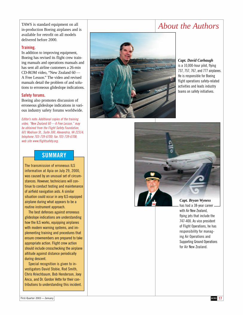
Capt. David Carbaughis a 10,000-hour pilot, flying 737, 757, 767, and 777 airplanes.He is responsible for Boeing flight operations safety-relatedactivities and leads industryteams on safety initiatives.
About the Authors
Capt. Bryan Wynesshas had a 38-year career with Air New Zealand, flying jets that include the 747-400. As vice president of Flight Operations, he hasresponsibility for manag-ing Air Operations andSupporting Ground Operationsfor Air New Zealand.
TAWS is standard equipment on all in-production Boeing airplanes and isavailable for retrofit on all models delivered before 2000.
Training.In addition to improving equipment,Boeing has revised its flight crew train-ing manuals and operations manuals and has sent all airline customers a 26-min CD-ROM video, “New Zealand 60 —A Free Lesson.” The video and revised manuals detail the problem of and solu-tions to erroneous glideslope indications.
Safety forums.Boeing also promotes discussion of erroneous glideslope indications in vari-ous industry safety forums worldwide.
Editor’s note: Additional copies of the training video, “New Zealand 60 — A Free Lesson,” may be obtained from the Flight Safety Foundation, 601 Madison St., Suite 300, Alexandria, VA 22314; telephone 703-739-6700; fax 703-739-6708; web site www.flightsafety.org.
SUMMARY

18 AERO First-Quarter 2003 — January
747ERANDINTRODUCING THE747747ER 747

19AERO
The Longer Range 747-400 airplanes — the 747-400 Extended Range and 747-400 Extended Range Freighter — are the newest members of the 747 family. Through structural and system enhancements, these airplanes offer significant improvements in range and payload and provide greater reliability, maintainability, and flexibility.
T E C H N O L O G Y / P R O D U C T D E V E L O P M E N T
KURT KRAFT
PROGRAM MANAGER
LONGER RANGE 747 PROGRAM
BOEING COMMERCIAL AIRPLANES
ER FREIGHTERER FREIGHTER
First-Quarter 2003 — January
20 AERO First-Quarter 2003 — January
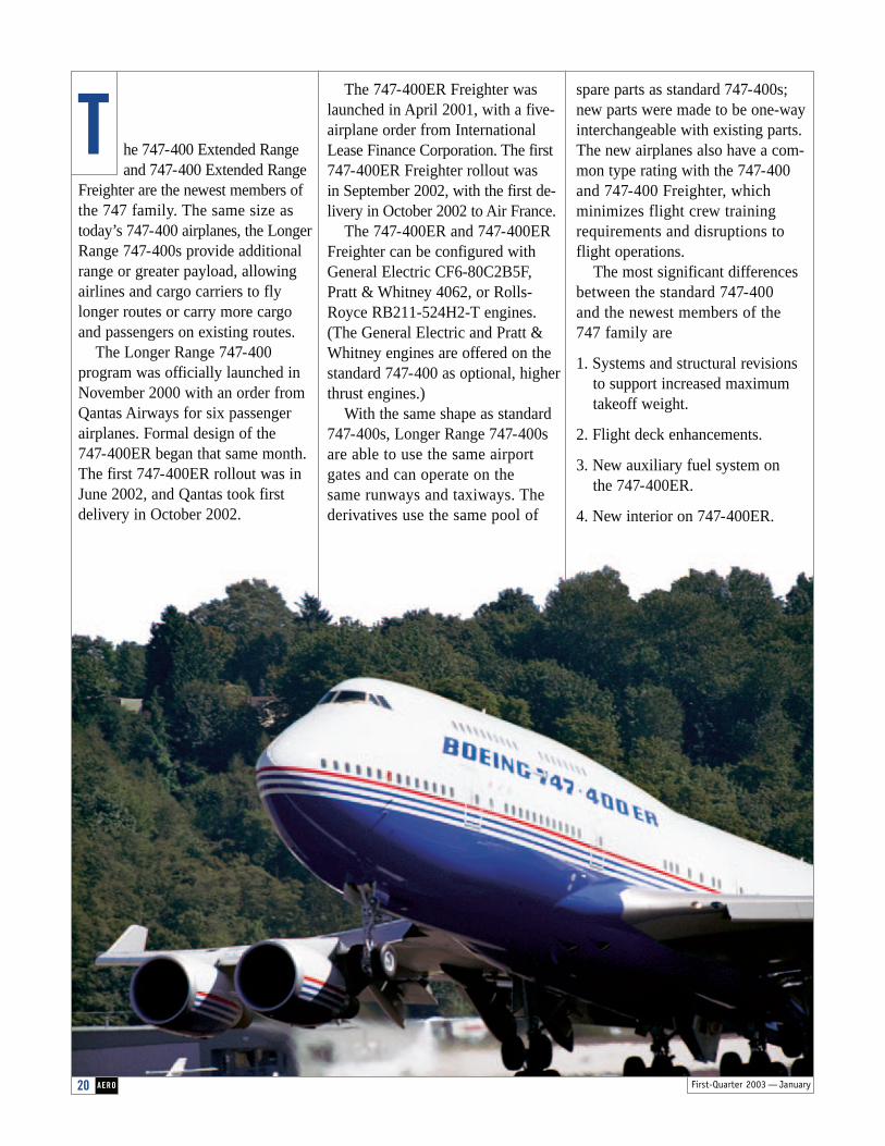
he 747-400 Extended Rangeand 747-400 Extended Range
Freighter are the newest members ofthe 747 family. The same size astoday’s 747-400 airplanes, the LongerRange 747-400s provide additionalrange or greater payload, allowingairlines and cargo carriers to flylonger routes or carry more cargo and passengers on existing routes.
The Longer Range 747-400 program was officially launched inNovember 2000 with an order fromQantas Airways for six passengerairplanes. Formal design of the 747-400ER began that same month.The first 747-400ER rollout was inJune 2002, and Qantas took firstdelivery in October 2002.
The 747-400ER Freighter waslaunched in April 2001, with a five-airplane order from InternationalLease Finance Corporation. The first747-400ER Freighter rollout was in September 2002, with the first de-livery in October 2002 to Air France.
The 747-400ER and 747-400ERFreighter can be configured withGeneral Electric CF6-80C2B5F,Pratt & Whitney 4062, or Rolls-Royce RB211-524H2-T engines.(The General Electric and Pratt &Whitney engines are offered on thestandard 747-400 as optional, higherthrust engines.)
With the same shape as standard747-400s, Longer Range 747-400sare able to use the same airportgates and can operate on the same runways and taxiways. Thederivatives use the same pool of
spare parts as standard 747-400s;new parts were made to be one-wayinterchangeable with existing parts.The new airplanes also have a com-mon type rating with the 747-400and 747-400 Freighter, which minimizes flight crew trainingrequirements and disruptions toflight operations.
The most significant differencesbetween the standard 747-400 and the newest members of the 747 family are
1. Systems and structural revisionsto support increased maximumtakeoff weight.
2. Flight deck enhancements.
3. New auxiliary fuel system on the 747-400ER.
4. New interior on 747-400ER.
T
21AEROFirst-Quarter 2003 — January
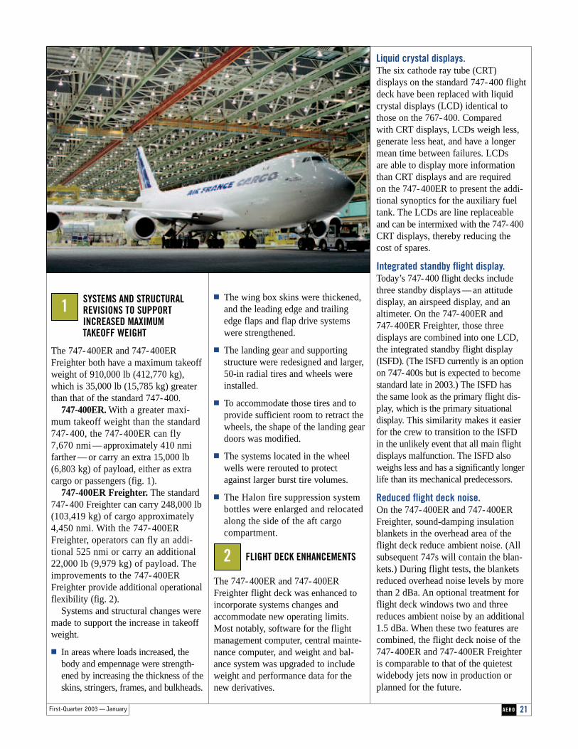
■ The wing box skins were thickened,and the leading edge and trailingedge flaps and flap drive systemswere strengthened.
■ The landing gear and supportingstructure were redesigned and larger,50-in radial tires and wheels wereinstalled.
■ To accommodate those tires and toprovide sufficient room to retract thewheels, the shape of the landing geardoors was modified.
■ The systems located in the wheelwells were rerouted to protect against larger burst tire volumes.
■ The Halon fire suppression systembottles were enlarged and relocatedalong the side of the aft cargo compartment.
FLIGHT DECK ENHANCEMENTS
The 747-400ER and 747-400ERFreighter flight deck was enhanced toincorporate systems changes andaccommodate new operating limits.Most notably, software for the flightmanagement computer, central mainte-nance computer, and weight and bal-ance system was upgraded to includeweight and performance data for thenew derivatives.
SYSTEMS AND STRUCTURALREVISIONS TO SUPPORTINCREASED MAXIMUM TAKEOFF WEIGHT
The 747- 400ER and 747- 400ERFreighter both have a maximum takeoffweight of 910,000 lb (412,770 kg),which is 35,000 lb (15,785 kg) greaterthan that of the standard 747- 400.
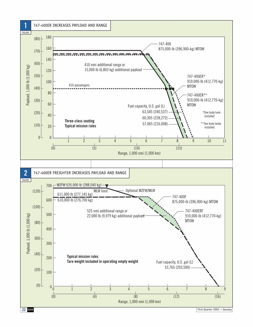
747-400ER. With a greater maxi-mum takeoff weight than the standard747- 400, the 747-400ER can fly 7,670 nmi — approximately 410 nmifarther — or carry an extra 15,000 lb(6,803 kg) of payload, either as extracargo or passengers (fig. 1).
747-400ER Freighter. The standard747- 400 Freighter can carry 248,000 lb(103,419 kg) of cargo approximately4,450 nmi. With the 747- 400ERFreighter, operators can fly an addi-tional 525 nmi or carry an additional22,000 lb (9,979 kg) of payload. Theimprovements to the 747-400ERFreighter provide additional operationalflexibility (fig. 2).
Systems and structural changes weremade to support the increase in takeoffweight.
■ In areas where loads increased, thebody and empennage were strength-ened by increasing the thickness of theskins, stringers, frames, and bulkheads.
Liquid crystal displays. The six cathode ray tube (CRT) displays on the standard 747-400 flightdeck have been replaced with liquidcrystal displays (LCD) identical tothose on the 767-400. Compared with CRT displays, LCDs weigh less,generate less heat, and have a longermean time between failures. LCDs are able to display more informationthan CRT displays and are required on the 747-400ER to present the addi-tional synoptics for the auxiliary fueltank. The LCDs are line replaceable and can be intermixed with the 747-400CRT displays, thereby reducing the cost of spares.
Integrated standby flight display.Today’s 747-400 flight decks includethree standby displays — an attitude display, an airspeed display, and analtimeter. On the 747-400ER and 747-400ER Freighter, those three displays are combined into one LCD,the integrated standby flight display(ISFD). (The ISFD currently is an optionon 747-400s but is expected to becomestandard late in 2003.) The ISFD has the same look as the primary flight dis-play, which is the primary situational display. This similarity makes it easierfor the crew to transition to the ISFD in the unlikely event that all main flight displays malfunction. The ISFD also weighs less and has a significantly longerlife than its mechanical predecessors.
Reduced flight deck noise. On the 747-400ER and 747-400ERFreighter, sound-damping insulationblankets in the overhead area of theflight deck reduce ambient noise. (Allsubsequent 747s will contain the blan-kets.) During flight tests, the blanketsreduced overhead noise levels by morethan 2 dBa. An optional treatment forflight deck windows two and threereduces ambient noise by an additional1.5 dBa. When these two features arecombined, the flight deck noise of the747-400ER and 747-400ER Freighter is comparable to that of the quietestwidebody jets now in production orplanned for the future.
1
2
First-Quarter 2003 — January22 AERO
747-400F875,000-lb (396,900-kg) MTOW
525 nmi additional range or22,000 lb (9,979 kg) additional payload
747-400ERF910,000-lb (412,770-kg) MTOW
700
600
500
400
300
200
100
0
(120)
(100)
(80)
(60)
(40)
(20)
(0)
(0)Range, 1,000 nmi (1,000 km)
53,765 (203,500)Fuel capacity, U.S. gal (L)
611,000 lb (277,145 kg)610,000 lb (276,700 kg)
Paylo
ad, 1
,000
lb (1
,000
kg)
(4) (12) (16)(8)
MZFW 635,000 lb (288,040 kg)MLW limit Optional MZFW/MLW
0 1 2 3 4 5 6 7 8 9
Typical mission rulesTare weight included in operating empty weight
747-400875,000-lb (396,900-kg) MTOW
410 nmi additional range or15,000 lb (6,803 kg) additional payload
747-400ER*910,000-lb (412,770-kg) MTOW
747-400ER**910,000-lb (412,770-kg) MTOW
180
160
140
120
100
80
60
40
20
0
(80)
(70)
(60)
(50)
(40)
(30)
(20)
(10)
021 3 54 6 87 9 10
(0)Range, 1,000 nmi (1,000 km)
63,545 (240,537)
60,305 (228,272)57,065 (216,008)
Fuel capacity, U.S. gal (L)Paylo
ad, 1
,000
lb (1
,000
kg)
(5) (15)(10)
11
416 passengers
*One body tank installed
**Two body tanks installed
Three-class seatingTypical mission rules
747-400ER INCREASES PAYLOAD AND RANGE
FIGURE
1
747-400ER FREIGHTER INCREASES PAYLOAD AND RANGE
FIGURE
2
First-Quarter 2003 — January 23AERO
NEW AUXILIARY FUEL SYSTEMON THE 747-400ER
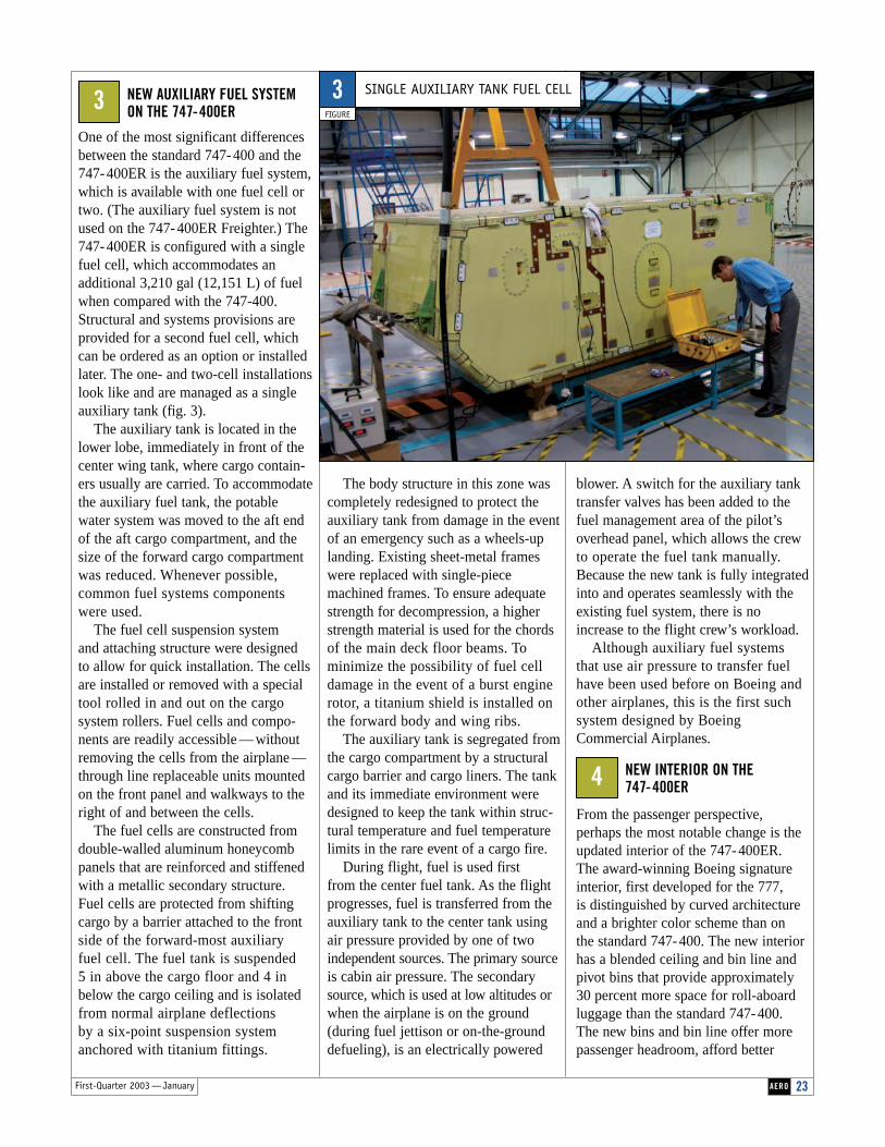
One of the most significant differencesbetween the standard 747- 400 and the747- 400ER is the auxiliary fuel system,which is available with one fuel cell ortwo. (The auxiliary fuel system is notused on the 747- 400ER Freighter.) The747- 400ER is configured with a singlefuel cell, which accommodates an additional 3,210 gal (12,151 L) of fuelwhen compared with the 747-400.Structural and systems provisions areprovided for a second fuel cell, whichcan be ordered as an option or installedlater. The one- and two-cell installationslook like and are managed as a singleauxiliary tank (fig. 3).
The auxiliary tank is located in thelower lobe, immediately in front of thecenter wing tank, where cargo contain-ers usually are carried. To accommodatethe auxiliary fuel tank, the potablewater system was moved to the aft endof the aft cargo compartment, and thesize of the forward cargo compartmentwas reduced. Whenever possible,common fuel systems components were used.
The fuel cell suspension system and attaching structure were designedto allow for quick installation. The cellsare installed or removed with a specialtool rolled in and out on the cargosystem rollers. Fuel cells and compo-nents are readily accessible — withoutremoving the cells from the airplane —through line replaceable units mountedon the front panel and walkways to theright of and between the cells.
The fuel cells are constructed fromdouble-walled aluminum honeycombpanels that are reinforced and stiffenedwith a metallic secondary structure.Fuel cells are protected from shiftingcargo by a barrier attached to the frontside of the forward-most auxiliary fuel cell. The fuel tank is suspended 5 in above the cargo floor and 4 inbelow the cargo ceiling and is isolatedfrom normal airplane deflections by a six-point suspension systemanchored with titanium fittings.
The body structure in this zone wascompletely redesigned to protect theauxiliary tank from damage in the eventof an emergency such as a wheels-uplanding. Existing sheet-metal frameswere replaced with single-piecemachined frames. To ensure adequatestrength for decompression, a higherstrength material is used for the chordsof the main deck floor beams. To minimize the possibility of fuel celldamage in the event of a burst enginerotor, a titanium shield is installed onthe forward body and wing ribs.
The auxiliary tank is segregated fromthe cargo compartment by a structuralcargo barrier and cargo liners. The tankand its immediate environment weredesigned to keep the tank within struc-tural temperature and fuel temperaturelimits in the rare event of a cargo fire.
During flight, fuel is used first from the center fuel tank. As the flightprogresses, fuel is transferred from theauxiliary tank to the center tank usingair pressure provided by one of twoindependent sources. The primary sourceis cabin air pressure. The secondarysource, which is used at low altitudes orwhen the airplane is on the ground(during fuel jettison or on-the-grounddefueling), is an electrically powered
blower. A switch for the auxiliary tanktransfer valves has been added to thefuel management area of the pilot’soverhead panel, which allows the crewto operate the fuel tank manually.Because the new tank is fully integratedinto and operates seamlessly with theexisting fuel system, there is noincrease to the flight crew’s workload.
Although auxiliary fuel systems that use air pressure to transfer fuelhave been used before on Boeing andother airplanes, this is the first such system designed by BoeingCommercial Airplanes.
NEW INTERIOR ON THE 747-400ER
From the passenger perspective,perhaps the most notable change is theupdated interior of the 747-400ER. The award-winning Boeing signatureinterior, first developed for the 777,is distinguished by curved architectureand a brighter color scheme than on the standard 747-400. The new interiorhas a blended ceiling and bin line andpivot bins that provide approximately30 percent more space for roll-aboardluggage than the standard 747-400. The new bins and bin line offer morepassenger headroom, afford better
3 SINGLE AUXILIARY TANK FUEL CELL
FIGURE
3
4

24 AERO First-Quarter 2003 — January
pump. After each flight, the system toggles from one pump to the other.This distributes operating hoursbetween the pumps and provides abackup if one pump fails on the groundor during flight.
A quick-charge emergency lightingbattery replaces the trickle-charge battery. The new battery weighs less, isslightly less expensive, and has a longerlife expectancy, which makes it moreeconomical. More significant, thequick-charge battery can be rechargedin approximately 1 hr, compared with 8 to 10 hr for the trickle-charge battery.This difference allows operators toreturn airplanes to service much morequickly after using, maintaining, or testing emergency lighting.
Light-emitting-diode–illuminatedsign packs replace incandescent bulbinformation sign packs. The new signsare brighter, are similarly priced, andhave a significantly longer life expec-tancy, which translates into less main-tenance and lower maintenance costs.
New backbone wiring for the in-flight entertainment interface, whichwill accommodate any interior layout.Because each airline has a differentinterior layout with different in-flightentertainment (IFE) equipment, thewiring for each IFE installation also
access to luggage, and hold stowed lug-gage in place more securely. The upperdeck of the 747-400ER also has twicethe stowage capacity of standard 747-400s. (Boeing is considering whe-ther to offer this new interior on future747-400s and as part of a retrofit forstandard 747-400s already in service.)
During the design process, each interior system was evaluated for relia-bility and maintenance costs. Systemenhancements include the following.
An electrically activated passengeroxygen system replaces the passengeroxygen system on the 747-400. Thenew system, which uses many com-ponents developed for the 777, is easierto rig and maintain than the system onthe 747-400.
A two-pump potable water systemreplaces the pressurized potable watersystem on the standard 747-400. On the747-400, the system is located in theforward cargo hold. Because this spaceis occupied by the auxiliary fuel tankon the 747-400ER, a new potable watertank was designed and located in thebulk cargo area. This tank is fitted with a two-pump water delivery system,similar to that on the 777. The two-pump system increases dispatch relia-bility; if one pump fails, the systemswitches automatically to the functional
differs significantly, making it cumber-some to modify the interior layout afterdelivery. All 747-400ERs equippedwith an IFE system include the newIFE interface backbone wiring, makingit easier, quicker, and more efficient to change the interior layout. (All sub-sequent 747-400 passenger airplaneswill include the new wiring.)
Kurt Krafthas held engineering and leadership positions on a variety ofBoeing propulsion and airplane programs since 1979, including747 Airplane Level Integration Team (ALIT) leader, 767-400Propulsion Platform team leader, and Propulsion chief engineerfor the 737/757 Programs.
About the Author
SUMMARYThe 747-400 ER and 747-400ER Freighter — the newest derivatives of the 747family—are unique in their classes. Features include a maximum takeoff weight of910,000 lb, which makes it possible to fly farther or carrymore payload, and an enhancedflight deck that offers new LCDs, a new ISFD, and addi-tional insulation to reduce noise.The 747-400ER also has a new auxiliary fuel system,available with one fuel cell ortwo; a newly designed interior;and enhanced interior systems.

First-Quarter 2003 — January
Seating (typical three-class configuration)
Maximum takeoff weight
Maximum landing weight
Range: Statute miles
City pairs
Cruise speed at 35,000 ft
Engines: maximum thrust
Maximum fuel capacity
Length
Wingspan
Tail height
Cargo volume
Exterior diameter
Interior cross-section width
747-400
416
875,000 lb (396,900 kg)
652,000 lb (295,740 kg)
8,360 miles7,260 nmi13,445 km
Los Angeles–Hong KongLos Angeles–Sydney Singapore–London
Mach 0.855567 mi/h (912 km/h)
Pratt & Whitney 406263,300 lb (28,710 kg)
Rolls-Royce RB211-524H2-T59,500 lb (26,990 kg)
General Electric CF6-80C2B5F62,100 lb (28,165 kg)
57,285 U.S. gal (216,840 L)
231 ft 10 in (70.6 m)
211 ft 5 in (64.4 m)
63 ft 8 in (19.4 m)
6,025 ft3 (170.5 m3) or 5,332 ft3 (151 m3)**
21 ft 3.5 in (6.5 m)
20 ft 1.5 in (6.1 m)
747-400ER
416
910,000 lb (412,770 kg)
652,000 lb (295,740 kg)
8,830 miles7,670 nmi14,205 km
New York–Hong KongLos Angeles–MelbourneRio de Janeiro–Perth
Mach 0.855567 mi/h (912 km/h)
Pratt & Whitney 406263,300 lb (28,710 kg)
Rolls-Royce RB211-524H2-T59,500 lb (26,990 kg)
General Electric CF6-80C2B5F62,100 lb (28,165 kg)
63,705 U.S. gal (241,140 L)*
231 ft 10 in (70.6 m)
211 ft 5 in (64.4 m)
63 ft 8 in (19.4 m)
5,599 ft3 (158.6 m3) or 4,837 ft3 (137 m3)***
21 ft 3.5 in (6.5 m)
20 ft 1.5 in (6.1 m)
*With two auxiliary body fuel tanks in the forward lower cargo hold. The fuel capacity with one body tank is 60,495 U.S. gal (228,990 L).
**6,025 ft3 (170.5 m3) = 30 LD-1 containers + bulk; 5,332 ft3 (151 m3) = five pallets, 14 LD-1 containers + bulk (one pallet = 96 in x 125 in, 244 cm x 318 cm).
***5,599 ft3 (158.6 m3) = 28 LD-1 containers + bulk; 4,837 ft3 (137 m3) = four pallets, 14 LD-1 containers + bulk (one pallet = 96 in x 125 in, 244 cm x 318 cm). These volumes are reduced relative to the 747-400 because of the addition of one body fuel tank, basic on the 747-400ER, in the forward lower cargo hold.
25AERO
TECHNICAL CHARACTERISTICS OF THE 747-400 AND 747-400ER

26 AERO First-Quarter 2003 — January
Boeing has developed the Quiet Climb System, an automated avionics feature for quiet procedures that involve thrust cutback after takeoff. By reducingand restoring thrust automatically, the system lessens crew workload andresults in a consistently quiet footprint, which helps airlines comply withrestrictions and may allow for an increase in takeoff payload.
Quiet Climb
27First-Quarter 2003 — January AERO
JERRY FRIEDRICH
AVIONICS DESIGN ENGINEER
NAVIGATION/GUIDANCE/THRUST MANAGEMENT
BOEING COMMERCIAL AIRPLANES
DANIEL MCGREGOR
AIRPORT AND COMMUNITY NOISE ENGINEER
COMMUNITY NOISE
BOEING COMMERCIAL AIRPLANES
DOUGLAS WEIGOLD
AERODYNAMIC PERFORMANCE ENGINEER
AIRPLANE PERFORMANCE & PROPULSION
BOEING COMMERCIAL AIRPLANES
ADVANCED
AVIONICS
FOR
QUIET
OPERATIONS
T E C H N O L O G Y / P R O D U C T D E V E L O P M E N T
System
28 AERO First-Quarter 2003 — January
ith higher density popula-tions surrounding airportsthroughout the world,
the sound of airplanes has become an issue of increasing importance inrecent years. Noise-abatement require-ments and procedures imposed bylocal airport authorities have affectedairline operations in many ways,resulting in restricted hours ofoperation, required weight offloads,fines, and surcharges.
Airplane and engine manufacturershave been successful in producingquieter airplanes, but more stringentnoise-abatement requirements andthe high cost of engine modificationhave prompted the industry to con-sider additional ways to decrease airplane sound in communities.
One alternative is a maneuver inwhich the flight crew takes off withfull takeoff power, climbs rapidly,and then cuts the thrust manually toa predetermined value at a specifiedcutback altitude. The airplane con-tinues to climb, albeit at a muchslower rate, until it is high enoughthat sound in the community is notan issue. The crew then adds morepower to continue flight.
One potential problem with thismaneuver is that the pilot must cutback and restore engine thrust manu-ally at the correct altitudes. The BoeingQuiet Climb System (QCS), which isselected during the takeoff procedure,automatically reduces and restoresengine thrust at the specified altitudes,thereby reducing pilot workload.
In an effort to standardize noise-abatement procedures, the FederalAviation Administration (FAA) has issued advisory guidelines thatdefine departure profiles, includingthe minimum thrust required and
the cutback altitude. This article discusses
1. FAA advisory guidelines.
2. The Boeing QCS.
3. Basics of sound measurements.
4. Effect of the Boeing QCS onsound in communities.
FAA ADVISORY GUIDELINES
In 1993, the FAA issued advisory circular AC91-53A, “Noise AbatementDeparture Profiles,” which standardizesprocedures by defining acceptable criteria for speed and minimums forthrust cutback settings and altitudes forvarious airplane takeoff configurations.
Minimum thrust cutback.The minimum thrust cutback representsthe minimum level of thrust that wouldensure a sufficient climb gradient if anengine were to fail. This thrust value isdetermined by the number of engineson the airplane. On a two-engine airplane, the minimum thrust cutbackensures an engine-inoperative climbgradient of 1.2 percent. If one enginefails after cutback, the thrust from theoperating engine must maintain a climbgradient of at least 1.2 percent. Onthree-engine and four-engine airplanes,the minimum thrust cutbacks areengine-inoperative climb gradients of 1.5 percent and 1.7 percent, respectively.
Zero percent gradient cutback.Under certain conditions, the advisorycircular also allows a thrust cutbackthat maintains a zero percent engine-inoperative climb gradient. This type of cutback is permitted for airplaneswith avionics systems that can detectengine failure and automaticallyincrease the thrust on the remainingengine or engines to a value that maintains the minimum climb gradient.These minimum climb gradients are1.2 percent on a two-engine airplane,1.5 percent on a three-engine airplane,and 1.7 percent on a four-engine airplane.
Cutback altitude.The advisory circular also specifies that the minimum altitude at which thethrust can be reduced, or cut back, is800 ft above ground level (AGL).
THE BOEING QCS
Boeing developed the QCS, anadvanced avionics feature, to directlyassist flight crews in flying the quietdeparture profiles defined in the advisory circular. The QCS controlsthrust reduction and restoration automatically, thereby eliminating the need for manual control and ensuring consistency.
During the takeoff checklist pro-cedure, the pilot selects the QCS andenters the altitudes at which thrustshould be reduced (≥800 ft AGL) andrestored. With the autothrottle systemengaged, the QCS reduces enginethrust when the cutback altitude isreached to maintain the optimal climbangle and airspeed. When the airplanereaches the chosen thrust restorationaltitude (typically 3,000 ft AGL), theQCS restores full climb thrust auto-matically. As such, QCS reduces pilotworkload during a phase of flight thatalready is task intensive.
QCS incorporates multiple safetyfeatures and will continue to operateeven with system failures. If a systemfailure does occur, there are severalmethods for exiting QCS. In the mostcommon method, the pilot selects the takeoff/go-around switches on thethrottle control stand. The pilot can takecontrol of the throttles easily by discon-necting the autothrottle and controllingthe thrust manually, as appropriate.
QCS availability.The QCS is available on all 737-600/-700/-800/-900 airplanes and pro-vides an automatic thrust cutbackengine-inoperative climb gradient of1.2 percent. The zero percent climbgradient QCS is scheduled to becomeavailable in first-quarter 2003 on the 737-600/-700/-800/-900. Boeing also is considering the QCS for the747-400, which would have an
2
1
W
First-Quarter 2003 — January 29AERO
automatic thrust cutback engine-inoperative climb gradient of 1.7 percent.
Other Boeing systems. A system similar to the QCS is avail-able on the MD-90 series. That system,however, requires that the pilot calcu-late the necessary thrust and then enterit manually for automatic thrust cutbackduring takeoff. The 757 also has anoption similar to QCS that provides an engine-inoperative climb gradient of 1.2 percent. To be activated, thecrew must select the system manuallyat the cutback altitude.
BASICS OF SOUND MEASUREMENTS
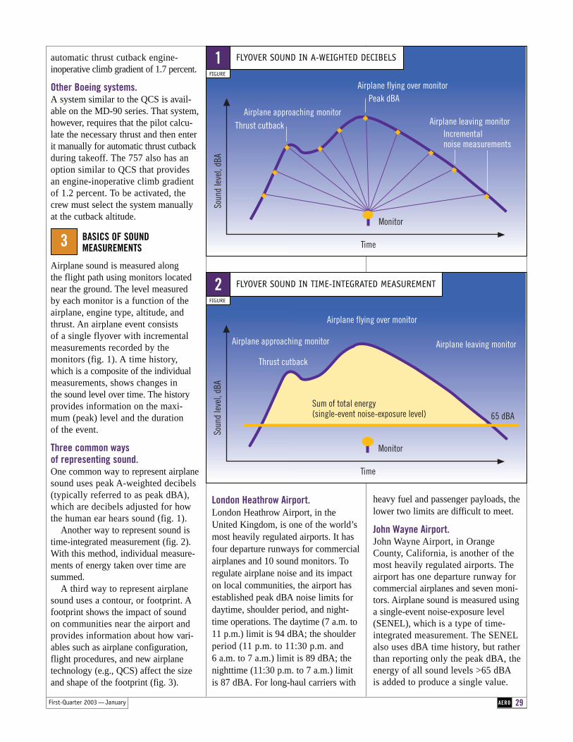
Airplane sound is measured along the flight path using monitors locatednear the ground. The level measured by each monitor is a function of theairplane, engine type, altitude, andthrust. An airplane event consists of a single flyover with incremental measurements recorded by the monitors (fig. 1). A time history,which is a composite of the individualmeasurements, shows changes in the sound level over time. The historyprovides information on the maxi-mum (peak) level and the duration of the event.
Three common ways of representing sound.One common way to represent airplanesound uses peak A-weighted decibels(typically referred to as peak dBA),which are decibels adjusted for how the human ear hears sound (fig. 1).
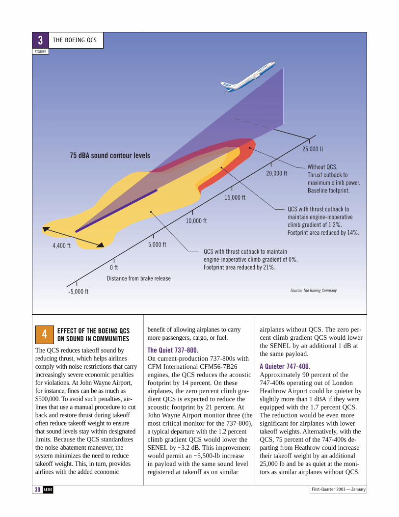
Another way to represent sound istime-integrated measurement (fig. 2).With this method, individual measure-ments of energy taken over time aresummed.
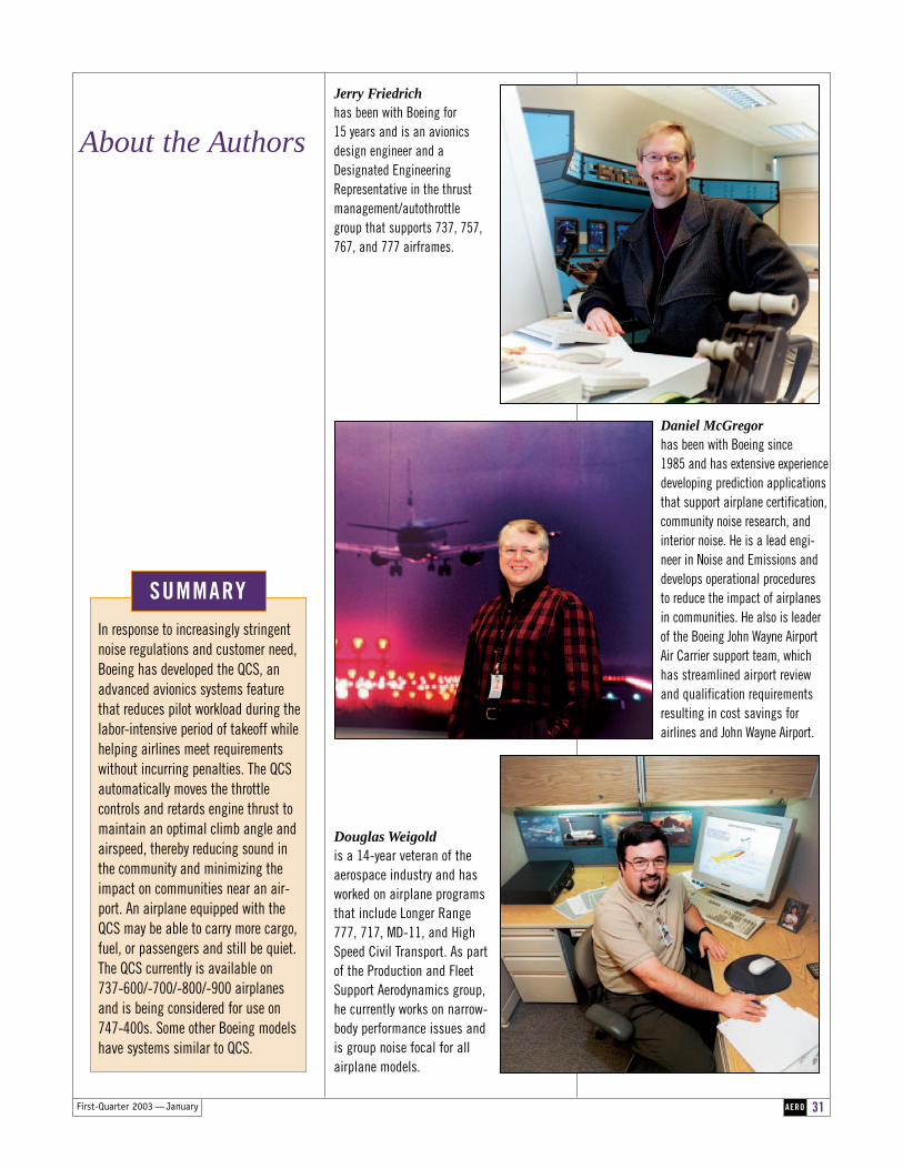
A third way to represent airplanesound uses a contour, or footprint. Afootprint shows the impact of sound on communities near the airport andprovides information about how vari-ables such as airplane configuration,flight procedures, and new airplane technology (e.g., QCS) affect the sizeand shape of the footprint (fig. 3).
London Heathrow Airport.London Heathrow Airport, in theUnited Kingdom, is one of the world’smost heavily regulated airports. It hasfour departure runways for commercialairplanes and 10 sound monitors. Toregulate airplane noise and its impacton local communities, the airport hasestablished peak dBA noise limits fordaytime, shoulder period, and night-time operations. The daytime (7 a.m. to11 p.m.) limit is 94 dBA; the shoulderperiod (11 p.m. to 11:30 p.m. and6 a.m. to 7 a.m.) limit is 89 dBA; thenighttime (11:30 p.m. to 7 a.m.) limit is 87 dBA. For long-haul carriers with
3
heavy fuel and passenger payloads, thelower two limits are difficult to meet.
John Wayne Airport. John Wayne Airport, in Orange County, California, is another of themost heavily regulated airports. The airport has one departure runway forcommercial airplanes and seven moni-tors. Airplane sound is measured usinga single-event noise-exposure level(SENEL), which is a type of time-integrated measurement. The SENELalso uses dBA time history, but ratherthan reporting only the peak dBA, the energy of all sound levels >65 dBA is added to produce a single value.
Time
Soun
d le
vel,
dBA
Thrust cutback
Peak dBA
Monitor
Incremental noise measurements
Airplane approaching monitor
Airplane flying over monitor
Airplane leaving monitor
Time
65 dBA
Soun
d le
vel,
dBA
Thrust cutback
Monitor
Sum of total energy(single-event noise-exposure level)
Airplane approaching monitor
Airplane flying over monitor
Airplane leaving monitor
FLYOVER SOUND IN A-WEIGHTED DECIBELS
FIGURE
1
FLYOVER SOUND IN TIME-INTEGRATED MEASUREMENT
FIGURE
2
First-Quarter 2003 — January
75 dBA sound contour levels
QCS with thrust cutback to maintain engine-inoperative climb gradient of 0%. Footprint area reduced by 21%.
QCS with thrust cutback to maintain engine-inoperative climb gradient of 1.2%. Footprint area reduced by 14%.
Without QCS. Thrust cutback to maximum climb power. Baseline footprint.
Source: The Boeing Company-5,000 ft
4,400 ft 5,000 ft
10,000 ft
15,000 ft
Distance from brake release
20,000 ft
25,000 ft
0 ft
30 AERO
EFFECT OF THE BOEING QCS ON SOUND IN COMMUNITIES
The QCS reduces takeoff sound by reducing thrust, which helps airlinescomply with noise restrictions that carryincreasingly severe economic penaltiesfor violations. At John Wayne Airport,for instance, fines can be as much as$500,000. To avoid such penalties, air-lines that use a manual procedure to cutback and restore thrust during takeoffoften reduce takeoff weight to ensurethat sound levels stay within designatedlimits. Because the QCS standardizesthe noise-abatement maneuver, the system minimizes the need to reducetakeoff weight. This, in turn, providesairlines with the added economic
benefit of allowing airplanes to carrymore passengers, cargo, or fuel.
The Quiet 737-800. On current-production 737-800s withCFM International CFM56-7B26engines, the QCS reduces the acousticfootprint by 14 percent. On these airplanes, the zero percent climb gra-dient QCS is expected to reduce theacoustic footprint by 21 percent. AtJohn Wayne Airport monitor three (themost critical monitor for the 737-800),a typical departure with the 1.2 percentclimb gradient QCS would lower theSENEL by ~3.2 dB. This improvementwould permit an ~5,500-lb increase in payload with the same sound levelregistered at takeoff as on similar
airplanes without QCS. The zero per-cent climb gradient QCS would lowerthe SENEL by an additional 1 dB atthe same payload.
A Quieter 747-400. Approximately 90 percent of the 747-400s operating out of LondonHeathrow Airport could be quieter byslightly more than 1 dBA if they wereequipped with the 1.7 percent QCS. The reduction would be even more significant for airplanes with lower takeoff weights. Alternatively, with theQCS, 75 percent of the 747-400s de-parting from Heathrow could increasetheir takeoff weight by an additional25,000 lb and be as quiet at the moni-tors as similar airplanes without QCS.
4
THE BOEING QCS
FIGURE
3
First-Quarter 2003 — January 31AERO
SUMMARY
In response to increasingly stringentnoise regulations and customer need,Boeing has developed the QCS, anadvanced avionics systems feature that reduces pilot workload during thelabor-intensive period of takeoff whilehelping airlines meet requirementswithout incurring penalties. The QCSautomatically moves the throttle controls and retards engine thrust tomaintain an optimal climb angle andairspeed, thereby reducing sound inthe community and minimizing theimpact on communities near an air-port. An airplane equipped with theQCS may be able to carry more cargo,fuel, or passengers and still be quiet. The QCS currently is available on 737-600/-700/-800/-900 airplanesand is being considered for use on747-400s. Some other Boeing modelshave systems similar to QCS.
Jerry Friedrichhas been with Boeing for 15 years and is an avionicsdesign engineer and aDesignated EngineeringRepresentative in the thrustmanagement/autothrottle group that supports 737, 757,767, and 777 airframes.
Daniel McGregorhas been with Boeing since 1985 and has extensive experiencedeveloping prediction applicationsthat support airplane certification,community noise research, andinterior noise. He is a lead engi-neer in Noise and Emissions and develops operational procedures to reduce the impact of airplanesin communities. He also is leaderof the Boeing John Wayne AirportAir Carrier support team, whichhas streamlined airport reviewand qualification requirementsresulting in cost savings forairlines and John Wayne Airport.
Douglas Weigoldis a 14-year veteran of theaerospace industry and hasworked on airplane programsthat include Longer Range777, 717, MD-11, and HighSpeed Civil Transport. As partof the Production and FleetSupport Aerodynamics group,he currently works on narrow-body performance issues andis group noise focal for allairplane models.
About the Authors

FIELD SERVICE REPRESENTATIVES
If your Boeing Field Service representative cannot be reached,support is available at thefollowing numbers 24 hours a day:
Director D. Wall 305-864-8330Atlanta (CQT) W. Ellis 404-530-8674Atlanta (DAL) F. Piasecki 404-714-3129Bogota H. Sandova 57-1-413-8218/8128Buenos Aires (ARG) M. Snover 54-11-4778-3250Charlotte T. Price 704-359-2049Mexico City (AMX) M. Vanover 525-133-5288/5289Mexico City (CMA) H. Connolly 525-762-0167Miami R. Larson 786-265-8288New York M. Murbach 718-995-9707Orlando D. Pemble 407-251-5906Panama City S. Frimer 507-238-4296 x4366Pittsburgh R. Lehnherr 412-472-7277/7279Port of Spain L. Richardson 868-669-0491Rio de Janeiro J. Bartashy 55-21-393-8343Santiago R. Farnsworth 56-2-601-0171Sao Paulo L. Anglin 55-11-532-4852/4028
Director G. Norden 415-864-7970Calgary J. Fitzhum 403-221-4858Honolulu (ALO) A. McEntire 808-836-7472Honolulu (HWI) R. Owens 808-838-0132Indianapolis (AAT) T. Bryan 317-282-5700Indianapolis (UAL) R. Webb 317-757-2299Las Vegas S. Gorski 702-944-2908Long Beach D. Miles 562-528-7248Minneapolis C. Barrea 612-726-2691Montreal T. Morris 514-422-6100/6839/6840Oakland K. Standerfer 510-562-8407Phoenix S. Stillwell 480-693-7074/7075/7179San Francisco J. Russell 650-877-0181Santa Barbara (BBJ) S. Lenicka 805-886-9833Seattle/Tacoma D. Inderbitzen 206-431-3763/3764/7273Vancouver D. Bays 604-270-5351/276-3739
Director D. Krug 817-358-0081Chicago (AAL) L. Kuhn 773-686-7433Columbus (BBJ) D. Kopf 614-239-2461Dallas (AAL) C. Fox 972-425-6206Dallas (DAL) D. Root 972-615-4539Dallas (Love Field) R. Peterson 214-792-5862/5887/5911Fort Worth C. Paramore 817-224-0560/0561/0564Houston C. Anderson 713-324-3611Houston (Hobby) D. Hendrickson 713-324-4192Kansas City J. Connell 816-891-4441Louisville A. Andrus 502-359-7679Memphis D. Schremp 901-224-5087Milwaukee T. Plant TBDOrlando (BBJ) F. Gardiner 407-877-4030Tulsa J. Roscoe 918-292-2404/2707Wilmington G. Johnson 937-382-5591 x2736
Region 1Eastern United States/Latin and SouthAmerica
Region 2Western United States/Canada
Region 3Central United States
Region 4NorthernEurope/Tel Aviv
Region 5Central andSouthernEurope
Region 6Middle East /Africa/Asia
Rapid Response CenterBoeing-designed airplanes:Phone 206-544-7555Fax 253-773-6606
Technical Support DeskDouglas-designed airplanes:Phone 562-497-5801Fax 206-544-0641
Spares orders/quotes:206-662-7141 (Information)206-662-7200 (Spares AOG)562-593-4226 (Douglas AOG)
LOCATION REPRESENTATIVE TELEPHONE
Boeing Commercial Airplanes
Contact your region’s Boeing Customer Support vice president to facilitate support in the areas of flight services, maintenance services, spares, training, and technical services and modifications.
The AmericasTom BasacchiPhone 206-766-1121Fax 206-766-2205E-mail [email protected]
Asia-PacificBruce DennisPhone 206-766-2309Fax 206-766-1520E-mail [email protected]
EuropeDaniel da SilvaPhone 206-766-2248Fax 425-237-1706E-mail [email protected]
Middle East, Africa, Russia, and South Asia-PacificMarty BentrottPhone 206-766-1061Fax 206-766-1339E-mail [email protected]

Director E. Berthiaume 44-20-8235-5600Copenhagen A. Novasio 45-3-232-4373Dublin C. Lohse 353-1-886-3086/3087Gatwick B. Minnehan 44-1293-510-465Helsinki D. Laws 358-9-818-6450London G. Van de Ven 44-20-8562-3151Luton (BRI) B. Dubowsky 44-1582-428-077Luton (EZY) R. Adams 44-1582-525-869Manchester J. Raispis 44-1-612-326-693Oslo A. Holin 47-6481-6598/6613Stansted D. Johnson 44-1279-825638Stansted (RYR) J. McMahon 44-1279-666263Stavanger E. Fales 47-51-659-345Stockholm G. Ostlund 46-8-797-4911Tel Aviv J. Sveinsson 972-3-9711147
Director G. Gebara 216-1-788-472Algiers T. Alusi 213-21-509-378Amsterdam (KLM) B. Balachander 31-20-649-8100Amsterdam (TAV) H. Schuettke 31-20-648-4639Athens B. Oani 30-1-353-6317Brussels I. Gilliam 32-2-7234822Casablanca M. Casebeer 212-2-53-94-97Geneva (BBJ) D. Stubbs 41-22-700-2159/2654Lanarca S. Mura 35-7-4815700Luxembourg J. Erickson 352-4211-3399Madrid H. Morris 34-91-329-1755Palma (de Mallorca) C. Greene 34-971-789-782Paris (CDG) M. Hamilton 33-1-4862-7573/4192Paris (ORY) L. Wennergren 33-1-4686-1047Rome J. Hill 39-06-6501-0135Tunis D. Marble 216-1-781-996Zurich K. Goellner 41-1-812-6816/7414
Director C. Armstrong 971-4-299-5412Addis Ababa J. Wallace 251-1-610-566Almaty R. Anderson 7-300-722-3312Ashgabat J. McBroom 993-12-510-589Cairo M. McPherson 20-2-418-3680Dammam R. Cole 966-3-877-4652Dubai G. Youngblood 971-4-208-5656Istanbul B. Nelson 90-212-573-8709/663-1203Jeddah (SRF) L. Giordano 966-2-684-1184Jeddah (SVA) A. Noon 966-2-685-5011/5013Johannesburg A. Ornik 27-11-390-1130/1131Mumbai R. Piotrowski 91-22-615-7179/7777 x3289Muscat A. Ostadazim 968-519467Nairobi R. Aman 254-2-824659Riyadh (BBJ) J. Richards 966-1-461-0607Sanaa F. Fujimaki 967-1-346-125Tashkent R. Webb 998-71-1206572
Director R. Nova 65-6732-9435/9436/9437Bangkok D. Chau 66-2-531-2274Jakarta R. Tessin 62-21-550-1614/1020Kuala Lumpur M. Standbridge 60-3-746-2569Manila D. Lucas 63-2-852-3273Singapore A. Hagen 65-541-6075Taipei (CHI) M. Heit 886-3-383-3023Taipei (EVA) D. Bizar 886-3-393-1040
Director T. Premselaar 81-3-3747-0073/0078Auckland R. Lowry 64-9-256-3981Brisbane D. Bankson 61-7-3295-3139Ho Chi Minh J. Baker 84-4-934-2342Melbourne E. Root 61-3-9280-7296/7297Nadi (SPBOG) H. Kirkland TBDNarita A. Gayer 81-476-33-0606Okinawa E. Sadvar 81-988-57-9216Pusan K. Cummings 82-51-325-4144Seoul (AAR) J. DeHaven 82-2-665-4095Seoul (KAL) G. Small 82-2-663-6540Sydney (IMU) B. Payne 61-2-9317-5076 x419Sydney (QAN) W. Mahan 61-2-9691-7418Tokyo (ANA) T. Gaffney 81-3-5756-5077/5078Tokyo (JAL) L. Denman 81-3-3747-0085/3977Tokyo (JAS) R. Saga 81-3-5756-8737
Director T. Lane 86-10-6539-2299 x1038Beijing R. Shafii 86-10-6456-1567Chengdu G. King 86-28-570-4278Guangzhou S. Sherman 86-20-8659-7994Haikou R. Wiggenhorn 86-898-575-6734Hong Kong R. Brown 852-2-747-8945/8946Jinan P. Lavoie 86-531-899-4643Kunming T. Bray 86-871-717-5270Shanghai (CEA) M. Perrett 86-21-6268-6268 x35156Shanghai (SHA) D. Babcock 86-21-6268-6804Shenyang L. Poston 86-24-8939-2736Shenzhen S. Cole 86-755-777-7602Urumqi D. Cannon 86-991-380-1222Wuhan M. Nolan 86-27-8581-8528Xiamen Y. Liu 86-592-573-9225Ulaan Baatar P. Kizer 976-9911-0471
Director T. Waibel 49-89-236-8060Berlin (BER) F. Wiest 49-30-4101-3868Berlin (GER) R. Lopes 49-30-4101-3895Bucharest S. Oakes TBDBudapest R. Horton 36-1-296-6828Frankfurt (DLH) J. Harle 49-69-696-89407Hamburg P. Creighton 49-40-5070-3040/3630Hanover R. Anderson 49-511-972-7387Kiev R. South 380-44-230-0017Moscow (ARO) V. Solomonov 7-095-961-3819Moscow (TRX) E. Vlassov 7-095-937-3540Prague M. Coffin 42-02-2056-2648Vienna L. Rahimane 43-1-7000-75010Warsaw F. Niewiadomski 48-3912-1370
Region 7SoutheastAsia
Region 8Asia/Australia/New Zealand
Region 9China
Region 10EasternEurope/Russia
LOCATION REPRESENTATIVE TELEPHONE LOCATION REPRESENTATIVE TELEPHONE
2 4 - H O U R A I R L I N E S U P P O R T