airfoil thickness effects on the thrust generation of
TRANSCRIPT

Airfoil Thickness Effects on the Thrust Generationof Plunging Airfoils
Meilin Yu,∗ Z. J. Wang,† and Hui Hu‡
Iowa State University, Ames, Iowa 50011
DOI: 10.2514/1.C031720
Anumerical study was conducted to investigate the effects of airfoil thickness on the thrust generation of plunging
airfoils and to assess the contributions of pressure and viscous forces in flapping propulsion. A series of NACA
symmetric airfoils with thickness ratio ranging from 4.0% to 20.0% of the airfoil chord length were used in the
present study to undertake a same sinusoid plunging motion at a low Reynolds number of Re� 1200 with the
plunging Strouhal number Str� 0:45 and reduced frequency k� 3:5. It was found that the thickness of the airfoils
would affect the evolution of the unsteady vortex structures around the plunging airfoils significantly, even though
the airfoilswere set to undertake the sameplungingmotion.The different behaviors of the unsteady vortex structures
shedding from the airfoils with different thickness were found to cause dramatic changes to the resultant
aerodynamic force acting on the plunging airfoils. For a thick plunging airfoil with its thickness ratio greater than
9.0%, pressure force was found to play a dominant role in the thrust generation, and viscous force would be almost
negligible and contribute mainly to drag production. It confirms that the traditional inviscid model of the Knoller–
Betz effect (i.e., ignoring viscous effect) can be used to explainmany phenomena associatedwith flapping propulsion.
A new finding of the present study is the substantial contribution of viscous force to the thrust generation for thin
plunging airfoils (i.e., the thickness ratio less than 8.0%). Viscous force was found to become thrust-producing,
instead of drag-producing, and it played a nonnegligible role in the thrust generation for the thin airfoils (i.e., viscous
force would produce up to 20.5% of the total thrust for NACA0004 airfoil in the present study). The role change of
viscous force in the thrust generation of the plunging airfoils was found to be closely related to the variations of the
dynamics of the unsteady vortex structures around the plunging airfoils.
Introduction
M ICRO air vehicles (MAVs) have been one of the most activeresearch topics in the aerospace engineering community in
recent years. The miniaturized aircraft is expected to open up newopportunities for surveillance-like missions, especially in hazardousenvironments inaccessible to ground vehicles. Among differentMAV designs, flapping-wing-based designs stand out with highefficiency and excellent maneuverability, as demonstrated by thenatural fliers such as birds and insects. It has long been realized thatsteady-state aerodynamics does not accurately account for theaerodynamic forces produced in flapping flight. This has promptedextensive studies to elucidate the fundamental mechanism offlapping flight to produce enough aerodynamic forces needed forpropulsion andmaneuvering. Knoller [1] and Betz [2] are among thefirst to propose an invisid theory,which is known as theKnoller–Betzeffect, to explain why a flapping wing can generate thrust in flappingmotion. Katzmayr [3] provided the first experimental verificationof the Knoller–Betz effect by placing a stationary wing into asinusoidally oscillating airflow. Ober [4] provided additionaltheoretic explanations and calculations to confirm Katzmayr’sexperimental results. Much progress has been made since then touncover the underlying physics of flapping propulsion [5–15].
Although many important findings have been derived throughthose previous studies, much work is still needed for a betterunderstanding of flapping propulsion for the optimum design of
flapping-wing-based MAVs. For example, while birds and insectsflap their thinwings tofly (i.e., wing thickness is only a fewpercent ofthe chord length), much thicker airfoils (airfoil thickness >10% ofchord length) were usually used in previous studies to reveal theunderlying physics of flapping flight [6–12]. Although numerousexperimental and numerical studies have been conducted recently toinvestigate the effects of kinematic parameters of flapping motions(such as the flapping frequency, amplitude, and phase differencebetween plunging and pitchingmotions) on the thrust generation andpropulsive efficiency, the influence of airfoil thickness on flappingpropulsion has not yet been fully explored [10]. Furthermore, whilethe inviscid model of Knoller–Betz effect (i.e., ignoring viscouseffect) has been used widely to explain many phenomena associatedwith flapping propulsion [8–10], the role of viscous force in flappingpropulsion is still poorly understood. Many fundamental questionsstill remain to be answered, such as “Are viscous effects negligiblefor flapping propulsion under all conditions?” and “Althoughviscous force is known to be usually drag-producing, can it evermake a positive contribution to the thrust generation in flappingpropulsion?”
In this short paper, we report a numerical study to investigate theeffects of airfoil thickness on the thrust generation of plungingairfoils and to assess the contribution of viscous force to the thrustgeneration in flapping propulsion. A series of commonly usedsymmetric NACA airfoils with thickness ranging from 4 to 20% ofthe chord length were used to undertake the same plungingmotion ata low Reynolds number ofRe� 1200. The behavior of the unsteadyvortex structures around the plunging airfoils and the resultantaerodynamic forces acting on the plunging airfoils were comparedquantitatively to reveal the underlying physics related to flappingpropulsion. The contribution of viscous force on the thrustgeneration in flapping propulsion was also examined in detail basedon the quantitative comparison.
Numerical Method and Studied Parameters
In the present study, a high-order spectral difference method withdynamic unstructured grids was used for the numerical simulation.
Received 26 October 2011; revision received 21 February 2012; acceptedfor publication 22 February 2012. Copyright © 2012 by Meilin Yu, Z. J.Wang, and Hui Hu. Published by the American Institute of Aeronautics andAstronautics, Inc., with permission. Copies of this paper may be made forpersonal or internal use, on condition that the copier pay the $10.00 per-copyfee to the Copyright Clearance Center, Inc., 222 Rosewood Drive, Danvers,MA 01923; include the code 0021-8669/12 and $10.00 in correspondencewith the CCC.
∗Graduate Student, Department of Aerospace Engineering.†Professor, Department of Aerospace Engineering. Associate Fellow
AIAA.‡Associate Professor, Department of Aerospace Engineering; huhui@
iastate.edu. Associate Fellow AIAA.
JOURNAL OF AIRCRAFT
Vol. 49, No. 5, September–October 2012
1434
Dow
nloa
ded
by I
OW
A S
TA
TE
UN
IVE
RSI
TY
on
Febr
uary
2, 2
013
| http
://ar
c.ai
aa.o
rg |
DO
I: 1
0.25
14/1
.C03
1720
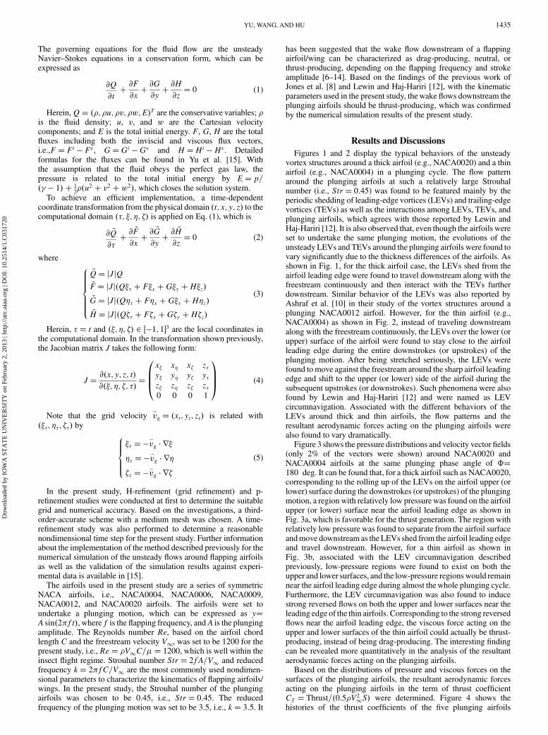
The governing equations for the fluid flow are the unsteadyNavier–Stokes equations in a conservation form, which can beexpressed as
@Q
@t� @F@x� @G@y� @H@z� 0 (1)
Herein,Q� ��; �u; �v; �w; E�T are the conservative variables; �is the fluid density; u, v, and w are the Cartesian velocitycomponents; and E is the total initial energy. F, G, H are the totalfluxes including both the inviscid and viscous flux vectors,i.e.,F� Fi � Fv, G�Gi � Gv and H �Hi �Hv. Detailedformulas for the fluxes can be found in Yu et al. [15]. Withthe assumption that the fluid obeys the perfect gas law, thepressure is related to the total initial energy by E� p=�� � 1� � 1
2��u2 � v2 �w2�, which closes the solution system.
To achieve an efficient implementation, a time-dependentcoordinate transformation from the physical domain �t; x; y; z� to thecomputational domain ��; �; �; �� is applied on Eq. (1), which is
@ ~Q
@�� @
~F
@x� @
~G
@y� @
~H
@z� 0 (2)
where8>>>><>>>>:
~Q� jJjQ~F� jJj�Q�� � F�x �G�y �H�z�~G� jJj�Q�� � F�x �G�y �H�z�~H � jJj�Q�� � F�x �G�y �H�z�
(3)
Herein, � � t and ��; �; �� 2 ��1; 1�3 are the local coordinates inthe computational domain. In the transformation shown previously,the Jacobian matrix J takes the following form:
J� @�x; y; z; t�@��; �; �; �� �
x� x� x� z�y� y� y� y�z� z� z� z�0 0 0 1
0BB@
1CCA (4)
Note that the grid velocity v*
g � �xt; yt; zt� is related with���; ��; ��� by
8>><>>:
�� ��v*
g � r��� ��v
*
g � r��� ��v
*
g � r�
(5)
In the present study, H-refinement (grid refinement) and p-refinement studies were conducted at first to determine the suitablegrid and numerical accuracy. Based on the investigations, a third-order-accurate scheme with a medium mesh was chosen. A time-refinement study was also performed to determine a reasonablenondimensional time step for the present study. Further informationabout the implementation of the method described previously for thenumerical simulation of the unsteady flows around flapping airfoilsas well as the validation of the simulation results against experi-mental data is available in [15].
The airfoils used in the present study are a series of symmetricNACA airfoils, i.e., NACA0004, NACA0006, NACA0009,NACA0012, and NACA0020 airfoils. The airfoils were set toundertake a plunging motion, which can be expressed as y�A sin�2�ft�, where f is the flapping frequency, andA is the plungingamplitude. The Reynolds number Re, based on the airfoil chordlength C and the freestream velocity V1, was set to be 1200 for thepresent study, i.e., Re� �V1C=�� 1200, which is well within theinsect flight regime. Strouhal number Str� 2fA=V1 and reducedfrequency k� 2�fC=V1 are the most commonly used nondimen-sional parameters to characterize the kinematics of flapping airfoils/wings. In the present study, the Strouhal number of the plungingairfoils was chosen to be 0.45, i.e., Str� 0:45. The reducedfrequency of the plunging motion was set to be 3.5, i.e., k� 3:5. It
has been suggested that the wake flow downstream of a flappingairfoil/wing can be characterized as drag-producing, neutral, orthrust-producing, depending on the flapping frequency and strokeamplitude [6–14]. Based on the findings of the previous work ofJones et al. [8] and Lewin and Haj-Hariri [12], with the kinematicparameters used in the present study, thewake flows downstream theplunging airfoils should be thrust-producing, which was confirmedby the numerical simulation results of the present study.
Results and Discussions
Figures 1 and 2 display the typical behaviors of the unsteadyvortex structures around a thick airfoil (e.g., NACA0020) and a thinairfoil (e.g., NACA0004) in a plunging cycle. The flow patternaround the plunging airfoils at such a relatively large Strouhalnumber (i.e., Str� 0:45) was found to be featured mainly by theperiodic shedding of leading-edge vortices (LEVs) and trailing-edgevortices (TEVs) as well as the interactions among LEVs, TEVs, andplunging airfoils, which agrees with those reported by Lewin andHaj-Hariri [12]. It is also observed that, even though the airfoils wereset to undertake the same plunging motion, the evolutions of theunsteady LEVs and TEVs around the plunging airfoils were found tovary significantly due to the thickness differences of the airfoils. Asshown in Fig. 1, for the thick airfoil case, the LEVs shed from theairfoil leading edge were found to travel downstream along with thefreestream continuously and then interact with the TEVs furtherdownstream. Similar behavior of the LEVs was also reported byAshraf et al. [10] in their study of the vortex structures around aplunging NACA0012 airfoil. However, for the thin airfoil (e.g.,NACA0004) as shown in Fig. 2, instead of traveling downstreamalong with the freestream continuously, the LEVs over the lower (orupper) surface of the airfoil were found to stay close to the airfoilleading edge during the entire downstrokes (or upstrokes) of theplunging motion. After being stretched seriously, the LEVs werefound tomove against the freestream around the sharp airfoil leadingedge and shift to the upper (or lower) side of the airfoil during thesubsequent upstrokes (or downstrokes). Such phenomena were alsofound by Lewin and Haj-Hariri [12] and were named as LEVcircumnavigation. Associated with the different behaviors of theLEVs around thick and thin airfoils, the flow patterns and theresultant aerodynamic forces acting on the plunging airfoils werealso found to vary dramatically.
Figure 3 shows the pressure distributions and velocity vector fields(only 2% of the vectors were shown) around NACA0020 andNACA0004 airfoils at the same plunging phase angle of ��180 deg. It can be found that, for a thick airfoil such as NACA0020,corresponding to the rolling up of the LEVs on the airfoil upper (orlower) surface during the downstrokes (or upstrokes) of the plungingmotion, a regionwith relatively low pressurewas found on the airfoilupper (or lower) surface near the airfoil leading edge as shown inFig. 3a, which is favorable for the thrust generation. The region withrelatively low pressure was found to separate from the airfoil surfaceandmove downstream as the LEVs shed from the airfoil leading edgeand travel downstream. However, for a thin airfoil as shown inFig. 3b, associated with the LEV circumnavigation describedpreviously, low-pressure regions were found to exist on both theupper and lower surfaces, and the low-pressure regionswould remainnear the airfoil leading edge during almost thewhole plunging cycle.Furthermore, the LEV circumnavigation was also found to inducestrong reversed flows on both the upper and lower surfaces near theleading edge of the thin airfoils. Corresponding to the strong reversedflows near the airfoil leading edge, the viscous force acting on theupper and lower surfaces of the thin airfoil could actually be thrust-producing, instead of being drag-producing. The interesting findingcan be revealed more quantitatively in the analysis of the resultantaerodynamic forces acting on the plunging airfoils.
Based on the distributions of pressure and viscous forces on thesurfaces of the plunging airfoils, the resultant aerodynamic forcesacting on the plunging airfoils in the term of thrust coefficientCT � Thrust=�0:5�V2
1S� were determined. Figure 4 shows thehistories of the thrust coefficients of the five plunging airfoils
YU, WANG, AND HU 1435
Dow
nloa
ded
by I
OW
A S
TA
TE
UN
IVE
RSI
TY
on
Febr
uary
2, 2
013
| http
://ar
c.ai
aa.o
rg |
DO
I: 1
0.25
14/1
.C03
1720

investigated in the present study. It can be seen that, although thethrust coefficients of the plunging airfoils were found to fluctuategreatly in each plunging cycles, the fluctuating amplitude of thethrust coefficients decreases as the thickness of the plunging airfoildecreases. Although all the airfoils were set to undertake the sameperiodic plunging motion, only the thrust coefficients of the thickerairfoils (e.g., NACA0020 and NACA0020 airfoils) were found to beperiodic, as expected. The thrust coefficients of the thinner airfoils(e.g., NACA0004 and NACA0006 airfoils) were found to becomeaperiodic even though the plunging motion of the airfoils is periodic.The aperiodic behavior of the flowfield around a plunging airfoil wasalso reported by Lewin and Haj-Hariri [12] with an elliptical airfoilplunging at a similar Strouhal numbers (e.g., Str 0:48) as that ofthe present study. It should also be noted that, for the thicker airfoils(e.g., NACA0012 or NACA0020), while the resultant aerodynamicforce acting on the plunging airfoils were found to be thrust-producing for most of the time in each plunging cycles (i.e., thrustcoefficient being positive), the resultant aerodynamic force couldalso become drag-producing (i.e., thrust coefficient becomingnegative) at some phase angles. However, the thrust coefficients ofthe thinner airfoils (e.g., NACA0004 or NACA0006) were found tobe positive almost in the entire plunging cycles, which indicates thatalmost no drag was experienced by the thinner airfoils during theplunging motion. This is believed to be closely related to the LEVcircumnavigation tomaintain low-pressure regions and reverse flowsnear the leading edges of the thinner airfoils.
To assess the role of viscous force in the thrust generation offlapping propulsion, the total thrusts acting on the plunging airfoils
were decomposed into two parts, i.e., one part contributed frompressure force, Tp �
Rpnx ds, and the other from the viscous force,
Tv �R�xxnx � xyny � xznz� ds, where denotes the viscous
stresses. Figure 5 shows the comparisons of the total thrustcoefficients (i.e., considering the contributions from both pressureand viscous forces) and the thrust coefficients based on thecontribution from pressure force only (i.e., ignoring the viscousforces) for NACA0020 and NACA0004 airfoils. Although theprofiles in solid lines represent the total thrust coefficients, theprofiles in dashed lines indicate the results based on the contributionfrom pressure force only. The differences between the solid anddashed lines would represent the contribution of viscous force on thethrust generation. It can be seen clearly that, compared with viscousforce, pressure force was found to play a dominant role in the thrustgeneration of flapping propulsion. It is also observed that thedifferences between the solid and dashed lines were found to becomelarger for the thinner airfoil (e.g., NACA0004), compared with thosefor the thicker airfoil case (e.g., NACA0020). This indicates that theeffects of viscous force on the thrust generation in flappingpropulsion would become stronger for the thinner airfoils.
To reveal the contribution of viscous force on the thrust generationof the plunging airfoils more clearly and quantitatively, the averagedtotal thrust coefficients of the plunging airfoils, hCTi, and thecontributions from pressure force, hCTPi, and viscous force, hCTV i,over plunging cycles were calculated. As revealed clearly from theresults listed in Table 1, the averaged thrust coefficients of theplunging airfoils vary significantly as the airfoil thickness changes.With the plunging kinematic parameters and the airfoil thickness
Fig. 1 Evolution of the unsteady vortex structures around NACA0020 airfoil in a plunging cycle.
1436 YU, WANG, AND HU
Dow
nloa
ded
by I
OW
A S
TA
TE
UN
IVE
RSI
TY
on
Febr
uary
2, 2
013
| http
://ar
c.ai
aa.o
rg |
DO
I: 1
0.25
14/1
.C03
1720

range used in the present study, a thicker airfoil was found to generatea larger averaged thrust when undertaking a same plunging motion.The finding was found to agree with the conclusion reported byAshraf et al. [10]. The results shown in Table 1 also confirmed that
pressure force would play a dominant role in the thrust generation offlapping propulsion. For the thicker airfoils (e.g., NACA0012 andNAC0020 airfoils), viscous force was found to be mainly drag-producing, and its effect was found to be very small (2:0%), which
Fig. 2 Evolution of the unsteady vortex structures around NACA0004 airfoil in a plunging cycle.
Fig. 3 Comparison of the pressure distributions and velocityfields aroundNACA0020 andNACA0004 airfoils at the phase angle of�� 180 deg in theplunging motion.
YU, WANG, AND HU 1437
Dow
nloa
ded
by I
OW
A S
TA
TE
UN
IVE
RSI
TY
on
Febr
uary
2, 2
013
| http
://ar
c.ai
aa.o
rg |
DO
I: 1
0.25
14/1
.C03
1720

is negligible. The finding can be used to explain why the traditionalinviscid model of Knoller–Betz effect (i.e., ignoring the viscouseffect) can be used to explain many phenomena associated withflapping propulsion. The drag-producing nature of viscous force forthick airfoils was found to agree with the results reported by Wang[11]. More interestingly, as revealed from the results given inTable 1, viscous force becomes thrust-producing, instead ofdrag-producing, for the thinner airfoils (e.g., NACA0006 andNACA0004). The contribution of viscous force to the thrustgeneration in flapping flight was found to become more and moresubstantial as the thickness of the plunging airfoil decreases (i.e.,13.6% for NACA0006 and up to 20.5% for NACA0004). This isbelieved to be closely related to the existence of reverseflows near theleading edges on both sides of the airfoil surfaces during almostwhole plunging cycles for the thinner airfoils, as shown clearly inFig. 3.
Conclusions
A numerical study was conducted to investigate the effects ofairfoil thickness on the thrust generation of plunging airfoils and toassess the contribution of viscous force to flapping propulsion. Aseries of commonly-used NACA symmetric airfoils were used in thepresent study to undertake a same plungingmotion at a lowReynoldsnumber of Re� 1200 with the plunging Strouhal number Str�0:45 and reduced frequency k� 3:5. It was found that, even thoughthe airfoils were set to undertake the same plunging motion, theevolutions of the vortex structures around the plunging airfoils andthe resultant aerodynamic forces acting on the airfoils varieddramatically due to the difference in airfoil thickness.
Although the leading-edge vortices (LEVs) of the thicker airfoils(e.g.,>9:0% thickness ratio for the present study)were found to shedperiodically and travel downstream along with the freestreamcontinuously, LEV circumnavigation was found for the thinnerairfoils (e.g., <9:0% thickness ratio) with LEVs stretched andremaining near the airfoil leading edges for most of time in theplunging cycles. Associated with the LEV circumnavigation, low-pressure regions and reverse flows were found to remain near theleading edge on both sides of the airfoils during almost wholeplunging cycles for the thinner airfoils. The different behaviors of theLEVs for the thick and thin airfoils were found to affect the resultantaerodynamic force acting on the plunging airfoils dramatically.Although the thrust generation of the plunging airfoils with largerthickness was found to be periodic as expected, the thrust generationof the thin airfoils was found to become aperiodic even though theplunging motion is periodic.
The present study also revealed that pressure force plays adominant role in the thrust generation of the plunging airfoils. Asexpected, viscous force contributes mainly to drag production, andits effect is almost negligible for the airfoils with relatively largethickness, which explains why the traditional inviscid model ofKnoller–Betz effect (i.e., ignoring the viscous effect) can be used toexplain many phenomena associated with flapping propulsion.Another important finding of the present study is the substantialcontribution of viscous force to the thrust generation for thin airfoils.The viscous force was found to become thrust-producing, instead ofdrag-producing, and it played a nonnegligible role in the thrustgeneration for the thin airfoils (i.e., producing up to 20.5%of the totalthrust for NACA0004 airfoil in the present study). The role change ofviscous force in the thrust generation of the plunging airfoils wasfound to be closely related to the dynamics of the unsteady vortexstructures around the plunging airfoils.
Acknowledgments
The authorswant to thank FengLiu of theUniversity ofCalifornia,Irvine, and JC Wu and Hong Liu of Shanghai Jiao Tong Universityfor helpful discussions related to the present study. The support of theNational Science Foundation under award number CBET-1064235is gratefully acknowledged.
References
[1] Knoller, R., “Die Gesetze des Luftwiderstandes,” Flug- und
Motortechnik, Vol. 3, No. 21, 1909, pp. 1–7.[2] Betz, A., “Ein Beitrag zur Erklaerung des Segelfluges,” Zeitschrift fuer
Flugtechnik und Motorluftschiffahrt, Vol. 3, 1912, pp. 269–270.[3] Katzmayr, R., “Effect of Periodic Changes of Angle of Attack on
Behavior of Airfoils,” NACATM 147, 1922.[4] Ober, S., “Note on the Kaztmayr Effect on Airfoil Drag,” NACA
TN 214, 1925.[5] von Kármán, T., and Burgers, J. M., Aerodynamic Theory: A General
Review of Progress, edited by W. F. Durand, Vol. 2, Springer, Berlin,1935.
[6] Koochesfahani, M. M., “Vortical Patterns in theWake of an OscillatingAirfoil,” AIAA Journal, Vol. 27, 1989, pp. 1200–1205.doi:10.2514/3.10246
[7] Dickinson, M. H., Lehmann, F. O., and Sane, S. P., “Wing Rotation andthe Aerodynamic Basis of Insect Flight,” Science, Vol. 284, 1999,pp. 1954–1960.doi:10.1126/science.284.5422.1954
Fig. 4 Histories of the thrust coefficients of the NACA symmetrical
airfoils in plunging motion.
Fig. 5 Comparison of the total thrust coefficients of the plunging
airfoils and the contributions from pressure force only.
Table 1 Averaged total thrust coefficients hCTiand the contributions from the pressure
force hCTPi and viscous force hCTv
i
Airfoil hCTi hCTP i hCTV i hCT�Vi=hCTiNACA0004 0.261 0.208 0.053 20.5%NACA0006 0.384 0.332 0.052 13.6%NACA0009 0.410 0.421 �0:011 �2:6%NACA0012 0.573 0.584 �0:011 �1:9%NACA0020 0.920 0.937 �0:017 �1:9%
1438 YU, WANG, AND HU
Dow
nloa
ded
by I
OW
A S
TA
TE
UN
IVE
RSI
TY
on
Febr
uary
2, 2
013
| http
://ar
c.ai
aa.o
rg |
DO
I: 1
0.25
14/1
.C03
1720

[8] Jones, K. D., Dohring, C. M., and Platzer, M. F., “Experimental andComputational Investigation of the Knoller–Betz Effect,” AIAA
Journal, Vol. 36, No. 7, 1998, pp. 1240–1246.doi:10.2514/2.505
[9] Platzer,M. F., Jones, K. D., Young, J., and Lai, J. C. S., “Flapping-WingAerodynamics: Progress and Challenges,” AIAA Journal, Vol. 46,No. 9, 2008, pp. 2136–2149.doi:10.2514/1.29263
[10] Ashraf,M.A., Yong, J., andLai, J. C. S., “ReynoldsNumber, Thicknessand Camber Effects on Flapping Airfoil Propulsion,” Journal of Fluidsand Structures, Vol. 27, 2011, pp. 145–160.doi:10.1016/j.jfluidstructs.2010.11.010
[11] Wang, Z. J., “Vortex Shedding and Frequency Selection in FlappingFlight,” Journal of Fluid Mechanics, Vol. 410, 2000, pp. 323–341.doi:10.1017/S0022112099008071
[12] Lewin, G. C., and Haj-Hariri, H., “Modeling Thrust Generation of aTwo-Dimensional HeavingAirfoil in a Viscous Flow,” Journal of FluidMechanics, Vol. 492, 2003, pp. 339–362.doi:10.1017/S0022112003005743
[13] Shyy, W., Lian, Y., Tang, J., Viieru, D., and Liu, H., Aerodynamics ofLow Reynolds Number Flyers, Cambridge Univ. Press, New York,2008.
[14] Hu, H., Clemons, L., and Igarashi, H., “An Experimental Study of theUnsteady Vortex Structures in the Wake of a Root-Fixed FlappingWing,” Experiments in Fluids, Vol. 51, No. 2, 2011, pp. 347–359.doi:10.1007/s00348-011-1052-z
[15] Yu, M. L., Wang, Z. J., and Hu, H., “A High-Order Spectral DifferenceMethod for Unstructured Dynamic Grids,” Computers and Fluids,Vol. 48, 2011, pp. 84–97.doi:10.1016/j.compfluid.2011.03.015
YU, WANG, AND HU 1439
Dow
nloa
ded
by I
OW
A S
TA
TE
UN
IVE
RSI
TY
on
Febr
uary
2, 2
013
| http
://ar
c.ai
aa.o
rg |
DO
I: 1
0.25
14/1
.C03
1720