application guide for potable water - gpsuk.com guide for potable water.pdf · application guide...
TRANSCRIPT

www.gpsuk.com T: 01480 442600 F: 01480 458829 E: [email protected]
APP001
Application Guide for Potable Water

Tel: +44 (0)1480 442600 Fax: +44 (0)1480 458829 Technical Support: +44 (0)1480 442620 2
Application Guide for Potable Water
Introduction 3
Product Range Overview 5
Excel Blue Pipe 7
Excel 3C Pipe 11
Excel 3CTH Pipe 12
PE80 Blue Pipe 14
Frialen Safety Fittings 16
Spigot Fittings 27
Pupped fittings 34
Accessories 42
Installation and technical Guidelines 43
Electrofusion Jointing Pipe Preparation & Procedures 44-46
Jointing Instructions for Electrofusion 47-51
Jointing Instructions for Large Diameter Electrofusion Couplers 52-54
Jointing Procedures for Top Loading Tapping Tees 55-56
Assembly & Operating Instructions for Friatop Clamping Unit for Branch Saddle without Underclamp 57-59
Butt Fusion Jointing Procedures 60-65
Flanged Connections 66-67
Repair Section Including Squeeze-Off 68-69
Duck Foot Bend Assembly 70
Handling and Storage 71-74
Pressure Ratings & Flow Characteristics 80-81
Pressure Testing 82
Design 83-87
Product Marking 88
Quality and Environmental Standards 89-90

Tel: +44 (0)1480 442600 Fax: +44 (0)1480 458829 Technical Support: +44 (0)1480 442620 Website: www.gpsuk.com Email: [email protected] 3
Complete polyethylene pipe solutions for potable water applications At the forefront of polyethylene pipe development for more than 60 years, GPS PE Pipe Systems offers a complete project support from initial system design through to commissioning.
Adopting a truly collaborative approach, GPS works with the entire supply chain to deliver a bespoke solution which best meet the needs of each individual scheme. From specification advice, through to delivering tailored training packages and on-site support during installation, the GPS team is with you through every step of the process.
More than just a manufacturer, GPS has an unrivalled reputation for forming long-lasting partnerships with its customers based on its service offering and unique added value propositions. This customer-led approach, combined with quality engineered product ranges, has made it the market leader it is today.
ApplicationsGPS potable water pipes and fittings are high quality, fully-approved and suitable for both new pipeline installations and renovation projects.
Features
• Available in both PE80 and PE100
• Sizes ranging from 20mm to 1200mm
• Available in standard SDR’s 11/17/21/26 (Other SDR’s are available on request)
• Standard coil diameters available in sizes up to 180mm
• Standard coil lengths of 50m and 100m (Other lengths are available on request)
• Standard stick lengths 6m and 12m (other lengths are available on request)
• A full range of compatible fittings
Benefits
• Flexible and light weight
• Resistance to corrosion
• Low friction and high flow rate
• Suitable for various installation techniques
• Cost savings in transportation and installation
• Excellent lifetime cost savings
• Security of continual and flexible supply to customers
• Reduction in carbon footprint
Approvals Fully compliant with Regulation 31/27/30
Kitemarked to BS EN 12201 (KM508224)
WRAS approved electrofusion and butt-fusion fittings (1603333)
WRAS approved electrofusion fittings (1505514)
WRAS approved spigot fittings (1208526)
Tel: +44 (0)1480 442600 Fax: +44 (0)1480 458829 Technical Support: +44 (0)1480 442620 4

Product Range OverviewDescription
Standard/ Approvals
MaterialSize
Range
Excel Blue Pipe
HDPE pipe for potable water supply below ground
EN 12201-2, WIS 4-32-17
Polyethylene 75mm - 1200mm
Excel 3CFactory cleaned HDPE pipe for potable water supply , which can be supplied with a factory fitted Towing Head
EN 12201-2, WIS 4-32-17
Polyethylene 90mm - 180mm
PE80 Blue Pipe
MDPE pipe for for potable water supply below ground
EN 12201-2, WIS 4-32-17
Polyethylene 20mm - 63mm
PE80 3CMDPE pipe for for potable water supply , which can be supplied with a factory fitted Towing Head
EN 12201-2, WIS 4-32-17
Polyethylene 32mm & 63mm
Electrofusion Fittings
Electrofusion fittings with a bar coding system for rapid and convenient jointing
EN 12201-3 Polyethylene 20mm - 1200mm
Spigot Fittings
Complete range of long spigot fittings suitable for electrofusion and butt fusion
EN 12201-3 Polyethylene 32m - 355mm
Pupped Fittings
Extended spigots suitable for electrofusion and butt-fusion jointing
EN 12201-3 Polyethylene 90mm - 710mm
AccessoriesBacking rings and gaskets suitable for water applications
EN 681-2 EPDM, GMS 63mm - 315mm
Tel: +44 (0)1480 442600 Fax: +44 (0)1480 458829 Technical Support: +44 (0)1480 442620 Website: www.gpsuk.com Email: [email protected] 5
Tel: +44 (0)1480 442600 Fax: +44 (0)1480 458829 Technical Support: +44 (0)1480 442620 6
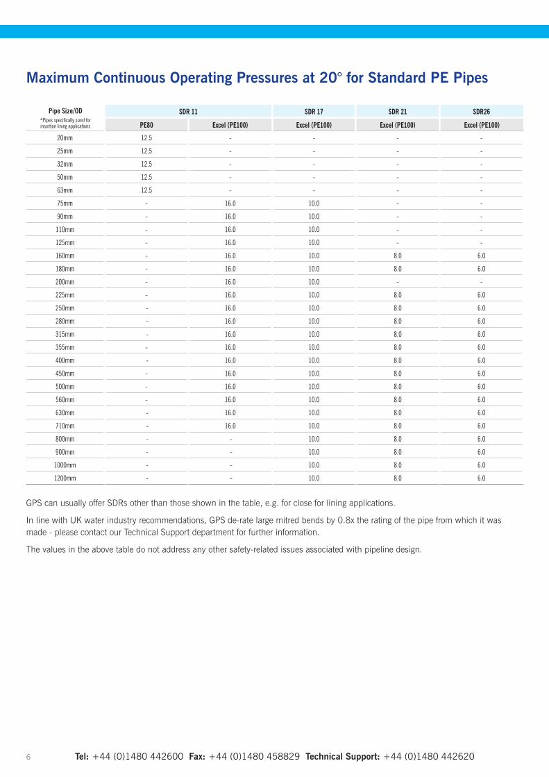
Maximum Continuous Operating Pressures at 20° for Standard PE Pipes
Pipe Size/OD*Pipes specifically sized for insertion lining applications
SDR 11 SDR 17 SDR 21 SDR26
PE80 Excel (PE100) Excel (PE100) Excel (PE100) Excel (PE100)
20mm 12.5 - - - -
25mm 12.5 - - - -
32mm 12.5 - - - -
50mm 12.5 - - - -
63mm 12.5 - - - -
75mm - 16.0 10.0 - -
90mm - 16.0 10.0 - -
110mm - 16.0 10.0 - -
125mm - 16.0 10.0 - -
160mm - 16.0 10.0 8.0 6.0
180mm - 16.0 10.0 8.0 6.0
200mm - 16.0 10.0 - -
225mm - 16.0 10.0 8.0 6.0
250mm - 16.0 10.0 8.0 6.0
280mm - 16.0 10.0 8.0 6.0
315mm - 16.0 10.0 8.0 6.0
355mm - 16.0 10.0 8.0 6.0
400mm - 16.0 10.0 8.0 6.0
450mm - 16.0 10.0 8.0 6.0
500mm - 16.0 10.0 8.0 6.0
560mm - 16.0 10.0 8.0 6.0
630mm - 16.0 10.0 8.0 6.0
710mm - 16.0 10.0 8.0 6.0
800mm - - 10.0 8.0 6.0
900mm - - 10.0 8.0 6.0
1000mm - - 10.0 8.0 6.0
1200mm - - 10.0 8.0 6.0
GPS can usually offer SDRs other than those shown in the table, e.g. for close for lining applications.
In line with UK water industry recommendations, GPS de-rate large mitred bends by 0.8x the rating of the pipe from which it was made - please contact our Technical Support department for further information.
The values in the above table do not address any other safety-related issues associated with pipeline design.

Size/OD(mm)
Length (m)
SDR 11 Code
SDR 17 Code
SDR 21 Code
SDR 26 Code
75 6 21 512 312 21 506 312 - - 12 21 527 312 21 507 312 - -
90 6 21 512 313 21 506 313 - - 12 21 527 313 21 507 313 - -
110 6 21 512 314 21 506 314 - - 12 21 527 314 21 507 314 - -
125 6 21 512 315 21 506 315 - - 12 21 527 315 21 507 315 - -
160 6 21 512 317 21 506 317 21 519 317 21 518 31712 21 527 317 21 507 317 21 539 317 21 528 317
180 6 21 512 318 21 506 318 21 519 318 21 518 31812 21 527 318 21 507 318 21 539 318 21 528 318
200 6 21 512 319 21 506 319 - - 12 21 527 319 21 507 319 - -
225 6 21 512 320 21 506 320 21 519 320 21 518 32012 21 527 320 21 507 320 21 539 320 21 528 320
250 6 21 512 321 21 506 321 21 519 321 21 518 32112 21 527 321 21 507 321 21 539 321 21 528 321
280 6 21 512 322 21 506 322 21 519 322 21 518 32212 21 527 322 21 507 322 21 539 322 21 528 322
315 6 21 512 323 21 506 323 21 519 323 21 518 32312 21 527 323 21 507 323 21 539 323 21 528 323
355 6 21 512 324 21 506 324 21 519 324 21 518 32412 21 527 324 21 507 324 21 539 324 21 528 324
400 6 21 512 325 21 506 325 21 519 325 21 518 32512 21 527 325 21 507 325 21 539 325 21 528 325
450 6 21 512 326 21 506 326 21 519 326 21 518 32612 21 527 326 21 507 326 21 539 326 21 528 326
500 6 21 512 327 21 506 327 21 519 327 21 518 32712 21 527 327 21 507 327 21 539 327 21 528 327
560 6 21 512 328 21 506 328 21 519 328 21 518 32812 21 527 328 21 507 328 21 539 328 21 528 328
630 6 21 512 329 21 506 329 21 519 329 21 518 32912 21 527 329 21 507 329 21 539 329 21 528 329
710 6 21 512 330 21 506 330 21 519 330 21 518 33012 21 527 330 21 507 330 21 539 330 21 528 330
800 6 - 21 506 332 21 519 332 21 518 33212 - 21 507 332 21 539 332 21 528 332
900 6 - 21 506 333 21 519 333 21 518 33312 - 21 507 333 21 539 333 21 528 333
1000 6 - 21 506 334 21 519 334 21 518 33412 - 21 507 334 21 539 334 21 528 334
1200 6 - 21 506 335 21 519 335 21 518 33512 - 21 507 335 21 539 335 21 528 335
SDR26 pipe can be suitable for low or zero pressure applications in favourable ground conditions. Please contact our Technical Support Department for further information. Other diameters, SDRs and lengths can be made to order subject to a minimum order value - please contact our Sales Office for further information GPS pipes manufactured to EN12201-2 are capable of withstanding repeated transient surge pressures of up to twice the rated pressure of the pipe.
Tel: +44 (0)1480 442600 Fax: +44 (0)1480 458829 Technical Support: +44 (0)1480 442620 Website: www.gpsuk.com Email: [email protected] 7
Excel Blue Pipe
• Co-extruded blue outer and black core PE100
• Available in sizes from 75mm to 1200mm
• Available in standard SDRs’ 11/17/21/26
• Standard stick lengths 6m and 12m (straight lengths upto 18 metres available on request)
• Compatible with GPS’ existing portfolio of fittings
• Fully compliant with Regulation 31/27/30
• Kitemarked to BS EN 12201 (KM508224)
• WRAS approved PE materials
Other diameters, SDRs and lengths can be made to order subject to a minimum order value - please contact our Sales Office for further information.
Straight Lengths
Excel Blue Pipe

Tel: +44 (0)1480 442600 Fax: +44 (0)1480 458829 Technical Support: +44 (0)1480 442620 Website: www.gpsuk.com Email: [email protected] 8
Size (mm)
Max OD
(mm)
SDR 11 SDR 17
Min t(mm)
Max t(mm)
Mean Weight(kg/m)
Mean Bore (mm)
Min t(mm)
Max t(mm)
Mean Weight(kg/m)
Mean Bore (mm)
75 75.5 6.8 7.6 1.5 60.9 4.5 5.1 1.0 65.790 90.6 8.2 9.2 2.1 72.9 5.4 6.1 1.5 78.8
110 110.7 10.0 11.1 3.2 89.3 6.6 7.4 2.2 96.4125 125.8 114 12.7 4.1 101.3 7.4 8.3 2.8 109.7160 161.0 14.6 16.2 6.7 129.7 9.5 10.6 4.6 140.4180 181.1 16.4 18.2 8.5 146.0 10.7 11.9 5.8 158.0200 201.2 18.2 20.2 10.5 162.2 11.9 13.2 7.1 175.5225 226.4 20.5 22.7 13.3 182.5 13.4 14.9 9.0 197.4250 251.5 22.7 25.1 16.3 203.0 14.8 16.4 11.1 219.6280 281.7 25.4 28.1 20.5 227.4 16.6 18.4 13.9 245.9315 316.9 28.6 31.6 25.9 255.8 18.7 20.7 17.6 276.6355 357.2 32.2 35.6 32.9 288.3 21.1 23.4 22.4 311.6276 402.4 36.3 40.1 41.8 324.8 23.7 26.2 28.3 351.3450 452.7 40.9 45.1 52.9 365.4 26.7 29.5 35.9 395.2500 503.0 45.4 50.1 65.2 406.0 29.7 32.8 44.3 439.0560 563.4 50.8 56.0 81.7 454.9 33.2 36.7 55.5 491.8630 633.8 57.2 63.1 103.6 511.6 37.4 41.3 70.3 553.2710 716.4 64.5 71.1 131.5 577.6 42.1 46.5 89.1 624.6800 807.2 72.6 80.0 167.1 651.0 47.4 52.3 113.1 703.9900 908.1 - - - - 53.3 58.8 142.9 792.0
1000 1009.0 - - - - 59.3 65.4 176.5 879.81200 1210.8 - - - - 71.1 78.4 254.5 1055.9
Size (mm)
Max OD
(mm)
SDR 21 SDR 26
Min t(mm)
Max t(mm)
Mean Weight(kg/m)
Mean Bore (mm)
Min t(mm)
Max t(mm)
Mean Weight(kg/m)
Mean Bore (mm)
75 75.5 3.6 4.1 0.8 67.6 - - - -90 90.6 4.3 4.9 1.2 81.1 3.5 4.0 1.0 82.8
110 110.7 5.3 6.0 1.8 99.1 4.2 4.8 1.4 101.4125 125.8 6.0 6.7 2.1 112.7 4.8 5.4 1.9 115.2160 161.0 7.7 8.6 3.7 144.2 6.2 7.0 3.1 147.3180 181.1 8.6 9.6 4.7 162.4 6.9 7.7 3.8 166.0200 201.2 9.6 10.7 5.8 180.3 7.7 8.6 4.7 184.3225 226.4 10.8 12.0 7.4 202.9 8.6 9.6 5.9 207.5250 251.5 11.9 13.2 9.0 225.7 9.6 10.7 7.4 230.5280 281.7 13.4 14.9 11.4 252.6 10.7 11.9 9.2 258.3315 316.9 15.0 16.6 14.3 284.4 12.1 13.5 11.7 290.4355 357.2 16.9 18.7 18.2 320.5 13.6 15.1 14.8 327.4400 402.4 19.1 21.2 23.2 360.9 15.3 17.0 18.7 368.9450 452.7 21.5 23.8 29.3 406.1 17.2 19.1 23.7 415.1500 503.0 23.9 26.4 36.1 451.2 19.1 21.2 29.2 461.2560 563.4 26.7 29.5 45.2 505.5 21.4 23.7 36.6 516.6630 633.8 30.0 33.1 57.1 568.8 24.1 26.7 46.4 581.1710 716.4 33.9 37.4 72.6 641.9 27.2 30.1 58.9 655.9800 807.2 38.1 42.1 92.1 723.4 30.6 33.8 74.7 739.2900 908.1 42.9 47.3 116.4 813.9 34.4 38.3 94.8 831.4
1000 1009.0 47.7 52.6 143.8 904.2 38.2 42.2 116.5 924.11200 1210.8 57.2 63.1 207.4 1085.1 45.9 50.6 167.8 1108.9
*SDR9 only. Wall thickness increased to give a lower SDR and more resistance to damage. GPS pipes, manufactured to BS EN 12201-2 standard, are capable of withstanding transient surge pressures of up to twice the rated pressure of the pipe.
Pipe Dimensions
Excel Blue Pipe
Website: www.gpsuk.com Email: [email protected] 9
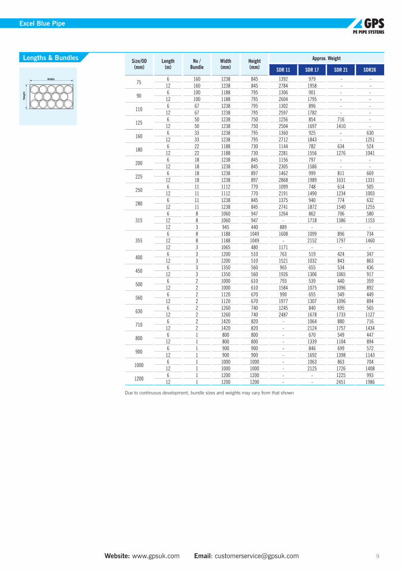
Size/OD (mm)
Length (m)
No / Bundle
Width (mm)
Height (mm)
Approx. Weight
SDR 11 SDR 17 SDR 21 SDR26
756 160 1238 845 1392 979 - -
12 160 1238 845 2784 1958 - -
906 100 1188 795 1306 901 - -
12 100 1188 795 2604 1795 - -
1106 67 1238 795 1302 896 - -
12 67 1238 795 2597 1782 - -
1256 50 1238 750 1256 854 716 -
12 50 1238 750 2504 1697 1410 -
1606 33 1238 795 1360 925 - 630
12 33 1238 795 2712 1843 - 1251
1806 22 1188 730 1144 782 634 524
12 22 1188 730 2281 1556 1276 1041
2006 18 1238 845 1156 797 - -
12 18 1238 845 2305 1586 - -
2256 18 1238 897 1462 999 811 669
12 18 1238 897 2868 1989 1631 1331
2506 11 1112 770 1099 748 614 505
12 11 1112 770 2191 1490 1234 1003
2806 11 1238 845 1375 940 774 632
12 11 1238 845 2741 1872 1540 1255
3156 8 1060 947 1264 862 706 580
12 8 1060 947 - 1718 1386 115312 3 945 440 889 - - -
3556 8 1188 1049 1608 1099 896 734
12 8 1188 1049 - 2152 1797 146012 3 1065 480 1171 - - -
4006 3 1200 510 763 519 424 347
12 3 1200 510 1521 1032 843 863
4506 3 1350 560 965 655 534 436
12 3 1350 560 1926 1306 1065 917
5006 2 1000 610 793 539 440 359
12 2 1000 610 1584 1075 1096 892
5606 2 1120 670 990 655 549 449
12 2 1120 670 1977 1307 1096 894
6306 2 1260 740 1245 840 695 565
12 2 1260 740 2487 1678 1733 1127
7106 2 1420 820 - 1064 880 716
12 2 1420 820 - 2124 1757 1434
8006 1 800 800 - 670 549 447
12 1 800 800 - 1339 1104 894
9006 1 900 900 - 846 699 572
12 1 900 900 - 1692 1398 1143
10006 1 1000 1000 - 1063 863 704
12 1 1000 1000 - 2125 1726 1408
12006 1 1200 1200 - - 1225 993
12 1 1200 1200 - - 2451 1986
Due to continuous development, bundle sizes and weights may vary from that shown
Lengths & Bundles
Excel Blue Pipe

Tel: +44 (0)1480 442600 Fax: +44 (0)1480 458829 Technical Support: +44 (0)1480 442620 Website: www.gpsuk.com Email: [email protected] 10
Excel Blue Pipe
Size (mm)
Length (m)
Blue Code
d(mm)
D(mm)
W(mm)
Approx.Weight (kg)
7550 21 559 312 1500 1900 310 73.0
100 21 560 312 1500 2300 310 145.0
9050 21 559 313 1800 2360 360 106.0
100 21 560 313 1800 2540 450 212.0
11050 21 559 314 2500 2700 450 160.0
100 21 560 314 2500 2900 570 318.0
12550 21 559 315 2500 3000 500 204.0
100 21 560 315 2500 3250 560 408.0
16050 21 559 317 3000 3900 490 337.0
100 21 560 317 3000 3900 650 670.0
18050 21 559 318 3000 3720 550 422.5
100 21 560 318 3000 3720 900 845.0
Size (mm)
Length (m)
Blue Code
d(mm)
D(mm)
W(mm)
Approx.Weight (kg)
7550 21 548 312 1800 2200 390 51.0
100 21 549 312 1800 2500 390 102.0
9050 21 548 313 2500 3100 270 69.5
100 21 549 313 2500 3300 360 139.0
11050 21 548 314 2500 2800 450 104.0
100 21 549 314 2500 3100 570 206.0
12550 21 548 315 2500 3500 400 133.0
100 21 549 315 2500 3750 500 266.0
16050 21 548 317 3000 3900 490 220.0
100 21 549 317 3000 3900 650 438.0
18050 21 548 318 3000 3720 550 274.5
100 21 549 318 3000 3720 900 549.0
Coil Lengths - SDR 11
Coil Lengths - SDR 17

Website: www.gpsuk.com Email: [email protected] 11
Excel 3C Pipe
Length (mm)
Length (m)
Blue Code
d(mm)
D(mm)
W(mm)
Approx.Weight (kg)
9050 21 845 313 1800 2360 360 106.075 21 862 313 1800 2420 380 157.0
100 21 860 313 1800 2540 450 212.0
11050 21 845 314 2500 2700 450 160.075 21 862 314 1800 2900 450 235.0
100 21 860 314 1800 2900 570 318.0
12550 21 845 315 2500 3000 500 204.075 21 862 315 2500 3200 450 302.0
100 21 860 315 2500 3250 560 408.0
16050 21 845 317 3000 3900 490 337.075 21 862 317 2500 3900 600 497.0
100 21 860 317 2500 3900 650 679.0
18050 21 845 318 3000 3720 550 423.075 21 862 318 3000 3700 790 626.0
100 21 860 318 3000 3720 900 845.0
Length (mm)
Length (m)
Blue Code
d(mm)
D(mm)
W(mm)
Approx.Weight (kg)
9050 21 846 313 2500 3100 270 69.575 21 847 313 2500 3080 380 108.0
100 21 849 313 2500 3300 360 139.0
11050 21 846 314 2500 2800 450 104.075 21 847 314 2500 3200 500 162.0
100 21 849 314 2500 3100 570 206.0
12550 21 846 315 2500 3500 400 133.075 21 847 315 2500 3200 450 204.0
100 21 849 315 2500 3750 500 266.0
16050 21 846 317 3000 3900 490 220.075 21 847 317 3000 3900 600 337.0
100 21 849 317 3000 3900 650 438.0
18050 21 846 318 3000 3720 550 275.075 21 847 318 3000 3700 790 423.0
100 21 849 318 3000 3720 900 549.0
Excel 3c Coils – SDR 11
Excel 3c Coils – SDR 17
Excel 3C Pipe
Excel 3C is a factory sealed PE100 pipe coil that is approved by the Secretary of State for installation without pre-chlorination. It can save up to seven days in installation time and vastly reduce the quantity of hypochlorite solution required. Excel 3C pipe can be supplied with a factory fitted Towing Head, ready to attach a towing shackle for immediate installation.
Excel 3C coils are available in SDR 11 and SDR 17, in sizes from 90mm to 180mm.
Features
• BS EN 12201 compliant pipe
• Factory sealed pipe ends
• Factory-clean pipe bore when delivered on site
• Regulations 31 and 27 approved coils for installation without pre-chlorination
• Optional integral factory-fitted Towing Head
Benefits
• Immediate installation from stock without lengthy pre-chlorination
• High installation productivity compared to unsealed coils
• Significant installation cost savings
• Kinder to the environment with reduced chlorine use
• Fewer visits to site needed – reduced traffic disruption

Tel: +44 (0)1480 442600 Fax: +44 (0)1480 458829 Technical Support: +44 (0)1480 442620 12
Excel 3CTH Pipe
Length (mm)
Length (m)
Blue Code
d(mm)
D(mm)
W(mm)
Approx.Weight (kg)
90
50 21 850 313 1800 2360 360 106.0
75 21 851 313 1800 2420 380 157.0
100 21 852 313 1800 2540 450 212.0
110
50 21 850 314 2500 2700 450 160.0
75 21 851 314 1800 2900 450 235.0
100 21 852 314 1800 2900 570 318.0
125
50 21 850 315 2500 3000 500 204.0
75 21 851 315 2500 3200 450 302.0
100 21 852 315 2500 3250 560 408.0
160
50 21 850 317 3000 3900 490 337.0
75 21 851 317 2500 3900 600 497.0
100 21 852 317 2500 3900 650 679.0
180
50 21 850 318 3000 3720 550 423.0
75 21 851 318 3000 3700 790 626.0
100 21 852 318 3000 3720 900 845.0
Excel 3CTH Coils – SDR 11
Excel 3CTH Pipe
Excel 3CTH pipes are excel 3C pipes supplied complete with a factory fitted Towing Head, ready to be attached to a towing shackle for immediate installation. Unlike most conventional detachable towing heads, the GPS Towing Head is integral to the pipe. This removes the risk of installation failure resulting from the towing head being pulled away and ensures that the pipe stays sealed from the point of manufacture and throughout the whole installation process.
A fast, simple and extremely reliable method of attaching a pulling device to a plastic pipe, the GPS Towing Head lowers overall installation costs by reducing installation time and the risk of a towing head installation failure.
Features
• Safe and robust design – the weld’s yield strength is greater than the pipe’s yield strength
• Factory welded onto the pipe for complete integrity
• Excel 3c pipe remains completely sealed from factory to installation
• No on site preparation required – just hook the shackle
• No additional fixtures or fittings required
• Manufactured in PE100
• Suitable for all installation techniques where a towing head is required
Benefits
• Ease of use
• Reduction in installation time
• No installation failure due to towing
• head detaching from pipe
• Cost savings due to reduced installation
• time and improved productivity
• No risk of contamination from the ingress of water or debris
Note: GPS PIPES manufactured to EN12201-2 are capable of withstanding repeated transient surge pressures of up to twice the rated pressure of the pipe.

Tel: +44 (0)1480 442600 Fax: +44 (0)1480 458829 Technical Support: +44 (0)1480 442620 Website: www.gpsuk.com Email: [email protected] 13
Excel 3CTH Pipe
Length (mm)
Length (m)
Blue Code
d(mm)
D(mm)
W(mm)
Approx.Weight (kg)
90
50 21 853 313 2500 3100 270 69.5
75 21 854 313 2500 3080 380 108.0
100 21 855 313 2500 3300 360 139.0
110
50 21 853 314 2500 2800 450 104.0
75 21 854 314 2500 3200 500 162.0
100 21 855 314 2500 3100 570 206.0
125
50 21 853 315 2500 3500 400 133.0
75 21 854 315 2500 3200 450 204.0
100 21 855 315 2500 3750 500 266.0
160
50 21 853 317 3000 3900 490 220.0
75 21 854 317 3000 3900 600 337.0
100 21 855 317 3000 3900 650 438.0
180
50 21 853 318 3000 3720 550 275.0
75 21 854 318 3000 3700 790 423.0
100 21 855 318 3000 3720 900 549.0
Excel 3CTH Coils – SDR 17
Tel: +44 (0)1480 442600 Fax: +44 (0)1480 458829 Technical Support: +44 (0)1480 442620 14
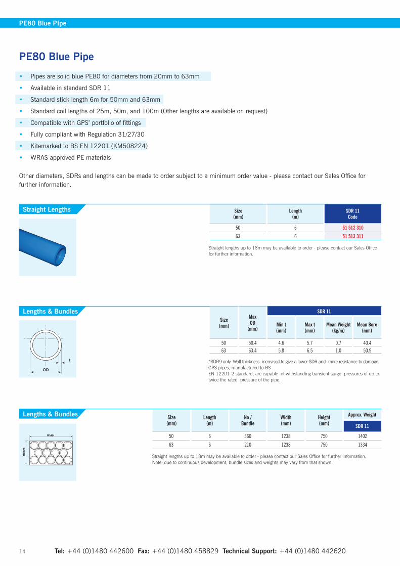
Size (mm)
Length (m)
SDR 11 Code
50 6 51 512 310
63 6 51 513 311
Straight lengths up to 18m may be available to order - please contact our Sales Office for further information.
PE80 Blue Pipe
• Pipes are solid blue PE80 for diameters from 20mm to 63mm
• Available in standard SDR 11
• Standard stick length 6m for 50mm and 63mm
• Standard coil lengths of 25m, 50m, and 100m (Other lengths are available on request)
• Compatible with GPS’ portfolio of fittings
• Fully compliant with Regulation 31/27/30
• Kitemarked to BS EN 12201 (KM508224)
• WRAS approved PE materials
Other diameters, SDRs and lengths can be made to order subject to a minimum order value - please contact our Sales Office for further information.
Straight Lengths
PE80 Blue PIpe
Size (mm)
Length (m)
No / Bundle
Width (mm)
Height (mm)
Approx. Weight
SDR 11
50 6 360 1238 750 1402
63 6 210 1238 750 1334
Straight lengths up to 18m may be available to order - please contact our Sales Office for further information. Note: due to continuous development, bundle sizes and weights may vary from that shown.
Lengths & Bundles
Lengths & BundlesSize (mm)
Max OD
(mm)
SDR 11
Min t(mm)
Max t(mm)
Mean Weight(kg/m)
Mean Bore (mm)
50 50.4 4.6 5.7 0.7 40.463 63.4 5.8 6.5 1.0 50.9
*SDR9 only. Wall thickness increased to give a lower SDR and more resistance to damage. GPS pipes, manufactured to BS EN 12201-2 standard, are capable of withstanding transient surge pressures of up to twice the rated pressure of the pipe.
Website: www.gpsuk.com Email: [email protected] 15
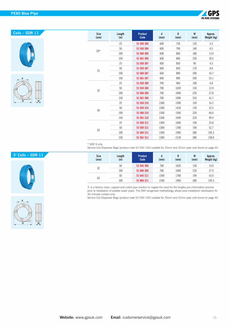
PE80 Blue PIpe
Size (mm)
Length (m)
Product Code
d(mm)
D(mm)
W(mm)
Approx.Weight (kg)
20*
25 51 558 306 600 750 120 3.3
50 51 559 306 600 790 140 6.5
100 51 560 306 600 860 180 13.0
150 51 561 306 600 860 250 18.5
25
25 51 558 307 600 830 90 4.3
50 51 559 307 600 820 170 8.4
100 51 560 307 600 890 200 16.7
150 51 561 307 600 890 290 25.1
32
25 51 558 308 700 960 100 6.8
50 51 559 308 700 1020 150 13.9
100 51 560 308 700 1090 220 27.8
150 51 561 308 700 1090 310 41.7
50
25 51 558 310 1300 1500 150 16.2
50 51 559 310 1300 1410 150 32.5
100 51 560 310 1300 1560 220 66.6
150 51 561 310 1300 1690 220 99.9
63
25 51 558 311 1300 1600 190 25.8
50 51 559 311 1300 1780 190 52.7
100 51 560 311 1300 1960 280 105.3
150 51 561 311 1300 2130 280 158.0
* SDR 9 only Service Coil Dispenser Bags (product code 53 590 100) suitable for 25mm and 32mm pipe coils found on page 40.
Size (mm)
Length (m)
Product Code
d(mm)
D(mm)
W(mm)
Approx.Weight (kg)
3250 51 845 308 700 1020 150 14.0
100 51 860 308 700 1090 220 27.9
6350 51 845 311 1300 1780 190 53.0
100 51 860 311 1300 1960 280 105.5
3c is a factory clean, capped and coiled pipe solution to negate the need for the lengthy pre-chlorination process prior to installation of potable water pipes. The DWI recognised methodology allows post-installation sterilisation for 30 minutes contact only. Service Coil Dispenser Bags (product code 53 590 100) suitable for 25mm and 32mm pipe coils found on page 40.
Coils – SDR 11
3c Coils – SDR 11

Tel: +44 (0)1480 442600 Fax: +44 (0)1480 458829 Technical Support: +44 (0)1480 442620 16
Size(mm) SDR Product
CodeD
(mm)L
(mm)Weight
(kg)
FusionTime(Sec)
CoolingTime
(mins)
20 11 FL 612 680 33 60 0.1 25 525 11 FL 612 681 37 78 0.1 30 532 11 FL 612 682 45 78 0.1 26 540 11 FL 612 683 54 86 0.1 46 750 11 FL 612 684 68 98 0.2 42 763 11 FL 612 685 82 110 0.3 36 775 11 FL 612 686 98 122 0.4 barcode read only90 11 FL 612 687 114 138 0.5 65 10
110 11 FL 612 688 137 159 0.7 120 10125 11 FL 612 689 156 172 1.0 225 15140 11 FL 612 690 174 184 1.3 280 15160 11 FL 612 691 199 190 1.8 360 20
Maximum continuous operating pressure SDR 11 - 16 bar water (EN 12201-3).Manual fusion times are based on 39.5 volt fusion boxes. 4.0mm terminal pins.
Size(mm) SDR Product
CodeD
(mm)L
(mm)Weight
(kg)
FusionTime(Sec)
CoolingTime
(mins)
180 11 FL 612 672 220 210 2.1 480 20200 11 FL 612 673 247 220 2.8 550 20225 11 FL 612 674 277 236 4.0 550 20250 11 FL 612 675 315 246 5.8 620 30280 11 FL 615 073 347 285 7.8 897 30315 11 FL 612 670 390 300 10.1 1250 30355 11 FL 615 074 445 300 14.6 1130 30400 11 FL 615 075 500 320 20.8 750 40450 11 FL 615 076 560 340 30.0 barcode read only500 11 FL 615 124 630 360 40.0 barcode read only
56011 FL 613 312 715 380 55.0 barcode read only17 FL 615 706 630 380 24.2 barcode read only
63011 FL 616 269 810 420 79.6 barcode read only17 FL 615 726 710 420 34.9 barcode read only
71011 FL 616 313 900 420 101.0 barcode read only17 FL 615 994 800 460 47.5 barcode read only
80011 FL 616 314 1000 500 138.8 barcode read only17 FL 616 290 900 500 65.9 barcode read only
90011 FL 616 440 1130 600 210.3 barcode read only17 FL 616 345 1024 500 91.5 barcode read only
1000* 17 FL 616 403 1130 610 128.0 barcode read only1200* 17 FL 616 416 1356 670 205.0 barcode read only
Maximum continuous operating pressure SDR 11 - 16 bar water (EN 12201-3). Maximum continuous operating pressure SDR 17 - 10 bar water (EN 12201-3). Couplers from 400mm upwards are bifilament - have separate fusion zones. Couplers from 355mm upwards have external reinforcement Manual fusion times are based on 39.5 volt fusion boxes. 4.0mm terminal pins *Can only be installed using the FRIAMAT XL control box 4.0mm terminal pins.
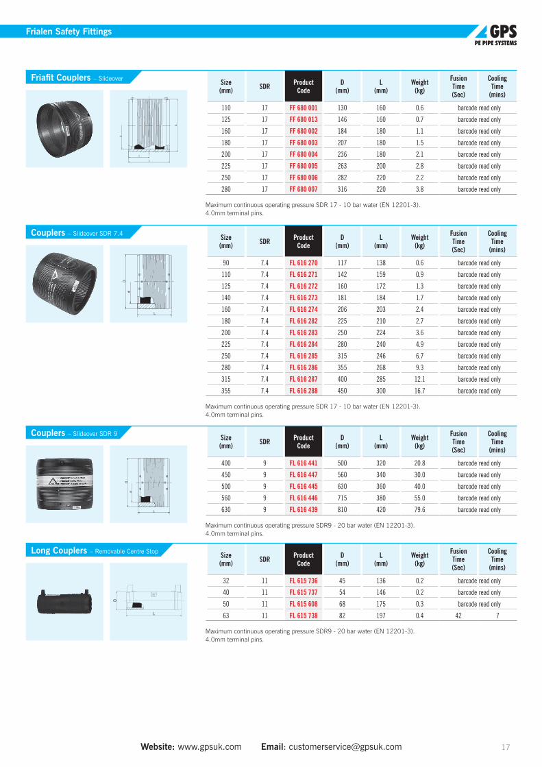
Frialen Safety Fittings Electrofusion Fittings for Water
GPS Frialen fittings, Spigot fittings and Pupped fittings are approved and compatible with Excel (PE100) & PE80 for using in potable water pipelines. Please go to www.gpsuk.com or email [email protected] for further support.
Couplers – Removable Centre Stop
Couplers – Slideover SDR 11
Frialen Safety Fittings
Website: www.gpsuk.com Email: [email protected] 17
Size(mm) SDR Product
CodeD
(mm)L
(mm)Weight
(kg)
FusionTime(Sec)
CoolingTime
(mins)
110 17 FF 680 001 130 160 0.6 barcode read only
125 17 FF 680 013 146 160 0.7 barcode read only
160 17 FF 680 002 184 180 1.1 barcode read only
180 17 FF 680 003 207 180 1.5 barcode read only
200 17 FF 680 004 236 180 2.1 barcode read only
225 17 FF 680 005 263 200 2.8 barcode read only
250 17 FF 680 006 282 220 2.2 barcode read only
280 17 FF 680 007 316 220 3.8 barcode read only
Maximum continuous operating pressure SDR 17 - 10 bar water (EN 12201-3). 4.0mm terminal pins.
Size(mm) SDR Product
CodeD
(mm)L
(mm)Weight
(kg)
FusionTime(Sec)
CoolingTime
(mins)
90 7.4 FL 616 270 117 138 0.6 barcode read only
110 7.4 FL 616 271 142 159 0.9 barcode read only
125 7.4 FL 616 272 160 172 1.3 barcode read only
140 7.4 FL 616 273 181 184 1.7 barcode read only
160 7.4 FL 616 274 206 203 2.4 barcode read only
180 7.4 FL 616 282 225 210 2.7 barcode read only
200 7.4 FL 616 283 250 224 3.6 barcode read only
225 7.4 FL 616 284 280 240 4.9 barcode read only
250 7.4 FL 616 285 315 246 6.7 barcode read only
280 7.4 FL 616 286 355 268 9.3 barcode read only
315 7.4 FL 616 287 400 285 12.1 barcode read only
355 7.4 FL 616 288 450 300 16.7 barcode read only
Maximum continuous operating pressure SDR 17 - 10 bar water (EN 12201-3). 4.0mm terminal pins.
Size(mm) SDR Product
CodeD
(mm)L
(mm)Weight
(kg)
FusionTime(Sec)
CoolingTime
(mins)
400 9 FL 616 441 500 320 20.8 barcode read only
450 9 FL 616 447 560 340 30.0 barcode read only
500 9 FL 616 445 630 360 40.0 barcode read only
560 9 FL 616 446 715 380 55.0 barcode read only
630 9 FL 616 439 810 420 79.6 barcode read only
Maximum continuous operating pressure SDR9 - 20 bar water (EN 12201-3). 4.0mm terminal pins.
Size(mm) SDR Product
CodeD
(mm)L
(mm)Weight
(kg)
FusionTime(Sec)
CoolingTime
(mins)
32 11 FL 615 736 45 136 0.2 barcode read only
40 11 FL 615 737 54 146 0.2 barcode read only
50 11 FL 615 608 68 175 0.3 barcode read only
63 11 FL 615 738 82 197 0.4 42 7
Maximum continuous operating pressure SDR9 - 20 bar water (EN 12201-3). 4.0mm terminal pins.
L
D
t
d
Friafit Couplers – Slideover
Couplers – Slideover SDR 7.4
Couplers – Slideover SDR 9
Long Couplers – Removable Centre Stop
Frialen Safety Fittings
L
D
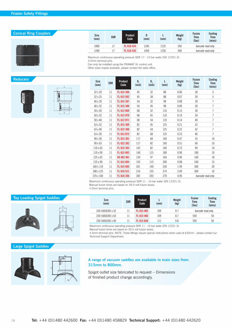
A range of vacuum saddles are available in main sizes from 315mm to 800mm.
Spigot outlet size fabricated to request – Dimensions of finished product change accordingly.
Tel: +44 (0)1480 442600 Fax: +44 (0)1480 458829 Technical Support: +44 (0)1480 442620 18
Frialen Safety Fittings
Size (mm) SDR Product
CodeL
(mm)Weight
(kg)
FusionTime(Sec)
CoolingTime
(mins)
250-560(630) x 32 11 FL 615 465 109 0.7 barcode read only
250-560(630) x 63 11 FL 615 466 109 0.7 550 50
250-560(630) x 90 11 FL 615 850 111 0.8 550 50
Maximum continuous operating pressure SDR 11 - 16 bar water (EN 12201-3). Manual fusion times are based on 39.5 volt fusion boxes. 4.0mm terminal pins. NOTE: These fittings require special instructions when used at 630mm - please contact our Technical Support Department.
Top Loading Spigot Saddles
Large Spigot Saddles
Size(mm) SDR Product
CodeD
(mm)L
(mm)Weight
(kg)
FusionTime(Sec)
CoolingTime
(mins)
1000 17 FL 616 434 1245 1125 350 barcode read only1200 17 FL 616 435 1450 1250 500 barcode read only
Maximum continuous operating pressure SDR 17 - 10 bar water (EN 12201-3). 4.0mm terminal pins. Can only be installed using the FRIAMAT XL control unit. Other sizes maybe available, please contact the sales office.
Conical Ring Couplers
Size(mm) SDR Product
CodeD1
(mm)D2
(mm)L
(mm)Weight
(kg)
FusionTime(Sec)
CoolingTime
(mins)
32 x 20 11 FL 615 386 45 32 88 0.06 30 532 x 25 11 FL 615 502 45 38 88 0.07 30 540 x 20 11 FL 615 387 54 32 98 0.08 30 740 x 32 11 FL 615 388 54 45 98 0.09 30 750 x 20 11 FL 612 069 68 32 110 0.13 30 750 x 32 11 FL 612 070 68 45 110 0.14 34 750 x 40 11 FL 612 071 68 54 110 0.14 40 763 x 32 11 FL 615 389 82 45 125 0.21 32 763 x 40 11 FL 615 390 82 54 125 0.22 42 763 x 50 11 FL 612 072 82 68 125 0.23 46 790 x 50 11 FL 615 391 117 68 160 0.47 55 1090 x 63 11 FL 615 392 117 82 160 0.51 60 10
110 x 63 11 FL 615 393 142 82 160 0.73 90 10110 x 90 11 FL 615 693 140 115 180 0.90 180 10125 x 63 11 69 402 461 159 97 164 0.96 160 18125 x 90 11 FL 615 694 155 115 200 0.98 240 15
160 x 110 11 FL 615 695 201 140 230 1.99 300 20180 x 125 11 FL 616 511 216 155 274 2.60 300 16225 x 160 11 FL 616 356 282 203 270 4.90 barcode read only
Maximum continuous operating pressure SDR 11 - 16 bar water (EN 12201-3). Manual fusion times are based on 39.5 volt fusion boxes. 4.0mm terminal pins.
Reducers

Website: www.gpsuk.com Email: [email protected] 19
Frialen Safety Fittings
Size(mm) SDR Product
CodeL
(mm)Drilling (mm)
Weight (kg)
FusionTime(Sec)
CoolingTime
(mins)
63 x 32 11 FL 612 757 100 20 0.4 barcode read only63 x 50 11 FL 612 759 113 36 0.4 barcode read only75 x 50 11 FL 615 020 82 36 0.5 barcode read only90 x 32 11 FL 615 285 103 20 0.7 barcode read only90 x 63 11 FL 612 819 103 46 0.8 barcode read only
110 x 32 11 FL 615 334 125 20 0.8 barcode read only110 x 50 11 FL 615 031 132 36 0.8 barcode read only110 x 63 11 FL 612 760 150 46 0.9 barcode read only110 x 90 11 FL 615 411 115 65 1.0 barcode read only125 x 32 11 FL 615 087 109 20 1.0 barcode read only125 x 63 11 FL 612 761 109 46 1.0 barcode read only125 x 90 11 FL 615 412 116 65 1.1 barcode read only
125 x 110 11 FL 615 584 116 84 1.2 barcode read only160 x 32 11 FL 612 886 126 20 1.5 barcode read only160 x 63 11 FL 612 762 140 46 1.6 barcode read only160 x 90 11 FL 615 413 140 65 1.7 barcode read only
160 x 110 11 FL 615 739 140 84 1.8 barcode read only160 x 125 11 FL 615 585 140 95 1.9 barcode read only180 x 63 11 FL 612 763 109 46 1.2 barcode read only180 x 90 11 FL 615 414 116 65 1.9 barcode read only
180 x 110 11 FL 615 948 136 84 2.1 barcode read only180 x 125 11 FL 615 740 141 95 2.2 barcode read only200 x 63 11 FL 612 764 109 46 1.3 barcode read only225 x 63 11 FL 612 765 109 46 1.3 barcode read only225 x 90 11 FL 615 415 130 65 2.0 barcode read only
225 x 110 11 FL 616 044 140 84 2.0 barcode read only225 x 125 11 FL 616 045 146 95 2.2 barcode read only225 x 160 11 FL 616 046 157 123 2.6 barcode read only
Maximum continuous operating pressure SDR 11 - 16 bar water (EN 12201-3). 4.0mm terminal pins.
Size(mm) SDR Product
CodeD
(mm)L
(mm)L1
(mm)Weight
(kg)
Fusion Time (main)(Sec)
Fusion Time (branch)
(Sec)
CoolingTime
(mins)
25 11 FL 616 338 36 108 110 0.2 30 - 5
32 11 FL 615 719 44 116 131 0.2 28 - 5
40 11 FL 615 720 53 146 151 0.3 45 - 7
50 11 FL 615 721 67 175 186 0.5 34 - 7
63 11 FL 615 722 81 197 203 0.8 42 - 7
Maximum continuous operating pressure SDR 11 - 16 bar water (EN 12201-3). Manual fusion times are based on 39.5 volt fusion boxes. 4.0mm terminal pins.
Size(mm) SDR Product
CodeD
(mm)L
(mm)L1
(mm)Weight
(kg)
Fusion Time (main)(Sec)
Fusion Time (branch)
(Sec)
CoolingTime
(mins)
75 11 FL 612 165 96 278 187 1.0 72 80 10
90 11 FL 612 166 117 305 211 1.7 90 90 10
110 11 FL 612 167 142 355 248 2.6 140 160 10
125 11 FL 612 168 160 384 272 3.6 180 200 15
160 11 FL 615 277 200 430 315 5.8 400 400 20
180 11 FL 615 691 228 480 354 8.0 440 440 20
200 11 FL 616 266 251 550 400 11.1
225 11 FL 615 692 280 580 430 13.9 540 540 20
Maximum continuous operating pressure SDR 11 - 16 bar water (EN 12201-3). Manual fusion times are based on 39.5 volt fusion boxes. 4.0mm terminal pins.
Under Clamp Spigot Saddles
Equal Tees
Equal Tees
barcode read only
Tel: +44 (0)1480 442600 Fax: +44 (0)1480 458829 Technical Support: +44 (0)1480 442620 20
Size(mm) SDR Product
CodeD
(mm)L
(mm)Weight
(kg)
FusionTime(Sec)
CoolingTime
(mins)
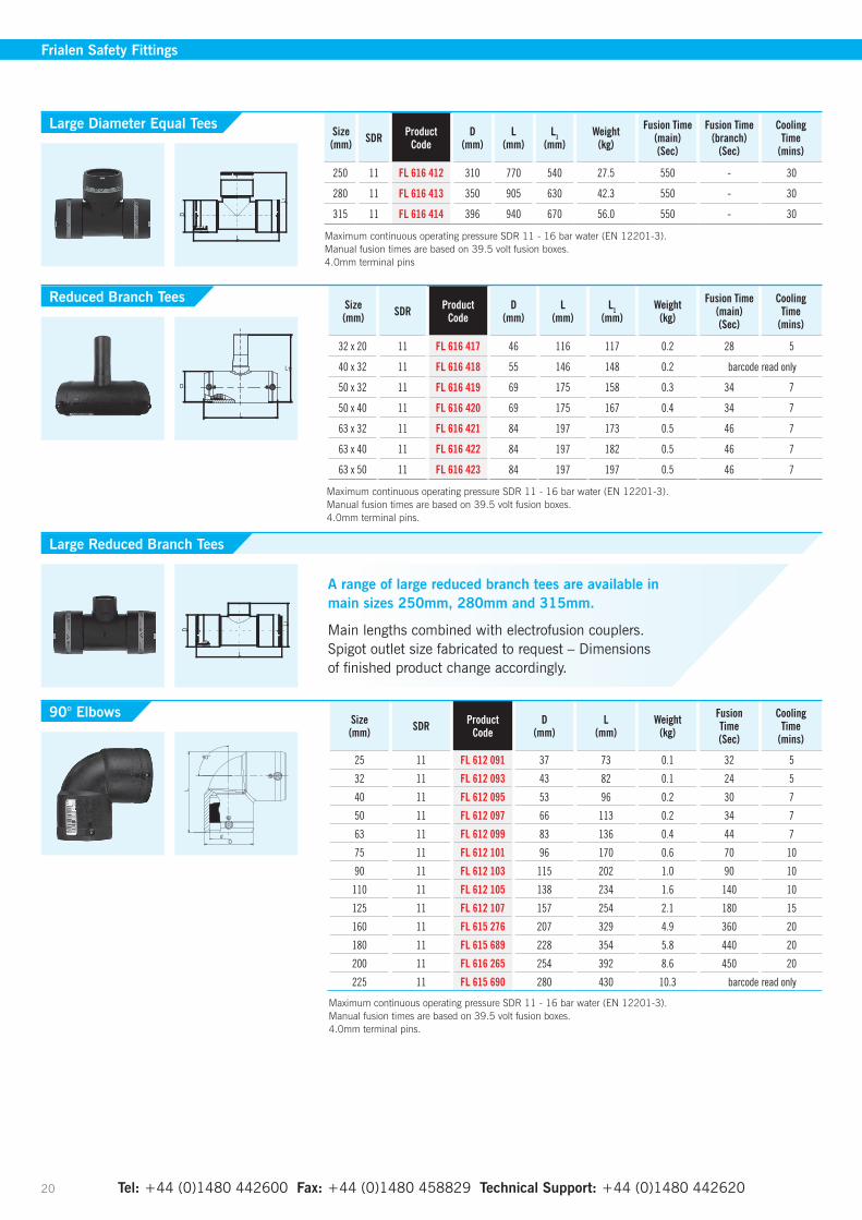
25 11 FL 612 091 37 73 0.1 32 5
32 11 FL 612 093 43 82 0.1 24 5
40 11 FL 612 095 53 96 0.2 30 7
50 11 FL 612 097 66 113 0.2 34 7
63 11 FL 612 099 83 136 0.4 44 7
75 11 FL 612 101 96 170 0.6 70 10
90 11 FL 612 103 115 202 1.0 90 10
110 11 FL 612 105 138 234 1.6 140 10
125 11 FL 612 107 157 254 2.1 180 15
160 11 FL 615 276 207 329 4.9 360 20
180 11 FL 615 689 228 354 5.8 440 20
200 11 FL 616 265 254 392 8.6 450 20
225 11 FL 615 690 280 430 10.3 barcode read only
Maximum continuous operating pressure SDR 11 - 16 bar water (EN 12201-3). Manual fusion times are based on 39.5 volt fusion boxes. 4.0mm terminal pins.
90° Elbows
Frialen Safety Fittings
Size(mm) SDR Product
CodeD
(mm)L
(mm)L1
(mm)Weight
(kg)
Fusion Time (main)(Sec)
Fusion Time (branch)
(Sec)
CoolingTime
(mins)
250 11 FL 616 412 310 770 540 27.5 550 - 30
280 11 FL 616 413 350 905 630 42.3 550 - 30
315 11 FL 616 414 396 940 670 56.0 550 - 30
Maximum continuous operating pressure SDR 11 - 16 bar water (EN 12201-3). Manual fusion times are based on 39.5 volt fusion boxes. 4.0mm terminal pins
Size(mm) SDR Product
CodeD
(mm)L
(mm)L1
(mm)Weight
(kg)
Fusion Time (main)(Sec)
CoolingTime
(mins)
32 x 20 11 FL 616 417 46 116 117 0.2 28 5
40 x 32 11 FL 616 418 55 146 148 0.2 barcode read only
50 x 32 11 FL 616 419 69 175 158 0.3 34 7
50 x 40 11 FL 616 420 69 175 167 0.4 34 7
63 x 32 11 FL 616 421 84 197 173 0.5 46 7
63 x 40 11 FL 616 422 84 197 182 0.5 46 7
63 x 50 11 FL 616 423 84 197 197 0.5 46 7
Maximum continuous operating pressure SDR 11 - 16 bar water (EN 12201-3). Manual fusion times are based on 39.5 volt fusion boxes. 4.0mm terminal pins.
Large Diameter Equal Tees
Reduced Branch Tees
Large Reduced Branch Tees
A range of large reduced branch tees are available in main sizes 250mm, 280mm and 315mm.
Main lengths combined with electrofusion couplers. Spigot outlet size fabricated to request – Dimensions of finished product change accordingly.

Website: www.gpsuk.com Email: [email protected] 21
Size(mm) SDR Product
CodeD
(mm)L
(mm)Weight
(kg)
FusionTime(Sec)
CoolingTime
(mins)
250 11 FL 616 408 310 534 19.1 550 30
280 11 FL 616 409 350 621 27.5 550 30
315 11 FL 616 410 396 677 40.0 550 30
Maximum continuous operating pressure SDR 11 - 16 bar water (EN 12201-3). Manual fusion times are based on 39.5 volt fusion boxes. 4.0mm terminal pins
Size(mm) SDR Product
CodeD
(mm)L
(mm)Weight
(kg)
FusionTime(Sec)
CoolingTime
(mins)
32 11 FL 612 092 43 102 0.1 24 5
40 11 FL 612 094 54 120 0.2 30 7
50 11 FL 612 096 66 136 0.2 34 7
63 11 FL 612 098 82 158 0.3 44 7
75 11 FL 612 100 96 198 0.6 70 10
90 11 FL 612 102 115 232 0.9 90 10
110 11 FL 612 104 138 265 1.3 140 10
125 11 FL 612 106 157 279 1.8 180 15
160 11 FL 615 275 207 377 4.4 360 20
180 11 FL 615 687 228 382 4.7 440 20
200 11 FL 616 264 254 415 6.8 450 20
225 11 FL 615 688 280 450 8.3 barcode read only
Maximum continuous operating pressure SDR 11 - 16 bar water (EN 12201-3). Manual fusion times are based on 39.5 volt fusion boxes. 4.0mm terminal pins.
Size(mm) SDR Product
CodeD
(mm)L
(mm)Weight
(kg)
FusionTime(Sec)
CoolingTime
(mins)
250 11 FL 616 404 310 621 17.3 550 30
280 11 FL 616 405 350 702 25.6 550 30
315 11 FL 616 406 396 755 36.0 550 30
Maximum continuous operating pressure SDR 11 - 16 bar water (EN 12201-3). Manual fusion times are based on 39.5 volt fusion boxes. 4.0mm terminal pins.
Size(mm) SDR Product
CodeD
(mm)L
(mm)Weight
(kg)
FusionTime(Sec)
CoolingTime
(mins)
90 11 FL 615 272 115 224 0.8 90 10
110 11 FL 615 273 142 252 1.3 140 10
125 11 FL 615 274 158 270 1.6 180 15
160 11 FL 615 340 199 350 3.9 360 20
180 11 FL 616 261 229 390 5.0 440 20
200 11 FL 616 262 254 412 6.4 450 20
225 11 FL 616 263 281 456 8.2 barcode read only
Maximum continuous operating pressure SDR 11 - 16 bar water (EN 12201-3). Manual fusion times are based on 39.5 volt fusion boxes. 4.0mm terminal pins.
Large Diameter 90° Elbows
Large Diameter 45° Elbows
30° Elbows
45° Elbows
Frialen Safety Fittings

Tel: +44 (0)1480 442600 Fax: +44 (0)1480 458829 Technical Support: +44 (0)1480 442620 22
Frialen Safety Fittings
Size(mm) SDR Product
CodeD
(mm)L
(mm)Weight
(kg)
FusionTime(Sec)
CoolingTime
(mins)
20 11 FL 612 025 31 62 0.1 barcode read only25 11 FL 612 026 35 65 0.1 28 532 11 FL 612 027 44 70 0.1 26 540 11 FL 612 028 55 75 0.1 34 750 11 FL 612 029 67 80 0.2 56 763 11 FL 612 030 84 88 0.3 52 775 11 FL 612 031 99 99 0.4 86 1090 11 FL 612 032 117 155 0.5 90 10
110 11 FL 612 033 143 125 0.9 170 10125 11 FL 612 034 158 186 1.2 235 15160 11 FL 612 035 206 262 2.4 460 20180 11 FL 616 183 225 195 2.8 440 20200 11 FL 616 184 250 210 3.7 barcode read only225 11 FL 616 185 280 230 5.0 550 20
Maximum continuous operating pressure SDR 11 - 16 bar water (EN 12201-3). Manual fusion times are based on 39.5 volt fusion boxes. 4.0mm terminal pins.
Size(mm) SDR Product
CodeD
(mm)L
(mm)Weight
(kg)
FusionTime(Sec)
CoolingTime
(mins)
25 x ¾ 11 FL 612 711 40 99 0.2 barcode read only32 x 1 11 FL 612 712 47 112 0.3 barcode read only
32 x 1¼ 11 FL 612 709 47 120 0.4 barcode read only32 x 1½ 11 FL 612 698 47 121 0.5 barcode read only40 x 1 11 FL 612 721 58 123 0.5 barcode read only
40 x 1¼ 11 FL 612 713 58 126 0.5 barcode read only40 x 1½ 11 FL 612 718 58 127 0.5 barcode read only40 x 2 11 FL 612 725 58 132 0.7 barcode read only50 x 1 11 FL 612 719 70 134 0.6 barcode read only
50 x 1¼ 11 FL 612 716 70 136 0.6 barcode read only50 x 1½ 11 FL 612 714 70 137 0.6 44 750 x 2 11 FL 612 706 70 147 0.8 barcode read only
63 x 1¼ 11 FL 612 722 84 138 0.9 barcode read only63 x 1½ 11 FL 612 717 84 137 0.9 48 763 x 2 11 FL 612 715 84 142 0.9 48 7
Maximum continuous operating pressure SDR 11 - 16 bar water (EN 12201-3). Manual fusion times are based on 39.5 volt fusion boxes. 4.0mm terminal pins.
Size(mm) SDR Product
CodeD
(mm)L
(mm)Weight
(kg)
FusionTime(Sec)
CoolingTime
(mins)
32 x 1 11 FL 612 595 47 112 0.4 barcode read only40 x 1¼ 11 FL 612 596 58 121 0.5 barcode read only50 x 1½ 11 FL 612 692 70 136 0.7 44 763 x 1½ 11 FL 612 708 84 141 1.2 48 763 x 2 11 FL 612 693 84 141 1.1 48 7
Maximum continuous operating pressure SDR 11 - 16 bar water (EN 12201-3). Manual fusion times are based on 39.5 volt fusion boxes. 4.0mm terminal pins.
End Caps
Transition Couplers PE100 – Brass Male Thread
Transition Couplers PE100 – Gunmetal Female Thread

Website: www.gpsuk.com Email: [email protected] 23
Frialen Safety Fittings
Size(mm) SDR Product
CodeD
(mm)L
(mm)Weight
(kg)
FusionTime(Sec)
CoolingTime
(mins)
32 x 1 11 FL 612 145 47 126 0.3 barcode read only40 x 1¼ 11 FL 612 149 58 140 0.5 barcode read only40 x 1½ 11 FL 612 139 58 142 0.5 barcode read only50 x 1½ 11 FL 612 144 70 163 0.7 44 763 x 1½ 11 FL 612 147 84 176 1.0 48 763 x 2 11 FL 612 146 84 178 1.0 48 7
Maximum continuous operating pressure SDR 11 - 16 bar water (EN 12201-3). Manual fusion times are based on 39.5 volt fusion boxes. 4.0mm terminal pins.
Size(mm) SDR Product
CodeD
(mm)L
(mm)Weight
(kg)
FusionTime(Sec)
CoolingTime
(mins)
32 x 1 11 FL 612 120 47 85 0.3 barcode read only32 x 1½ 11 FL 612 140 47 94 0.5 barcode read only40 x 1 11 FL 612 127 58 102 0.5 barcode read only
40 x 1¼ 11 FL 612 122 58 102 0.5 barcode read only40 x 1½ 11 FL 612 121 58 102 0.6 barcode read only50 x 1 11 FL 612 119 70 118 0.7 barcode read only
50 x 1¼ 11 FL 612 123 70 118 0.7 barcode read only50 x 1½ 11 FL 612 124 70 118 0.7 44 763 x 1½ 11 FL 612 125 84 128 1.0 48 763 x 2 11 FL 612 126 84 128 1.0 48 7
Maximum continuous operating pressure SDR 11 - 16 bar water (EN 12201-3). Manual fusion times are based on 39.5 volt fusion boxes. 4.0mm terminal pins.
Dd
L90°
R
45° Transition Couplers PE100 – Brass Male Thread
90° Transition Couplers PE100 – Brass Male Thread
Size(mm) SDR Product
CodeD
(mm)d1
(mm)dk
(mm)L
(mm)Weight
(kg)
63x50 PN10/16 11 FL 615 417 169 51 16.5 105 1.5
90x80 PN10/16 11 FL 615 418 204 72 16.5 130 2.5
110x100 PN10/16 11 FL 615 419 224 87 16.5 150 3.2
125x100 PN10/16 11 FL 615 605 224 101 16.5 160 3.3
160x150 PN10/16 11 FL 615 421 288 127 20.5 190 6.1
180x150 PN10/16 11 FL 615 927 288 123 20.5 200 6.7
225x200 PN10 11 FL 615 607 343 180 20.5 225 9.1
Maximum continuous operating pressure SDR 11 - 16 bar water (EN 12201-3). Drilled to EN 1092-1:2007 Table 13 . Note: Loose Backing Ring not required for these items
Size(mm) SDR Product
CodeD
(mm)dk
(mm)L
(mm)Ø k
(mm)Weight
(kg)
110x80 PN10/16 11 FL 616 065 204 16.5 161 160 3.5
160x100 PN10/16 11 FL 616 241 224 16.5 180 180 4.1
225x100 PN10/16 11 FL 616 242 224 16.5 270 180 5.4
Maximum continuous operating pressure SDR 11 - 16 bar water (EN 12201-3). Drilled to EN 1092-1:2007 Table 13 . Note: Loose Backing Ring not required for these items. Additional washers are necessary.
Full Faced Flanges – Spigot Fittings
Full Faced Reduced Flanges – Spigot Fittings
Reinforcing Saddles Size (mm) SDR Product
CodeH
(mm)Weight
(kg)
FusionTime(Sec)
CoolingTime
(mins)
63 11 FL 612 519 106 0.3 barcode read only
Maximum continuous operating pressure SDR 11 - 16 bar water (EN 12201-3). 4.0mm terminal pins.
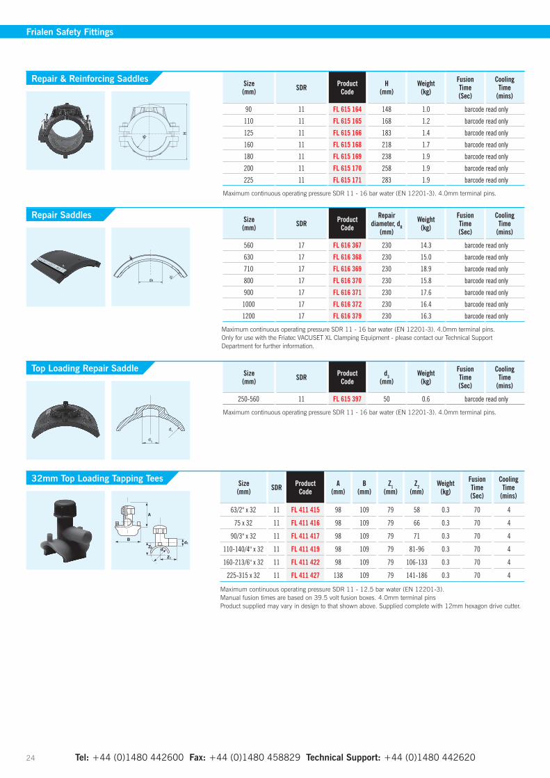
Size(mm) SDR Product
CodeA
(mm)B
(mm)Z1
(mm)Z2
(mm)Weight
(kg)
FusionTime(Sec)
CoolingTime
(mins)
63/2" x 32 11 FL 411 415 98 109 79 58 0.3 70 4
75 x 32 11 FL 411 416 98 109 79 66 0.3 70 4
90/3" x 32 11 FL 411 417 98 109 79 71 0.3 70 4
110-140/4" x 32 11 FL 411 419 98 109 79 81-96 0.3 70 4
160-213/6" x 32 11 FL 411 422 98 109 79 106-133 0.3 70 4
225-315 x 32 11 FL 411 427 138 109 79 141-186 0.3 70 4
Maximum continuous operating pressure SDR 11 - 12.5 bar water (EN 12201-3). Manual fusion times are based on 39.5 volt fusion boxes. 4.0mm terminal pins Product supplied may vary in design to that shown above. Supplied complete with 12mm hexagon drive cutter.
Size (mm) SDR Product
Coded3
(mm)Weight
(kg)
FusionTime(Sec)
CoolingTime
(mins)
250-560 11 FL 615 397 50 0.6 barcode read only
Maximum continuous operating pressure SDR 11 - 16 bar water (EN 12201-3). 4.0mm terminal pins.
Size (mm) SDR Product
CodeH
(mm)Weight
(kg)
FusionTime(Sec)
CoolingTime
(mins)
90 11 FL 615 164 148 1.0 barcode read only
110 11 FL 615 165 168 1.2 barcode read only
125 11 FL 615 166 183 1.4 barcode read only
160 11 FL 615 168 218 1.7 barcode read only
180 11 FL 615 169 238 1.9 barcode read only
200 11 FL 615 170 258 1.9 barcode read only
225 11 FL 615 171 283 1.9 barcode read only
Maximum continuous operating pressure SDR 11 - 16 bar water (EN 12201-3). 4.0mm terminal pins.
Size (mm) SDR Product
Code
Repair diameter, dR
(mm)
Weight (kg)
FusionTime(Sec)
CoolingTime
(mins)
560 17 FL 616 367 230 14.3 barcode read only
630 17 FL 616 368 230 15.0 barcode read only
710 17 FL 616 369 230 18.9 barcode read only
800 17 FL 616 370 230 15.8 barcode read only
900 17 FL 616 371 230 17.6 barcode read only
1000 17 FL 616 372 230 16.4 barcode read only
1200 17 FL 616 379 230 16.3 barcode read only
Maximum continuous operating pressure SDR 11 - 16 bar water (EN 12201-3). 4.0mm terminal pins. Only for use with the Friatec VACUSET XL Clamping Equipment - please contact our Technical Support Department for further information.
Tel: +44 (0)1480 442600 Fax: +44 (0)1480 458829 Technical Support: +44 (0)1480 442620 24
H
d1
Repair & Reinforcing Saddles
Repair Saddles
Top Loading Repair Saddle
Frialen Safety Fittings
32mm Top Loading Tapping Tees
Size(mm) SDR Product
CodeL
(mm)d3
(mm)Weight
(kg)
FusionTime(Sec)
CoolingTime
(mins)
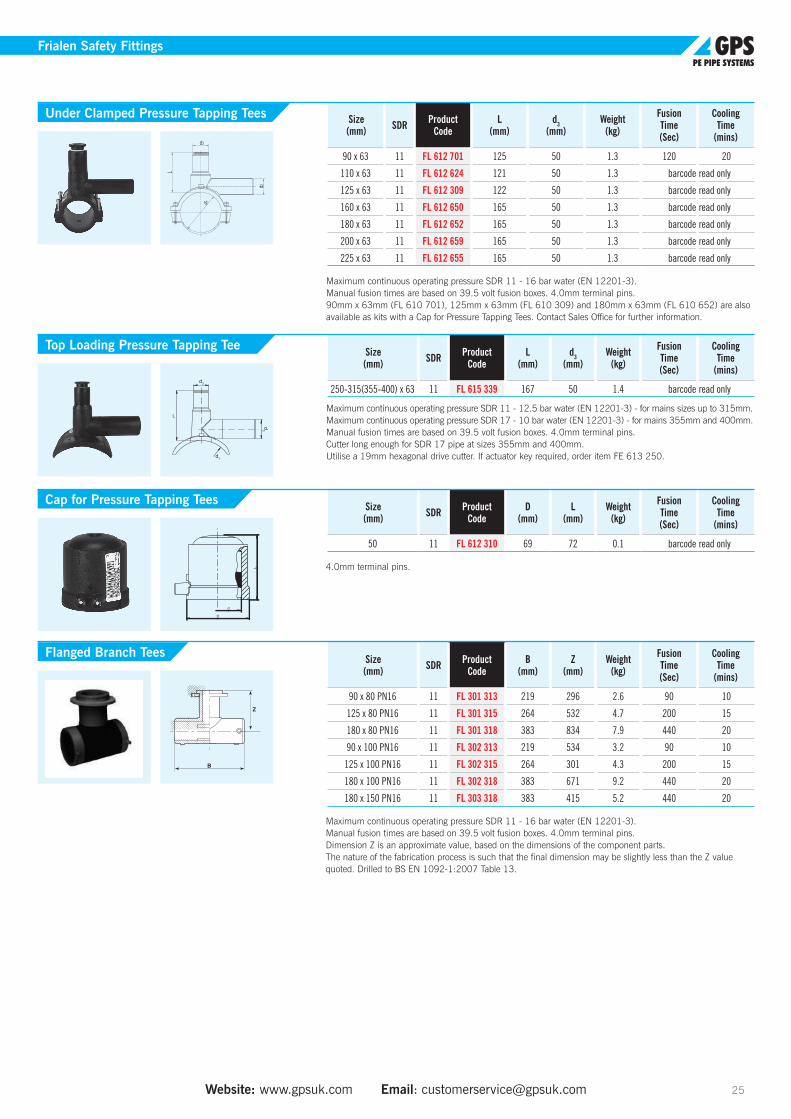
250-315(355-400) x 63 11 FL 615 339 167 50 1.4 barcode read only
Maximum continuous operating pressure SDR 11 - 12.5 bar water (EN 12201-3) - for mains sizes up to 315mm. Maximum continuous operating pressure SDR 17 - 10 bar water (EN 12201-3) - for mains 355mm and 400mm. Manual fusion times are based on 39.5 volt fusion boxes. 4.0mm terminal pins. Cutter long enough for SDR 17 pipe at sizes 355mm and 400mm. Utilise a 19mm hexagonal drive cutter. If actuator key required, order item FE 613 250.
Size(mm) SDR Product
CodeD
(mm)L
(mm)Weight
(kg)
FusionTime(Sec)
CoolingTime
(mins)
50 11 FL 612 310 69 72 0.1 barcode read only
4.0mm terminal pins.
Size(mm) SDR Product
CodeB
(mm)Z
(mm)Weight
(kg)
FusionTime(Sec)
CoolingTime
(mins)
90 x 80 PN16 11 FL 301 313 219 296 2.6 90 10
125 x 80 PN16 11 FL 301 315 264 532 4.7 200 15
180 x 80 PN16 11 FL 301 318 383 834 7.9 440 20
90 x 100 PN16 11 FL 302 313 219 534 3.2 90 10
125 x 100 PN16 11 FL 302 315 264 301 4.3 200 15
180 x 100 PN16 11 FL 302 318 383 671 9.2 440 20
180 x 150 PN16 11 FL 303 318 383 415 5.2 440 20
Maximum continuous operating pressure SDR 11 - 16 bar water (EN 12201-3).Manual fusion times are based on 39.5 volt fusion boxes. 4.0mm terminal pins. Dimension Z is an approximate value, based on the dimensions of the component parts. The nature of the fabrication process is such that the final dimension may be slightly less than the Z value quoted. Drilled to BS EN 1092-1:2007 Table 13.
Size(mm) SDR Product
CodeL
(mm)d3
(mm)Weight
(kg)
FusionTime(Sec)
CoolingTime
(mins)
90 x 63 11 FL 612 701 125 50 1.3 120 20
110 x 63 11 FL 612 624 121 50 1.3 barcode read only
125 x 63 11 FL 612 309 122 50 1.3 barcode read only
160 x 63 11 FL 612 650 165 50 1.3 barcode read only
180 x 63 11 FL 612 652 165 50 1.3 barcode read only
200 x 63 11 FL 612 659 165 50 1.3 barcode read only
225 x 63 11 FL 612 655 165 50 1.3 barcode read only
Maximum continuous operating pressure SDR 11 - 16 bar water (EN 12201-3).Manual fusion times are based on 39.5 volt fusion boxes. 4.0mm terminal pins. 90mm x 63mm (FL 610 701), 125mm x 63mm (FL 610 309) and 180mm x 63mm (FL 610 652) are also available as kits with a Cap for Pressure Tapping Tees. Contact Sales Office for further information.
Website: www.gpsuk.com Email: [email protected] 25
Frialen Safety Fittings
d2
d3
d1
L
L
Under Clamped Pressure Tapping Tees
Top Loading Pressure Tapping Tee
Cap for Pressure Tapping Tees
Flanged Branch Tees
Tel: +44 (0)1480 442600 Fax: +44 (0)1480 458829 Technical Support: +44 (0)1480 442620 26
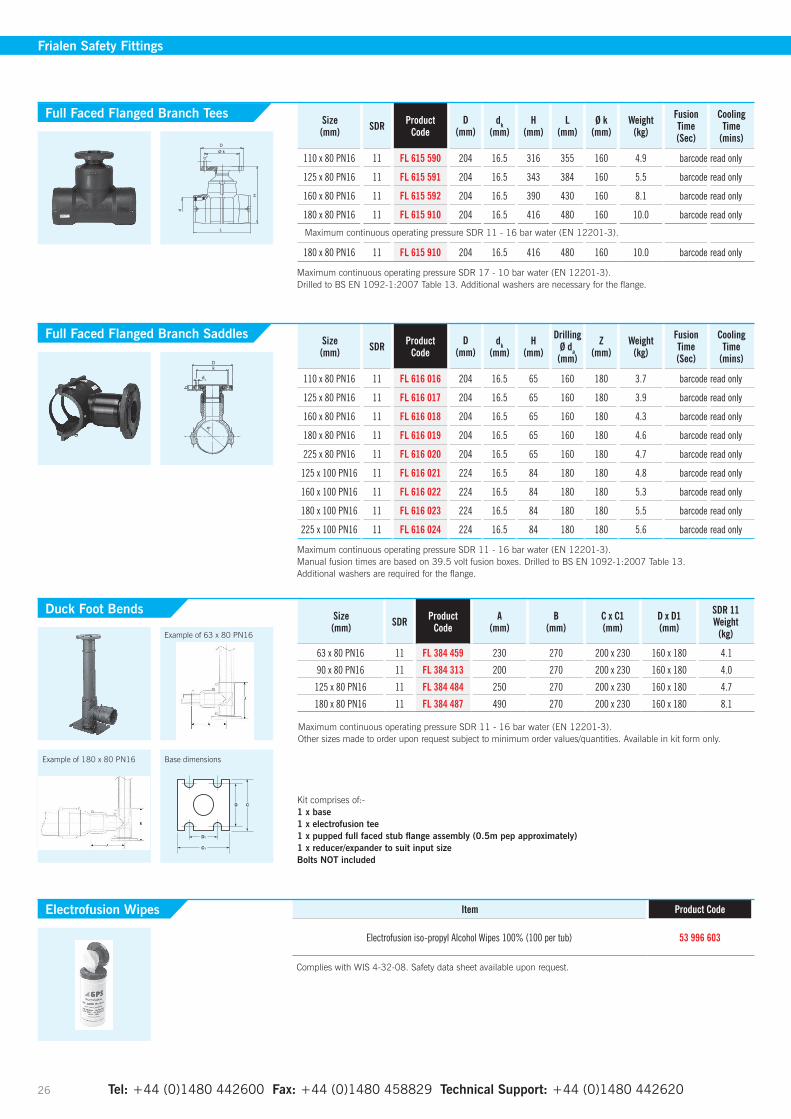
Frialen Safety Fittings
Size(mm) SDR Product
CodeD
(mm)dk
(mm)H
(mm)L
(mm)Ø k
(mm)Weight
(kg)
Fusion Time (Sec)
CoolingTime
(mins)
110 x 80 PN16 11 FL 615 590 204 16.5 316 355 160 4.9 barcode read only
125 x 80 PN16 11 FL 615 591 204 16.5 343 384 160 5.5 barcode read only
160 x 80 PN16 11 FL 615 592 204 16.5 390 430 160 8.1 barcode read only
180 x 80 PN16 11 FL 615 910 204 16.5 416 480 160 10.0 barcode read only
180 x 80 PN16 11 FL 615 910 204 16.5 416 480 160 10.0 barcode read only
Maximum continuous operating pressure SDR 17 - 10 bar water (EN 12201-3). Drilled to BS EN 1092-1:2007 Table 13. Additional washers are necessary for the flange.
Size(mm) SDR Product
CodeD
(mm)dk
(mm)H
(mm)
DrillingØ da
(mm)
Z(mm)
Weight(kg)
Fusion Time (Sec)
CoolingTime
(mins)
110 x 80 PN16 11 FL 616 016 204 16.5 65 160 180 3.7 barcode read only
125 x 80 PN16 11 FL 616 017 204 16.5 65 160 180 3.9 barcode read only
160 x 80 PN16 11 FL 616 018 204 16.5 65 160 180 4.3 barcode read only
180 x 80 PN16 11 FL 616 019 204 16.5 65 160 180 4.6 barcode read only
225 x 80 PN16 11 FL 616 020 204 16.5 65 160 180 4.7 barcode read only
125 x 100 PN16 11 FL 616 021 224 16.5 84 180 180 4.8 barcode read only
160 x 100 PN16 11 FL 616 022 224 16.5 84 180 180 5.3 barcode read only
180 x 100 PN16 11 FL 616 023 224 16.5 84 180 180 5.5 barcode read only
225 x 100 PN16 11 FL 616 024 224 16.5 84 180 180 5.6 barcode read only
Maximum continuous operating pressure SDR 11 - 16 bar water (EN 12201-3). Manual fusion times are based on 39.5 volt fusion boxes. Drilled to BS EN 1092-1:2007 Table 13. Additional washers are required for the flange.
Full Faced Flanged Branch Tees
Full Faced Flanged Branch Saddles
Maximum continuous operating pressure SDR 11 - 16 bar water (EN 12201-3).
Size(mm) SDR Product
CodeA
(mm)B
(mm)C x C1(mm)
D x D1(mm)
SDR 11Weight
(kg)
63 x 80 PN16 11 FL 384 459 230 270 200 x 230 160 x 180 4.1
90 x 80 PN16 11 FL 384 313 200 270 200 x 230 160 x 180 4.0
125 x 80 PN16 11 FL 384 484 250 270 200 x 230 160 x 180 4.7
180 x 80 PN16 11 FL 384 487 490 270 200 x 230 160 x 180 8.1
Maximum continuous operating pressure SDR 11 - 16 bar water (EN 12201-3). Other sizes made to order upon request subject to minimum order values/quantities. Available in kit form only.
Item Product Code
Electrofusion iso-propyl Alcohol Wipes 100% (100 per tub) 53 996 603
Complies with WIS 4-32-08. Safety data sheet available upon request.
Duck Foot Bends
Electrofusion Wipes
Kit comprises of:- 1 x base1 x electrofusion tee1 x pupped full faced stub flange assembly (0.5m pep approximately) 1 x reducer/expander to suit input sizeBolts NOT included
D
d3
d1
b
k
Example of 63 x 80 PN16
Example of 180 x 80 PN16 Base dimensions

Tel: +44 (0)1480 442600 Fax: +44 (0)1480 458829 Technical Support: +44 (0)1480 442620 Website: www.gpsuk.com Email: [email protected] 27
Spigot Fittings
Spigot FittingsFor Electrofusion Jointing or Butt Fusion with Narrow Clamps
Size (mm)
SDR 11 Code
SDR 17 Code
L1(mm)
L2(mm)
Z(mm)
SDR 11Weight (kg)
SDR 17Weight (kg)
32 x 25 40 441 409 - 50 45 97 0.1 -40 x 25 40 441 410 - 49 41 115 0.1 -40 x 32 40 441 413 - 50 45 117 0.1 -50 x 25 40 441 411 - 56 42 130 0.1 -50 x 32 40 441 414 - 55 47 110 0.1 -50 x 40 40 441 429 - 55 50 110 0.1 -63 x 25 40 441 395 - 64 42 137 0.1 -63 x 32 40 441 415 - 63 51 141 0.1 -63 x 40 40 441 430 - 63 55 145 0.1 -63 x 50 40 441 444 - 65 55 149 0.1 -75 x 32 40 441 416 - 74 50 150 0.2 -75 x 40 40 441 431 - 74 50 142 0.2 -75 x 50 40 441 445 - 74 55 145 0.3 -75 x 63 40 441 458 40 440 445 70 63 165 0.2 0.290 x 50 40 441 446 40 440 446 83 55 157 0.3 0.290 x 63 40 441 459 40 440 459 84 63 170 0.3 0.290 x 75 40 441 471 40 440 471 84 75 192 0.4 0.2
110 x 50 40 441 447 40 440 447 90 55 178 0.4 0.3110 x 63 40 441 460 40 440 460 94 68 207 0.5 0.3110 x 75 40 441 472 40 440 472 90 73 187 0.5 0.4110 x 90 40 441 483 40 440 483 89 83 202 0.6 0.4125 x 63 40 441 461 40 440 461 102 70 230 0.6 0.4125 x 75 40 441 473 40 440 473 90 75 188 0.7 0.4125 x 90 40 441 484 40 440 484 94 82 206 0.8 0.5
125 x 110 40 441 493 40 440 493 102 83 217 0.8 0.5140 x 90 40 441 485 40 440 485 95 84 207 0.9 0.7
140 x 110 40 441 494 40 440 494 95 90 207 0.9 0.7140 x 125 40 441 503 40 440 503 98 95 207 1.0 0.8160 x 90 40 441 486 40 440 486 108 95 248 1.1 0.9
160 x 110 40 441 495 40 440 495 102 92 250 1.3 0.9160 x 125 40 441 504 40 440 504 111 96 240 1.3 1.0160 x 140 40 441 512 40 440 512 105 95 220 1.6 1.1180 x 125 40 441 505 40 440 505 112 94 251 1.6 1.1180 x 140 40 441 513 40 440 513 100 83 218 2.0 1.3180 x 160 40 441 520 40 440 520 105 103 220 2.1 1.5200 x 140 40 441 514 40 440 514 110 100 240 2.3 2.1200 x 160 40 441 521 40 440 521 110 93 246 2.2 1.7200 x 180 40 441 527 40 440 527 140 125 277 2.6 1.8225 x 160 40 441 522 40 440 522 135 118 308 3.2 2.2225 x 180 40 441 528 40 440 528 120 118 263 3.3 2.2225 x 200 40 441 533 40 440 533 116 116 397 5.0 2.5250 x 180 40 441 529 40 440 529 130 111 303 3.7 3.1250 x 200 40 441 534 40 440 534 138 130 300 3.3 3.5250 x 225 40 441 538 40 440 538 138 135 288 4.9 3.7280 x 200 40 441 535 40 440 535 140 112 333 5.9 3.8280 x 225 40 441 539 40 440 539 140 120 335 6.1 4.1280 x 250 40 441 542 40 440 542 140 130 340 6.5 4.7315 x 225 40 441 540 40 440 540 150 120 356 7.9 5.3315 x 250 40 441 543 40 440 543 150 125 340 7.0 5.5355 x 250 40 441 544 - 165 130 390 9.1 -355 x 280 40 441 546 - 165 139 390 9.5 -355 x 315 40 441 547 - 165 150 390 9.9 -
Maximum continuous operating pressure SDR 11 - 16 bar water (EN 12201-3). Maximum continuous operating pressure SDR 17 - 10 bar water (EN 12201-3).
Reducers

Tel: +44 (0)1480 442600 Fax: +44 (0)1480 458829 Technical Support: +44 (0)1480 442620 28
Spigot Fittings
Size (mm)
SDR 11 Code
SDR 17 Code
L(mm)
B(mm)
Z(mm)
SDR 11Weight (kg)
SDR 17Weight (kg)
63 40 221 311 - 64 214 106 0.4 -75 40 222 312 - 72 246 122 0.7 -90 40 222 313 40 220 313 81 277 137 1.2 1.0
110 40 222 314 40 220 314 84 321 161 1.7 1.4125 40 222 315 40 220 315 100 345 174 2.4 2.0140 40 222 316 40 220 316 104 395 197 3.2 2.1160 40 222 317 40 220 317 104 410 206 4.5 3.0180 40 222 318 40 220 318 141 525 260 7.1 5.5200 40 222 319 40 220 319 123 501 250 8.0 6.4225 40 222 320 40 220 320 129 555 276 11.1 9.0250 40 222 321 40 220 321 132 576 288 18.7 12.2280 40 222 322 40 220 322 132 617 309 18.7 12.7315 40 222 323 40 220 323 153 695 346 37.6 20.5
Maximum continuous operating pressure SDR 11 - 16 bar water (EN 12201-3). Maximum continuous operating pressure SDR 17 - 10 bar water (EN 12201-3). Note: 250 and 315mm sizes have sections of pipe butt-fused to the moulding. On these sizes L = minimum length of pipe added.
Size (mm)
SDR 11 Code
SDR 17 Code
L(mm)
Z(mm)
SDR 11Weight (kg)
SDR 17Weight (kg)
32 40 209 308 - 70 95 0.1 -50 40 209 310 - 80 108 0.1 -63 40 209 311 - 80 117 0.1 -75 40 210 312 - 90 132 0.3 -90 40 210 313 40 208 313 91 142 0.3 0.3
110 40 210 314 40 208 314 99 162 0.6 0.6125 40 210 315 40 208 315 103 169 1.1 0.8140 40 210 316 40 208 316 120 200 1.5 1.0160 40 210 317 40 208 317 142 233 1.9 1.4180 40 210 318 40 208 318 142 247 2.9 2.3200 40 210 319 40 208 319 153 262 3.6 2.5225 40 210 320 40 208 320 154 281 5.0 3.8250 40 210 321 40 208 321 134 293 6.4 5.0280 40 210 322 40 208 322 144 330 11.5 8.0315 40 210 323 40 208 323 154 370 15.7 9.0
Maximum continuous operating pressure SDR 11 - 16 bar water (EN 12201-3). Maximum continuous operating pressure SDR 17 - 10 bar water (EN 12201-3). Note: 250 and 315mm sizes have sections of pipe butt-fused to the moulding. On these sizes L = minimum length of pipe added.
Size (mm)
SDR 11 Code
SDR 17 Code
L(mm)
Z(mm)
SDR 11Weight (kg)
SDR 17Weight (kg)
32 40 215 308 - 71 90 0.1 -50 40 215 310 - 62 76 0.1 -63 40 215 311 - 66 88 0.1 -75 40 216 312 - 71 90 0.2 -90 40 216 313 40 214 313 83 105 0.5 0.3
110 40 216 314 40 214 314 93 121 0.9 0.6125 40 216 315 40 214 315 99 137 1.2 0.9140 40 216 316 40 214 316 121 168 1.6 1.1160 40 216 317 40 214 317 142 190 2.3 1.6180 40 216 318 40 214 318 141 196 2.6 2.0200 40 216 319 40 214 319 153 207 3.7 2.4225 40 216 320 40 214 320 154 210 5.1 4.1250 40 216 321 40 214 321 133 220 9.7 6.3280 40 216 322 40 214 322 144 227 10.6 8.1315 40 216 323 40 214 323 155 250 16.5 12.5
Maximum continuous operating pressure SDR 11 - 16 bar water (EN 12201-3). Maximum continuous operating pressure SDR 17 - 10 bar water (EN 12201-3). Note: 250 and 315mm sizes have sections of pipe butt-fused to the moulding. On these sizes L = minimum length of pipe added.
90º Equal Tees
90º Elbows
45º Elbows
Website: www.gpsuk.com Email: [email protected] 29
Spigot Fittings
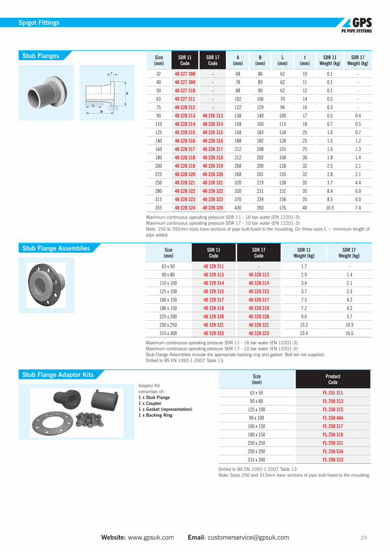
Size (mm)
SDR 11 Code
SDR 17 Code
A(mm)
B(mm)
L(mm)
t(mm)
SDR 11Weight (kg)
SDR 17Weight (kg)
32 40 227 308 - 68 86 62 10 0.1 -
40 40 227 309 - 78 89 62 11 0.1 -
50 40 227 310 - 88 90 62 12 0.1 -
63 40 227 311 - 102 106 70 14 0.2 -
75 40 228 312 - 122 129 94 16 0.3 -
90 40 228 313 40 226 313 138 140 100 17 0.5 0.4
110 40 228 314 40 226 314 158 160 113 18 0.7 0.5
125 40 228 315 40 226 315 158 183 134 25 1.0 0.7
140 40 228 316 40 226 316 188 182 128 25 1.5 1.2
160 40 228 317 40 226 317 212 208 155 25 1.6 1.3
180 40 228 318 40 226 318 212 202 168 30 1.8 1.4
200 40 228 319 40 226 319 268 200 128 32 2.5 2.1
225 40 228 320 40 226 320 268 201 135 32 2.8 2.1
250 40 228 321 40 226 321 320 219 138 35 3.7 4.4
280 40 228 322 40 226 322 320 231 152 35 8.4 6.0
315 40 228 323 40 226 323 370 239 158 35 8.5 6.0
355 40 228 324 40 226 324 430 260 176 40 10.5 7.4
Maximum continuous operating pressure SDR 11 - 16 bar water (EN 12201-3). Maximum continuous operating pressure SDR 17 - 10 bar water (EN 12201-3). Note: 250 to 355mm sizes have sections of pipe butt-fused to the moulding. On these sizes L = minimum length of pipe added.
Size (mm)
SDR 11 Code
SDR 17 Code
SDR 11Weight (kg)
SDR 17Weight (kg)
63 x 50 40 329 311 - 1.7 -
90 x 80 40 329 313 40 328 313 2.9 1.4
110 x 100 40 329 314 40 328 314 3.4 2.1
125 x 100 40 329 315 40 328 315 3.7 2.3
160 x 150 40 329 317 40 328 317 7.3 4.2
180 x 150 40 329 318 40 328 318 7.2 4.2
225 x 200 40 329 320 40 328 320 9.6 5.7
250 x 250 40 329 321 40 328 321 15.2 10.9
315 x 300 40 329 323 40 328 323 23.4 16.6
Maximum continuous operating pressure SDR 11 - 16 bar water (EN 12201-3). Maximum continuous operating pressure SDR 17 - 10 bar water (EN 12201-3) Stub Flange Assemblies include the appropriate backing ring and gasket. Bolt set not supplied. Drilled to BS EN 1092-1:2007 Table 13.
Stub Flanges
Stub Flange Assemblies
Size (mm)
Product Code
63 x 50 FL 251 311
90 x 80 FL 250 313
125 x 100 FL 250 315
90 x 100 FL 250 484
160 x 150 FL 250 317
180 x 150 FL 250 318
250 x 250 FL 250 321
250 x 200 FL 250 534
315 x 300 FL 250 323
Drilled to BS EN 1092-1:2007 Table 13. Note: Sizes 250 and 315mm have sections of pipe butt-fused to the moulding.
Stub Flange Adaptor Kits
Adaptor Kit comprises of:- 1 x Stub Flange 1 x Coupler1 x Gasket (representation) 1 x Backing Ring
Tel: +44 (0)1480 442600 Fax: +44 (0)1480 458829 Technical Support: +44 (0)1480 442620 30
Spigot Fittings
Size (mm)
SDR 11 Code
SDR 17 Code
B(mm)
L(mm)
SDR 11Weight (kg)
SDR 17Weight (kg)
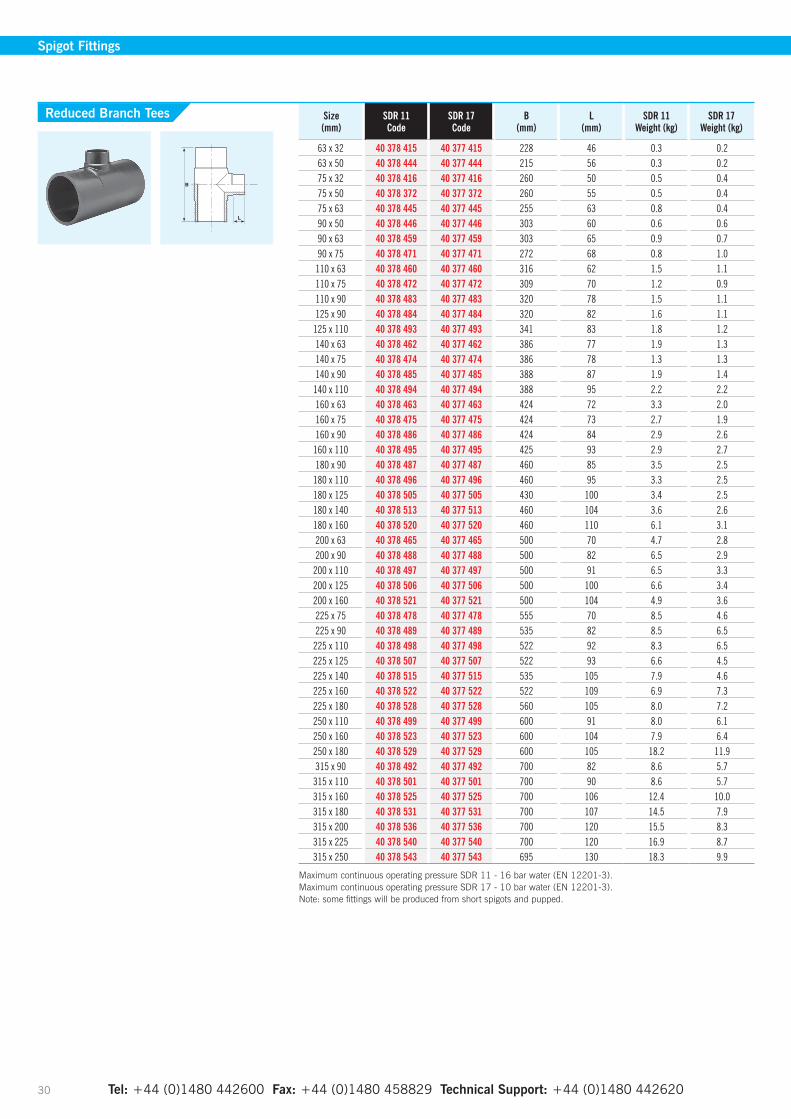
63 x 32 40 378 415 40 377 415 228 46 0.3 0.263 x 50 40 378 444 40 377 444 215 56 0.3 0.275 x 32 40 378 416 40 377 416 260 50 0.5 0.475 x 50 40 378 372 40 377 372 260 55 0.5 0.475 x 63 40 378 445 40 377 445 255 63 0.8 0.490 x 50 40 378 446 40 377 446 303 60 0.6 0.690 x 63 40 378 459 40 377 459 303 65 0.9 0.790 x 75 40 378 471 40 377 471 272 68 0.8 1.0
110 x 63 40 378 460 40 377 460 316 62 1.5 1.1110 x 75 40 378 472 40 377 472 309 70 1.2 0.9110 x 90 40 378 483 40 377 483 320 78 1.5 1.1125 x 90 40 378 484 40 377 484 320 82 1.6 1.1
125 x 110 40 378 493 40 377 493 341 83 1.8 1.2140 x 63 40 378 462 40 377 462 386 77 1.9 1.3140 x 75 40 378 474 40 377 474 386 78 1.3 1.3140 x 90 40 378 485 40 377 485 388 87 1.9 1.4
140 x 110 40 378 494 40 377 494 388 95 2.2 2.2160 x 63 40 378 463 40 377 463 424 72 3.3 2.0160 x 75 40 378 475 40 377 475 424 73 2.7 1.9160 x 90 40 378 486 40 377 486 424 84 2.9 2.6
160 x 110 40 378 495 40 377 495 425 93 2.9 2.7180 x 90 40 378 487 40 377 487 460 85 3.5 2.5
180 x 110 40 378 496 40 377 496 460 95 3.3 2.5180 x 125 40 378 505 40 377 505 430 100 3.4 2.5180 x 140 40 378 513 40 377 513 460 104 3.6 2.6180 x 160 40 378 520 40 377 520 460 110 6.1 3.1200 x 63 40 378 465 40 377 465 500 70 4.7 2.8200 x 90 40 378 488 40 377 488 500 82 6.5 2.9
200 x 110 40 378 497 40 377 497 500 91 6.5 3.3200 x 125 40 378 506 40 377 506 500 100 6.6 3.4200 x 160 40 378 521 40 377 521 500 104 4.9 3.6225 x 75 40 378 478 40 377 478 555 70 8.5 4.6225 x 90 40 378 489 40 377 489 535 82 8.5 6.5
225 x 110 40 378 498 40 377 498 522 92 8.3 6.5225 x 125 40 378 507 40 377 507 522 93 6.6 4.5225 x 140 40 378 515 40 377 515 535 105 7.9 4.6225 x 160 40 378 522 40 377 522 522 109 6.9 7.3225 x 180 40 378 528 40 377 528 560 105 8.0 7.2250 x 110 40 378 499 40 377 499 600 91 8.0 6.1250 x 160 40 378 523 40 377 523 600 104 7.9 6.4250 x 180 40 378 529 40 377 529 600 105 18.2 11.9315 x 90 40 378 492 40 377 492 700 82 8.6 5.7
315 x 110 40 378 501 40 377 501 700 90 8.6 5.7315 x 160 40 378 525 40 377 525 700 106 12.4 10.0315 x 180 40 378 531 40 377 531 700 107 14.5 7.9315 x 200 40 378 536 40 377 536 700 120 15.5 8.3315 x 225 40 378 540 40 377 540 700 120 16.9 8.7315 x 250 40 378 543 40 377 543 695 130 18.3 9.9
Maximum continuous operating pressure SDR 11 - 16 bar water (EN 12201-3). Maximum continuous operating pressure SDR 17 - 10 bar water (EN 12201-3). Note: some fittings will be produced from short spigots and pupped.
Reduced Branch Tees
Tel: +44 (0)1480 442600 Fax: +44 (0)1480 458829 Technical Support: +44 (0)1480 442620 Website: www.gpsuk.com Email: [email protected] 31
Spigot Fittings
Size (mm)
SDR 11 Code
SDR 17 Code
Z(mm)
SDR 11Weight (kg)
SDR 17Weight (kg)
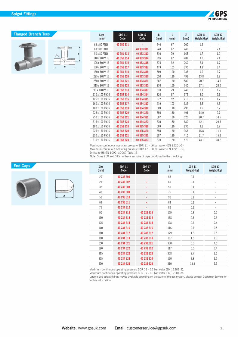
20 40 233 306 - 58 0.1 -
25 40 233 307 - 65 0.1 -
32 40 233 308 - 55 0.1 -
40 40 233 309 - 76 0.1 -
50 40 233 310 - 90 0.1 -
63 40 233 311 - 84 0.1 -
75 40 234 312 - 86 0.2 -
90 40 234 313 40 232 313 109 0.3 0.2
110 40 234 314 40 232 314 138 0.3 0.3
125 40 234 315 40 232 315 128 0.6 0.4
140 40 234 316 40 232 316 116 0.7 0.5
160 40 234 317 40 232 317 179 1.3 0.8
180 40 234 318 40 232 318 167 1.5 1.0
250 40 234 321 40 232 321 330 5.0 4.5
280 40 234 322 40 232 322 117 5.0 3.4
315 40 234 323 40 232 323 358 8.7 6.5
355 40 234 324 40 232 324 120 9.8 6.5
400 40 234 325 40 232 325 310 13.4 9.3
Maximum continuous operating pressure SDR 11 - 16 bar water (EN 12201-3). Maximum continuous operating pressure SDR 17 - 10 bar water (EN 12201-3). Larger sized spigot fittings maybe available epending on pressure of the gas system, please contact Customer Service for further information.
End Caps
Size (mm)
SDR 11 Code
SDR 17 Code
B(mm)
L(mm)
Z(mm)
SDR 11Weight (kg)
SDR 17Weight (kg)
63 x 50 PN16 40 350 311 - 240 67 200 1.5 -63 x 80 PN16 - 40 363 311 240 67 240 - 2.490 x 80 PN16 40 351 313 40 363 313 310 79 165 1.7 1.2
110 x 80 PN16 40 351 314 40 363 314 326 87 289 3.0 2.1125 x 80 PN16 40 351 315 40 363 315 375 92 260 2.4 1.7160 x 80 PN16 40 351 317 40 363 317 419 103 330 4.9 3.4180 x 80 PN16 40 351 318 40 363 318 509 120 335 9.6 6.7225 x 80 PN16 40 351 320 40 363 320 550 130 492 13.8 9.7250 x 80 PN16 40 351 321 40 363 321 687 130 580 20.7 14.5315 x 80 PN16 40 351 323 40 363 323 870 150 740 37.1 26.090 x 100 PN16 40 352 313 40 364 313 310 79 240 1.7 1.2
110 x 100 PN16 40 352 314 40 364 314 326 87 175 3.0 2.1125 x 100 PN16 40 352 315 40 364 315 372 92 215 3.9 1.7160 x 100 PN16 40 352 317 40 364 317 419 103 332 6.5 4.6180 x 100 PN16 40 352 318 40 364 318 509 110 290 9.6 6.7225 x 100 PN16 40 352 320 40 364 320 550 130 494 14.0 9.7250 x 100 PN16 40 352 321 40 364 321 687 130 520 20.7 14.5315 x 100 PN16 40 352 323 40 364 323 830 150 680 42.1 29.5180 x 150 PN16 40 353 318 40 365 318 509 110 230 9.6 6.7225 x 150 PN16 40 353 320 40 365 320 550 130 363 15.8 11.1250 x 150 PN16 40 353 321 40 365 321 687 130 410 21.7 15.2315 x 150 PN16 40 353 323 40 365 323 870 150 570 43.1 30.2
Maximum continuous operating pressure SDR 11 - 16 bar water (EN 12201-3). Maximum continuous operating pressure SDR 17 - 10 bar water (EN 12201-3). Drilled to BS EN 1092-1:2007 Table 13. Note: Sizes 250 and 315mm have sections of pipe butt-fused to the moulding.
Flanged Branch Tees
Size (mm)
SDR 11 Code
SDR 17 Code
Min L(mm)
Min L1(mm) R/D SDR 11
Weight (kg)SDR 17
Weight (kg)
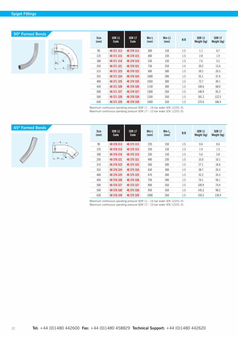
90 40 376 313 40 375 313 220 150 1.5 0.6 0.6
125 40 376 315 40 375 315 250 150 1.5 1.9 1.3
180 40 376 318 40 375 318 350 150 1.5 5.6 3.8
250 40 376 321 40 375 321 490 250 1.5 15.0 10.1
315 40 376 323 40 375 323 560 300 1.5 27.1 18.4
355 40 376 324 40 375 324 630 300 1.5 38.7 26.3
400 40 376 325 40 375 325 670 300 1.5 52.2 35.3
450 40 376 326 40 375 326 750 300 1.5 74.1 50.1
500 40 376 327 40 375 327 900 350 1.5 109.9 74.4
560 40 376 328 40 375 328 950 350 1.5 145.2 98.2
630 40 376 329 40 375 329 1000 350 1.5 193.5 130.9
Maximum continuous operating pressure SDR 11 - 16 bar water (EN 12201-3). Maximum continuous operating pressure SDR 17 - 10 bar water (EN 12201-3).
Tel: +44 (0)1480 442600 Fax: +44 (0)1480 458829 Technical Support: +44 (0)1480 442620 32
Spigot Fittings
45º Formed Bends
Size (mm)
SDR 11 Code
SDR 17 Code
Min L(mm)
Min L1(mm) R/D SDR 11
Weight (kg)SDR 17
Weight (kg)
90 40 371 313 40 370 313 300 150 1.5 1.1 0.7
125 40 371 315 40 370 315 400 150 1.5 2.8 1.9
180 40 371 318 40 370 318 530 150 1.5 7.6 5.2
250 40 371 321 40 370 321 730 250 1.5 20.2 13.6
315 40 371 323 40 370 323 900 300 1.5 39.2 26.5
355 40 371 324 40 370 324 1000 300 1.5 55.1 37.4
400 40 371 325 40 370 325 1050 300 1.5 72.7 49.1
450 40 371 326 40 370 326 1150 300 1.5 100.6 68.0
500 40 371 327 40 370 327 1300 350 1.5 140.9 95.3
560 40 371 328 40 370 328 1350 350 1.5 181.2 122.5
630 40 371 329 40 370 329 1600 350 1.5 275.6 186.4
Maximum continuous operating pressure SDR 11 - 16 bar water (EN 12201-3). Maximum continuous operating pressure SDR 17 - 10 bar water (EN 12201-3).
90º Formed Bends
Size (mm)
SDR 11 Code
SDR 17 Code
Min L(mm)
Min L1(mm) R/D SDR 11
Weight (kg)SDR 17
Weight (kg)
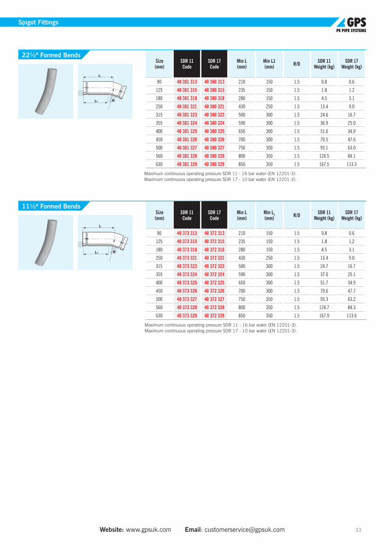
90 40 373 313 40 372 313 210 150 1.5 0.8 0.6
125 40 373 315 40 372 315 235 150 1.5 1.8 1.2
180 40 373 318 40 372 318 280 150 1.5 4.5 3.1
250 40 373 321 40 372 321 430 250 1.5 13.4 9.0
315 40 373 323 40 372 323 500 300 1.5 24.7 16.7
355 40 373 324 40 372 324 590 300 1.5 37.0 25.1
400 40 373 325 40 372 325 650 300 1.5 51.7 34.9
450 40 373 326 40 372 326 700 300 1.5 70.6 47.7
500 40 373 327 40 372 327 750 350 1.5 93.3 63.2
560 40 373 328 40 372 328 800 350 1.5 124.7 84.3
630 40 373 329 40 372 329 850 350 1.5 167.9 113.6
Maximum continuous operating pressure SDR 11 - 16 bar water (EN 12201-3). Maximum continuous operating pressure SDR 17 - 10 bar water (EN 12201-3).
Size (mm)
SDR 11 Code
SDR 17 Code
Min L(mm)
Min L1(mm) R/D SDR 11
Weight (kg)SDR 17
Weight (kg)
90 40 381 313 40 380 313 210 150 1.5 0.8 0.6
125 40 381 315 40 380 315 235 150 1.5 1.8 1.2
180 40 381 318 40 380 318 280 150 1.5 4.5 3.1
250 40 381 321 40 380 321 430 250 1.5 13.4 9.0
315 40 381 323 40 380 323 500 300 1.5 24.6 16.7
355 40 381 324 40 380 324 590 300 1.5 36.9 25.0
400 40 381 325 40 380 325 650 300 1.5 51.6 34.9
450 40 381 326 40 380 326 700 300 1.5 70.5 47.6
500 40 381 327 40 380 327 750 350 1.5 93.1 63.0
560 40 381 328 40 380 328 800 350 1.5 124.5 84.1
630 40 381 329 40 380 329 850 350 1.5 167.5 113.3
Maximum continuous operating pressure SDR 11 - 16 bar water (EN 12201-3). Maximum continuous operating pressure SDR 17 - 10 bar water (EN 12201-3).
Website: www.gpsuk.com Email: [email protected] 33
Spigot Fittings
22½º Formed Bends
11½º Formed Bends

Pupped FittingsElongated Spigot Fittings For Butt Fusion Or Electrofusion Jointing
Size (mm)
SDR 11 Code
SDR 17Code
B(mm)
L(mm)
SDR 11Weight (kg)
SDR 17Weight (kg)
90 x 63 41 323 459 41 322 459 1160 500 1.9 1.3
110 x 90 41 323 483 41 322 483 1190 500 3.1 2.1
125 x 63 41 323 461 41 322 461 1220 500 3.2 2.2
125 x 90 41 323 484 41 322 484 1200 500 3.8 2.6
160 x 90 41 323 486 41 322 486 1240 500 5.5 3.9
160 x 110 41 323 495 41 322 495 1240 500 6.2 4.2
160 x 125 41 323 504 41 322 504 1230 500 6.7 4.6
180 x 90 41 323 487 41 322 487 1440 500 6.1 4.2
180 x 125 41 323 505 41 322 505 1240 500 7.9 5.4
200 x 160 41 323 506 41 322 506 1235 500 10.8 7.4
225 x 160 41 323 507 41 322 507 1298 500 13.0 8.9
250 x 125 41 323 508 41 322 508 1530 500 13.5 9.3
250 x 180 41 323 529 41 322 529 1290 500 16.0 11.5
315 x 250 41 323 543 41 322 543 1330 500 28.0 20.0
315 x 280 41 323 545 41 322 545 1222 500 28.2 19.1
355 x 125 41 323 571 41 322 571 1563 500 25.9 19.2
355 x 180 41 323 532 41 322 532 1420 500 27.2 19.9
355 x 225 41 323 541 41 322 541 1245 500 27.4 20.2
355 x 250 41 323 544 41 322 544 1245 500 28.6 20.9
355 x 280 41 323 546 41 322 546 1245 500 30.3 21.9
355 x 315 41 323 547 41 322 547 1245 500 32.6 23.4
400 x 180 41 323 560 41 322 560 1435 500 33.6 22.8
400 x 250 41 323 563 41 322 563 1260 500 35.0 23.8
400 x 280 41 323 564 41 322 564 1260 500 36.7 25.1
400 x 315 41 323 565 41 322 565 1260 500 38.5 26.1
400 x 355 41 323 566 41 322 566 1260 500 41.5 28.2
450 x 250 41 323 573 41 322 573 2460 1000 81.2 55.0
450 x 280 41 323 584 41 322 584 2230 1000 80.9 55.0
450 x 315 41 323 574 41 322 574 2230 1000 85.3 57.8
450 x 355 41 323 575 41 322 575 2230 1000 91.6 62.1
450 x 400 41 323 576 41 322 576 2230 1000 99.5 67.3
500 x 355 41 323 579 41 322 579 2230 1000 107.1 72.7
500 x 400 41 323 580 41 322 580 2230 1000 115.0 78.3
500 x 450 41 323 581 41 322 581 2200 1000 124.2 84.0
560 x 450 41 323 586 41 322 586 2200 1000 145.0 98.1
560 x 500 41 323 594 41 322 594 2200 1000 155.6 105.4
630 x 500 41 323 599 41 322 599 2200 1000 183.4 124.3
630 x 560 41 323 595 41 322 595 2200 1000 196.6 133.1
710 x 630 41 323 597 41 322 597 2230 1000 tbc 170.1
Reducers
Dimensions of pupped fittings should be used subject to a +/– 5mm tolerance due to the nature of the fabrication process. Standard pup leg lengths: 0.5m in sizes up to 400mm; 1.0m in sizes 450mm to 1200mm.
Additional bespoke large diameter fabricated fittings are available to order - please contact our Sales Office for further information.
Tel: +44 (0)1480 442600 Fax: +44 (0)1480 458829 Technical Support: +44 (0)1480 442620 34
Pupped Fittings

Size (mm)
SDR 11 Code
SDR 17Code
L(mm)
Z(mm)
SDR 11Weight (kg)
SDR 17Weight (kg)
90 41 309 313 41 308 313 500 629 2.6 1.9
110 41 309 314 41 308 314 500 670 4.3 2.9
125 41 309 315 41 308 315 500 660 5.4 3.8
160 41 309 317 41 308 317 500 720 9.2 6.5
180 41 309 318 41 308 318 500 720 12.1 8.2
200 41 309 319 41 308 319 500 741 15.4 10.5
225 41 309 320 41 308 320 500 768 19.4 14.0
250 41 309 321 41 308 321 500 900 22.4 15.6
280 41 309 322 41 308 322 500 840 30.3 20.2
315 41 309 323 41 308 323 500 920 39.2 25.9
355 41 309 324 41 308 324 500 880 53.5 35.0
Size (mm)
SDR 11 Code
SDR 17Code
L(mm)
Z(mm)
SDR 11Weight (kg)
SDR 17Weight (kg)
90 41 315 313 41 314 313 500 595 2.5 1.7
110 41 315 314 41 314 314 500 607 3.9 2.7
125 41 315 315 41 314 315 500 616 5.1 3.7
160 41 315 317 41 314 317 500 635 8.6 6.0
180 41 315 318 41 314 318 500 660 11.1 7.7
200 41 315 319 41 314 319 500 672 13.8 9.3
225 41 315 320 41 314 320 500 685 17.8 12.1
250 41 315 321 41 314 321 500 750 24.3 16.8
280 41 315 322 41 314 322 500 750 31.6 22.1
315 41 315 323 41 314 323 500 795 39.1 28.2
355 41 315 324 41 314 324 500 620 105.1 69.6
90º Elbows
45º Elbows
Dimensions of pupped fittings should be used subject to a +/– 5mm tolerance due to the nature of the fabrication process. Standard pup leg lengths: 0.5m in sizes up to 400mm; 1.0m in sizes 450mm to 1200mm.
Additional bespoke large diameter fabricated fittings are available to order - please contact our Sales Office for further information.
Tel: +44 (0)1480 442600 Fax: +44 (0)1480 458829 Technical Support: +44 (0)1480 442620 Website: www.gpsuk.com Email: [email protected] 35
Pupped Fittings
Size (mm)
SDR 11 Code
SDR 17Code
L(mm)
B(mm)
Z(mm)
SDR 11Weight (kg)
SDR 17Weight (kg)
90 41 321 313 41 320 313 500 1310 656 4.1 3.0
110 41 321 314 41 320 314 500 1326 670 6.4 4.6
125 41 321 315 41 320 315 500 1372 687 8.4 6.2
160 41 321 317 41 320 317 500 1419 708 14.1 9.8
180 41 321 318 41 320 318 500 1509 765 19.0 13.6
200 41 321 319 41 320 319 500 1500 750 24.2 17.0
225 41 321 320 41 320 320 500 1550 775 30.7 22.5
250 41 321 321 41 320 321 500 1540 840 34.7 24.2
280 41 321 322 41 320 322 500 1680 840 47.8 31.8
315 41 321 323 41 320 323 500 1820 910 60.2 40.6
355 41 321 324 41 320 324 500 1690 845 81.1 54.9
400 41 321 325 41 320 325 500 1722 860 101.6 69.7
Equal Tees
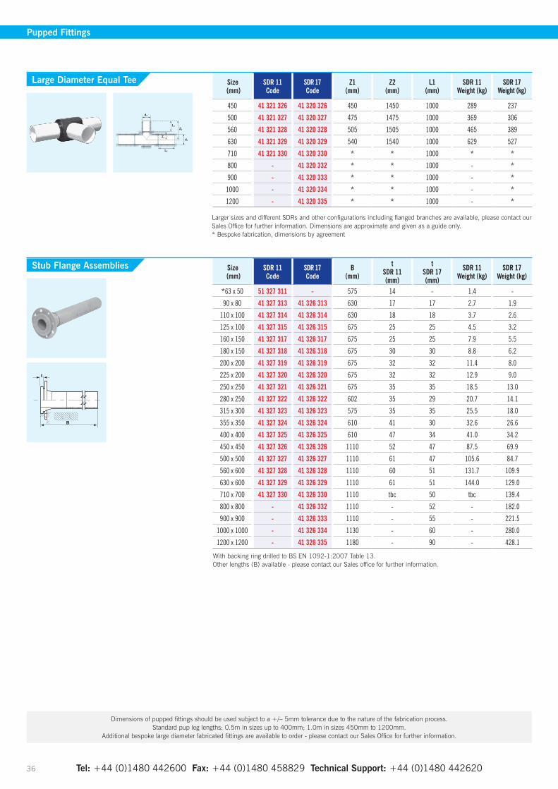
Size (mm)
SDR 11Code
SDR 17Code
B(mm)
tSDR 11(mm)
tSDR 17(mm)
SDR 11Weight (kg)
SDR 17Weight (kg)
*63 x 50 51 327 311 - 575 14 - 1.4 -
90 x 80 41 327 313 41 326 313 630 17 17 2.7 1.9
110 x 100 41 327 314 41 326 314 630 18 18 3.7 2.6
125 x 100 41 327 315 41 326 315 675 25 25 4.5 3.2
160 x 150 41 327 317 41 326 317 675 25 25 7.9 5.5
180 x 150 41 327 318 41 326 318 675 30 30 8.8 6.2
200 x 200 41 327 319 41 326 319 675 32 32 11.4 8.0
225 x 200 41 327 320 41 326 320 675 32 32 12.9 9.0
250 x 250 41 327 321 41 326 321 675 35 35 18.5 13.0
280 x 250 41 327 322 41 326 322 602 35 29 20.7 14.1
315 x 300 41 327 323 41 326 323 575 35 35 25.5 18.0
355 x 350 41 327 324 41 326 324 610 41 30 32.6 26.6
400 x 400 41 327 325 41 326 325 610 47 34 41.0 34.2
450 x 450 41 327 326 41 326 326 1110 52 47 87.5 69.9
500 x 500 41 327 327 41 326 327 1110 61 47 105.6 84.7
560 x 600 41 327 328 41 326 328 1110 60 51 131.7 109.9
630 x 600 41 327 329 41 326 329 1110 61 51 144.0 129.0
710 x 700 41 327 330 41 326 330 1110 tbc 50 tbc 139.4
800 x 800 - 41 326 332 1110 - 52 - 182.0
900 x 900 - 41 326 333 1110 - 55 - 221.5
1000 x 1000 - 41 326 334 1130 - 60 - 280.0
1200 x 1200 - 41 326 335 1180 - 90 - 428.1
With backing ring drilled to BS EN 1092-1:2007 Table 13. Other lengths (B) available - please contact our Sales office for further information.
Tel: +44 (0)1480 442600 Fax: +44 (0)1480 458829 Technical Support: +44 (0)1480 442620 36
Size (mm)
SDR 11Code
SDR 17Code
Z1(mm)
Z2(mm)
L1(mm)
SDR 11Weight (kg)
SDR 17Weight (kg)
450 41 321 326 41 320 326 450 1450 1000 289 237
500 41 321 327 41 320 327 475 1475 1000 369 306
560 41 321 328 41 320 328 505 1505 1000 465 389
630 41 321 329 41 320 329 540 1540 1000 629 527
710 41 321 330 41 320 330 * * 1000 * *
800 - 41 320 332 * * 1000 - *
900 - 41 320 333 * * 1000 - *
1000 - 41 320 334 * * 1000 - *
1200 - 41 320 335 * * 1000 - *
Larger sizes and different SDRs and other configurations including flanged branches are available, please contact our Sales Office for further information. Dimensions are approximate and given as a guide only. * Bespoke fabrication, dimensions by agreement
Stub Flange Assemblies
Large Diameter Equal Tee
Dimensions of pupped fittings should be used subject to a +/– 5mm tolerance due to the nature of the fabrication process. Standard pup leg lengths: 0.5m in sizes up to 400mm; 1.0m in sizes 450mm to 1200mm.
Additional bespoke large diameter fabricated fittings are available to order - please contact our Sales Office for further information.
Pupped Fittings
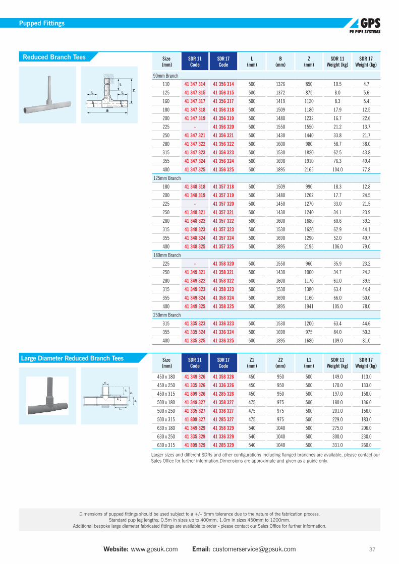
Website: www.gpsuk.com Email: [email protected] 37
Dimensions of pupped fittings should be used subject to a +/– 5mm tolerance due to the nature of the fabrication process. Standard pup leg lengths: 0.5m in sizes up to 400mm; 1.0m in sizes 450mm to 1200mm.
Additional bespoke large diameter fabricated fittings are available to order - please contact our Sales Office for further information.
Pupped Fittings
Size (mm)
SDR 11Code
SDR 17Code
L(mm)
B(mm)
Z(mm)
SDR 11Weight (kg)
SDR 17Weight (kg)
90mm Branch
110 41 347 314 41 356 314 500 1326 850 10.5 4.7
125 41 347 315 41 356 315 500 1372 875 8.0 5.6
160 41 347 317 41 356 317 500 1419 1120 8.3 5.4
180 41 347 318 41 356 318 500 1509 1180 17.9 12.5
200 41 347 319 41 356 319 500 1480 1232 16.7 22.6
225 - 41 356 320 500 1550 1550 21.2 13.7
250 41 347 321 41 356 321 500 1430 1440 33.8 21.7
280 41 347 322 41 356 322 500 1600 980 58.7 38.0
315 41 347 323 41 356 323 500 1530 1820 62.5 43.8
355 41 347 324 41 356 324 500 1690 1910 76.3 49.4
400 41 347 325 41 356 325 500 1895 2165 104.0 77.8
125mm Branch
180 41 348 318 41 357 318 500 1509 990 18.3 12.8
200 41 348 319 41 357 319 500 1480 1262 17.7 24.5
225 - 41 357 320 500 1450 1270 33.0 21.5
250 41 348 321 41 357 321 500 1430 1240 34.1 23.9
280 41 348 322 41 357 322 500 1600 1680 60.6 39.2
315 41 348 323 41 357 323 500 1530 1620 62.9 44.1
355 41 348 324 41 357 324 500 1690 1290 52.0 49.7
400 41 348 325 41 357 325 500 1895 2195 106.0 79.0
180mm Branch
225 - 41 358 320 500 1550 960 35.9 23.2
250 41 349 321 41 358 321 500 1430 1000 34.7 24.2
280 41 349 322 41 358 322 500 1600 1170 61.0 39.5
315 41 349 323 41 358 323 500 1530 1380 63.4 44.4
355 41 349 324 41 358 324 500 1690 1160 66.0 50.0
400 41 349 325 41 358 325 500 1895 1941 105.0 78.0
250mm Branch
315 41 335 323 41 336 323 500 1530 1200 63.4 44.6
355 41 335 324 41 336 324 500 1690 975 84.0 50.3
400 41 335 325 41 336 325 500 1895 1680 109.0 81.0
Size (mm)
SDR 11Code
SDR 17Code
Z1(mm)
Z2(mm)
L1(mm)
SDR 11Weight (kg)
SDR 17Weight (kg)
450 x 180 41 349 326 41 358 326 450 950 500 149.0 113.0
450 x 250 41 335 326 41 336 326 450 950 500 170.0 133.0
450 x 315 41 809 326 41 285 326 450 950 500 197.0 158.0
500 x 180 41 349 327 41 358 327 475 975 500 180.0 136.0
500 x 250 41 335 327 41 336 327 475 975 500 201.0 156.0
500 x 315 41 809 327 41 285 327 475 975 500 229.0 183.0
630 x 180 41 349 329 41 358 329 540 1040 500 275.0 206.0
630 x 250 41 335 329 41 336 329 540 1040 500 300.0 230.0
630 x 315 41 809 329 41 285 329 540 1040 500 331.0 260.0
Larger sizes and different SDRs and other configurations including flanged branches are available, please contact our Sales Office for further information.Dimensions are approximate and given as a guide only.
Reduced Branch Tees
Large Diameter Reduced Branch Tees
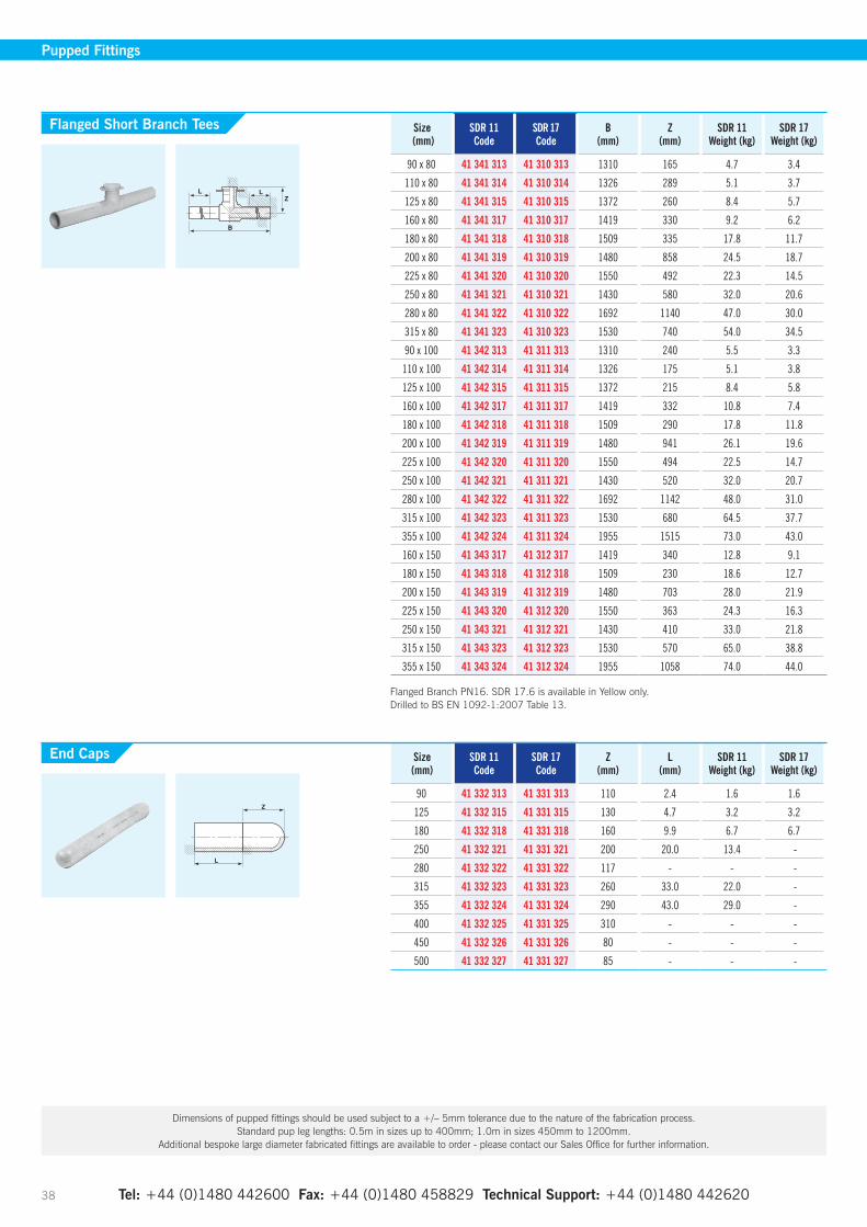
Tel: +44 (0)1480 442600 Fax: +44 (0)1480 458829 Technical Support: +44 (0)1480 442620 38
Size (mm)
SDR 11 Code
SDR 17Code
B(mm)
Z(mm)
SDR 11Weight (kg)
SDR 17Weight (kg)
90 x 80 41 341 313 41 310 313 1310 165 4.7 3.4
110 x 80 41 341 314 41 310 314 1326 289 5.1 3.7
125 x 80 41 341 315 41 310 315 1372 260 8.4 5.7
160 x 80 41 341 317 41 310 317 1419 330 9.2 6.2
180 x 80 41 341 318 41 310 318 1509 335 17.8 11.7
200 x 80 41 341 319 41 310 319 1480 858 24.5 18.7
225 x 80 41 341 320 41 310 320 1550 492 22.3 14.5
250 x 80 41 341 321 41 310 321 1430 580 32.0 20.6
280 x 80 41 341 322 41 310 322 1692 1140 47.0 30.0
315 x 80 41 341 323 41 310 323 1530 740 54.0 34.5
90 x 100 41 342 313 41 311 313 1310 240 5.5 3.3
110 x 100 41 342 314 41 311 314 1326 175 5.1 3.8
125 x 100 41 342 315 41 311 315 1372 215 8.4 5.8
160 x 100 41 342 317 41 311 317 1419 332 10.8 7.4
180 x 100 41 342 318 41 311 318 1509 290 17.8 11.8
200 x 100 41 342 319 41 311 319 1480 941 26.1 19.6
225 x 100 41 342 320 41 311 320 1550 494 22.5 14.7
250 x 100 41 342 321 41 311 321 1430 520 32.0 20.7
280 x 100 41 342 322 41 311 322 1692 1142 48.0 31.0
315 x 100 41 342 323 41 311 323 1530 680 64.5 37.7
355 x 100 41 342 324 41 311 324 1955 1515 73.0 43.0
160 x 150 41 343 317 41 312 317 1419 340 12.8 9.1
180 x 150 41 343 318 41 312 318 1509 230 18.6 12.7
200 x 150 41 343 319 41 312 319 1480 703 28.0 21.9
225 x 150 41 343 320 41 312 320 1550 363 24.3 16.3
250 x 150 41 343 321 41 312 321 1430 410 33.0 21.8
315 x 150 41 343 323 41 312 323 1530 570 65.0 38.8
355 x 150 41 343 324 41 312 324 1955 1058 74.0 44.0
Flanged Branch PN16. SDR 17.6 is available in Yellow only. Drilled to BS EN 1092-1:2007 Table 13.
Flanged Short Branch Tees
Pupped Fittings
Dimensions of pupped fittings should be used subject to a +/– 5mm tolerance due to the nature of the fabrication process. Standard pup leg lengths: 0.5m in sizes up to 400mm; 1.0m in sizes 450mm to 1200mm.
Additional bespoke large diameter fabricated fittings are available to order - please contact our Sales Office for further information.
Size (mm)
SDR 11 Code
SDR 17 Code
Z(mm)
L(mm)
SDR 11Weight (kg)
SDR 17Weight (kg)
90 41 332 313 41 331 313 110 2.4 1.6 1.6
125 41 332 315 41 331 315 130 4.7 3.2 3.2
180 41 332 318 41 331 318 160 9.9 6.7 6.7
250 41 332 321 41 331 321 200 20.0 13.4 -
280 41 332 322 41 331 322 117 - - -
315 41 332 323 41 331 323 260 33.0 22.0 -
355 41 332 324 41 331 324 290 43.0 29.0 -
400 41 332 325 41 331 325 310 - - -
450 41 332 326 41 331 326 80 - - -
500 41 332 327 41 331 327 85 - - -
End Caps
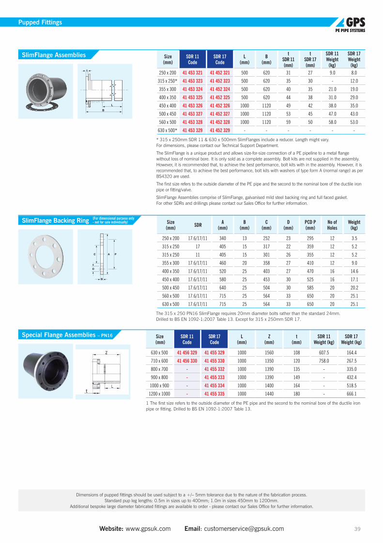
Website: www.gpsuk.com Email: [email protected] 39
Size (mm) SDR A
(mm)B
(mm)C
(mm)D
(mm)PCD P(mm)
No ofHoles
Weight (kg)
250 x 200 17.6/17/11 340 13 252 23 295 12 3.5
315 x 250 17 405 15 317 22 359 12 5.2
315 x 250 11 405 15 301 26 355 12 5.2
355 x 300 17.6/17/11 460 20 358 27 410 12 9.0
400 x 350 17.6/17/11 520 25 403 27 470 16 14.6
450 x 400 17.6/17/11 580 25 453 30 525 16 17.1
500 x 450 17.6/17/11 640 25 504 30 585 20 20.2
560 x 500 17.6/17/11 715 25 564 33 650 20 25.1
630 x 500 17.6/17/11 715 25 564 33 650 20 25.1
The 315 x 250 PN16 SlimFlange requires 20mm diameter bolts rather than the standard 24mm. Drilled to BS EN 1092-1:2007 Table 13. Except for 315 x 250mm SDR 17.
SlimFlange Backing Ring
Pupped Fittings
Size (mm)
SDR 11Code
SDR 17Code
L(mm)
B(mm)
tSDR 11(mm)
tSDR 17(mm)
SDR 11Weight
(kg)
SDR 17Weight
(kg)250 x 200 41 453 321 41 452 321 500 620 31 27 9.0 8.0
315 x 250* 41 453 323 41 452 323 500 620 35 30 - 12.0
355 x 300 41 453 324 41 452 324 500 620 40 35 21.0 19.0
400 x 350 41 453 325 41 452 325 500 620 44 38 31.0 29.0
450 x 400 41 453 326 41 452 326 1000 1120 49 42 38.0 35.0
500 x 450 41 453 327 41 452 327 1000 1120 53 45 47.0 43.0
560 x 500 41 453 328 41 452 328 1000 1120 59 50 58.0 53.0
630 x 500* 41 453 329 41 452 329 - - - - - -
* 315 x 250mm SDR 11 & 630 x 500mm SlimFlanges include a reducer. Length might vary. For dimensions, please contact our Technical Support Department.
The SlimFlange is a unique product and allows size-for-size connection of a PE pipeline to a metal flange without loss of nominal bore. It is only sold as a complete assembly. Bolt kits are not supplied in the assembly. However, it is recommended that, to achieve the best performance, bolt kits with in the assembly. However, it is recommended that, to achieve the best performance, bolt kits with washers of type form A (normal range) as per BS4320 are used.
The first size refers to the outside diameter of the PE pipe and the second to the nominal bore of the ductile iron pipe or fitting/valve.
SlimFlange Assemblies comprise of SlimFlange, galvanised mild steel backing ring and full faced gasket. For other SDRs and drillings please contact our Sales Office for further information.
SlimFlange Assemblies
(For dimensional purpose only - not for sale individually)
B
A PC
D
Dimensions of pupped fittings should be used subject to a +/– 5mm tolerance due to the nature of the fabrication process. Standard pup leg lengths: 0.5m in sizes up to 400mm; 1.0m in sizes 450mm to 1200mm.
Additional bespoke large diameter fabricated fittings are available to order - please contact our Sales Office for further information.
Size (mm)
SDR 11Code
SDR 17Code
L(mm)
Z(mm)
t(mm)
SDR 11Weight (kg)
SDR 17Weight (kg)
630 x 500 41 456 329 41 455 329 1000 1560 108 607.5 164.4
710 x 600 41 456 330 41 455 330 1000 1350 120 758.0 267.5
800 x 700 - 41 455 332 1000 1390 135 - 335.0
900 x 800 - 41 455 333 1000 1390 149 - 432.4
1000 x 900 - 41 455 334 1000 1400 164 - 518.5
1200 x 1000 - 41 455 335 1000 1440 180 - 666.1
1 The first size refers to the outside diameter of the PE pipe and the second to the nominal bore of the ductile iron pipe or fitting. Drilled to BS EN 1092-1:2007 Table 13.
Special Flange Assemblies – PN16

Tel: +44 (0)1480 442600 Fax: +44 (0)1480 458829 Technical Support: +44 (0)1480 442620 40
Pupped Fittings
Dimensions of pupped fittings should be used subject to a +/– 5mm tolerance due to the nature of the fabrication process. Standard pup leg lengths: 0.5m in sizes up to 400mm; 1.0m in sizes 450mm to 1200mm.
Additional bespoke large diameter fabricated fittings are available to order - please contact our Sales Office for further information.
Size(mm)
SDR 11 Code
SDR 17 Code
SDR 21 Code
L(mm)
Z(mm)
SDR 11Weight (kg)
SDR 17Weight (kg)
SDR 21Weight (kg)
90 41 244 313 41 243 313 - 500 617 2.4 1.6 -
110 41 244 314 41 243 314 - 500 643 3.9 2.7 -
125 41 244 315 41 243 315 - 500 663 5.0 4.0 -
160 41 244 317 41 243 317 41 248 317 500 708 9.0 6.0 5.0
180 41 244 318 41 243 318 41 248 318 500 734 12.0 8.0 7.0
200 41 244 319 41 243 319 41 248 319 500 760 18.0 12.0 10.0
225 41 244 320 41 243 320 41 248 320 500 793 20.0 14.0 11.0
250 41 244 321 41 243 321 41 248 321 500 825 26.0 17.0 14.0
280 41 244 322 41 243 322 41 248 322 500 864 32.0 22.0 17.0
315 41 244 323 41 243 323 41 248 323 500 907 42.0 29.0 23.0
355 41 244 324 41 243 324 41 248 324 500 962 56.0 38.0 30.0
400 41 244 325 41 243 325 41 248 325 500 1020 75.0 51.0 39.0
450 41 244 326 41 243 326 41 248 326 1000 1585 153.0 103.0 81.0
500 41 244 327 41 243 327 41 248 327 1000 1650 195.0 132.0 102.0
560 41 244 328 41 243 328 41 248 328 1000 1729 255.0 170.0 131.0
630 41 244 329 41 243 329 41 248 329 1000 1820 335.0 230.0 177.0
710 41 244 330 41 243 330 41 248 330 1000 1929 450.0 305.0 259.0
800 - 41 243 332 41 248 332 1000 2041 - 405.0 344.0
900 - 41 243 333 41 248 333 1000 2171 - 567.8 462.0
1000 - 41 243 334 41 248 334 1000 2301 - 730.8 595.0
1200 - 41 243 335 41 248 335 1000 tbc - 1152.0 940.0
We can suppply longer legs for some butt-fusion machines or shorter (long spigot) for Electrofusion. R = Radius of curvature = approx 1.5 x D (the pipe size) For water applications, from 355mm and above, GPS recommend to de-rate the pressure rating of 22.5°, 45° and 90° mitred bends to 0.8 x the pipe rating from which it was made.
Size(mm)
SDR 11 Code
SDR 17 Code
SDR 21 Code
L(mm)
Z(mm)
SDR 11Weight (kg)
SDR 17Weight (kg)
SDR 21Weight (kg)
90 41 242 313 41 241 313 - 500 538 2.3 1.6 -
110 41 242 314 41 241 314 - 500 546 3.5 2.4 -
125 41 242 315 41 241 315 - 500 553 5.0 3.0 -
160 41 242 317 41 241 317 41 247 317 500 568 8.0 6.0 5.0
180 41 242 318 41 241 318 41 247 318 500 576 10.0 7.0 6.0
200 41 242 319 41 241 319 41 247 319 500 584 13.3 9.0 7.4
225 41 242 320 41 241 320 41 247 320 500 595 17.0 12.0 9.0
250 41 242 321 41 241 321 41 247 321 500 606 20.0 14.0 12.0
280 41 242 322 41 241 322 41 247 322 500 618 25.0 17.0 15.0
315 41 242 323 41 241 323 41 247 323 500 632 33.0 22.0 19.0
355 41 242 324 41 241 324 41 247 324 500 650 42.0 29.0 25.0
400 41 242 325 41 241 325 41 247 325 500 669 55.0 37.0 33.0
450 41 242 326 41 241 326 41 247 326 1000 1191 124.0 84.0 42.0
500 41 242 327 41 241 327 41 247 327 1000 1211 156.0 106.0 89.0
560 41 242 328 41 241 328 41 247 328 1000 1237 200.0 131.0 114.0
630 41 242 329 41 241 329 41 247 329 1000 1266 260.0 175.0 147.0
710 41 242 330 41 241 330 41 247 330 1000 1300 340.0 230.0 191.0
800 - 41 241 332 41 247 332 1000 1339 - 300.0 249.0
900 - 41 241 333 41 247 333 1000 1380 - 399.6 325.0
1000 - 41 241 334 41 247 334 1000 1422 - 505.9 412.0
1200 - 41 241 335 41 247 335 1000 1507 - 769.2 628.0
We can suppply longer legs for some butt-fusion machines or shorter (long spigot) for Electrofusion. R = Radius of curvature = approx 1.5 x D (the pipe size) For water applications, from 355mm and above, GPS recommend to de-rate the pressure rating of 22.5°, 45° and 90° mitred bends to 0.8 x the pipe rating from which it was made.
90º Mitred Elbows
45º Mitred Elbows

Website: www.gpsuk.com Email: [email protected] 41
Size(mm)
SDR 11 Code
SDR 17 Code
SDR 21 Code
L(mm)
Z(mm)
SDR 11Weight (kg)
SDR 17Weight (kg)
SDR 21Weight (kg)
90 41 317 313 41 316 313 - 500 509 2.2 1.5 -
110 41 317 314 41 316 314 - 500 511 3.2 2.2 -
125 41 317 315 41 316 315 - 500 513 4.2 2.8 -
160 41 317 317 41 316 317 41 246 317 500 516 7.0 5.0 4.0
180 41 317 318 41 316 318 41 246 318 500 518 9.0 6.0 5.0
200 41 317 319 41 316 319 41 246 319 500 520 11.6 7.8 6.4
225 41 317 320 41 316 320 41 246 320 500 523 15.0 10.0 8.0
250 41 317 321 41 316 321 41 246 321 500 525 18.0 12.0 10.0
280 41 317 322 41 316 322 41 246 322 500 528 28.0 19.0 12.0
315 41 317 323 41 316 323 41 246 323 500 531 29.0 20.0 16.0
355 41 317 324 41 316 324 41 246 324 500 536 35.0 30.0 20.0
400 41 317 325 41 316 325 41 246 325 500 540 45.0 31.0 26.0
450 41 317 326 41 316 326 41 246 326 1000 1045 110.0 75.0 62.0
500 41 317 327 41 316 327 41 246 327 1000 1050 136.0 92.0 77.0
560 41 317 328 41 316 328 41 246 328 1000 1055 172.0 113.0 97.0
630 41 317 329 41 316 329 41 246 329 1000 1063 220.0 150.0 123.0
710 41 317 330 41 316 330 41 246 330 1000 1068 285.0 190.0 157.0
800 - 41 316 332 41 246 332 1000 1080 - 245.0 201.0
900 - 41 316 333 41 246 333 1000 1090 - 315.5 257.0
1000 - 41 316 334 41 246 334 1000 1099 - 393.3 320.0
1200 - 41 316 335 41 246 335 1000 1119 - 576.3 470.0
We can suppply longer legs for some butt-fusion machines or shorter (long spigot) for Electrofusion. R = Radius of curvature = approx 1.5 x D (the pipe size) For water applications, from 355mm and above, GPS recommend to de-rate the pressure rating of 22.5°, 45° and 90° mitred bends to 0.8 x the pipe rating from which it was made.
Size(mm)
SDR 11 Code
SDR 17 Code
SDR 21 Code
L(mm)
Z(mm)
SDR 11Weight (kg)
SDR 17Weight (kg)
SDR 21Weight (kg)
90 41 298 313 41 297 313 - 500 505 2.1 1.5 -
110 41 298 314 41 297 314 - 500 506 3.2 2.2 -
125 41 298 315 41 297 315 - 500 506 4.1 2.8 -
160 41 298 317 41 297 317 41 245 317 500 508 7.0 5.0 4.0
180 41 298 318 41 297 318 41 245 318 500 509 9.0 6.0 5.0
200 41 298 319 41 297 319 41 245 319 500 510 11.3 7.7 6.3
225 41 298 320 41 297 320 41 245 320 500 511 14.0 10.0 8.0
250 41 298 321 41 297 321 41 245 321 500 512 17.0 12.0 10.0
280 41 298 322 41 297 322 41 245 322 500 514 21.0 15.0 12.0
315 41 298 323 41 297 323 41 245 323 500 516 21.0 15.0 16.0
355 41 298 324 41 297 324 41 245 324 500 518 34.0 29.0 20.0
400 41 298 325 41 297 325 41 245 325 500 520 44.0 30.0 25.0
450 41 298 326 41 297 326 41 245 326 1000 1022 110.0 75.0 61.0
500 41 298 327 41 297 327 41 245 327 1000 1025 133.0 90.0 75.0
560 41 298 328 41 297 328 41 245 328 1000 1026 168.0 110.0 94.0
630 41 298 329 41 297 329 41 245 329 1000 1031 215.0 145.0 120.0
710 41 298 330 41 297 330 41 245 330 1000 1035 275.0 185.0 152.0
800 - 41 297 332 41 245 332 1000 1040 - 235.0 194.0
900 - 41 297 333 41 245 333 1000 1044 - 315.5 245.0
1000 - 41 297 334 41 245 334 1000 1049 - 393.3 308.0
1200 - 41 297 335 41 245 335 1000 1059 - 576.3 445.0
We can suppply longer legs for some butt-fusion machines or shorter (long spigot) for Electrofusion. R = Radius of curvature = approx 1.5 x D (the pipe size) For water applications, from 355mm and above, GPS recommend to de-rate the pressure rating of 22.5°, 45° and 90° mitred bends to 0.8 x the pipe rating from which it was made.
22½º Mitred Elbows
11¼º Mitred Elbows
Pupped Fittings
Dimensions of pupped fittings should be used subject to a +/– 5mm tolerance due to the nature of the fabrication process. Standard pup leg lengths: 0.5m in sizes up to 400mm; 1.0m in sizes 450mm to 1200mm.
Additional bespoke large diameter fabricated fittings are available to order - please contact our Sales Office for further information.

Tel: +44 (0)1480 442600 Fax: +44 (0)1480 458829 Technical Support: +44 (0)1480 442620 42
Potable Water Fittings
Accessories
Size* (mm) SDR Product
CodeA
(mm)B
(mm)C
(mm)D
(mm)PCD P(mm)
No ofHoles
63 x 50 PN10/16 11 53 856 311 165 8 78 18 125 463 x 80 PN10/16 11 53 856 411 200 8 78 18 160 8
75 x 65 PN10/1617 53 857 312 185 8 92 18 145 411 53 856 312 185 12.5 92 18 145 4
90 x 80 PN10/1617 53 857 313 200 8 108 18 160 811 53 856 313 200 15 108 18 160 8
110 x 100 PN10/1617 53 857 314 220 8 128 18 180 811 53 856 314 220 15 128 18 180 8
125 x 100 PN10/1617 53 857 315 220 8 135 18 180 811 53 856 315 220 15 135 18 180 8
160 x 150 PN10/1617 53 857 317 285 10 178 22 240 811 53 856 317 285 20 178 22 240 8
180 x 150 PN10/1617 53 857 318 285 10 185 22 240 811 53 856 318 285 20 185 22 240 8
200 x 200 PN1617 53 859 320 340 10 238 22 295 1211 53 858 320 340 20 238 22 295 12
225 x 200 PN1617 53 859 320 340 10 238 22 295 1211 53 858 320 340 20 238 22 295 12
250 x 250 PN1617 53 859 321 405 15 288 26 355 1211 53 858 321 405 25 288 26 355 12
280 x 250 PN1617 53 859 322 405 20 294 26 355 1211 53 858 322 405 25 294 26 355 12
315 x 300 PN1617 53 859 323 460 20 338 26 410 1211 53 858 323 460 25 338 26 410 12
* The first size refers to the outside diameter of the PE pipe and the second to the nominal bore of the ductile pipe or fitting/valve. Drilled to BS EN 1092-1:2007 Table 13.
Size* (mm)
Product Code
A(mm)
B(mm)
C(mm)
Weight (kg)
63 x 50 PN10/16 53 953 311 165 3 61 0.175 x 65 PN10/16 53 953 312 185 3 77 0.190 x 80 PN10/16 53 953 313 200 3 89 0.1
110 x 100 PN10/16 53 953 314 220 3 100 0.1125 x 100 PN10/16 53 953 315 220 3 115 0.2160 x 150 PN10/16 53 953 317 285 3 169 0.2180 x 150 PN10/16 53 953 318 285 3 169 0.2
200 x 200 PN16 53 954 320 340 3 220 0.2225 x 200 PN16 53 954 320 340 3 220 0.2250 x 250 PN16 53 954 321 405 3 250 0.2280 x 250 PN16 53 954 322 405 3 273 0.2315 x 300 PN16 53 954 323 460 3 300 0.2
EPDM for Water. * The first size refers to the outside diameter of the PE pipe and the second to the nominal bore of the ductile pipe or fitting/valve. In some sizes, gaskets may be supplied as inside bolt circle rather than full faced.
Galvanised Backing Rings for Water
Gaskets
Product Code Weight (kg)
53 590 100 0.5
Suitable for 25mm and 32mm pipe coils.
Service Coil Dispenser Bags

Tel: +44 (0)1480 442600 Fax: +44 (0)1480 458829 Technical Support: +44 (0)1480 442620 Website: www.gpsuk.com Email: [email protected] 43
Potable Water Fittings
Installation and technical GuidelinesIt is not just the quality of our product offering that is unrivalled in the industry, our exceptional technical support matches the high service levels we demand as a company. Our experienced support teams work with customers at every stage of the process to ensure every project is completed to the highest possible standards.
To assist specifiers, contractors and end clients when working with PE pipe systems, our dedicated technical engineers have put together a comprehensive guide outlining the process of installing PE pipelines, from initial specification advice through to step-by-step jointing guides and handling and storage details.
Developed as a ‘go to’ reference guide for users of PE pipes, this section covers every aspect that needs to be considered when specifying and installing PE pipes systems. While this is provided as a detailed overview, each project will have its own individual requirements so our technical team is always on hand to provide bespoke advice, training and support for individual schemes.
Electrofusion Jointing Pipe Preparation & Procedures 44-46
Jointing Instructions for Electrofusion 47-51
Jointing Instructions for Large Diameter Electrofusion Couplers 52-54
Jointing Procedures for Top Loading Tapping Tees 55-56
Assembly & Operating Instructions for Friatop Clamping Unit for Branch Saddle without Underclamp 57-59
Butt Fusion Jointing Procedures 60-65
Flanged Connections 66-67
Repair Section Including Squeeze-Off 68-69
Duck Foot Bend Assembly 70
Handling and Storage 71-74
Pressure Ratings & Flow Characteristics 80-81
Pressure Testing 82
Design 83-87
Product Marking 88
Quality and Environmental Standards 89-90
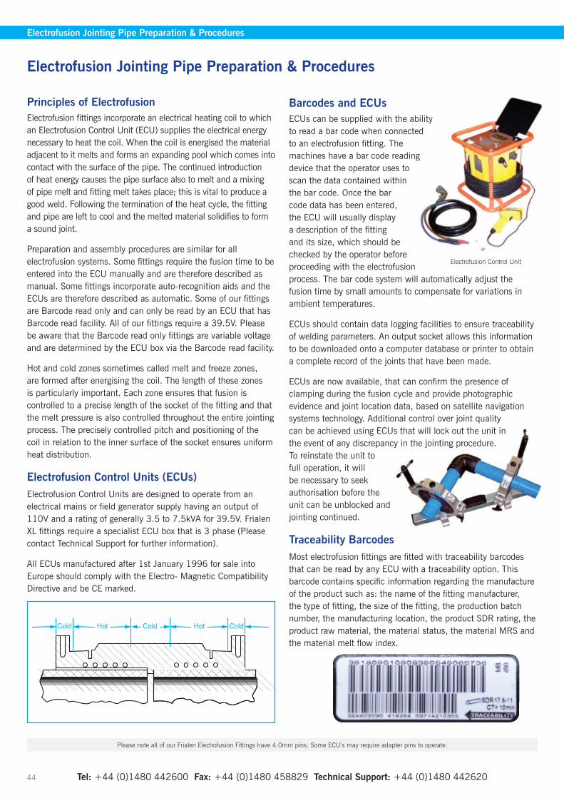
Tel: +44 (0)1480 442600 Fax: +44 (0)1480 458829 Technical Support: +44 (0)1480 442620 44
Electrofusion Jointing Pipe Preparation & Procedures
Electrofusion Jointing Pipe Preparation & Procedures
Principles of ElectrofusionElectrofusion fittings incorporate an electrical heating coil to which an Electrofusion Control Unit (ECU) supplies the electrical energy necessary to heat the coil. When the coil is energised the material adjacent to it melts and forms an expanding pool which comes into contact with the surface of the pipe. The continued introduction of heat energy causes the pipe surface also to melt and a mixing of pipe melt and fitting melt takes place; this is vital to produce a good weld. Following the termination of the heat cycle, the fitting and pipe are left to cool and the melted material solidifies to form a sound joint.
Preparation and assembly procedures are similar for all electrofusion systems. Some fittings require the fusion time to be entered into the ECU manually and are therefore described as manual. Some fittings incorporate auto-recognition aids and the ECUs are therefore described as automatic. Some of our fittings are Barcode read only and can only be read by an ECU that has Barcode read facility. All of our fittings require a 39.5V. Please be aware that the Barcode read only fittings are variable voltage and are determined by the ECU box via the Barcode read facility.
Hot and cold zones sometimes called melt and freeze zones, are formed after energising the coil. The length of these zones is particularly important. Each zone ensures that fusion is controlled to a precise length of the socket of the fitting and that the melt pressure is also controlled throughout the entire jointing process. The precisely controlled pitch and positioning of the coil in relation to the inner surface of the socket ensures uniform heat distribution.
Electrofusion Control Units (ECUs)Electrofusion Control Units are designed to operate from an electrical mains or field generator supply having an output of 110V and a rating of generally 3.5 to 7.5kVA for 39.5V. Frialen XL fittings require a specialist ECU box that is 3 phase (Please contact Technical Support for further information).
All ECUs manufactured after 1st January 1996 for sale into Europe should comply with the Electro- Magnetic Compatibility Directive and be CE marked.
Barcodes and ECUsECUs can be supplied with the ability to read a bar code when connected to an electrofusion fitting. The machines have a bar code reading device that the operator uses to scan the data contained within the bar code. Once the bar code data has been entered, the ECU will usually display a description of the fitting and its size, which should be checked by the operator before proceeding with the electrofusion process. The bar code system will automatically adjust the fusion time by small amounts to compensate for variations in ambient temperatures.
ECUs should contain data logging facilities to ensure traceability of welding parameters. An output socket allows this information to be downloaded onto a computer database or printer to obtain a complete record of the joints that have been made.
ECUs are now available, that can confirm the presence of clamping during the fusion cycle and provide photographic evidence and joint location data, based on satellite navigation systems technology. Additional control over joint quality can be achieved using ECUs that will lock out the unit in the event of any discrepancy in the jointing procedure. To reinstate the unit to full operation, it will be necessary to seek authorisation before the unit can be unblocked and jointing continued.
Traceability BarcodesMost electrofusion fittings are fitted with traceability barcodes that can be read by any ECU with a traceability option. This barcode contains specific information regarding the manufacture of the product such as: the name of the fitting manufacturer, the type of fitting, the size of the fitting, the production batch number, the manufacturing location, the product SDR rating, the product raw material, the material status, the material MRS and the material melt flow index.
Please note all of our Frialen Electrofusion Fittings have 4.0mm pins. Some ECU’s may require adapter pins to operate.
Electrofusion Control Unit
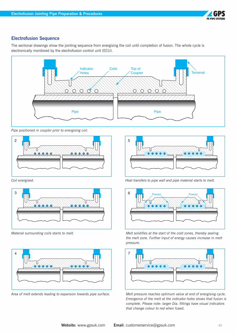
Website: www.gpsuk.com Email: [email protected] 45
Electrofusion Jointing Pipe Preparation & Procedures
Electrofusion SequenceThe sectional drawings show the jointing sequence from energising the coil until completion of fusion. The whole cycle is electronically monitored by the electrofusion control unit (ECU).
1 Indicator Holes Terminal
Top of Coupler
Coils
epiP epiP
2
3
4
5
6 Freeze Freeze
7
1 Indicator Holes Terminal
Top of Coupler
Coils
epiP epiP
2
3
4
5
6 Freeze Freeze
7
Coil energised.
Material surrounding coils starts to melt.
Area of melt extends leading to expansion towards pipe surface.
Pipe positioned in coupler prior to energising coil.
Heat transfers to pipe wall and pipe material starts to melt.
Melt solidifies at the start of the cold zones, thereby sealing the melt zone. Further input of energy causes increase in melt pressure.
Melt pressure reaches optimum value at end of energising cycle. Emergence of the melt at the indicator holes shows that fusion is complete. Please note: larger Dia. fittings have visual indicators that change colour to red when fused.

Tel: +44 (0)1480 442600 Fax: +44 (0)1480 458829 Technical Support: +44 (0)1480 442620 46
Electrofusion Jointing Pipe Preparation & Procedures
Wet Wipes It is preferred that electrofusion joints are made without the use of wet wipes. This is provided that the pipes are freshly scraped, the fitting has just been debagged and the assembly and fusion of the joint follows immediately (see Additional Notes).
If any deviation from the above occurs, which may result in contamination of either the scraped pipe or the debagged fitting then prescribed wet wipes shall be used, - (90% Iso- Propyl Alcohol 10% water mix). Separate fresh wet wipes shall be used for the scraped pipes and the debagged fitting if both are contaminated. The final application of the wipe should be done in axial direction. Whether wiping both scraped pipe or fitting or just one of them, wiped surfaces must be allowed to visibly dry (do not touch the wet surface), then the joint assembled and fused. Failure to allow the jointing surfaces to visually dry will increase the risk of voids at the weld interface.
Note: In butt-fusion jointing wet wipes are not used for cleaning pipes that have already been machined/ trimmed.
Additional NotesWet wipes would not be required provided that:
• Pipe ends are cleaned to remove contamination caused by the installation process
• Pipe ends are mechanically scraped and inspected to ensure that they are free from contamination
• Pipe ends are inserted into the fitting immediately after scraping (within 1 minute)
• Fusion cycle is in accordance with WIS 4-32-08
When using wet wipes the following procedure should be adhered to:
• A pad of 4-5 wipes for each pipe or fitting to be joined should be used to create an effective barrier between the palm of the hand and pipe surface.
• Use pad to remove contamination and allow to evaporate completely from the pipe surface prior to insertion into the fitting
• The process should be repeated using 4 - 5 fresh wipes on each pipe/fitting end to be jointed.
Electrofusion Jointing of Coiled PipePolyethylene pipe coils will tend to exhibit ovality, the extent of which is influenced by many things, but primarily the SDR of the pipe (up to 6% for SDR 11 and 12% for SDR 17).
Recent investment by GPS has allowed us to reduce SDR 17 ovality to less than 5%. Consequently, pipe ends need to be re-rounded and aligned using suitable equipment prior to electrofusion jointing.
To electrofuse joint pipes up to and including 63mm, clamps must be used which align and restrain the pipe.
To electrofuse joint pipes greater than 63mm the equipment must have a re-rounding capability.
Re-rounding clamps are available, which consist of two half shells which are bolted together around the pipe in order to restore its circularity in preparation for jointing.
When using insertion, mole ploughing or directional drilling
techniques, a straight length of pipe may be butt-fusion jointed to the end of the coil to reduce the effects of curvature and ovality. More recently hydraulic re-rounding equipment has been developed to permit a straight length of pipe to be electrofusion jointed to the ends of the coil.
Pipe straighteners, which are fitted to coil trailers, are available, which remove the curvature and ovality from the coiled pipe to facilitate main-laying and jointing.
Pipe insert
Pipe jointing
Hydraulic re-rounding equipment

Website: www.gpsuk.com Email: [email protected] 47
Jointing Instructions for Electrofusion
Jointing Instructions for Electrofusion The instructions that follow describe the procedures used to join Frialen electrofusion fittings to adjacent lengths of pipe and Long Spigot fittings. The procedures described must be read in conjunction with any Code of Practice affecting a particular industry, for example:
• WIS 4-32-08
Equipment• Generator (11OV for the UK and 220V for Europe).
Generally 3.5kVA to 7.5kVA output for 39.5V fittings and 10kVA for 630mm and above
• Electrofusion Control Unit (ECU).
• Clamping equipment.
• Pipe scraping preparation tool capable of removing 0.2 to 0.4mm from the outer surface of the pipe.
• Ancillary equipment such as marker pen, solvent wipes and lint free cloth/paper towel.
• Pipe cutter/saw.
• A shelter to protect the pipe, fittings and ancillary equipment against adverse weather conditions and contamination.
• Pipe end caps.
Temperature/Fusion Time CompensationFrialen products are designed to work on a fixed fusion time for temperatures between -5ºC and +23ºC. Where the time is being entered manually then temperature compensation is not normally necessary within these parameters. The bar code system will automatically adjust the fusion time by small amounts to compensate for variations in ambient temperature.
Terminal Pin Sizes (Frialen)Frialen electrofusion fittings have a standard 4.0mm pin.
Power Supply RequirementsIt is important to ensure that the fitting receives its optimum power requirements in order to affect a satisfactory electrofusion joint. To allow this to happen it is necessary, not only, to have available the correct specification electrofusion control box but also power supply/generator set. Ensure that the output of the power supply is adequate / appropriate for the job being undertaken.
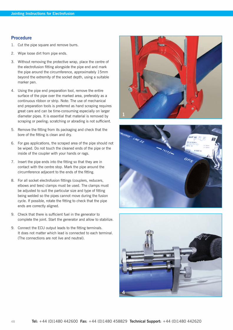
Tel: +44 (0)1480 442600 Fax: +44 (0)1480 458829 Technical Support: +44 (0)1480 442620 48
Jointing Instructions for Electrofusion
Procedure1. Cut the pipe square and remove burrs.
2. Wipe loose dirt from pipe ends.
3. Without removing the protective wrap, place the centre of the electrofusion fitting alongside the pipe end and mark the pipe around the circumference, approximately 15mm beyond the extremity of the socket depth, using a suitable marker pen.
4. Using the pipe end preparation tool, remove the entire surface of the pipe over the marked area, preferably as a continuous ribbon or strip. Note: The use of mechanical end preparation tools is preferred as hand scraping requires great care and can be time-consuming especially on larger diameter pipes. It is essential that material is removed by scraping or peeling; scratching or abrading is not sufficient.
5. Remove the fitting from its packaging and check that the bore of the fitting is clean and dry.
6. For gas applications, the scraped area of the pipe should not be wiped. Do not touch the cleaned ends of the pipe or the inside of the coupler with your hands or rags.
7. Insert the pipe ends into the fitting so that they are in contact with the centre stop. Mark the pipe around the circumference adjacent to the ends of the fitting.
8. For all socket electrofusion fittings (couplers, reducers, elbows and tees) clamps must be used. The clamps must be adjusted to suit the particular size and type of fitting being welded so the pipes cannot move during the fusion cycle. If possible, rotate the fitting to check that the pipe ends are correctly aligned.
9. Check that there is sufficient fuel in the generator to complete the joint. Start the generator and allow to stabilize.
9. Connect the ECU output leads to the fitting terminals. It does not matter which lead is connected to each terminal. (The connections are not live and neutral).
1
3
4
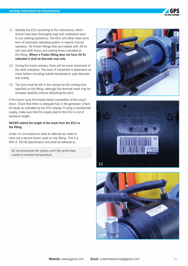
Website: www.gpsuk.com Email: [email protected] 49
Jointing Instructions for Electrofusion
11. Operate the ECU according to the instructions, which should have been thoroughly read and understood prior to any welding operations. The ECU will either have some form of automatic operating system or require manual operation. All Frialen fittings that are marked with 39.5v will have both fusion and cooling times indicated on the fitting. Where a Frialen fitting does not have 39.5v indicated it shall be Barcode read only.
12. During the fusion process, there will be some movement of the weld indicators. The level of movement is dependent on many factors including outside temperature, pipe diameter and ovality.
13. The joint must be left in the clamps for the cooling time specified on the fitting, although the terminal leads may be removed carefully without disturbing the joint.
If the fusion cycle terminates before completion of the count-down. Check that there is adequate fuel in the generator. Check for faults as indicated by the ECU display. If using a transformed supply, make sure that the supply lead to the ECU is not of excessive length.
NEVER extend the length of the leads from the ECU to the fitting.
Under no circumstances shall an attempt be made to carry out a second fusion cycle on any fitting. This is a WIS 4- 32-08 Specification and shall be adhered to.
Do not pressurise the system until the joints have cooled to ambient temperature.
9
11
13
Tel: +44 (0)1480 442600 Fax: +44 (0)1480 458829 Technical Support: +44 (0)1480 442620 50
Pre Jointing Checks• Use equipment that is clean, in good condition and
regularly maintained.
• A mechanical pipe preparation tooling must be used wherever possible.
• Ensure that the cutters/blades of mechanical scrapers are clean and in good condition.
• Check that you have somewhere clean and dry to place tools and equipment during the electrofusion process, and enough access to the work area.
Dos• DO WORK SAFELY
• Do understand the principals of electrofusion (refer to pipe manufacturers details if necessary).
• Do use a shelter and ground sheet, (a suitable anti-slip surface) in both dry and wet conditions to minimise contamination. Use end protection to pipes, (plugs or caps) to eliminate draughts.
• Do always use appropriate clamps for the true alignment, restraining and re-rounding of all pipes, both sticks and coils.
• Do ensure control box voltage is compatible with fitting.
• Do ensure pipe and fittings to be jointed are compatible with each other.
• Do cut pipe ends square for all electrofusion socket fittings.
• Do keep prepared pipe and/or spigot surfaces and fittings clean.
• Do assemble joint and fuse immediately following preparing the pipe.
• Do check that the fusion time displayed by the ECU) matches the fusion time on the fitting when manually input. In the case of Barcode read fittings ensure description matches the fitting.
• Do ensure correct fusion and cooling times are observed and adhered to.
• Do always input the correct operator code and job code to allow for full traceability with Electrofusion Control Units with data retrieval facilities.
• Do mark finished joints with a joint number/data.
• Do ensure that when jointing tapping tees the fitting is correctly positioned on the pipe before fusion. Following the required quality inspections and pressure testing of the welded saddle fitting, the pipe can then be tapped through.
• Do always enter your I.D. details should the ECU request it. Enter your operator and job code to allow full traceability.
• Do always ensure you mark/sign the completed joint with the number issued from the ECU, along with the date if given. This is imperative for full traceability.
Don’ts• Do not start any electrofusion joint unless it can be
completed without interruption.
• Under no circumstances shall an attempt be made to carry out a second fusion cycle on any fitting. This is a WIS 4-32-08 Specification and shall be adhered to.
• Do not use dirty or contaminated fittings.
• Do not use fittings from split or torn bags, all fittings should remain bagged until immediately prior to use.
• Do not ever touch prepared fusion/jointing surfaces.
• Do not allow prepared fusion/jointing surfaces to become wet or damp.
• Do not remove clamps from fitting until cooling time has elapsed.
• Do not remove integral cutter from the stack/saddle (contamination risk).
Jointing Instructions for Electrofusion

Website: www.gpsuk.com Email: [email protected] 51
Health & SafetyGPS make every effort in the design and manufacture of their pipes and fittings to ensure safety whilst in use. The following precautions are however worth bearing in mind:
• Never allow hot polyethylene to come into contact with the skin. In such an event, cold water should be used to cool the affected area. Expert medical advice must be sought.
• Under no circumstances should any attempt be made to remove any material that becomes stuck on the skin without medical supervision. This could result in a more serious injury.
• Heavy pipes, fittings and equipment should not be handled without assistance or mechanical aid. The requirements of Manual Handling Operations Regulation 195 should be adhered to.
• GPS recommend the wearing of Personal Protective Equipment in compliance of statutory legislation such as gloves, safety glasses and safety boots whilst carrying out electrofusion joints.
• Care should be exercised by taking normal precautions when using electrical equipment on site, particularly in wet conditions. ECUs are not intrinsically safe and should not be taken into trenches.
• Normal precautions should be observed when handling electrical equipment and for safety reasons, all 110v portable generator sets should be ‘Centre Tapped’ for site use +55/0/-55 volts.
Always remember that where joint records are automatically stored, these should be downloaded on a regular basis to allow full traceability and integrity of workmanship.
Jointing Instructions for Electrofusion
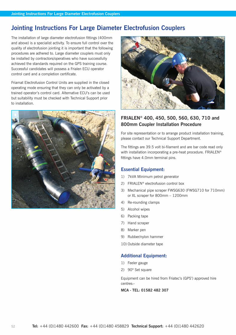
Tel: +44 (0)1480 442600 Fax: +44 (0)1480 458829 Technical Support: +44 (0)1480 442620 52
The installation of large diameter electrofusion fittings (400mm and above) is a specialist activity. To ensure full control over the quality of electrofusion jointing it is important that the following procedures are adhered to. Large diameter couplers must only be installed by contractors/operatives who have successfully achieved the standards required on the GPS training course. Successful candidates will possess a Frialen ECU operator control card and a completion certificate.
Friamat Electrofusion Control Units are supplied in the closed operating mode ensuring that they can only be activated by a trained operator’s control card. Alternative ECU’s can be used but suitability must be checked with Technical Support prior to installation.
FRIALEN® 400, 450, 500, 560, 630, 710 and 800mm Coupler Installation Procedure
For site representation or to arrange product installation training, please contact our Technical Support Department.
The fittings are 39.5 volt bi-filament and are bar code read only with installation incorporating a pre-heat procedure. FRIALEN® fittings have 4.0mm terminal pins.
Essential Equipment:1) 7kVA Minimum petrol generator
2) FRIALEN® electrofusion control box
3) Mechanical pipe scraper FWSG630 (FWSG710 for 710mm) or XL scraper for 800mm – 1200mm
4) Re-rounding clamps
5) Alcohol wipes
6) Packing tape
7) Hand scraper
8) Marker pen
9) Rubber/nylon hammer
10) Outside diameter tape
Additional Equipment:1) Feeler gauge
2) 90º Set square
Equipment can be hired from Friatec’s (GPS’) approved hire centres:-
MCA - TEL: 01582 482 307
Jointing Instructions For Large Diameter Electrofusion Couplers
Jointing Instructions For Large Diameter Electrofusion Couplers

Website: www.gpsuk.com Email: [email protected] 53
FFRIALEN® Large Diameter Electrofusion Couplers Jointing Procedure
Electrofusion Coupler Electrical Check1. Check that the coupler is OK by running the fusion cycle
for 10-12 seconds. Before starting this process start the generator and leave to settle for approximately 1 minute. Ensure that the FRIALEN® ECU is switched OFF before connecting the power supply lead to the generator, then connect it to the generator and switch ON.
2. Before starting it will be necessary to first swipe your user card I.D. card and log on to the ECU. There are two barcode labels on each FRIALEN® fitting. One white and one yellow, Connect the leads of the ECU to one side of the coupler. Once connected swipe the WHITE bar code on the fitting and press START on the ECU. Once 10-12 seconds have elapsed press the Stop button. (This procedure checks the heating element).
Pre-Heat Barcode
Fusion/Traceability/Double Barcode Label
3. If the coupler cuts out during this 10-12 seconds, check the ECU for error messages and rectify accordingly after turning off and disconnecting the ECU from the generator. The most probable cause is a faulty generator or dirty connections/terminals. Should the coupler prove to be faulty then mark the coupler and return to supplier.
Preparing the pipe1. Check the pipe for any abrasions or impact damage that
may be detrimental to the performance of the coupler.
2. Ensure that the pipe end is cut square. It may be useful to use a set-square to be certain - the pipe should not be out of square. Use your outside diameter tape to measure the pipe dimension. The pipe diameter should be greater than the nominal (minimum) diameter specified. Knowing the outside diameter of the pipe will help you to assess how much of the pipe material needs to be scraped off from the outside diameter of the pipe.
3. The FRIALEN® Mechanical Scraper takes off approximately 0.3mm of the pipe surface per rotation. Note: this equates to 0.6mm reduction of the pipe diameter. If using the XL scraper it is 0.5mm per rotation which is a reduction of 1mm of pipe diameter.
4. Once you have established how much material is required to be removed, you can now mark the pipe end for the couplers insertion depth.
5. Before scraping takes place, clean the surface of the pipe to remove as much grease, oil or surface dirt as possible.
6. Use your hand scraper to create a chamfer on the leading edge of the pipe and remove all swarf from the pipe. This will provide a smooth leading edge to assist with the installation of the coupler.
7. Mark the pipe end for the couplers insertion depth (1⁄2 coupler Iength plus 5mm). Use wavy lines to help identify the area that needs to be scraped. If the coupler is to be used for a repair, the whole length of the coupler should be scraped.
8. Check that the scraper blade is in good condition. Worn blades must be replaced. Scrape the surface of the pipe to remove any dirt and the oxidised layer the required number of times, but before the final scrape, try the coupler on the pipe and check the fit and establish any “pinch points”.
9. Scrape off any remaining line markings using hand scraper (grooves and scratches should not be present on the area to be fused) and then use the alcohol wipes to clean the outside surface of the pipe. Use separate wipes to clean the inside of the coupler. All traces of the cleaner should be allowed to evaporate completely prior to the fusion process continuing.
10. Do not touch the cleaned ends of the pipe or the inside of the coupler with your hands or rags.
11. Protect the end against the ingress of dirt, dust or water.
Jointing Instructions For Large Diameter Electrofusion Couplers
Tel: +44 (0)1480 442600 Fax: +44 (0)1480 458829 Technical Support: +44 (0)1480 442620 54
Final Preparation1. We have now completed the final preparation before starting
the fusion process. Fusion should be conducted immediately after scraping.
2. Measure ½ a coupler length on the end of each of the pipe ends to be joined and mark this onto the pipe using a marker pen. Set the hydraulic re-rounding clamp to the pipe behind the mark.
3. Place coupler onto the end of the pipe and establish where pipe ovality may interfere with placing the coupler onto the pipe. It may be necessary to mark the pipe end and hand scrape the affected area.
4. Deburr both the inner and outer end edges of the pipe using the hand scraper before proceeding. You are now ready to install the coupler onto the pipe. Frialen couplers are designed to be an interference fit and it may be necessary to tap the coupler with care onto the pipe using a nylon or rubber mallet. Care must be taken not to allow the coupler to ‘tilt’ on the pipe during this final phase. Knock the coupler on using the rerounding clamp as a stop.
5. Control localised gaps by using packing tape to close the annular gap between the pipe and coupler. This will help keep any warmth inside the coupler, thus aiding the preheat process to close any gaps caused by ovality or pipe tolerances.
6. Before starting the fusion process ensure, that both the pipe and the coupler are adequately supported to stop any ‘sagging’ during the fusion process and avoid any tension on the coupler.
Please Note: Additional Points to Remember
1. Handle couplers and fittings with care. Do not drop or throw.
2. Always store in a clean dry place. Never outside.
3. All fittings must be pre-heated prior to the main electrofusion weld. Take care to adhere to the minimum and maximum times between pre-heat and final electrofusion.
4. Always ensure that the generator has sufficient fuel and does not run out during fusion as this could lead to a failed joint.
5. The weld indicators do not always fully protrude from the fitting; this does not indicate a weld failure.
Electrofusion Process1. Now connect up the Frialen ECU as previously described.
Connect the terminal leads to the coupler and swipe the yellow bar code this initiates the pre-heat cycle of the coupler. Confirm the details on the ECU display and press Start button. Once completed allow the electrofused side to warm (heat soak) for a minimum of 15 minutes and a maximum of 20 minutes, this will allow the pipe enough time to expand inside the coupler. It may be necessary to preheat more than once. Up to a maximum of three times is permissible (depending on wall thickness/SDR).
2. Each preheat cycle should bridge a gap of approximately 1mm between the pipe and coupler.
3. Check that all adequate precautions to reduce any gaps to acceptable limits have been taken. The maximum air gap between the pipe and the electrofusion fitting should be no more than 2mm. Particular care should be taken if a feeler gauge is used as these can be a source of contamination to the previously cleaned surfaces and can damage the wires of the electrofusion fitting.
You can now proceed with fusion process. To begin fusion, return to the first side and reconnect leads to the terminal and swipe the white bar code. Confirm the details on ECU display and press the green Start button.
4. Repeat steps 1 to 3 for the other side. Precaution must be made to prevent any movement bending or pulling on the coupler to avoid tension on the joint during the fusion cycle.
5. It is also important not to disturb the joint during its fusion or cooling period.
Frialen fittings are equipped with a swell indicator on each side, adjacent to the terminals. The swell indicator signalises the fusion process by changing its colour to red and increasing its volume.
6. Pipes and fittings may be joined between -10ºC and +45ºC for sizes up to and including 630mm and between 0ºC and +45ºC - for sizes 710mm and above.
7. To ensure the correct sequence of operation during jointing, note the completed stages on the pipe surface.
Datalogging/Fusion Completion1. Download joint data from the electrofusion control unit for
trace ability.
2. Swipe l.D card – log off.
Jointing Instructions For Large Diameter Electrofusion Couplers
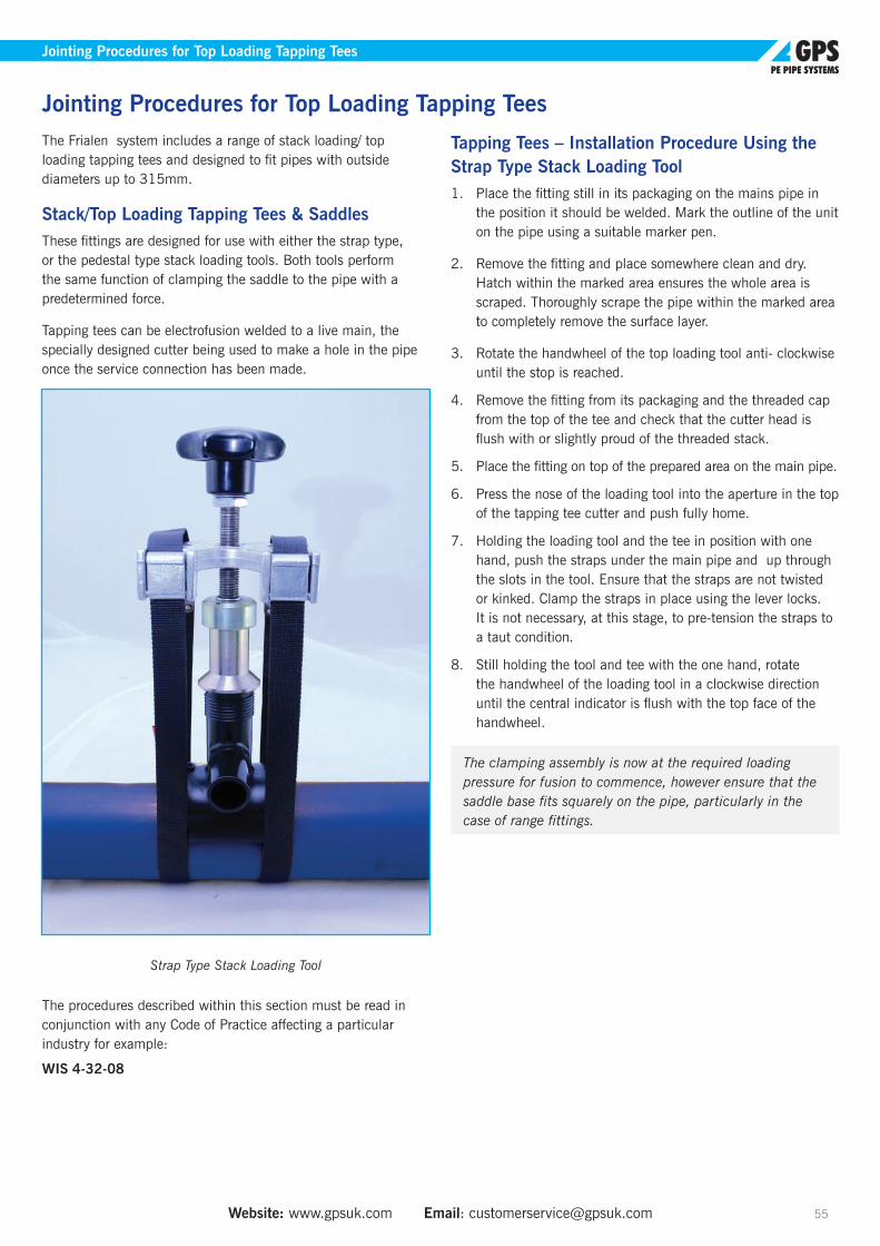
Website: www.gpsuk.com Email: [email protected] 55
The Frialen system includes a range of stack loading/ top loading tapping tees and designed to fit pipes with outside diameters up to 315mm.
Stack/Top Loading Tapping Tees & SaddlesThese fittings are designed for use with either the strap type, or the pedestal type stack loading tools. Both tools perform the same function of clamping the saddle to the pipe with a predetermined force.
Tapping tees can be electrofusion welded to a live main, the specially designed cutter being used to make a hole in the pipe once the service connection has been made.
Strap Type Stack Loading Tool
The procedures described within this section must be read in conjunction with any Code of Practice affecting a particular industry for example:
WIS 4-32-08
Tapping Tees – Installation Procedure Using the Strap Type Stack Loading Tool1. Place the fitting still in its packaging on the mains pipe in
the position it should be welded. Mark the outline of the unit on the pipe using a suitable marker pen.
2. Remove the fitting and place somewhere clean and dry. Hatch within the marked area ensures the whole area is scraped. Thoroughly scrape the pipe within the marked area to completely remove the surface layer.
3. Rotate the handwheel of the top loading tool anti- clockwise until the stop is reached.
4. Remove the fitting from its packaging and the threaded cap from the top of the tee and check that the cutter head is flush with or slightly proud of the threaded stack.
5. Place the fitting on top of the prepared area on the main pipe.
6. Press the nose of the loading tool into the aperture in the top of the tapping tee cutter and push fully home.
7. Holding the loading tool and the tee in position with one hand, push the straps under the main pipe and up through the slots in the tool. Ensure that the straps are not twisted or kinked. Clamp the straps in place using the lever locks. It is not necessary, at this stage, to pre-tension the straps to a taut condition.
8. Still holding the tool and tee with the one hand, rotate the handwheel of the loading tool in a clockwise direction until the central indicator is flush with the top face of the handwheel.
The clamping assembly is now at the required loading pressure for fusion to commence, however ensure that the saddle base fits squarely on the pipe, particularly in the case of range fittings.
Jointing Procedures for Top Loading Tapping Tees
Jointing Procedures for Top Loading Tapping Tees

Tel: +44 (0)1480 442600 Fax: +44 (0)1480 458829 Technical Support: +44 (0)1480 442620 56
Electrofusion Procedure1. Connect the electrofusion control unit (ECU) leads to the
tapping tee and key in the correct fusion time if available, otherwise use the barcode reader.
2. Check the loading pressure is correct by ensuring that the central indicator is still flush with the top face of the spring carrier.
3. Press the fusion start button.
4. On completion of the cycle remove the leads and allow the joint to cool for the required time, as shown on the fitting, before removing the tool.
5. Replace the threaded cap ensuring that the ‘O’ ring seal is in position.
Service Connections – Tapping Tee to Service PipeThe service connections between the tapping tee and the service pipes are made using either service couplers or service reducers in conjunction with a suitable alignment clamp.
The procedure for making a service connection is as described for the electrofusion couplers.
Any hydrostatic/ air pressure tests should be carried out on the service pipe before the hole is cut through the wall of the mains pipe using the integral cutter.
Pedestal Type Stack Loading Tool
Service Connections – Tapping into a Water Main
Tapping into the water main should not be carried out until at least 30 minutes have elapsed following the end of the cooling cycle. After this time period the tapping procedure is as follows:
1. Insert the tapping key into the recess in the top of the metal cutter and turn in a clockwise direction. Continue until the pipe wall is completely cut through (indicated by a reduction in the force necessary to turn the key).
2. Retract the cutter by turning the key in an anti-clockwise direction until the top of the cutter is flush with the top of the threaded stack, showing that the cutter is clear of the branch.
The coupon of material cut from the pipe wall will be retained in the end of the cutter.
• Check that the ‘O’ ring seal is in place in the cap and screw it down hand tight onto the threaded stack of the tee.
Note: Thread Followers - The torque may be high when cutting through the wall of large diameter pipes. Thread followers are available to enable the load to be spread over a greater number of threads, minimising the risk of stripping the moulded threads inside the stack of the tapping tee.
Jointing Procedures for Top Loading Tapping Tees
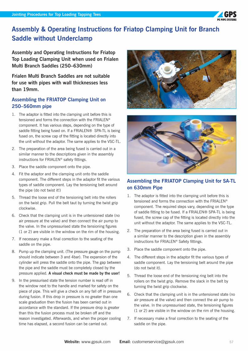
Website: www.gpsuk.com Email: [email protected] 57
Jointing Procedures for Top Loading Tapping Tees
Assembly and Operating Instructions for Friatop Top Loading Clamping Unit when used on Frialen Multi Branch Saddles (250–630mm)
Frialen Multi Branch Saddles are not suitable for use with pipes with wall thicknesses less than 19mm.
Assembling the FRIATOP Clamping Unit on 250–560mm pipe
1. The adaptor is fitted into the clamping unit before this is tensioned and forms the connection with the FRIALEN® component. It has various steps, depending on the type of saddle fitting being fused on. If a FRIALEN® SPA-TL is being fused on, the screw cap of the fitting is located directly into the unit without the adaptor. The same applies to the VSC-TL.
2. The preparation of the area being fused is carried out in a similar manner to the descriptions given in the assembly instructions for FRIALEN® safety fittings.
3. Place the saddle component onto the pipe.
4. Fit the adaptor and the clamping unit onto the saddle component. The different steps in the adaptor fit the various types of saddle component. Lay the tensioning belt around the pipe (do not twist it!)
5. Thread the loose end of the tensioning belt into the rollers on the twist grip. Pull the belt taut by turning the twist grip clockwise.
6. Check that the clamping unit is in the untensioned state (no air pressure at the valve) and then connect the air pump to the valve. In the unpressurised state the tensioning figures (1 or 2) are visible in the window on the rim of the housing.
7. If necessary make a final correction to the seating of the saddle on the pipe.
8. Pump up the clamping unit. (The pressure gauge on the pump should indicate between 3 and 4bar). The expansion of the cylinder will press the saddle onto the pipe. The gap between the pipe and the saddle must be completely closed by the pressure applied. A visual check must be made by the user!
9. In the pressurised state the tension number is read off in the window next to the handle and marked for safety on the piece of pipe. This will give a check on any fall off in pressure during fusion. If this drop in pressure is no greater than one scale graduation then the fusion has been carried out in accordance with the standard. If the pressure drop is greater than this the fusion process must be broken off and the reason investigated. Afterwards, and when the proper cooling time has elapsed, a second fusion can be carried out.
Assembling the FRIATOP Clamping Unit for SA-TL on 630mm Pipe
1. The adaptor is fitted into the clamping unit before this is tensioned and forms the connection with the FRIALEN® component. The required steps vary, depending on the type of saddle fitting to be fused. If a FRIALEN® SPA-TL is being fused, the screw cap of the fitting is located directly into the unit without the adaptor. The same applies to the VSC-TL.
2. The preparation of the area being fused is carried out in a similar manner to the description given in the assembly instructions for FRIALEN® Safety fittings.
3. Place the saddle component onto the pipe.
4. The different steps in the adaptor fit the various types of saddle component. Lay the tensioning belt around the pipe (do not twist it).
5. Thread the loose end of the tensioning ring belt into the rollers on the twist grip. Remove the slack in the belt by turning the twist grip clockwise.
6. Check that the clamping unit is in the untensioned state (no air pressure at the valve) and then connect the air pump to the valve. In the unpressurised state, the tensioning figures (1 or 2) are visible in the window on the rim of the housing.
7. If necessary make a final correction to the seating of the saddle on the pipe.
Assembly & Operating Instructions for Friatop Clamping Unit for Branch Saddle without Underclamp

Tel: +44 (0)1480 442600 Fax: +44 (0)1480 458829 Technical Support: +44 (0)1480 442620 58
8. Check that fitting is loaded fully square to the pipe, failure to do so will mean the fitting will not fully load at one side on the spigot. If excessive movement is experienced it is acceptable to pack around the spigot top between the fitting and the top loading tool with a packing collar made from metal or plastic.
9. Pump up the clamping unit slowly. Once the unit pressure gauge shows 1Bar. Stop the pumping for a minimum of 40 seconds. Again pump the clamping unit until the pressure gauge shows 2Bar. Stop the pumping for a minimum of 40 seconds.
10. Ventilate the system. The indicator on the clamping unit should fall between 1 and 2. Pull the belt again and turn the twist clockwise (see 5). Pump up as described in steps 6 to 9.
The pressure should stay constant and the gap between the saddle and the pipe should be completely closed. The maximum allowable gap between pipe and fitting should be no more than 0.5mm (this can be checked with a feeler gauge). If this is not the case, the final part of the procedure (8) should be repeated. A visual check must be made by a user!
11. In the pressured state the tension number is read off in the window next to the handle and marked for safety on the piece of pipe. This will give a check on any fall off in pressure during fusion. If this drop in pressure is no greater than one scale graduation, then the fusion has been carried out in accordance with the standard. If the pressure drop is greater than this, the fusion process must be stopped and the reason investigated. Afterwards, and when the proper cooling time has elapsed, second fusion can be carried out.
FusionConnect the fusion cable from the fusion unit to the contacts on the saddle and start the fusion process.
During the fusion process the tension number should be checked.
For general safety reasons always stay at a distance of one metre from the point of fusion during the fusion process.
Removing the FRIATOP Clamping UnitAfter fusion has finished, always maintain the joint pressure in accordance with point 9 on page 45 for a 10 minute cooling period. After this, the pressure can be taken off by venting the unit to air and the unit dismantled.
Before drilling, please allow to cool down for 60min (for sizes 250mm to 630mm). If the cooling down time is not adhered to, the saddle can come away from the pipe in the area of the fused joint, therefore a permanently safe fused joint cannot be guaranteed.
WarrantyThe warranty is six months. It will not apply if there are signs of force or inappropriate usage, you must keep in accordance with the operating instructions.
Functional SafetyThe FRIATOP clamping unit has been checked for safe operation before being shipped. The equipment requires very little maintenance. We recommend a half yearly check on all functional parts. The unit should be protected from dirt.
Assembly and Operating Instructions for Friatop Top Loading Clamping Unit when used on Frialen Tapping Tees (250–315mm)FRIALEN® Saddle Components are used with pipes from SDR 17 to SDR 11 from 250mm diameter. They are held in place during fusion by the FRIATOP clamping device.
FL615339 Pressure Tapping Fitting - Top Loading 250mm- 315mm diameter suitable for using as branch connectors onto non-pressurised or pressurised pipelines.
Frialen Top Loading Tapping Tee
For technical reasons FRIALEN® Pressure Tapping Fittings cannot be used with SDR7 pipes.1. Mark out the area of the fusion zone on the pipe (and the
side outlet spigot) and remove the oxide skin by scraping. The fusion zone is the area of pipe covered by the saddle; for a side outlet, it is the insertion depth on the smooth pipe spigot. The oxide skin in the area of the fusion zone, which has formed on the surface of the pipes during storage, must be totally removed before assembly.
If the oxide skin is not completely removed this can lead to an unsatisfactory fused joint which may leak.
A single unbroken removal of the surface is adequate (min. 0.15mm). There should not be any pipe surface damage such as grooves or scratches within the fusion zone.
Assembly & Operating Instructions for Friatop Clamping Unit for Branch Saddle without Underclamp

Website: www.gpsuk.com Email: [email protected] 59
Assembly & Operating Instructions for Friatop Clamping Unit for Branch Saddle without Underclamp Assembly & Operating Instructions for Friatop Clamping Unit for Branch Saddle without Underclamp
Filing or using an emery cloth is not acceptable as this can lead to impurities being embedded in the surface. As a check that the removal of material from the surface is unbroken and covers the full area, we recommend the use of marked lines to check. If during the scraping process areas of the surface are not scraped (e.g. if the pipe is oval) these must be reworked. Protect the cleaned up zone from dirt, soap, grease, water running back and unfavourable weather (e.g. from effects of moisture, the formation of frost).
2. The surfaces of the pipe being fused and the internal surfaces of the fittings must be absolutely clean, dry and free from grease. Immediately before assembly, and after scraping, clean these surfaces with a suitable cleaning fluid, using only absorbent non- fibrous, non-coloured paper. We recommend the use of special PE cleaning fluid.
When using alcohol based cleaners the alcohol content must be a minimum of 99.8%. The cleaner must have evaporated completely before using.
Now, using a marker pen, redraw the line to show the perimeter of the fusion zone on the pipe since previous markings will have been removed by scraping and cleaning. Take care to ensure that the fusion zone remains clean whilst doing this.
The areas to be fused must be clean and dry prior to the fitting being mounted. Avoid touching the cleaned fusion area. Any moisture caused by dew or condensation in the area to be fused must be removed using appropriate means.
3. To assemble the joint, place the saddle onto the prepared surface of the pipe. Fit the clamping device as directed in the operating instructions for Friatop.
Do not take the fitting to be fused from its packaging until just before processing. The packaging protects the component from external damage during transport and storage.
On FRIALEN® Pressure Tapping Fittings the drill setting made at the factory must not be altered before fusing.
After the fusion process has finished always maintain the jointing pressure for a 10 minute cooling period.
4. When using FRIALEN® Pressure Tapping Fittings onto pipes carrying a fluid or gas the following maximum permissible operating pressures must not be exceeded during the fusion process and until cooling down is complete.
Maximum permissible working pressure in bar
Pipe Material PE80 Excel (PE100)
SDR 17 11 17 11
Water Pipe 8 12.5 10 16
Only use ECUs which are designed and authorised by their manufacturer to process FRIALEN® Safety Fittings. The fusion parameters are contained in a bar code which is affixed to the FRIALEN® Safety Fitting. The parameters are entered into the ECU using the reader wand.
The ECU automatically monitors the progress of the fusion process and regulates the electrical energy input to within specified limits.
The fitting fusion indicator only gives an indication that fusion has taken place. The proper progress of the fusion process, however, is only shown by the ECU.
For the sake of general safety always maintain a distance of one metre from the fusion point during the fusion process.
5. The cooling time (CT) given on the components are the cooling times before drilling can commence.
Diameter (mm)
Cooling down time for FRIALEN® Multi Saddle components before pressurising through the outlet
Before Drilling (CT)
250-500 50 minutes 60 minutes
If the waiting times are not complied with, there is a risk of an unsatisfactory fused joint which may leak. Before drilling, the general installation guidelines must be observed.
Frialen Under Clamp Branch and Spigot SaddlesPreparation and fusion procedures are the same as for Frialen Tapping Tees. Tapping is done with commercially available tapping units, incorporating shut-off valves. Please contact our Technical Support Department for further information.
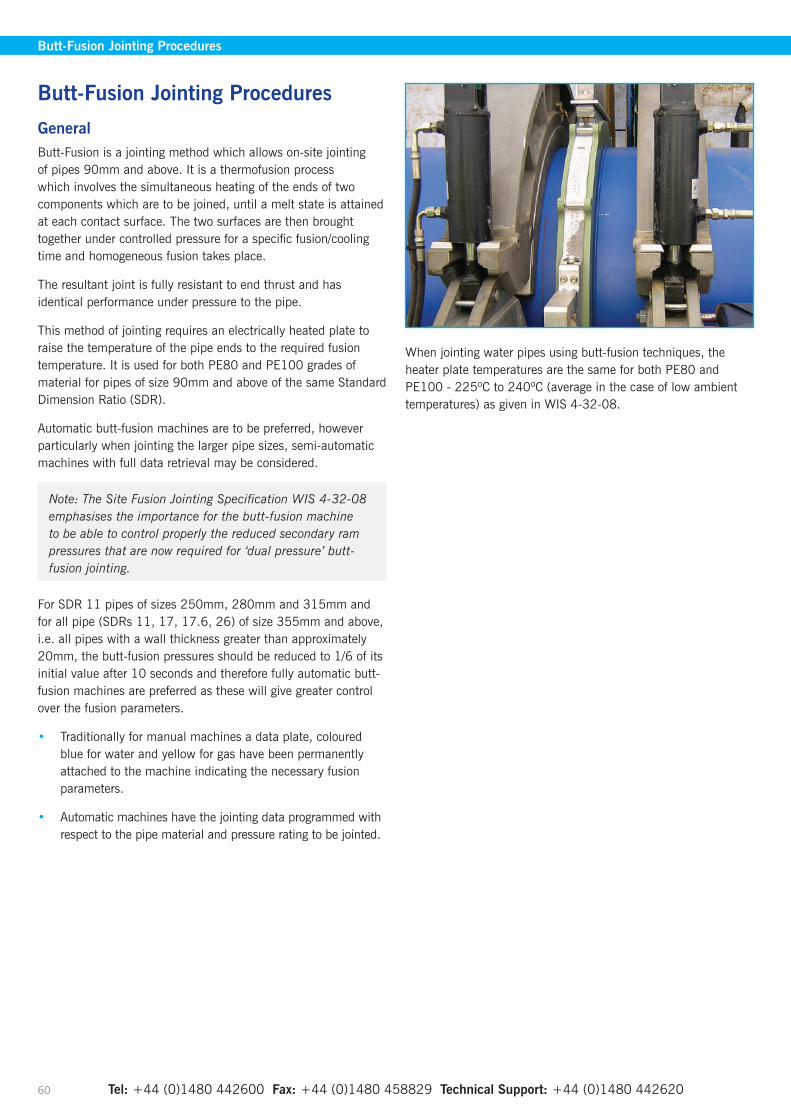
Tel: +44 (0)1480 442600 Fax: +44 (0)1480 458829 Technical Support: +44 (0)1480 442620 60
GeneralButt-Fusion is a jointing method which allows on-site jointing of pipes 90mm and above. It is a thermofusion process which involves the simultaneous heating of the ends of two components which are to be joined, until a melt state is attained at each contact surface. The two surfaces are then brought together under controlled pressure for a specific fusion/cooling time and homogeneous fusion takes place.
The resultant joint is fully resistant to end thrust and has identical performance under pressure to the pipe.
This method of jointing requires an electrically heated plate to raise the temperature of the pipe ends to the required fusion temperature. It is used for both PE80 and PE100 grades of material for pipes of size 90mm and above of the same Standard Dimension Ratio (SDR).
Automatic butt-fusion machines are to be preferred, however particularly when jointing the larger pipe sizes, semi-automatic machines with full data retrieval may be considered.
Note: The Site Fusion Jointing Specification WIS 4-32-08 emphasises the importance for the butt-fusion machine to be able to control properly the reduced secondary ram pressures that are now required for ‘dual pressure’ butt-fusion jointing.
For SDR 11 pipes of sizes 250mm, 280mm and 315mm and for all pipe (SDRs 11, 17, 17.6, 26) of size 355mm and above, i.e. all pipes with a wall thickness greater than approximately 20mm, the butt-fusion pressures should be reduced to 1/6 of its initial value after 10 seconds and therefore fully automatic butt-fusion machines are preferred as these will give greater control over the fusion parameters.
• Traditionally for manual machines a data plate, coloured blue for water and yellow for gas have been permanently attached to the machine indicating the necessary fusion parameters.
• Automatic machines have the jointing data programmed with respect to the pipe material and pressure rating to be jointed.
When jointing water pipes using butt-fusion techniques, the heater plate temperatures are the same for both PE80 and PE100 - 225ºC to 240ºC (average in the case of low ambient temperatures) as given in WIS 4-32-08.
Butt-Fusion Jointing Procedures
Butt-Fusion Jointing Procedures

Website: www.gpsuk.com Email: [email protected] 61
Butt-Fusion Jointing Procedures
Butt-Fusion Jointing Parameters for Water (WIS 4-32-08) Heater Plate Surface Temperature: 225°C to 240°C.Table 1 Single pressure butt-fusion jointing conditions for PE80 and Excel® (PE100).
Outside diameter SDR
Wall thickness
(min)
Interface stress
(initial)
Initial bead size (approx.)
Minimum heat soak
time
Minimum soak
pressure
Heater plate removal time
Interface stress (fusion and cooling
Cooling time in clamps
Additional cooling time for
coiled pipes
Typical final overall bead width (min)
Typical final overall bead width (max)
(mm) (mm) (MPa) (mm) (s) (MPa) (s) (MPa) (min) (min) (mm) (mm)90 17 5.1 0.15 2 110 0 10 0.15 15 5 8 1590 11 8.2 0.15 2 140 0 10 0.15 15 5 9 16
110 17 6.3 0.15 2 125 0 10 0.15 15 5 9 16110 11 10.0 0.15 2 160 0 10 0.15 15 5 10 17125 17 7.1 0.15 2 130 0 10 0.15 15 5 9 16125 11 11.4 0.15 2 175 0 10 0.15 15 5 10 17160 17 9.1 0.15 2 150 0 10 0.15 15 5 9 16160 11 14.6 0.15 2 205 0 10 0.15 15 5 11 18180 17 10.2 0.15 2 160 0 10 0.15 15 5 10 17180 11 16.4 0.15 2 225 0 10 0.15 15 5 11 18225 17 12.8 0.15 2 190 0 10 0.15 15 - 10 17225 11 20.5 0.15 2 265 0 10 0.15 15 - 12 19250 26 9.6 0.15 2 155 0 10 0.15 15 - 9 16250 17 14.2 0.15 2 200 0 10 0.15 15 - 10 17280 26 10.7 0.15 2 170 0 10 0.15 15 - 13 22280 17 15.9 0.15 2 220 0 10 0.15 15 - 14 23315 26 12.1 0.15 2 180 0 10 0.15 15 - 13 22315 17 17.9 0.15 2 240 0 10 0.15 15 - 14 23
Table 2 Dual pressure butt-fusion jointing conditions for PE80 and Excel® (PE100).
Outside diameter SDR
Wall thickness
(min)
Interface stress
(initial)
Initial bead size (approx.)
Minimum heat soak
time
Minimum soak
pressure
Heater plate removal time
Interface stress (fusion and cooling)
Interface stress (cool-ing after 10s)
Cooling time in clamps
Typical final overall bead width (min)
Typical final overall bead width (max)
(mm) (mm) (MPa) (mm) (min) (MPa) (s) (MPa) (MPa) (min) (mm) (mm)250 11 22.7 0.15 2 6 0 10 0.15 0.025 18 15 24280 11 25.4 0.15 3 7 0 10 0.15 0.025 18 16 25315 11 28.6 0.15 3 7 0 10 0.15 0.025 19 17 26355 11 32.2 0.15 3 8 0 10 0.15 0.025 21 18 27400 17 23.7 0.15 3 6 0 10 0.15 0.025 18 15 24400 11 36.3 0.15 3 9 0 10 0.15 0.025 23 18 27450 17 26.7 0.15 3 7 0 10 0.15 0.025 19 16 25450 11 40.9 0.15 3 10 0 10 0.15 0.025 26 19 28500 17 29.7 0.15 3 8 0 10 0.15 0.025 20 17 26500 11 45.4 0.15 3 11 0 10 0.15 0.025 30 20 29560 17 33.2 0.15 3 8 0 10 0.15 0.025 21 17 26560 11 50.8 0.15 3 12 0 10 0.15 0.025 35 22 31630 26 24.1 0.15 3 7 0 10 0.15 0.025 18 16 25630 17 37.4 0.15 3 9 0 10 0.15 0.025 24 18 27630 11 57.2 0.15 3 13 0 10 0.15 0.025 43 23 32710 26 27.2 0.15 3 7 0 10 0.15 0.025 19 16 25710 17 42.2 0.15 3 10 0 10 0.15 0.025 27 19 28800 26 30.6 0.15 3 8 0 10 0.15 0.025 20 17 26800 17 47.4 0.15 3 11 0 10 0.15 0.025 32 20 29900 26 34.4 0.15 3 9 0 10 0.15 0.025 22 18 27900 17 53.3 0.15 3 13 0 10 0.15 0.025 38 22 31
1000 26 38.2 0.15 3 9 0 10 0.15 0.025 24 19 281000 17 59.3 0.15 3 14 0 10 0.15 0.025 45 23 321200 26 45.9 0.15 3 11 0 10 0.15 0.025 31 31 301200 17 71.1 0.15 3 16 0 10 0.15 0.025 63 26 35
NB: All jointing pressures must be calculated by using the effective ram area of the machine in relation to the cross-sectional area of the pipe wall. Effective ram area varies with manufacturer and models. Effective ram area should be marked on each model. Please refer to page XX regarding soak time for thick walled pipe.
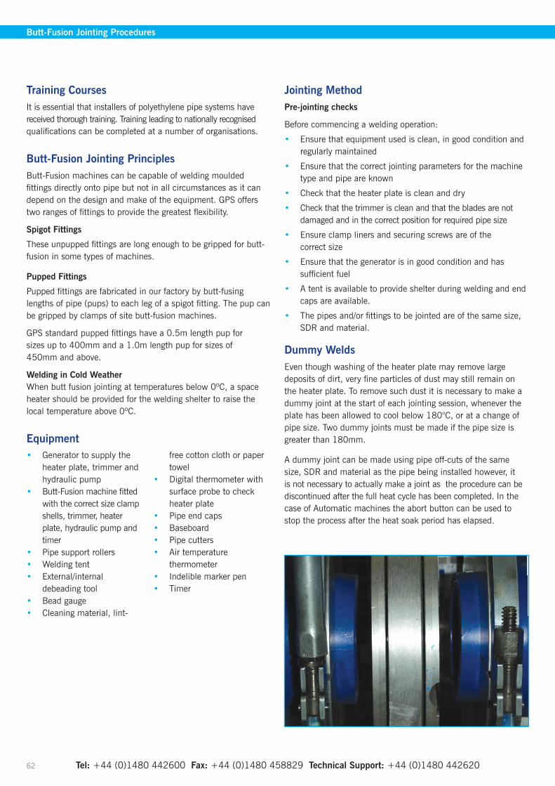
Tel: +44 (0)1480 442600 Fax: +44 (0)1480 458829 Technical Support: +44 (0)1480 442620 62
Training CoursesIt is essential that installers of polyethylene pipe systems have received thorough training. Training leading to nationally recognised qualifications can be completed at a number of organisations.
Butt-Fusion Jointing PrinciplesButt-Fusion machines can be capable of welding moulded fittings directly onto pipe but not in all circumstances as it can depend on the design and make of the equipment. GPS offers two ranges of fittings to provide the greatest flexibility.
Spigot Fittings
These unpupped fittings are long enough to be gripped for butt-fusion in some types of machines.
Pupped Fittings
Pupped fittings are fabricated in our factory by butt-fusing lengths of pipe (pups) to each leg of a spigot fitting. The pup can be gripped by clamps of site butt-fusion machines.
GPS standard pupped fittings have a 0.5m length pup for sizes up to 400mm and a 1.0m length pup for sizes of 450mm and above.
Welding in Cold WeatherWhen butt fusion jointing at temperatures below 0ºC, a space heater should be provided for the welding shelter to raise the local temperature above 0ºC.
Equipment• Generator to supply the
heater plate, trimmer and hydraulic pump
• Butt-Fusion machine fitted with the correct size clamp shells, trimmer, heater plate, hydraulic pump and timer
• Pipe support rollers• Welding tent• External/internal
debeading tool• Bead gauge• Cleaning material, lint-
free cotton cloth or paper towel
• Digital thermometer with surface probe to check heater plate
• Pipe end caps• Baseboard• Pipe cutters• Air temperature
thermometer• Indelible marker pen• Timer
Jointing MethodPre-jointing checks
Before commencing a welding operation:
• Ensure that equipment used is clean, in good condition and regularly maintained
• Ensure that the correct jointing parameters for the machine type and pipe are known
• Check that the heater plate is clean and dry
• Check that the trimmer is clean and that the blades are not damaged and in the correct position for required pipe size
• Ensure clamp liners and securing screws are of the correct size
• Ensure that the generator is in good condition and has sufficient fuel
• A tent is available to provide shelter during welding and end caps are available.
• The pipes and/or fittings to be jointed are of the same size, SDR and material.
Dummy WeldsEven though washing of the heater plate may remove large deposits of dirt, very fine particles of dust may still remain on the heater plate. To remove such dust it is necessary to make a dummy joint at the start of each jointing session, whenever the plate has been allowed to cool below 180°C, or at a change of pipe size. Two dummy joints must be made if the pipe size is greater than 180mm.
A dummy joint can be made using pipe off-cuts of the same size, SDR and material as the pipe being installed however, it is not necessary to actually make a joint as the procedure can be discontinued after the full heat cycle has been completed. In the case of Automatic machines the abort button can be used to stop the process after the heat soak period has elapsed.
Butt-Fusion Jointing Procedures

Website: www.gpsuk.com Email: [email protected] 63
Butt-Fusion Jointing Procedures
Welding Procedure1. With the machine in the open position place the pipes in
the clamps with the ends adjacent to the trimming tool and with the pipe markings aligned.
2. Align and level the components using external support rollers.
3. Tighten the pipe clamps to grip and re-round the pipes.
4. Cover the free ends of the pipes to prevent cooling of the plate by internal draughts.
5. Switch on the trimming tool and bring the clamps slowly together so that the pipe ends are moved against the trimming tool until continuous shavings are cut from each surface.
6. Keep the trimming tool turning whilst separating the clamps to avoid steps on the trimmed surfaces.
7. Remove the trimming tool taking care not to touch the trimmed pipe ends.
8. Remove loose shavings from the machine and pipe ends. Do not touch the prepared surfaces or place hands between the pipe ends.
9. Check that both surfaces are completely planed. If they are not then repeat the trimming process.
10. Bring the clamps together and check that there is no visible gap between the trimmed faces.
11. There should be no discernible mis-match on the outside diameter up to and including 180mm and less than 10% of the wall thickness for pipes greater than 180mm. If the mismatch is greater than these values then the pipe must be realigned and re-trimmed.
12. Automatic machines will measure the drag pressure and compensate for this but with the earlier manual machines, there was a need for this to be assessed accurately prior to making each fusion joint and added to the basic ram pressure values shown on the machine.
13. With the machine in the open position place the heater plate assembly on the machine, checking that it is up to the correct temperature.
14. The automatic butt-fusion cyle can now be commenced whereupon the required interface pressure will be maintained until a uniform bead of the correct size is formed on each pipe.
6
7
10
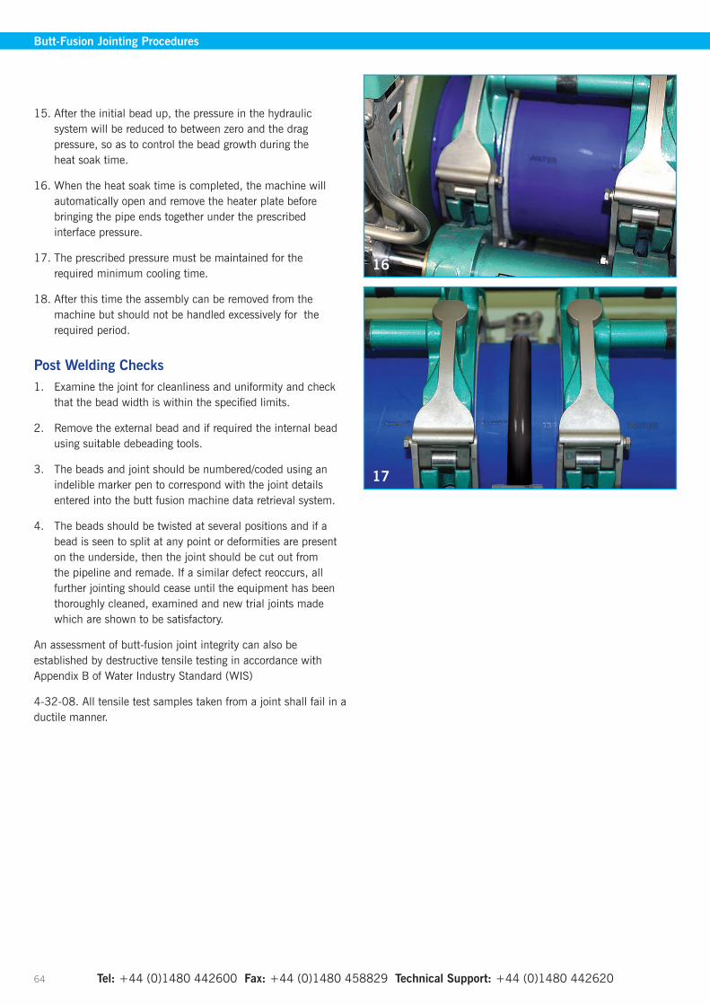
Tel: +44 (0)1480 442600 Fax: +44 (0)1480 458829 Technical Support: +44 (0)1480 442620 64
15. After the initial bead up, the pressure in the hydraulic system will be reduced to between zero and the drag pressure, so as to control the bead growth during the heat soak time.
16. When the heat soak time is completed, the machine will automatically open and remove the heater plate before bringing the pipe ends together under the prescribed interface pressure.
17. The prescribed pressure must be maintained for the required minimum cooling time.
18. After this time the assembly can be removed from the machine but should not be handled excessively for the required period.
Post Welding Checks1. Examine the joint for cleanliness and uniformity and check
that the bead width is within the specified limits.
2. Remove the external bead and if required the internal bead using suitable debeading tools.
3. The beads and joint should be numbered/coded using an indelible marker pen to correspond with the joint details entered into the butt fusion machine data retrieval system.
4. The beads should be twisted at several positions and if a bead is seen to split at any point or deformities are present on the underside, then the joint should be cut out from the pipeline and remade. If a similar defect reoccurs, all further jointing should cease until the equipment has been thoroughly cleaned, examined and new trial joints made which are shown to be satisfactory.
An assessment of butt-fusion joint integrity can also be established by destructive tensile testing in accordance with Appendix B of Water Industry Standard (WIS)
4-32-08. All tensile test samples taken from a joint shall fail in a ductile manner.
Butt-Fusion Jointing Procedures
16
17
Website: www.gpsuk.com Email: [email protected] 65
Butt-Fusion Jointing Procedures
Pre-Jointing Checks• Use equipment that is clean, in good condition and
regularly maintained.
• Ensure the correct jointing parameters for the machine type and pipe are known.
• Check that the heater plate is clean and dry.
• Check that the trimmer is clean and that the blades are not damaged and in the correct position for the required pipe size.
• Ensure clamp liners and securing screws are of the correct size.
• Ensure the generator is in good condition and has sufficient fuel.
Dos• DO WORK SAFELY
• Do understand the principals of butt fusion (refer to pipe manufacturers/machine suppliers guidelines if necessary).
• Do always input correct operator code and job code to allow for full traceability with Automatic Butt Fusion machines.
• Do mark finished joint with joint number.
• Do use a shelter and ground sheet (a suitable anti- slip surface*), both in dry and wet conditions, to minimise contamination, and fit end protection to pipes, (plugs or caps) to eliminate draughts.
• Do ensure pipes are aligned correctly and supported on pipe rollers to minimise drag.
• Do position pipes in clamps with pipe markings aligned and to the top.
• Do perform dummy welds at the start of every welding session, when changing pipe size or if the heater plate has been allowed to cool (one dummy weld on pipe size 180mm and below and two on larger pipe sizes).
• Do ensure that when trimming, a continuous ribbon of material is produced from both pipe ends before commencing feathering operation.
• Do always use trimmer and heater plate stands provided.
• Do always remove swarf from underneath pipe ends and machine chassis following trimming.
• Do visually check that both pipe ends are completely trimmed.
• Do always check pipes for alignment and gaps around the entire circumference of the abutted pipes.
• Do always remove external bead from completed joint, inspect for slit defects/bead uniformity then bag and label with corresponding joint number for full traceability.
Don’ts• Do not attempt to use equipment unless trained to do so.
• Do not attempt to weld pipes of different wall thickness.
• Do not touch trimmer blades when cleaning and especially when in motion, blades are very sharp and can cause serious injury.
• Do not touch heater plate (unless to clean when cold).
• Do not leave swarf inside pipe or on machine chassis.
• Do not introduce dirt onto trimmed pipe ends at any time, particularly when removing swarf.
• Do not remove pipes from machine until cooling time has elapsed.
• Do not attempt to install pipe until fully cooled.
• Do not attempt to operate the trimmer whilst it is out of the machine or attempt to by-pass the safety switch.
• Do not attempt to cut corners in any part of the welding cycle.
Health & SafetyGPS make every effort in the design and manufacture of their pipes and fittings to ensure safety in use. The following precautions are however worth bearing in mind:
• Never allow hot polyethylene to come into contact with the skin. In such an event cold water should be used to cool the affected area. Expert medical advice must be sought.
• Under no circumstances should any attempt be made to remove any material that becomes stuck on the skin without medical supervision, as this would risk more serious injury.
• Heavy pipes, fittings and equipment should not be handled without assistance or mechanical aid. The requirements of Manual Handling Operations Regulation 1992 should be adhered to.
• GPS recommend the wearing of Personal Protective Equipment in compliance with statutory legislation such as gloves, safety glasses and safety boots whilst carrying out butt-fusion.
• Care should be exercised by taking normal precautions when using electrical equipment on site, particularly in wet conditions.
• Normal precautions should be observed when handling electrical equipment. For safety reasons, all 110v portable generator sets should be ‘Centre Tapped’ for site use +55/0/-55 volts.
• Remember an audible alarm is fitted to automatic butt- fusion machines to warn of impending movement.
Always remember that where joint records are automatically stored, these should be downloaded on a regular basis to allow full traceability and integrity of workmanship.
Butt-Fusion Jointing Dos / Don’ts
* Consideration should be given to a firm level base such as 19mm Marine Ply which is our minimum recommendation.
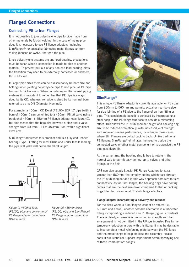
Tel: +44 (0)1480 442600 Fax: +44 (0)1480 458829 Technical Support: +44 (0)1480 442620 66
Connecting PE to Iron FlangesIt is not possible to join polyethylene pipe to pipe made from other materials by fusion welding. In the case of mains pipe sizes it is necessary to use PE flange adaptors, including SlimFlange®, or specialist fabricated metal fittings eg. from Viking Johnson or WASK, that grip the pipe.
Since polyethylene systems are end-load bearing, precautions must be taken when a connection is made to pipe of another material. To prevent pull-out of any non end-load bearing joints, the transition may need to be externally harnessed or anchored/thrust blocked.
In larger pipe sizes there can be a discrepancy (in bore size and bolting) when jointing polyethylene pipe to iron pipe, as PE pipe has much thicker walls. When considering multi-material piping systems it is important to remember that PE pipe is always sized by its OD, whereas iron pipe is sized by its nominal bore, referred to as its DN (Diameter Nominal).
For example, a 450mm OD Excel (PE100) SDR 17 pipe (with a bore of 400mm) can be jointed to a 450mm PN16 valve using a traditional 450mm x 450mm PE flange adaptor (see figure (i)). But this means that the bore size between a pipe and a valve changes from 400mm (PE) to 450mm (iron) with a significant extra cost.
SlimFlange® addresses this problem and is a fully end- loaded bearing (Type 1) fitting for most SDRs and under tensile loading, the pipe will yield well before the SlimFlange®.
SlimFlange®
This unique PE flange adaptor is currently available for PE sizes from 250mm to 560mm and permits actual or near bore-size-for-size jointing of a PE pipe to the flange of an iron fitting or pipe. This considerable benefit is achieved by incorporating a steel hoop in the PE flange stub face to provide a reinforcing effect. This allows the PE stub shoulder height and backing ring size to be reduced dramatically, with increased joint strength and improved sealing performance, including in those cases where SlimFlanges are bolted back to back. Unlike traditional PE flanges, SlimFlange® eliminates the need to upsize the connected valve or other metal component or to downsize the PE pipe (see figure ii).
At the same time, the backing ring is free to rotate in the normal way to permit easy bolting-up to valves and other fittings in the field.
GPS can also supply Special PE Flange Adaptors for sizes greater than 560mm, that employ bolting which pass through the PE stub shoulder and in this way approach bore-size-for-size connectivity. As for SlimFlanges, the backing rings have bolting circles that are the next size down compared to that of backing rings fitted to conventional PE stub flange adaptors.
Flange adaptor incorporating a polyethylene reducer
For the sizes where a SlimFlange® cannot be offered (ie. 630mm and above), another possible alternative is a fabricated fitting incorporating a reduced size PE flange (figure iii overleaf). There is clearly an associated reduction in strength and the arrangement is not permitted in the UK gas industry. Due to the temporary reduction in bore with this fitting, it may be desirable to incorporate a metal reinforcing plate between the PE flange and the metal flange to help stabilise the assembly. Please consult our Technical Support Department before specifying one of these ‘combination’ flanges.
Flanged Connections
Flanged Connections
Figure (i) 450mm Excel (PE100) pipe and conventional PE flange adaptor bolted to a DN450 valve.
Figure (ii) 450mm Excel (PE100) pipe and SlimFlange® PE flange adaptor bolted to a DN400 valve.
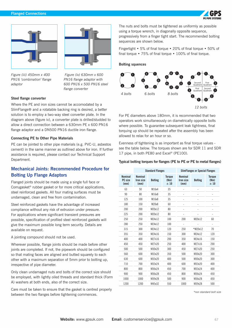
Website: www.gpsuk.com Email: [email protected] 67
Flanged Connections
Figure (iii) 450mm x 400 PN16 ‘combination’ flange adaptor
Figure (iv) 630mm x 600 PN16 flange adaptor with 600 PN16 x 500 PN16 steel flange converter
Steel flange converter
Where the PE and iron sizes cannot be accomodated by a SlimFlange® and a rotatable backing ring is desired, a better solution is to employ a two-way steel converter plate. In the diagram above (figure iv), a converter plate is drilled/studded to allow a direct connection between a 630mm PE x 600 PN16 flange adaptor and a DN500 PN16 ductile iron flange.
Connecting PE to Other Pipe Materials
PE can be jointed to other pipe materials (e.g. PVC-U, asbestos cement) in the same manner as outlined above for iron. If further assistance is required, please contact our Technical Support Department.
Mechanical Joints: Recommended Procedure for Bolting Up Flange AdaptorsFlanged joints should be made using a single full face or Corrugasket® rubber gasket or for more critical applications, steel reinforced gaskets. All four mating surfaces must be undamaged, clean and free from contamination.
Steel reinforced gaskets have the advantage of increased compliance without any risk of extrusion under pressure. For applications where significant transient pressures are possible, specification of profiled steel reinforced gaskets will give the maximum possible long term security. Details are available on request.
A jointing compound should not be used.
Wherever possible, flange joints should be made before other joints are completed. If not, the pipework should be configured so that mating faces are aligned and butted squarely to each other with a maximum separation of 5mm prior to bolting up, irrespective of pipe diameter.
Only clean undamaged nuts and bolts of the correct size should be employed, with lightly oiled threads and standard thick (Form A) washers at both ends, also of the correct size.
Care must be taken to ensure that the gasket is centred properly between the two flanges before tightening commences.
The nuts and bolts must be tightened as uniformly as possible using a torque wrench, in diagonally opposite sequence, progressively from a finger tight start. The recommended bolting sequences are shown below.
Fingertight • 5% of final torque • 20% of final torque • 50% of final torque • 75% of final torque • 100% of final torque.
Bolting squences
4 bolts 6 bolts 8 bolts
12 bolts
For PE diameters above 180mm, it is recommended that two operators work simultaneously on diametrically opposite bolts where possible. To guarantee subsequent leak tightness, final torquing up should be repeated after the assembly has been allowed to relax for an hour or so.
Evenness of tightening is as important as final torque values - see the table below. The torques shown are for SDR 11 and SDR 17 pipe, in both PE80 and Excel® (PE100).
Typical bolting torques for flanges (PE to PE or PE to metal flanges)
Standard Flanges SlimFlanges or Special Flanges
Nominal PE size (mm)
Nominal Iron size
(mm)Bolting
Torque (Nm) ± 10
Nominal Iron size
(mm)Bolting
Torque (Nm) ± 10
63 50 M16x4 35 - - -
90 80 M16x8 35 - - -
125 100 M16x8 35 - - -
180 150 M20x8 60 - - -
200 200 M20x12 80 - - -
225 200 M20x12 80 - - -
250 250 M24x12 100 200 M20x12 60
280 250 M24x12 100 - - -
315 300 M24x12 120 250 *M20x12 70
355 350 M24x16 150 300 M24x12 120
400 400 M27x16 200 350 M24x16 150
450 450 M27x20 250 400 M27x16 200
500 500 M30x20 300 450 M27x20 250
560 600 M33x20 350 500 M30x20 300
630 600 M33x20 400 500 M30x20 300
710 700 M33x24 400 600 M33x20 400
800 800 M36x24 450 700 M33x24 400
900 900 M36x28 450 800 M36x24 450
1000 1000 M39x28 500 900 M36x28 450
1200 1200 M45x32 550 1000 M39x28 500
*non standard bolt size

Tel: +44 (0)1480 442600 Fax: +44 (0)1480 458829 Technical Support: +44 (0)1480 442620 68
Repair Section Including Squeeze-Off
Repair Section Including Squeeze-Off
Where a repair is required remote from valves or where it would be too expensive to empty the pipe line, the flow of the contents in a polyethylene pipe can be arrested by using equipment that squeezes the pipe walls together.
This method was developed by the UK Gas Industry in the early 1980s. The squeeze-off equipment comprises of two tangential bars to apply pressure to the outside of the pipe. The bars are moved together, manually or hydraulically, squeezing the pipe material until a seal is formed where the upper and lower walls meet. Manual tools are used up to and including 90mm, with Hydraulic jacks used to provide the necessary force to compress the pipe wall for sizes 110mm and above. Hydraulic tools have a spring return for the jack and locking pins to prevent accidental release of pressure during operation.
Built in rotatable ‘check plates’ protect the pipe from damage from over compression. These plates can be exchanged to allow the tool to be used with the many sizes of metric and imperial pipe that exist.
Testing has shown that all types of polyethylene pipes can split during squeeze-off, if there is damage in the region of the pinch points, therefore prior to squeeze off it is absolutely essential that the pipe surfaces in the region of the pinch points are carefully inspected and are completely free of any surface damage before squeeze off commences.
Where the pipe wall is compressed the polyethylene pipe will be severely deformed in the regions of maximum compression. PE100 polyethylene material will also discolour due to stress whitening.
Following squeeze-off, the pipe will eventually regain its original shape after the release of the squeeze-off equipment, however re-rounding equipment is available to assist restoring pipe circularity. It is recommended not to force the pipe back to a round shape more quickly than necessary, especially in cold weather.
The following important points should be noted
• Specifically designed equipment fitted with the correct ‘check plates’ should be used to avoid over compression of the pipe.
For SDR 13.6 pipe the following check plates should be used: 63mm pipe – 55mm SDR 11 or 90mm SDR 17 stop
75mm pipe – 63mm SDR 11 stop
• The procedure must not be carried out within 3 pipe diameters of a fitting, a fusion joint or a previous squeeze-off operation.
• The squeeze-off procedure should not normally be used on pipes larger than 500mm diameter.
• The pipe surfaces in the region of the pinch points, should be carefully inspected for any damage prior to squeeze-off.
• Peelable pipes must also first have the skin removed as detailed above.
After the squeeze-off procedure is complete the pipe must be
• Inspected and re-rounded if necessary
• Renewed if there are any signs that the pipe is damaged ie splitting or cracking
• Recorded and marked as having been squeezed-off.
Tests which have been carried out by external test laboratories have indicated that satisfactory long-term performance can be achieved on previously squeezed-off and re-rounded pipes of various wall thicknesses.
Individual Utility Companies may limit the maximum diameter of pipe that can be squeezed-off and/or may require the use of stainless steel reinforcement bands above certain diameters.
Further details are given in the WRc Polyethlene Pipe Systems for Water Supply Manual.

Website: www.gpsuk.com Email: [email protected] 69
Repair Section Including Squeeze-Off
Repair Using ElectrofusionThe pipe stops incorporated in the Frialen couplers are shearable and have been provided for the specific purpose of using the fittings for making repairs or breaking into existing pipelines.
Standard PE Pipes RepairsThe procedure, shown diagrammatically in fig.1: is as follows:
1. Cut out the damaged section of pipe and ensure the pipe is cut square.
2. Measure the distance (L) between the exposed pipe ends and cut the pipe length to be inserted equal to the measured distance less 10mm.
3. Clean the pipe ends for a distance slightly greater than the overall length of the coupler.
4. Scrape the pipe ends, as previously described, but for the overall length of the coupler.
Note: The use of mechanical end preparation tools is preferred as hand scraping requires great care and can be time-consuming especially on larger diameter pipes. It is essential that material is removed by scraping or peeling: scratching or abrading is not sufficient.
5. Remove the pipe stops in the coupler. This can be most satisfactorily achieved by placing one end of a thoroughly cleaned short length of pipe into the coupler and striking the other end onto a hard surface. The pipe stops can also be removed using a sharp knife, but care must be taken not to damage the bore of the fitting.
6. Using a suitable marker pen, draw a mark on each end of the pipe to be inserted which will be used to indicate where the mouth of each socket of the coupler should be positioned prior to fusion.
7. Check the jointing areas are clean and dry, use isopropanol wipes if necessary.
8. Care should be taken to ensure any of the residual water in the mains is not allowed to come into contact with the electrofusion area. It may not be possible to maintain a clean dry area, in such cases the couplings should be mechanical.
9. Place the repair couplers over the exposed length of the installed main and slide these away from each other to allow the new pipe to be inserted between the exposed ends.
10. Insert the new pipe and align.
11. Slide the couplers towards each other as shown in the diagrams ensuring that the socket mouths line up with the marks on the pipe.
12. Carry out the normal jointing procedure as described in the previous section.
Figure 1.
Note: Stub Flange Assemblies may be used where there is a risk of water in the pipe contaminating joints during installation.

Tel: +44 (0)1480 442600 Fax: +44 (0)1480 458829 Technical Support: +44 (0)1480 442620 70
Duck Foot Bend Assembly
Assembly Instructions
1. Secure a concrete base into the ground and fit 4 x M16 bolts at 180 x 160mm centres. (Bolts not included in kit).
2. Fix and bolt the
Duck Foot Bend base piece to the concrete base. Note that the orientation of the base should be such that the incoming flow meets the face of the Duck Foot Bend base.
3. Remove the lower pipe stop from the electrofusion tee and push firmly onto the base. As for part 2, the orientation of the electrofusion equal tee should be such that the incoming flow meets the face of the Duck Foot Bend base.
Note: Ensure that the bare spigot has been adequately scraped.
4. Cut the length of the pupped stub flange as required.
Note: that the total height (h) should include the Fire Hydrant height. Scrape the stub flange pipe end and place in the top of the electrofusion tee. Electrofuse the tee, securing the base and stub into place.
5. Electrofuse the coupler, reducer or spigot reducer into place and electrofuse to the incoming pipe.
Note: Ensure that the bare spigot has been adequately scraped.
6. Connect the hydrant
to the stub flange assembly following the stub flange bolting procedure.
Duck Foot Bend Assembly
180 mm
160
mm
Flow out
Flow out
h
Flow in
Flow in Incoming pipe
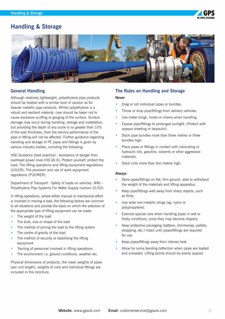
Website: www.gpsuk.com Email: [email protected] 71
Handling & Storage
General HandlingAlthough relatively lightweight, polyethylene pipe products should be treated with a similar level of caution as for heavier metallic pipe products. Whilst polyethylene is a robust and resilient material, care should be taken not to cause excessive scuffing or gouging of the surface. Surface damage may occur during handling, storage and installation, but providing the depth of any score is no greater than 10% of the wall thickness, then the service performance of the pipe or fitting will not be affected. Further guidance regarding handling and storage of PE pipes and fittings is given by various industry bodies, including the following:
HSE Guidance (best practice) - Avoidance of danger from overhead power lines (HS GS 6); Protect yourself, protect the load; The lifting operations and lifting equipment regulations (LOLER); The provision and use of work equipment regulations (PUEWER).
Department of Transport - Safety of loads on vehicles. WRc - Polyethylene Pipe Systems For Water Supply (version 01/02).
In lifting operations, where either manual or mechanical effort is involved in moving a load, the following factors are common to all situations and provide the basis on which the selection of the appropriate type of lifting equipment can be made:
• The weight of the load
• The bulk, size or shape of the load
• The method of joining the load to the lifting system
• The centre of gravity of the load
• The method of security or stabilising the lifting equipment
• Training of personnel involved in lifting operations
• The environment i.e. ground conditions, weather etc.
Physical dimensions of products, the mean weights of pipes (per unit length), weights of coils and individual fittings are included in this brochure.
The Rules on Handling and StorageNever
• Drag or roll individual pipes or bundles.
• Throw or drop pipe/fittings from delivery vehicles.
• Use metal slings, hooks or chains when handling.
• Expose pipe/fittings to prolonged sunlight. (Protect with opaque sheeting or tarpaulin).
• Stack pipe bundles more than three metres or three bundles high.
• Place pipes or fittings in contact with lubricating or hydraulic oils, gasoline, solvents or other aggressive materials.
• Stack coils more than two metres high.
Always
• Store pipes/fittings on flat, firm ground, able to withstand the weight of the materials and lifting apparatus.
• Keep pipe/fittings well away from sharp objects, such as flints.
• Use wide non-metallic slings (eg. nylon or polypropylene).
• Exercise special care when handling pipes in wet or frosty conditions, since they may become slippery.
• Keep protective packaging (battens, shrinkwrap, pallets, strapping, etc.) intact until pipes/fittings are required for use.
• Keep pipes/fittings away from intense heat.
• Allow for some bending deflection when pipes are loaded and unloaded. Lifting points should be evenly spaced.
Handling & Storage
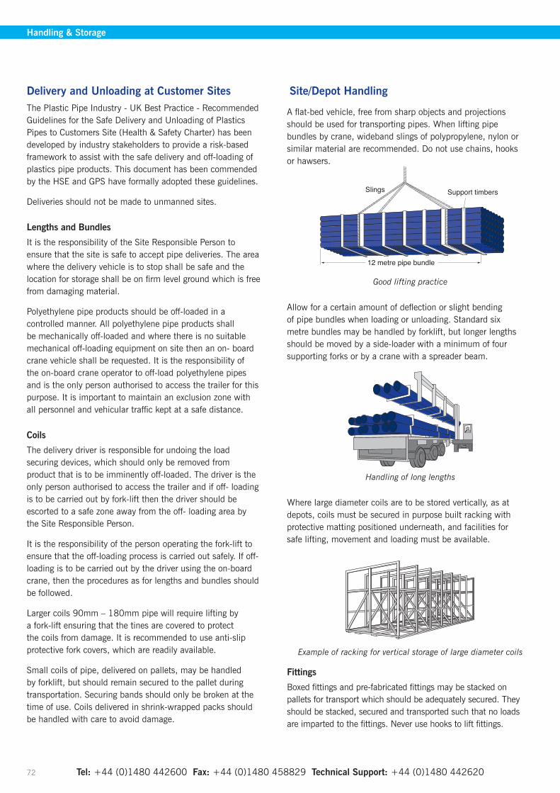
Tel: +44 (0)1480 442600 Fax: +44 (0)1480 458829 Technical Support: +44 (0)1480 442620 72
Handling & Storage
Delivery and Unloading at Customer SitesThe Plastic Pipe Industry - UK Best Practice - Recommended Guidelines for the Safe Delivery and Unloading of Plastics Pipes to Customers Site (Health & Safety Charter) has been developed by industry stakeholders to provide a risk-based framework to assist with the safe delivery and off-loading of plastics pipe products. This document has been commended by the HSE and GPS have formally adopted these guidelines.
Deliveries should not be made to unmanned sites.
Lengths and Bundles
It is the responsibility of the Site Responsible Person to ensure that the site is safe to accept pipe deliveries. The area where the delivery vehicle is to stop shall be safe and the location for storage shall be on firm level ground which is free from damaging material.
Polyethylene pipe products should be off-loaded in a controlled manner. All polyethylene pipe products shall be mechanically off-loaded and where there is no suitable mechanical off-loading equipment on site then an on- board crane vehicle shall be requested. It is the responsibility of the on-board crane operator to off-load polyethylene pipes and is the only person authorised to access the trailer for this purpose. It is important to maintain an exclusion zone with all personnel and vehicular traffic kept at a safe distance.
Coils
The delivery driver is responsible for undoing the load securing devices, which should only be removed from product that is to be imminently off-loaded. The driver is the only person authorised to access the trailer and if off- loading is to be carried out by fork-lift then the driver should be escorted to a safe zone away from the off- loading area by the Site Responsible Person.
It is the responsibility of the person operating the fork-lift to ensure that the off-loading process is carried out safely. If off-loading is to be carried out by the driver using the on-board crane, then the procedures as for lengths and bundles should be followed.
Larger coils 90mm – 180mm pipe will require lifting by a fork-lift ensuring that the tines are covered to protect the coils from damage. It is recommended to use anti-slip protective fork covers, which are readily available.
Small coils of pipe, delivered on pallets, may be handled by forklift, but should remain secured to the pallet during transportation. Securing bands should only be broken at the time of use. Coils delivered in shrink-wrapped packs should be handled with care to avoid damage.
Site/Depot Handling
A flat-bed vehicle, free from sharp objects and projections should be used for transporting pipes. When lifting pipe bundles by crane, wideband slings of polypropylene, nylon or similar material are recommended. Do not use chains, hooks or hawsers.
Good lifting practice
Allow for a certain amount of deflection or slight bending of pipe bundles when loading or unloading. Standard six metre bundles may be handled by forklift, but longer lengths should be moved by a side-loader with a minimum of four supporting forks or by a crane with a spreader beam.
Handling of long lengths
Where large diameter coils are to be stored vertically, as at depots, coils must be secured in purpose built racking with protective matting positioned underneath, and facilities for safe lifting, movement and loading must be available.
Example of racking for vertical storage of large diameter coils
Fittings
Boxed fittings and pre-fabricated fittings may be stacked on pallets for transport which should be adequately secured. They should be stacked, secured and transported such that no loads are imparted to the fittings. Never use hooks to lift fittings.
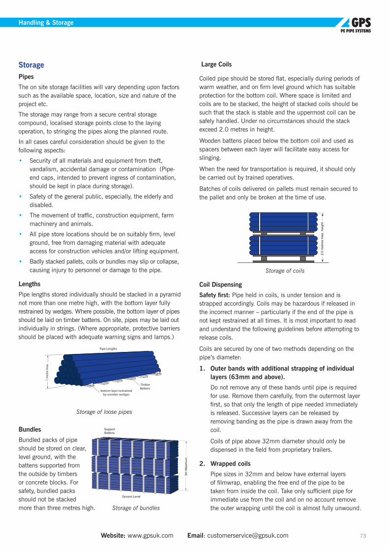
Website: www.gpsuk.com Email: [email protected] 73
Handling & Storage
StoragePipes
The on site storage facilities will vary depending upon factors such as the available space, location, size and nature of the project etc.
The storage may range from a secure central storage compound, localised storage points close to the laying operation, to stringing the pipes along the planned route.
In all cases careful consideration should be given to the following aspects:
• Security of all materials and equipment from theft, vandalism, accidental damage or contamination (Pipe- end caps, intended to prevent ingress of contamination, should be kept in place during storage).
• Safety of the general public, especially, the elderly and disabled.
• The movement of traffic, construction equipment, farm machinery and animals.
• All pipe store locations should be on suitably firm, level ground, free from damaging material with adequate access for construction vehicles and/or lifting equipment.
• Badly stacked pallets, coils or bundles may slip or collapse, causing injury to personnel or damage to the pipe.
Lengths
Pipe lengths stored individually should be stacked in a pyramid not more than one metre high, with the bottom layer fully restrained by wedges. Where possible, the bottom layer of pipes should be laid on timber battens. On site, pipes may be laid out individually in strings. (Where appropriate, protective barriers should be placed with adequate warning signs and lamps.)
Storage of loose pipes
Bundles
Bundled packs of pipe should be stored on clear, level ground, with the battens supported from the outside by timbers or concrete blocks. For safety, bundled packs should not be stacked more than three metres high. Storage of bundles
Large Coils
Coiled pipe should be stored flat, especially during periods of warm weather, and on firm level ground which has suitable protection for the bottom coil. Where space is limited and coils are to be stacked, the height of stacked coils should be such that the stack is stable and the uppermost coil can be safely handled. Under no circumstances should the stack exceed 2.0 metres in height.
Wooden battens placed below the bottom coil and used as spacers between each layer will facilitate easy access for slinging.
When the need for transportation is required, it should only be carried out by trained operatives.
Batches of coils delivered on pallets must remain secured to the pallet and only be broken at the time of use.
Storage of coils
Coil Dispensing
Safety first: Pipe held in coils, is under tension and is strapped accordingly. Coils may be hazardous if released in the incorrect manner – particularly if the end of the pipe is not kept restrained at all times. It is most important to read and understand the following guidelines before attempting to release coils.
Coils are secured by one of two methods depending on the pipe’s diameter:
1. Outer bands with additional strapping of individual layers (63mm and above).
Do not remove any of these bands until pipe is required for use. Remove them carefully, from the outermost layer first, so that only the length of pipe needed immediately is released. Successive layers can be released by removing banding as the pipe is drawn away from the coil.
Coils of pipe above 32mm diameter should only be dispensed in the field from proprietary trailers.
2. Wrapped coils
Pipe sizes in 32mm and below have external layers of filmwrap, enabling the free end of the pipe to be taken from inside the coil. Take only sufficient pipe for immediate use from the coil and on no account remove the outer wrapping until the coil is almost fully unwound.

Tel: +44 (0)1480 442600 Fax: +44 (0)1480 458829 Technical Support: +44 (0)1480 442620 74
Handling & Storage
Fittings
Electrofusion fittings should be stored under cover in dry conditions, preferably on racking. They should be kept in their boxes/packaging until ready for use. Fabricated fittings may be stored outdoors, as long as they are protected against damage and prolonged direct sunlight.
Storage OutsideBlack polyethylene material contains ultraviolet stabiliser to provide excellent protection against degradation due to UV radiation.
Blue and yellow polyethylene is UV stabilised to resist degradations in storage only. The maximum recommended storage outside, in Northern Europe, is 12 months. Product to be stored outside for periods in excess of this, should be covered with black polyethylene sheeting or stored under cover.
Additional precautions may be required, where polyethylene pipes are stored outside in regions of the world with high solar radiation.
Cutting PE PipesWhen using any pipe cutting equipment, care should be taken to follow the manufacturers instructions and to wear the appropriate protective clothing. Any statutory regulations regarding cutting equipment must be adhered to and operation only carried out by appropriately trained personnel.
Service pipe sizes
It is recommended that proprietary pipe secateurs are employed for service pipes, since these produce a smooth square end ready for electrofusion jointing or mechanical fitting assembly. When using pipe secateurs care should be taken to keep fingers and loose clothing clear of the cutting blade. After use, the secateurs should be closed and the catch engaged in order not to leave the blade exposed.
Mains pipe sizes
The following can be used for cutting PE mains pipes. In all cases blunt, warped or cracked saw blades should be replaced immediately:-
1. Coarse toothed hand-saws can be used at quite large pipe sizes, and proprietary guides are available which are designed to fit onto electrofusion alignment clamps.
2. Guillotine cutters and motorised pipe cutters are available from specialist tool hire companies.
3. Jigsaws fitted with coarse toothed blades are a readily
available option, however it is usually necessary to start from a suitably sized pre-drilled hole.
4. Alligator saws, which have reciprocating blades are a popular choice for cutting large PE pipes.
Specialist blades have been developed for use with petrol cut-off saws; however, operation and maintenance should only be undertaken by appropriately trained personnel.
When using any electrical equipment, the manufacturers’ mechanical and electrical safety instructions should be adhered to.
Chainsaws should not be used to cut PE pipes, irrespective of the machine type and saw tooth pattern. There is a significant risk of snagging/snatching occurring with these saws and it is also probable that lubricating oil would find its way onto the pipe surface, impeding any subsequent fusion jointing.
Whatever cutting tool is employed, the pipe to be cut should be adequately held and supported.
Any swarf produced by cutting, should be disposed of safely and with environmental consideration.

Website: www.gpsuk.com Email: [email protected] 75
Procedures & Techniques for PE Pipeline Installations
Polyethylene pipe systems from GPS are designed to make installation quicker, easier and more cost effective. Installation is as much a part of the costing equation as ease of maintenance and the cost of the pipe system itself. PE’s great advantage in installation is its lightness and flexibility, coupled with its durability and totally secure jointing methods. For all modern pipe laying techniques, whether in rehabilitation work or the construction of new pipelines above or below ground level, PE80 (MDPE) and Excel (PE100) systems from GPS usually provide the simplest, most economic solution. Indeed, rehabilitation techniques have been developed which rely completely on polyethylene’s unique properties.
A major advantage of PE is that pipe lengths can be butt- fused or electrofusion jointed to form a continuous string of pipe and there is rarely need for thrust blocks. This, together with the material’s inherent flexibility, (see material properties section for bend radii on page 8) makes polyethylene ideally suited to a full range of new and innovative installation techniques. GPS PE Pipe Systems support all methods of installation used today including chain trenching, mole ploughing, size-for-size moling, pipe bursting and slip-lining. Working practice and techniques for installing GPS products by a variety of pipe laying methods are as follows.
Low-Dig and No Dig New Lay Techniques for Buried Pipelines
Chain trenching
As previously noted, a major installation advantage of PE pipe is that lengths can be fused together by butt-fusion to form continuous strings. Since the need for in-trench jointing is virtually eliminated, the width of excavations can be minimised, resulting in reduced labour cost, less imported backfill and lower reinstatement costs. Modified mechanical diggers with oblique profiled buckets are ideal provided that the soil produced by the digging action is relatively fine. Chain excavators in particular will break up the original ground finely and permit trench widths only 50 to 100mm greater than the PE pipe outside diameter.
Profiled digger bucket
Procedures & Techniques for PE Pipeline Installations

Tel: +44 (0)1480 442600 Fax: +44 (0)1480 458829 Technical Support: +44 (0)1480 442620 76
Procedures & Techniques for PE Pipeline Installations
Moleploughing
This technique was originally developed for laying land drainage and adapted for installation of gas and water pipes in rural areas. It enables pipelines to be laid across rural landscapes with minimum disruption to agriculture, while the ground can also be reinstated virtually to prime condition. A new PE pipe string is literally ploughed into the ground to a prescribed depth and the ground restored immediately to its original condition.
Moleploughing
Impact moling
Impact moling is highly economic in instances such as road crossings, where considerable savings can be made over traditional open-cut excavation methods. Traffic control systems are often unnecessary, for example, and the cost of excavation, backfill and reinstatement is virtually eliminated. With this installation method, excavation is only necessary at the starting and finishing locations of the pipeline - in order to accommodate the mole and its ancillary equipment. The impact mole drives a borehole between launch and reception pits, leaving the ground surface undisturbed.
Impact moling (courtesy of TT-UK Ltd.)
Directional drilling
This is a pipe installation technique that was originally developed for oil and gas wells, however it is now increasingly used for PE pipe. It allows pipelines to be installed under roads and rivers etc. with minimal excavation work. The technique involves drilling a hole under an obstacle and then pulling the pipeline back through an enlarged hole from the far side. Tensile loading measuring devices, fitted to the pipe which is to be installed, are available to ensure that the pipe is not overstressed when directional drilling or pipe cracking is carried out.
The stages are as follows:
i) A small diameter ‘pilot hole’ is drilled from one side of the
obstacle to the next by a drill head attached to the ‘pilot string’ which, in turn, may be connected to a ‘washover’ pipe which overdrills the hole and provides rigidity to the pilot string.
ii) An enlarged hole is bored by one of various means, which include high-pressure fluid jets for cutting (plus carbide cutting blades to cope with the more difficult soils), and drill bits which are driven by mud motors.
iii) The drill head is steered by using a flexible joint close to the head which is moved by manipulation of the jets or by thrust force on the end of the drill string. A transmitter in the head sends signals to the surface, and these are received by a hand-held locator which displays both the lateral position and depth of the head, allowing tracing and guidance of the drill head.
iv) When the drill head exits on the far side of the obstacle, the drill head is removed and a reverse barrel reamer is attached to the washover pipe followed by the PE pipe string. The reamer is used to increase the size of the hole to the final size required to enable the PE pipe string to be pulled back through.
In the case of large diameter pipes, a number of passes are made using reamers of progressively increasing sizes before the final pull-through of the PE pipe string is carried out.

Website: www.gpsuk.com Email: [email protected] 77
Procedures & Techniques for PE Pipeline Installations
Rehabilitation and Renovation using No-Dig Techniques
Slip-lining / Insertion
In slip-lining or insertion, a replacement PE pipe string of smaller size is inserted into an existing decommissioned pipeline.
Although rarely necessary, pressure grouting (see page XX) of the annular gap can enable the existing pipeline to be rehabilitated structurally, whilst also reinforcing the hoop strength of the new PE pipe.
Though some reduction in flow capacity is inevitable, this can be minimised by careful preparation and cleaning of the old pipe so that the largest possible diameter of new PE pipe can be inserted. In many instances an average annular clearance of as little as five per cent of mains diameter - less still for sizes above 300mm - has proven adequate where pipelines are reasonably straight and of uniform bore. In pressure pipelines the reduction in carrying capacity can also be compensated for by an increase in internal pressure. In gravity applications any effect of bore reduction is minimised both by the exclusion of ground water entering the system and by the improved flow characteristics of PE.
Slip-lining

Tel: +44 (0)1480 442600 Fax: +44 (0)1480 458829 Technical Support: +44 (0)1480 442620 78
Procedures & Techniques for PE Pipeline Installations
Pipe burstingSize-for-size replacement or upsizing of existing iron pipelines can be achieved with significant savings by the pipe bursting method. With this technique an existing main is cracked open and the borehole simultaneously expanded by a mole. Modern pipe bursting moles - especially those with hydraulically expanding segments - can crack and open out an unserviceable pipeline, even if it has repair collars or concrete surrounds. Risk of damage to adjacent utility installations is minimised by using hydraulic moles, helping to maximise the cost advantages of using the existing ‘hole in the ground’. The early practice was to use a sacrificial polyethylene sleeve which was drawn behind the mole and into the cleared borehole through which the new PE main could be inserted. Naturally the use of a sacrificial PE sleeve or liner increased both time and cost of the operation, but nowadays with suitable pipe bursting equipment and in favourable ground conditions, a standard PE pipe can be installed directly behind mole, saving time as no second insertion is to take place.
Pipe bursting (courtesy of TT-UK Ltd.)
Pipe bursting in progress
Bursting head
Exit of bursting head from service trenchOriginal pipe in service trench
New pipe pulled into positionEntry of bursting head to service trench
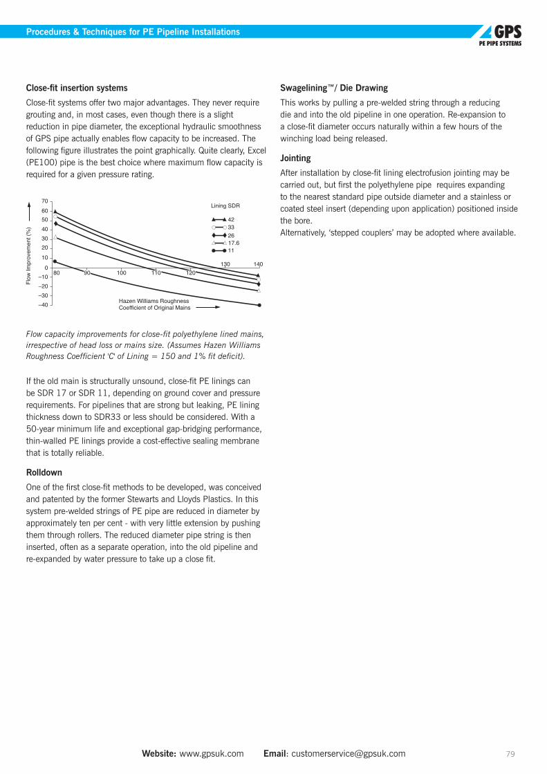
Website: www.gpsuk.com Email: [email protected] 79
Procedures & Techniques for PE Pipeline Installations
Close-fit insertion systems
Close-fit systems offer two major advantages. They never require grouting and, in most cases, even though there is a slight reduction in pipe diameter, the exceptional hydraulic smoothness of GPS pipe actually enables flow capacity to be increased. The following figure illustrates the point graphically. Quite clearly, Excel (PE100) pipe is the best choice where maximum flow capacity is required for a given pressure rating.
Flow capacity improvements for close-fit polyethylene lined mains, irrespective of head loss or mains size. (Assumes Hazen Williams Roughness Coefficient 'C' of Lining = 150 and 1% fit deficit).
If the old main is structurally unsound, close-fit PE linings can be SDR 17 or SDR 11, depending on ground cover and pressure requirements. For pipelines that are strong but leaking, PE lining thickness down to SDR33 or less should be considered. With a 50-year minimum life and exceptional gap-bridging performance, thin-walled PE linings provide a cost-effective sealing membrane that is totally reliable.
Rolldown
One of the first close-fit methods to be developed, was conceived and patented by the former Stewarts and Lloyds Plastics. In this system pre-welded strings of PE pipe are reduced in diameter by approximately ten per cent - with very little extension by pushing them through rollers. The reduced diameter pipe string is then inserted, often as a separate operation, into the old pipeline and re-expanded by water pressure to take up a close fit.
Swagelining™/ Die Drawing
This works by pulling a pre-welded string through a reducing die and into the old pipeline in one operation. Re-expansion to a close-fit diameter occurs naturally within a few hours of the winching load being released.
Jointing
After installation by close-fit lining electrofusion jointing may be carried out, but first the polyethylene pipe requires expanding to the nearest standard pipe outside diameter and a stainless or coated steel insert (depending upon application) positioned inside the bore. Alternatively, ‘stepped couplers’ may be adopted where available.
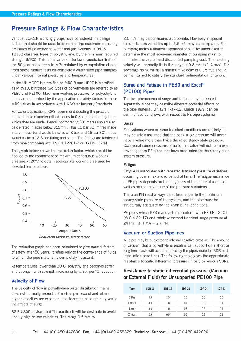
Tel: +44 (0)1480 442600 Fax: +44 (0)1480 458829 Technical Support: +44 (0)1480 442620 80
Pressure Ratings & Flow Characteristics
Various ISO/CEN working groups have considered the design factors that should be used to determine the maximum operating pressures of polyethylene water and gas systems. ISO/DIS 12162 classifies types of polyethylene, by the minimum required strength (MRS). This is the value of the lower prediction limit of the 50 year hoop stress in MPa obtained by extrapolation of data from stress rupture tests on completely water filled pipe samples under various internal pressures and temperatures.
In the UK MDPE is classified as MRS 8 and HPPE is classified as MRS10, but these two types of polyethylene are referred to as PE80 and PE100. Maximum working pressures for polyethylene pipes are determined by the application of safety factors to these MRS values in accordance with UK Water Industry Standards.
For water applications, GPS recommend derating the pressure rating of large diameter mitred bends to 0.8 x the pipe rating from which they are made. Bends incorporating 30° mitres should also be de-rated in sizes below 355mm. Thus 10 bar 30° mitres made into a mitred bend would be rated at 8 bar, and 16 bar 30° mitres would make a 12.8 bar fitting and so on. The fittings are fabricated from pipe complying with BS EN 12201-2 or BS EN 13244.
The graph below shows the reduction factor, which should be applied to the recommended maximum continuous working pressure at 20ºC to obtain appropriate working pressures for elevated temperatures.
Reduction factor vs Temperature
The reduction graph has been calculated to give normal factors of safety after 50 years. It refers only to the conveyance of fluids to which the pipe material is completely resistant.
At temperatures lower than 20ºC, polyethylene becomes stiffer and stronger, with strength increasing by 1.3% per ºC reduction.
Velocity of FlowThe velocity of flow in polyethylene water distribution mains, does not normally exceed 1-2 metres per second and where higher velocities are expected, consideration needs to be given to the effects of surge.
BS EN 805 advises that “in practice it will be desirable to avoid unduly high or low velocities. The range 0.5 m/s to
2.0 m/s may be considered appropriate. However, in special circumstances velocities up to 3.5 m/s may be acceptable. For pumping mains a financial appraisal should be undertaken to determine the most economic diameter of pumping main to minimise the capital and discounted pumping cost. The resulting velocity will normally lie in the range of 0.8 m/s to 1.4 m/s”. For sewerage rising mains, a minimum velocity of 0.75 m/s should be maintained to satisfy the standard sedimentation criterion.
Surge and Fatigue in PE80 and Excel®
(PE100) PipesThe two phenomena of surge and fatigue may be treated separately, since they describe different potential effects on the pipe material. UK IGN 4-37-02, March 1999, can be summarised as follows with respect to PE pipe systems:
Surge
For systems where extreme transient conditions are unlikely, it may be safely assumed that the peak surge pressure will never have a value more than twice the rated steady state pressure. Occasional surge pressures of up to this value will not harm even low toughness PE pipes that have been rated for the steady state system pressure.
Fatigue
Fatigue is associated with repeated transient pressure variations occurring over an extended period of time. The fatigue resistance of PE pipes depends on the toughness of the material used, as well as on the magnitude of the pressure variations.
The pipe PN must always be at least equal to the maximum steady state pressure of the system, and the pipe must be structurally adequate for the given burial conditions.
PE pipes which GPS manufactures conform with BS EN 12201 (WIS 4-32-17) and safely withstand transient surge pressure of 24 PN, i.e. PMA = 2 x PN.
Vacuum or Suction PipelinesAll pipes may be subjected to internal negative pressure. The amount of vacuum that a polyethylene pipeline can support on a short or long term basis will be determined by the pipe's material, SDR and installation conditions. The following table gives the approximate resistance to static differential pressure (in bar) by various SDRs.
Resistance to static differential pressure (Vacuum or External Fluid) for Unsupported PE100 Pipe
Term SDR 11 SDR 17 SDR 21 SDR 26 SDR 33
1 Day 5.9 1.9 1.1 0.5 0.3
1 Month 4.4 1.0 0.8 0.3 0.1
1 Year 3.3 1.0 0.5 0.3 0.1
50 Years 2.9 0.9 0.5 0.3 0.1
Pressure Ratings & Flow Characteristics
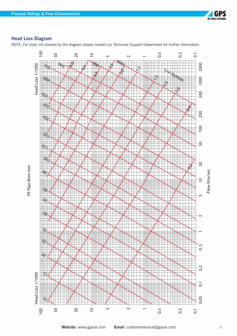
Website: www.gpsuk.com Email: [email protected] 81
Pressure Ratings & Flow Characteristics
Head Loss DiagramNOTE: For sizes not covered by the diagram please contact our Technical Support Department for further information.

Tel: +44 (0)1480 442600 Fax: +44 (0)1480 458829 Technical Support: +44 (0)1480 442620 82
Pressure Testing
Pipe Pressure testing should be according to BS EN 805 or IGN 4-01-03, “Pressure testing of pressure pipes and fittings for use by public water suppliers”.
CommissioningThe commissioning of new or repaired supply and distribution mains is normally carried out in the following sequence:
• Cleaning and/or swabbing of the main
• Filling and sterilisation
• Flushing and/or neutralisation
• Refilling the main
• Bacteriological sampling
• Acceptance certification
• Introduction and/or returning of the main into service
The sequence for PE should include these basic procedures but may be adapted to meet particular conditions (eg. pre-chlorination of sliplined mains). In all cases the procedures must comply with the requirement of the local Water Undertaking.
Service pipes should be tested with the ferrule connected to the main but before the cutter taps into the main.
After being tested, all service pipes must be subjected to a final disinfection process before being introduced into the water supply system. Guidance is given in the Water UK publication, “Principles of water supply hygiene and technical guidance notes”. The water utility should be consulted with regard to their disinfection policy for service connections.
Special attention should be paid to the proper sterilisation of those services laid to hospitals and renaldialysis machines.
For further support concerning specific installations, please contact our Technical Support Department.
Pressure Testing
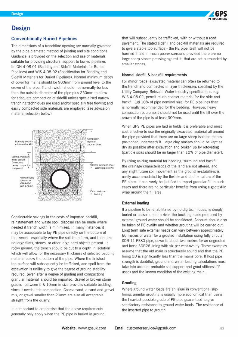
Website: www.gpsuk.com Email: [email protected] 83
Design
Conventionally Buried PipelinesThe dimensions of a trenchline opening are normally governed by the pipe diameter, method of jointing and site conditions. Guidance is provided on the selection and use of materials suitable for providing structural support to buried pipelines in IGN 4-08-01 (Bedding and Sidefill Materials for Buried Pipelines) and WIS 4-08-02 (Specification for Bedding and Sidefill Materials for Buried Pipelines). Normal minimum depth of cover for mains should be 900mm from ground level to the crown of the pipe. Trench width should not normally be less than the outside diameter of the pipe plus 250mm to allow for adequate compaction of sidefill unless specialised narrow trenching techniques are used and/or specially free flowing and easily compacted side materials are employed (see advice on material selection below).
Considerable savings in the costs of imported backfill, reinstatement and waste spoil disposal can be made where needed if trench width is minimised. In many instances it may be acceptable to lay PE pipe directly on the bottom of the trench - especially where the soil is uniform, and there are no large flints, stones, or other large hard objects present. In rocky ground, the trench should be cut to a depth in isolation which will allow for the necessary thickness of selected bedding material below the bottom of the pipe. Where the finished top surface will subsequently be trafficked, and spoil from the excavation is unlikely to give the degree of ground stability required, (even after a degree of grading and compaction) granular material should be imported. Gravel or broken stone graded between 5 & 10mm in size provides suitable bedding, since it needs little compaction. Coarse sand, a sand and gravel mix, or gravel smaller than 20mm are also all acceptable straight from the quarry.
It is important to emphasise that the above requirements generally only apply when the PE pipe is buried in ground
that will subsequently be trafficked, with or without a road pavement. The stated sidefill and backfill materials are required to give a stable top surface - the PE pipe itself will not be harmed if laid in much poorer surround provided there are no large sharp stones pressing against it, that are not surrounded by smaller stones.
Normal sidefill & backfill requirements
For minor roads, excavated material can often be returned to the trench and compacted in layer thicknesses specified by the Utility Company. Relevant Water Industry specifications. e.g. WIS 4-08-02, permit much coarser material for the side and backfill (uti 10% of pipe nominal size) for PE pipelines than is normally recommended for the bedding. However, heavy compaction equipment should not be used until the fill over the crown of the pipe is at least 300mm.
When GPS PE pipes are laid in fields it is preferable and most cost effective to use the originally excavated material all around the pipe provided that there are no large sharp isolated stones positioned underneath it. Large clay masses should be kept as dry as possible after excavation and broken up by rotovating (particle sizes should be no larger than 10% of pipe diameter).
By using as-dug material for bedding, surround and backfill, the drainage characteristics of the land are not altered, and any slight future soil movement as the ground re-stabilises is easily accommodated by the flexible and ductile nature of the PE pipes. It can rarely be justified to import granular fill in such cases and there are no particular benefits from using a geotextile wrap around the fill area.
External loading
If a pipeline to be rehabilitated by no-dig techniques, is deeply buried or passes under a river, the buckling loads produced by external ground water should be considered. Account should also be taken of PE ovality and whether grouting will be carried out. Long term safe external heads can vary between approximately 60 metres of water for a grouted installation using fully circular SDR 11 PE80 pipe, down to about two metres for an ungrouted and loose SDR26 lining with six per cent ovality. These examples assume that the old main is structurally sound and that the PE lining OD is significantly less than the mains bore. If host pipe strength is doubtful, ground and water loading calculations must take into account probable soil support and grout stiffness (if used) and the known condition of the existing main.
Grouting
Where ground water loads are an issue in conventional slip-lining, annular grouting is usually more economical than using the heaviest possible grade of PE pipe guaranteed to give satisfactory resistance to ground water loads. The resistance of the inserted pipe to groutin
Design
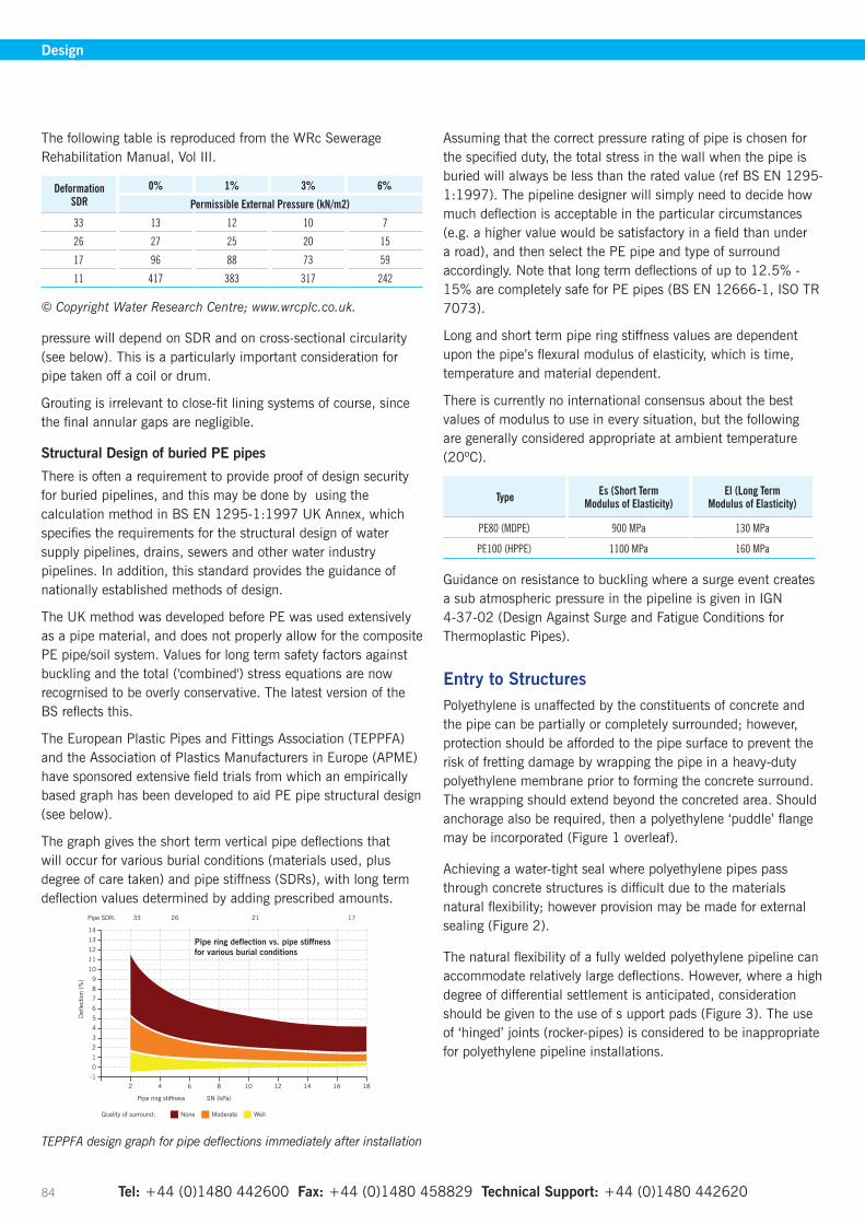
Tel: +44 (0)1480 442600 Fax: +44 (0)1480 458829 Technical Support: +44 (0)1480 442620 84
Design
The following table is reproduced from the WRc Sewerage Rehabilitation Manual, Vol III.
DeformationSDR
0% 1% 3% 6%
Permissible External Pressure (kN/m2)
33 13 12 10 7
26 27 25 20 15
17 96 88 73 59
11 417 383 317 242
© Copyright Water Research Centre; www.wrcplc.co.uk.
pressure will depend on SDR and on cross-sectional circularity (see below). This is a particularly important consideration for pipe taken off a coil or drum.
Grouting is irrelevant to close-fit lining systems of course, since the final annular gaps are negligible.
Structural Design of buried PE pipes
There is often a requirement to provide proof of design security for buried pipelines, and this may be done by using the calculation method in BS EN 1295-1:1997 UK Annex, which specifies the requirements for the structural design of water supply pipelines, drains, sewers and other water industry pipelines. In addition, this standard provides the guidance of nationally established methods of design.
The UK method was developed before PE was used extensively as a pipe material, and does not properly allow for the composite PE pipe/soil system. Values for long term safety factors against buckling and the total ('combined') stress equations are now recogrnised to be overly conservative. The latest version of the BS reflects this.
The European Plastic Pipes and Fittings Association (TEPPFA) and the Association of Plastics Manufacturers in Europe (APME) have sponsored extensive field trials from which an empirically based graph has been developed to aid PE pipe structural design (see below).
The graph gives the short term vertical pipe deflections that will occur for various burial conditions (materials used, plus degree of care taken) and pipe stiffness (SDRs), with long term deflection values determined by adding prescribed amounts.
TEPPFA design graph for pipe deflections immediately after installation
Assuming that the correct pressure rating of pipe is chosen for the specified duty, the total stress in the wall when the pipe is buried will always be less than the rated value (ref BS EN 1295-1:1997). The pipeline designer will simply need to decide how much deflection is acceptable in the particular circumstances (e.g. a higher value would be satisfactory in a field than under a road), and then select the PE pipe and type of surround accordingly. Note that long term deflections of up to 12.5% - 15% are completely safe for PE pipes (BS EN 12666-1, ISO TR 7073).
Long and short term pipe ring stiffness values are dependent upon the pipe’s flexural modulus of elasticity, which is time, temperature and material dependent.
There is currently no international consensus about the best values of modulus to use in every situation, but the following are generally considered appropriate at ambient temperature (20ºC).
Type Es (Short TermModulus of Elasticity)
El (Long TermModulus of Elasticity)
PE80 (MDPE) 900 MPa 130 MPa
PE100 (HPPE) 1100 MPa 160 MPa
Guidance on resistance to buckling where a surge event creates a sub atmospheric pressure in the pipeline is given in IGN 4-37-02 (Design Against Surge and Fatigue Conditions for Thermoplastic Pipes).
Entry to StructuresPolyethylene is unaffected by the constituents of concrete and the pipe can be partially or completely surrounded; however, protection should be afforded to the pipe surface to prevent the risk of fretting damage by wrapping the pipe in a heavy-duty polyethylene membrane prior to forming the concrete surround. The wrapping should extend beyond the concreted area. Should anchorage also be required, then a polyethylene ‘puddle’ flange may be incorporated (Figure 1 overleaf).
Achieving a water-tight seal where polyethylene pipes pass through concrete structures is difficult due to the materials natural flexibility; however provision may be made for external sealing (Figure 2).
The natural flexibility of a fully welded polyethylene pipeline can accommodate relatively large deflections. However, where a high degree of differential settlement is anticipated, consideration should be given to the use of s upport pads (Figure 3). The use of ‘hinged’ joints (rocker-pipes) is considered to be inappropriate for polyethylene pipeline installations.
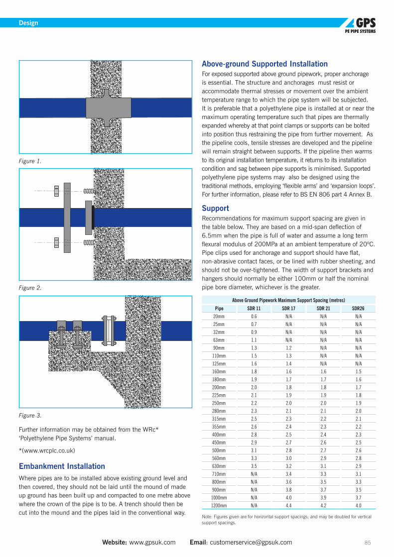
Tel: +44 (0)1480 442600 Fax: +44 (0)1480 458829 Technical Support: +44 (0)1480 442620 Website: www.gpsuk.com Email: [email protected] 85
Design
Figure 1.
Figure 2.
Figure 3.
Further information may be obtained from the WRc* ‘Polyethylene Pipe Systems’ manual.
*(www.wrcplc.co.uk)
Embankment InstallationWhere pipes are to be installed above existing ground level and then covered, they should not be laid until the mound of made up ground has been built up and compacted to one metre above where the crown of the pipe is to be. A trench should then be cut into the mound and the pipes laid in the conventional way.
Above-ground Supported InstallationFor exposed supported above ground pipework, proper anchorage is essential. The structure and anchorages must resist or accommodate thermal stresses or movement over the ambient temperature range to which the pipe system will be subjected. It is preferable that a polyethylene pipe is installed at or near the maximum operating temperature such that pipes are thermally expanded whereby at that point clamps or supports can be bolted into position thus restraining the pipe from further movement. As the pipeline cools, tensile stresses are developed and the pipeline will remain straight between supports. If the pipeline then warms to its original installation temperature, it returns to its installation condition and sag between pipe supports is minimised. Supported polyethylene pipe systems may also be designed using the traditional methods, employing ‘flexible arms’ and ‘expansion loops’. For further information, please refer to BS EN 806 part 4 Annex B.
SupportRecommendations for maximum support spacing are given in the table below. They are based on a mid-span deflection of 6.5mm when the pipe is full of water and assume a long term flexural modulus of 200MPa at an ambient temperature of 20ºC. Pipe clips used for anchorage and support should have flat, non-abrasive contact faces, or be lined with rubber sheeting, and should not be over-tightened. The width of support brackets and hangers should normally be either 100mm or half the nominal pipe bore diameter, whichever is the greater.
Above Ground Pipework Maximum Support Spacing (metres)
Pipe SDR 11 SDR 17 SDR 21 SDR2620mm 0.6 N/A N/A N/A25mm 0.7 N/A N/A N/A32mm 0.9 N/A N/A N/A63mm 1.1 N/A N/A N/A90mm 1.3 1.2 N/A N/A
110mm 1.5 1.3 N/A N/A125mm 1.6 1.4 N/A N/A160mm 1.8 1.6 1.6 1.5180mm 1.9 1.7 1.7 1.6200mm 2.0 1.8 1.8 1.7225mm 2.1 1.9 1.9 1.8250mm 2.2 2.0 2.0 1.9280mm 2.3 2.1 2.1 2.0315mm 2.5 2.3 2.2 2.1355mm 2.6 2.4 2.3 2.2400mm 2.8 2.5 2.4 2.3450mm 2.9 2.7 2.6 2.5500mm 3.1 2.8 2.7 2.6560mm 3.3 3.0 2.9 2.8630mm 3.5 3.2 3.1 2.9710mm N/A 3.4 3.3 3.1800mm N/A 3.6 3.5 3.3900mm N/A 3.8 3.7 3.5
1000mm N/A 4.0 3.9 3.71200mm N/A 4.4 4.2 4.0
Note: Figures given are for horizontal support spacings; and may be doubled for vertical support spacings.
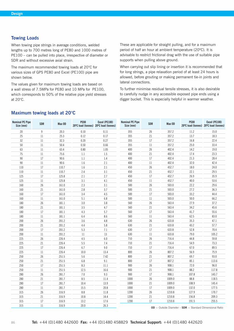
Tel: +44 (0)1480 442600 Fax: +44 (0)1480 458829 Technical Support: +44 (0)1480 442620 86
Design
Towing LoadsWhen towing pipe strings in average conditions, welded lengths up to 700 metres long of PE80 and 1000 metres of PE100 – can be pulled into place, irrespective of diameter or SDR and without excessive axial strain.
The maximum recommended towing loads at 20°C for various sizes of GPS PE80 and Excel (PE100) pipe are shown below.
The values given for maximum towing loads are based on a wall stress of 7.5MPa for PE80 and 10 MPa for PE100, which corresponds to 50% of the relative pipe yield stresses at 20°C.
These are applicable for straight pulling, and for a maximum period of half an hour at ambient temperature (20ºC). It is advisable to restrict frictional drag with the use of suitable pipe supports when pulling above ground.
When carrying out slip lining or insertion it is recommended that for long strings, a pipe relaxation period of at least 24 hours is allowed, before grouting or making permanent tie-in joints and lateral connections.
To further minimise residual tensile stresses, it is also desirable to carefully nudge in any accessible exposed pipe ends using a digger bucket. This is especially helpful in warmer weather.
Maximum towing loads at 20°C
Nominal PE Pipe Size (mm) SDR Max OD PE80
20ºC load (tonnes)Excel (PE100)
20ºC load (tonnes)
20 9 20.3 0.10 0.1125 11 25.3 0.12 0.1732 11 32.3 0.20 0.2750 11 50.4 0.50 0.6663 11 63.4 0.80 1.0575 11 75.6 1.1 1.590 17 90.6 1.1 1.490 11 90.6 1.6 2.1
110 17 110.7 1.6 2.1110 11 110.7 2.4 3.1125 17 125.8 2.1 2.7125 11 125.8 3.1 4.1160 26 161.0 2.3 3.1160 21 161.0 2.8 3.7160 17 161.0 3.4 4.5160 11 161.0 5.1 6.8180 26 181.1 3.0 3.8180 21 181.1 3.5 4.7180 17 181.1 4.3 5.7180 11 181.1 6.4 8.6200 26 201.2 3.6 4.8200 21 201.2 4.4 5.8200 17 201.2 5.3 7.1200 11 201.2 11 13225 26 226.4 4.5 6.0225 21 226.4 5.5 7.4225 17 226.4 6.7 9.0225 11 226.4 10.0 13.4250 26 251.5 5.6 7.42250 21 251.5 6.8 9.1250 17 251.5 8.3 11.1250 11 251.5 12.5 16.6280 26 281.7 7.0 9.3280 21 281.7 8.5 11.4280 17 281.7 10.4 13.9280 11 281.7 15.5 20.8315 26 316.9 8.8 11.8315 21 316.9 10.8 14.4315 17 316.9 13.2 17.6315 11 316.9 20.0 26.3
Nominal PE Pipe Size (mm) SDR Max OD PE80
20ºC load (tonnes)Excel (PE100)
20ºC load (tonnes)
355 26 357.2 11.2 15.0355 21 357.2 13.7 18.3355 17 357.2 16.8 22.4355 11 357.2 25.0 33.4400 26 402.4 14.2 19.0400 21 402.4 17.4 23.3400 17 402.4 21.3 28.4400 11 402.4 32.0 42.4450 26 452.7 18.0 24.0450 21 452.7 22.1 29.5450 17 452.7 26.9 35.9450 11 452.7 40.0 53.6500 26 503.0 22.2 29.6500 21 503.0 27.2 36.3500 17 503.0 33.2 44.4500 11 503.0 50.0 66.2560 26 563.4 27.9 37.2560 21 563.4 34.2 45.6560 17 563.4 41.7 55.6560 11 563.4 62.5 83.0630 26 633.8 35.3 47.1630 21 633.8 43.2 57.7630 17 633.8 52.8 70.4630 11 633.8 79.0 105.2710 26 716.4 44.8 59.8710 21 716.4 54.9 73.3710 17 716.4 67.0 89.5800 26 807.2 56.9 75.9800 21 807.2 69.7 93.0800 17 807.2 85.1 113.6900 26 908.1 72.0 96.0900 21 908.1 88.2 117.8900 17 908.1 107.8 143.7
1000 26 1009.0 88.8 118.51000 21 1009.0 108.9 145.41000 17 1009.0 132.0 177.51200 26 1210.8 127.9 170.71200 21 1210.8 156.8 209.31200 17 1210.8 191.5 255.5
OD = Outside Diameter – SDR = Standard Dimensional Ratio

Website: www.gpsuk.com Email: [email protected] 87
Design
Jointing PE to PE by FusionPE pipes of different SDRs
Butt-fusion
Butt-fusion should only be used for jointing pipes of the same OD and SDR value.
Electrofusion
Electrofusion fittings are able to weld pipes of the same OD but different wall thicknesses (SDRs). They are available in a choice of 10bar or 16bar (water) and 5.5bar or 7bar (gas) rating. Care should be taken to ensure that the pressure rating of the fittings is equal to or greater than that of the pipe.
SDR applications are marked on individual fittings. However, for the more unusual SDRs, specific advice should be sought from our Technical Support Department.
Jointing Different Types of PEDifferent pipe producers may have alternative suppliers of preferred PE80 grades, but these are all intended to be joined by identical techniques. Similarly different grades of PE100 can be joined together with the same technique.
Material and SDR Compatibility Summary
(a) Dissimilar materials and dissimilar wall thicknesses can be jointed by electrofusion.
NB. The maximum working pressure should not exceed the lower value for the two pipes.
See Figure A.
(b) Similar materials and/or wall thicknesses may be jointed by butt fusion or electrofusion.
Note: SDR 17 may be butt fused to SDR 17.6.
See Figure B.
(c) Dissimilar wall thicknesses must not be jointed on site using butt-fusion. Note: PE80 should only be butt fused to PE100 under closely controlled factory conditions.
See Figure C.
A
B
C

Tel: +44 (0)1480 442600 Fax: +44 (0)1480 458829 Technical Support: +44 (0)1480 442620 88
Product Marking
IdentificationAll pipes and fittings should be used in order of delivery and to assist stock rotation, the following product identification guidance is provided.
Electrofusion Fitting MarkingsWhere applicable, most fittings incorporate the following information on the outer surface, either moulded into the product or on the barcode label:• Material Designation - PE100 or PE80• Standard Dimensional Ratio (SDR) of Fitting• SDR Fusion Range (maximum/minimum)• Nominal Size (mm)• Fusion Time (seconds)• Cooling Time (minutes)• Name and Trademark
Electrofusion fittings product labels also incorporate traceability barcodes to trace the relevant production records. These codes can be read by any ECU with a traceability option (see page 31 for further information).
Fusion Barcode
Traceability Barcode
Product PackagingIn addition to information marked directly on the products, the following information is supplied on the product packaging:• Fitting Type• Application Information (Gas or Water)• Certifying Symbols and Standards• System Voltage (if applicable)• Pressure Rating• Weight (kg)• Product Code
Other Fitting MarkingsAll GPS fittings manufactured within a specific batch are marked with an identification number, unique to that batch.
This unique number consists of either 5 or 7 digits, which can be interpreted as follows:
1 2 3 4/5 6/7
The last two digits of the year
International Standard week number
The day of the week: 1 = Monday 7 = Sunday
Batch reference: the number of the batch in a particular shift, usually 1.
Shift period: day = 1 night = 2
• Long Spigot fitting batch codes consist of the full 7 digits in the above format.
• Fitting batch codes consist of digits 3 to 7.
Shift code for a PE100 pipe
GPS Pipe MarkingAs a minimum requirement, the following Information is marked indelibly and linearly at intervals along the pipe:
GPS 180mm SDR 11 PE100 S 14143004
Shift Code (an 8 Digit code denoting Machine, Shift, Week & Year - as shown on the photo above).
Raw Material Code
Material designation (i.e.PE80 or PE100)
Standard Dimensional Ratio (SDR) Value
Nominal Pipe Outside Diameter (OD) in mm
Manufacturer
GPS pipe is also marked with the name of any industry standard to which it conforms.
Blue water pipe also carries reference to the bar rating of the pipe (usually after the OD) and is marked at three separate intervals within the coding with the word WATER for high visibility and identification purposes.
For identification purposes, Protecta-Line pipes are also marked with four brown stripes to indicate that they are multi-layered pipes.
Product Marking

Website: www.gpsuk.com Email: [email protected] 89
Quality and Environmental Standards
QualityGPS operates a quality assurance system in accordance with the requirements of BS EN ISO 9001, which is audited on a regular basis by BSI.
The quality assurance system imposes stringent standards of control throughout design, development and subsequent manufacturing and inspection processes.
Products are subjected to a range of dimensional, mechanical and destructive tests carried out on a sample basis in accordance with the requirements of GPS Product Quality Plans. Upon agreement, these Quality Plans can be amended to incorporate specific Customer Inspection and Test requirements.
Detailed records are kept of dimensional and performance tests for each production batch. Each batch is given a unique identification number that is reproduced on every fitting and pipe. This enables traceability to be maintained from raw material to finished products and for the provision of Certificates of Conformity, if required.
EnvironmentGPS operates an environmental management system in accordance with the requirements of BS EN ISO 14001. The system is regularly audited by SGS to ensure conformance to the standard.
GPS continually monitors its business activities with the aim of minimising their impact on the environment. A number of on-going waste minimisation projects have been implemented in areas such as energy usage, product packaging and landfill waste.
A continual improvement culture is promoted within the company by setting environmental targets and objectives that are regularly monitored and reviewed.
General Standards
Standard Title Applicable to GPS Products
ISO 161-1 Thermoplastic pipes - nominal outside diameters and nominal pressures All pipes and fittings
ISO 4065 Thermoplastic pipes - universal wall thickness tables All pipes
BS ISO 11922-1 Thermoplastic pipes for the conveyance of fluids dimensions and tolerances metric series All pipes
BS EN 1092-1 Flanges and their joints - circular flanges for pipes, valves, fittings and accessories, PN designated All flange backing ring drillings, PN16 and PN10
Quality and Environmental Standards

Tel: +44 (0)1480 442600 Fax: +44 (0)1480 458829 Technical Support: +44 (0)1480 442620 90
Quality and Environmental Standards
Water Standards
Standard/Approval Title Applicable to GPS Products
Regulation 31/27/30 The Water Supply (Water Quality) Regulations 2000/2001/2007 (England/Scotland/NI) All drinking water pipes
The (Water) Regulators Specification & The Water Supply (Water Fittings) Regulations 1999
The (Water) Regulators Specification & The Water Supply (Water Fittings) Regulations 1999
All pipe materials. All fitting materials. All PE100 fittings and matching pipes. All Protecta-Line fittings and matching Protecta-Line pipes
BS 6920 Part 1 Suitability of non-metallic products for use in contact with water intended for human consumption with regard to their effect on water – Part 1: Specification
All pipe materials. All fitting materials. All PE100 fittings and matching pipes. All Protecta-Line fittings and matching Protecta-Line pipes All pipe materials. All fitting materials.
BS 6920 Part 2 Suitability of non-metallic products for use in contact with water intended for human consumption with regard to their effect on water – Part 2: Methods of test
All PE100 fittings and matching pipes. All Protecta-Line fittings and matching Protecta-Line pipes. All pipes
BS 6920 Part 4Suitability of non-metallic products for use in contact with water intended for human consumption with regard to their effect on water – Part 4: Method for the GCMS identification of water leachable organic substances
All pipes
BS EN 12201 Plastics piping systems water supply, and for drainage and sewerage under pressure – Polyethylene (PE)
Blue and black PE80 and PE100 pipes and fittings in sizes up to 1200mm
WIS 4-32-19 Polyethylene pressure pipe systems with an aluminium barrier layer for potable water supply in contaminated land sizes
25mm to 630mm – Protecta-Line pipe and fittings
ISO 4427 PE pipes for water supply Blue and black PE80 and PE100 pipes and fittings
BS EN 15494 Specifications for polyethylene components and systems Blue and black PE80 and PE100 pipes and fittings up to 1200mm
BS EN 805 Water supply – requirements for systems and components outside buildings External water supply installations
BS EN 681-2 Elastomeric seals. Material requirements for pipe joint seals used in water and drainage applications. Thermoplastic elastomers.
Seals and flange gaskets
BS 5306 – Part 2 Fire extinguishing installations and equipment on premises Blue and black PE80 and PE100 for external buried fire mains
WIS 4-22-02 Specification for ferrules and ferrule straps for underground use Protecta-Line ferrules
WIS 4-24-01Specification for mechanical fittings and joints including flanges for polyethylene pipes for the conveyance of cold potable water for the size range 90 to 1000mm including those made of metal or plastics or a combination of both
Stub flanges, Slimflange and Protecta-Line Mechanical Fittings
WIS 4-32-08 Specification for the fusion jointing of polyethylene pressure pipeline systems using PE80 and PE100 materials
Butt fusion and electrofusion jointing of blue and black PE80 and PE100 pipes and fittings
DIN 8074 Pipes of high density polyethylene (HDPE) type 2 – dimensions Black PE80 and PE100 pipes in sizes up to and including 1200mm
DIN 8075 Pipes of high density polyethylene (HDPE) type 2 – testing Black PE80 and PE100 pipes in sizes up to and including 1200mm
DIN 16963 Part 1 – High density polyethylene (HDPE) fittings dimensions, type 2 Black PE80 and PE100 spigot and electrofusion fittings up to and including 1200mm
Tel: +44 (0)1480 442600 Fax: +44 (0)1480 458829 Technical Support: +44 (0)1480 442620
GPS PE Pipe Systems reserve the right to modify products without prior notice, as part of its programme of continuous improvement. The content of this publication is for general information only and it remains the user's responsibility to determine the suitability of any product contained therein for the intended application. Whilst every effort is taken to ensure the accuracy of the information contained within the brochure, the details are offered in good faith and GPS PE Pipe Systems accepts no liability for mat-ters arising as a result of errors and/or omissions.
The product range displayed in this catalogue does not automatically indicate stock availability. Contact our Sales Office on +44 (0)1480 442600 for specific details. Note that calls may be recorded for training and quality purposes.
A PDF version of this brochure is available on www.gpsuk.com. Reproduction of this publication, or any part, is not permitted without the written consent of GPS PE Pipe Systems. Please contact our Marketing Communications Department via [email protected] or tel:+44 (0)1480 442623 for further information. GPS PE Pipe Systems is a trading name of Glynwed Pipe Systems Ltd. Company Number 1698059.
Distributor
APP001 Sept 2016
St Peter’s Road, Huntingdon, PE29 7DA
Tel: +44 (0)1480 442600
Fax: +44 (0)1480 458829
Web: www.gpsuk.com
Email: [email protected]
Twitter: GPS_PE_Pipes