assembly and operating instructions tschan elastic ... · pdf fileassembly and operating ......
TRANSCRIPT
TSCHAN GmbH Zweibrücker Straße 104 D-66538 Neunkirchen-Saar Telefon: +49(0) 6821 866 0 Telefax: +49(0) 6821 866 4111 www.tschan.de
BAWN 002-GBR-2 11/2013
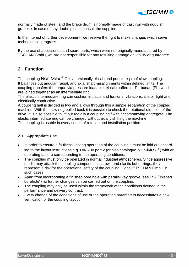
Assembly and operating instructions TSCHAN® Elastic coupling
Nor-Mex® G
bawn002-gbr-2 Nor-Mex G - 2 -
Content Chapter Page 1 Notes on safety ................................................................................................................ 2 2 Function ........................................................................................................................... 3
2.1 Appropriate Use ......................................................................................................... 3
3 Marking of the coupling .................................................................................................... 4 4 Storage............................................................................................................................. 4 5 Construction ..................................................................................................................... 5 6 Technical data .................................................................................................................. 6 7 Assembly .......................................................................................................................... 8
7.1 Pay attention before the assembly ............................................................................. 8
7.2 Finished borehole ....................................................................................................... 9 7.3 Installing coupling ..................................................................................................... 10
8 Adjusting coupling .......................................................................................................... 12
8.1 Angular misalignment Kw ....................................................................................... 13
8.2 Radial displacement Kr ........................................................................................... 13
8.3 Axial displacement ................................................................................................... 14 9 Operation ....................................................................................................................... 15
9.1 Sense of rotation test ............................................................................................... 18 10 Maintenance ................................................................................................................... 20
10.1 Wear Inspection on the Buffer Ring ......................................................................... 20 10.2 Wear limit of elastic buffers ...................................................................................... 21 10.3 Changing the elastic intermediate ring ..................................................................... 21
11 Waste Disposal .............................................................................................................. 23
1 Notes on safety The present assembly and operating instruction (AOI) constituents a part of the coupling supply. Always keep the AOI near the coupling well accessible. The German version of this manual is the predominant and binding version. Make sure that all persons charged with the assembly, operating, service, and maintenance have read and understood the AOI and follow all the points: - Avert hazards for body and live of the user and third parties. - Ensure the operating safety of the coupling. - Avoid the loss of use and environmental impairment through false handling. In the case of transport, mounting, dismounting and maintenance, attention is to be paid to the relevant regulations for industrial safety and for environmental care. The coupling may only be operated, mounted, serviced and maintained by authorised and trained personnel. The user must take into account that the bolting elements of coupling parts may be adversely affected by the heat produced by a brake disk/ brake drum due to the resultant friction. Make sure that the combination of the employed brake lining with the material of the brake disk/ brake drum does not lead to sparks or impermissible thermal growth. The brake disk is
bawn002-gbr-2 Nor-Mex G - 3 -
normally made of steel, and the brake drum is normally made of cast iron with nodular graphite. In case of any doubt, please consult the supplier! In the interest of further development, we reserve the right to make changes which serve technological progress. By the use of accessories and spare parts, which were not originally manufactured by TSCHAN GmbH, we are not responsible for any resulting damage or liability or guarantee.
2 Function
The coupling Nor-Mex ® G is a torsionally elastic and puncture-proof claw coupling.
It balances out angular, radial, and axial shaft misalignments within defined limits. The coupling transfers the torque via pressure loadable, elastic buffers or Perbunan (Pb) which are joined together as an intermediate ring. The elastic intermediate ring can cushion impacts and torsional vibrations; it is oil-tight and electrically conductive. A coupling half is divided in two and allows through this a simple separation of the coupled machine. With the claw ring pulled back it is possible to check the rotational direction of the drive. It is also possible to lift out radially a coupling half with accompanying aggregate. The elastic intermediate ring can be changed without axially shifting the machine. The coupling is usable in every sense of rotation and installation position. 2.1 Appropriate Use
In order to ensure a faultless, lasting operation of the coupling it must be laid out accord-
ing to the layout instructions e.g. DIN 730 part 2 (or also catalogue Nor-Mex ) with an
operating facture corresponding to the operating conditions.
The coupling must only be operated in normal industrial atmospheres. Since aggressive media may attack the coupling components, screws and elastic buffer rings, they represent a risk for the operational safety of the coupling. Consult TSCHAN GmbH in such cases.
Apart from incorporating a finished bore hole with parallel key groove (see “7.2 Finished borehole”) no further changes can be carried out on the coupling.
The coupling may only be used within the framework of the conditions defined in the performance and delivery contract.
Every change of the conditions of use or the operating parameters necessitates a new verification of the coupling layout.
bawn002-gbr-2 Nor-Mex G - 4 -
3 Marking of the coupling
The product line Nor-Mex ® has its hardness in Shore (A) indicated on the elastic interme-
diate ring.
4 Storage On receipt of the goods, the supply is to be checked immediately for completeness and correctness. Possible damages incurred during transit and / or missing parts are to be notified in writing. The coupling parts can be stored in their delivered standard-state for 6 months in a dry, roofed place at normal room temperature. For a longer storage duration a long-term preser-vation is necessary (consult TSCHAN GmbH). The elastic intermediate ring must not be subjected to ozone containing mediums, direct solar influence or strong light sources with ultraviolet-light. The relative humidity must not exceed 65%. In the case of proper storage the characteristics of the elastic intermediate ring remain unchanged for almost up to three years.
bawn002-gbr-2 Nor-Mex G - 5 -
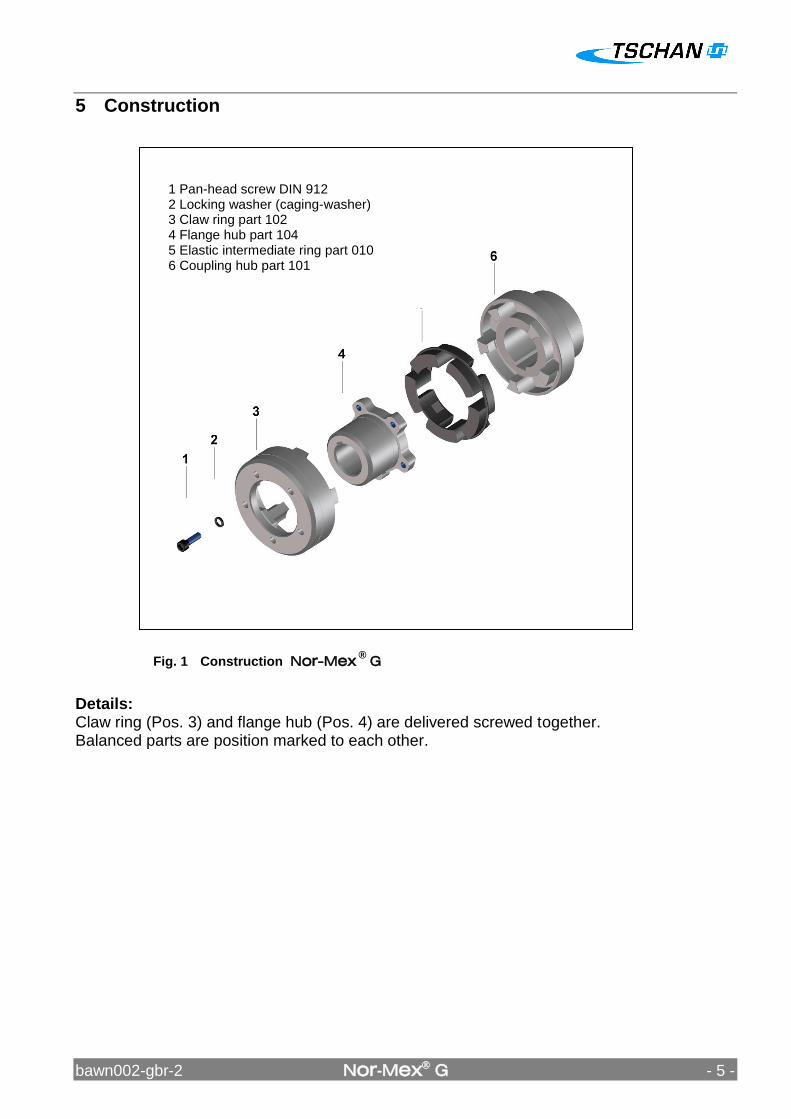
Fig. 1 Construction Nor-Mex ®
G
5 Construction
Details: Claw ring (Pos. 3) and flange hub (Pos. 4) are delivered screwed together. Balanced parts are position marked to each other.
1 Pan-head screw DIN 912 2 Locking washer (caging-washer) 3 Claw ring part 102 4 Flange hub part 104 5 Elastic intermediate ring part 010 6 Coupling hub part 101
bawn002-gbr-2 Nor-Mex G - 6 -
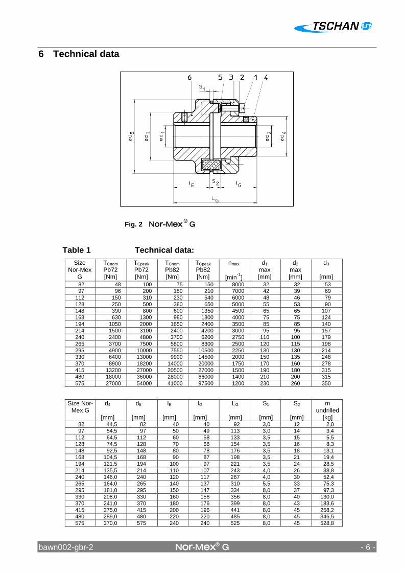
6 Technical data
Table 1 Technical data:
Size Nor-Mex
G
TCnom Pb72 [Nm]
TCpeak Pb72 [Nm]
TCnom Pb82 [Nm]
TCpeak Pb82 [Nm]
nmax
[min-1
]
d1 max [mm]
d2 max [mm]
d3
[mm]
82 48 100 75 150 8000 32 32 53
97 96 200 150 210 7000 42 39 69
112 150 310 230 540 6000 48 46 79
128 250 500 380 650 5000 55 53 90
148 390 800 600 1350 4500 65 65 107
168 630 1300 980 1800 4000 75 75 124
194 1050 2000 1650 2400 3500 85 85 140
214 1500 3100 2400 4200 3000 95 95 157
240 2400 4800 3700 6200 2750 110 100 179
265 3700 7500 5800 8300 2500 120 115 198
295 4900 10000 7550 10500 2250 130 130 214
330 6400 13000 9900 14500 2000 150 135 248
370 8900 18200 14000 20000 1750 170 160 278
415 13200 27000 20500 27000 1500 190 180 315
480 18000 36000 28000 66000 1400 210 200 315
575 27000 54000 41000 97500 1200 230 260 350
Size Nor-Mex G
d4
[mm]
d5
[mm]
lE
[mm]
lG
[mm]
LG
[mm]
S1
[mm]
S2
[mm]
m undrilled
[kg] 82 44,5 82 40 40 92 3,0 12 2,0
97 54,5 97 50 49 113 3,0 14 3,4
112 64,5 112 60 58 133 3,5 15 5,5
128 74,5 128 70 68 154 3,5 16 8,3
148 92,5 148 80 78 176 3,5 18 13,1
168 104,5 168 90 87 198 3,5 21 19,4
194 121,5 194 100 97 221 3,5 24 28,5
214 135,5 214 110 107 243 4,0 26 38,8
240 146,0 240 120 117 267 4,0 30 52,4
265 164,0 265 140 137 310 5,5 33 75,3
295 181,0 295 150 147 334 8,0 37 97,3
330 208,0 330 160 156 356 8,0 40 130,0
370 241,0 370 180 176 399 8,0 43 183,6
415 275,0 415 200 196 441 8,0 45 258,2
480 289,0 480 220 220 485 8,0 45 346,5
575 370,0 575 240 240 525 8,0 45 528,8
Fig. 2 Nor-Mex ®
G

bawn002-gbr-2 Nor-Mex G - 7 -
The torque TCnom and TCmax. is valid for: - Intermediate rings of Perbunan Pb72 and/or Pb82, - Ambient temperatures of -40 °C to +60 °C, - Operation within the stipulated alignment values.
During the layout of the coupling according to DIN 740 part 2 (or also catalogue Nor-Mex®)
different factors must be considered:
- with higher temperatures a corresponding temperature factor S - according to the starting frequency a starting factor Sz - in dependence of the operating conditions an impact factor, SA, SL With circumferential speeds of more than 22 m/s, we recommend to balance the coupling.
bawn002-gbr-2 Nor-Mex G - 8 -
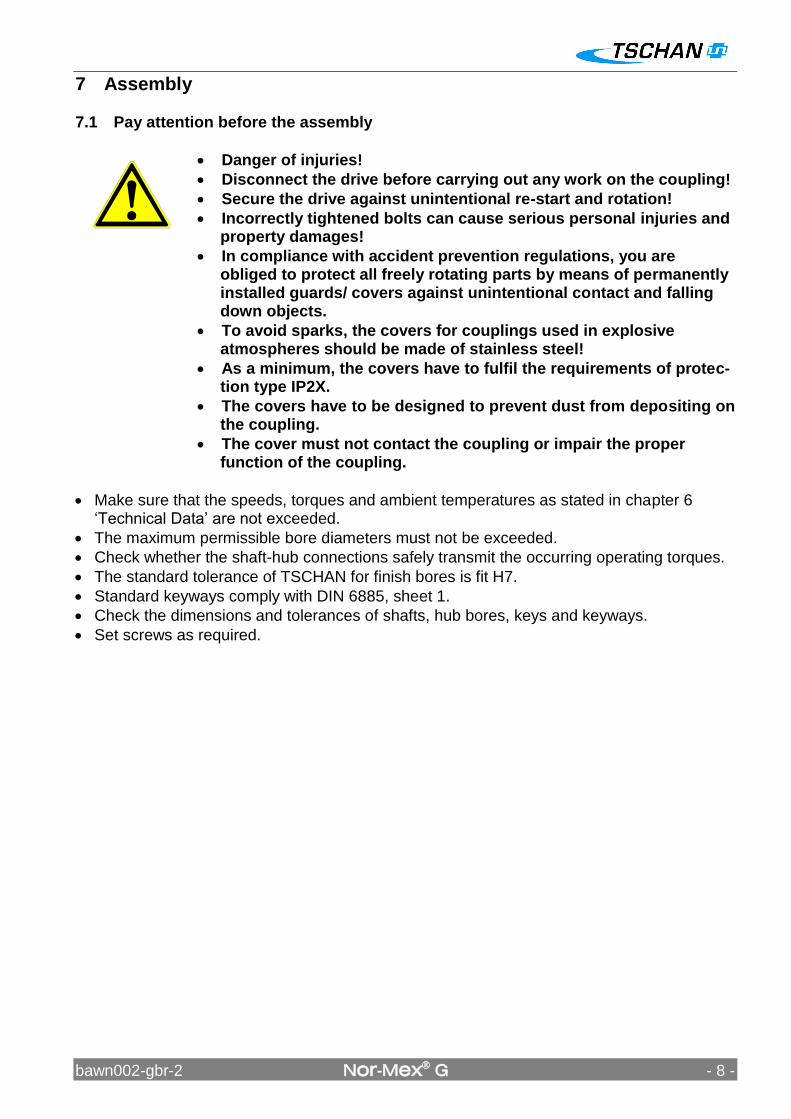
7 Assembly 7.1 Pay attention before the assembly Danger of injuries!
Disconnect the drive before carrying out any work on the coupling!
Secure the drive against unintentional re-start and rotation!
Incorrectly tightened bolts can cause serious personal injuries and property damages!
In compliance with accident prevention regulations, you are obliged to protect all freely rotating parts by means of permanently installed guards/ covers against unintentional contact and falling down objects.
To avoid sparks, the covers for couplings used in explosive atmospheres should be made of stainless steel!
As a minimum, the covers have to fulfil the requirements of protec-tion type IP2X.
The covers have to be designed to prevent dust from depositing on the coupling.
The cover must not contact the coupling or impair the proper function of the coupling.
Make sure that the speeds, torques and ambient temperatures as stated in chapter 6 „Technical Data‟ are not exceeded.
The maximum permissible bore diameters must not be exceeded.
Check whether the shaft-hub connections safely transmit the occurring operating torques.
The standard tolerance of TSCHAN for finish bores is fit H7.
Standard keyways comply with DIN 6885, sheet 1.
Check the dimensions and tolerances of shafts, hub bores, keys and keyways.
Set screws as required.
bawn002-gbr-2 Nor-Mex G - 9 -
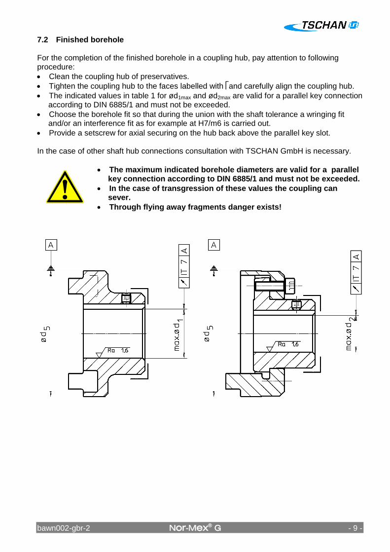
7.2 Finished borehole For the completion of the finished borehole in a coupling hub, pay attention to following procedure:
Clean the coupling hub of preservatives.
Tighten the coupling hub to the faces labelled with and carefully align the coupling hub.
The indicated values in table 1 for ød1max and ød2max are valid for a parallel key connection according to DIN 6885/1 and must not be exceeded.
Choose the borehole fit so that during the union with the shaft tolerance a wringing fit and/or an interference fit as for example at H7/m6 is carried out.
Provide a setscrew for axial securing on the hub back above the parallel key slot. In the case of other shaft hub connections consultation with TSCHAN GmbH is necessary. The maximum indicated borehole diameters are valid for a parallel
key connection according to DIN 6885/1 and must not be exceeded.
In the case of transgression of these values the coupling can sever.
Through flying away fragments danger exists!
bawn002-gbr-2 Nor-Mex G - 10 -
Fig. 4
Fig. 3
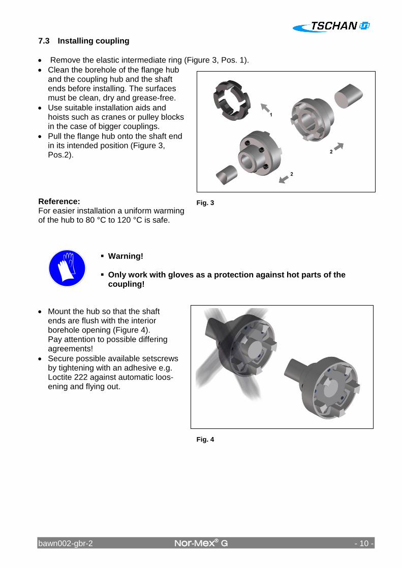
7.3 Installing coupling
Remove the elastic intermediate ring (Figure 3, Pos. 1).
Clean the borehole of the flange hub and the coupling hub and the shaft ends before installing. The surfaces must be clean, dry and grease-free.
Use suitable installation aids and hoists such as cranes or pulley blocks in the case of bigger couplings.
Pull the flange hub onto the shaft end in its intended position (Figure 3, Pos.2).
Reference: For easier installation a uniform warming of the hub to 80 °C to 120 °C is safe.
Warning! Only work with gloves as a protection against hot parts of the
coupling!
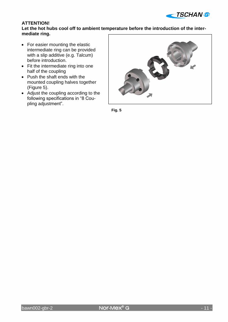
Mount the hub so that the shaft ends are flush with the interior borehole opening (Figure 4). Pay attention to possible differing agreements!
Secure possible available setscrews by tightening with an adhesive e.g. Loctite 222 against automatic loos-ening and flying out.
bawn002-gbr-2 Nor-Mex G - 11 -
Fig. 5
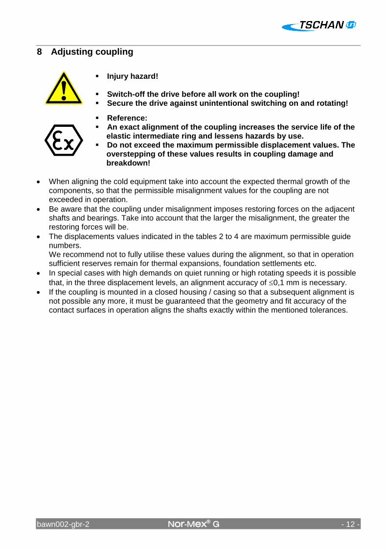
ATTENTION! Let the hot hubs cool off to ambient temperature before the introduction of the inter-mediate ring.
For easier mounting the elastic intermediate ring can be provided with a slip additive (e.g. Talcum) before introduction.
Fit the intermediate ring into one half of the coupling
Push the shaft ends with the mounted coupling halves together (Figure 5).
Adjust the coupling according to the following specifications in “8 Cou-pling adjustment”.
bawn002-gbr-2 Nor-Mex G - 12 -
8 Adjusting coupling
Injury hazard! Switch-off the drive before all work on the coupling! Secure the drive against unintentional switching on and rotating!
Reference: An exact alignment of the coupling increases the service life of the
elastic intermediate ring and lessens hazards by use. Do not exceed the maximum permissible displacement values. The
overstepping of these values results in coupling damage and breakdown!
When aligning the cold equipment take into account the expected thermal growth of the components, so that the permissible misalignment values for the coupling are not exceeded in operation.
Be aware that the coupling under misalignment imposes restoring forces on the adjacent shafts and bearings. Take into account that the larger the misalignment, the greater the restoring forces will be.
The displacements values indicated in the tables 2 to 4 are maximum permissible guide numbers. We recommend not to fully utilise these values during the alignment, so that in operation sufficient reserves remain for thermal expansions, foundation settlements etc.
In special cases with high demands on quiet running or high rotating speeds it is possible
that, in the three displacement levels, an alignment accuracy of 0,1 mm is necessary.
If the coupling is mounted in a closed housing / casing so that a subsequent alignment is not possible any more, it must be guaranteed that the geometry and fit accuracy of the contact surfaces in operation aligns the shafts exactly within the mentioned tolerances.
bawn002-gbr-2 Nor-Mex G - 13 -
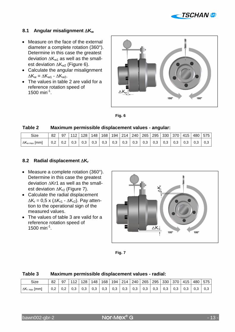
8.1 Angular misalignment Kw
Measure on the face of the external diameter a complete rotation (360°). Determine in this case the greatest
deviation Kw1 as well as the small-
est deviation Kw2 (Figure 6).
Calculate the angular misalignment
Kw = Kw1 - Kw2.
The values in table 2 are valid for a reference rotation speed of 1500 min-1.
Table 2 Maximum permissible displacement values - angular:
Size 82 97 112 128 148 168 194 214 240 265 295 330 370 415 480 575
Kw max [mm] 0,2 0,2 0,3 0,3 0,3 0,3 0,3 0,3 0,3 0,3 0,3 0,3 0,3 0,3 0,3 0,3
8.2 Radial displacement Kr
Measure a complete rotation (360°). Determine in this case the greatest
deviation Kr1 as well as the small-
est deviation Kr2 (Figure 7).
Calculate the radial displacement
Kr = 0,5 x (Kr1 - Kr2). Pay atten-tion to the operational sign of the measured values.
The values of table 3 are valid for a reference rotation speed of 1500 min-1.
Table 3 Maximum permissible displacement values - radial:
Size 82 97 112 128 148 168 194 214 240 265 295 330 370 415 480 575
Kr max [mm] 0,2 0,2 0,3 0,3 0,3 0,3 0,3 0,3 0,3 0,3 0,3 0,3 0,3 0,3 0,3 0,3
Fig. 6
Fig. 7
bawn002-gbr-2 Nor-Mex G - 14 -
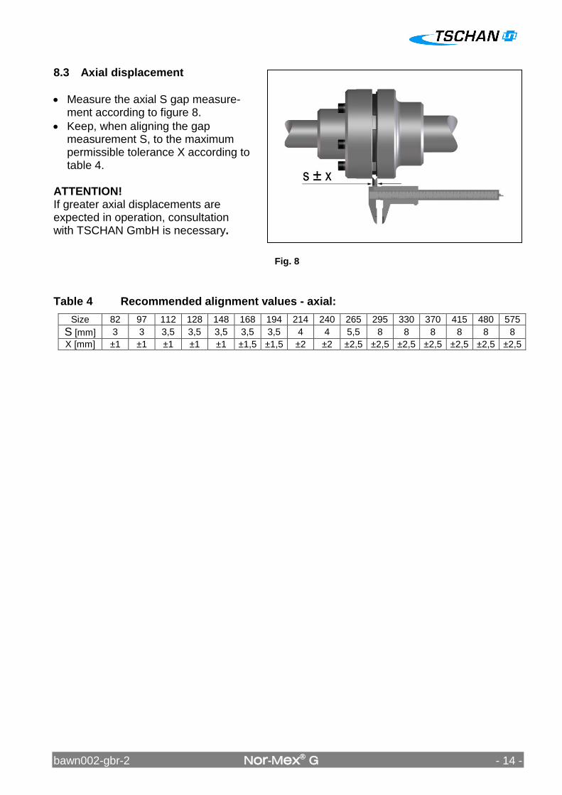
8.3 Axial displacement
Measure the axial S gap measure-ment according to figure 8.
Keep, when aligning the gap measurement S, to the maximum permissible tolerance X according to table 4.
ATTENTION! If greater axial displacements are expected in operation, consultation with TSCHAN GmbH is necessary.
Table 4 Recommended alignment values - axial:
Size 82 97 112 128 148 168 194 214 240 265 295 330 370 415 480 575
S [mm] 3 3 3,5 3,5 3,5 3,5 3,5 4 4 5,5 8 8 8 8 8 8
X [mm] ±1 ±1 ±1 ±1 ±1 ±1,5 ±1,5 ±2 ±2 ±2,5 ±2,5 ±2,5 ±2,5 ±2,5 ±2,5 ±2,5
Fig. 8
bawn002-gbr-2 Nor-Mex G - 15 -
9 Operation When using the coupling attention is to be paid to its characteristics (see „6 Technical data”). These can in no case be exceeded without having a written agreement from TSCHAN GmbH. In order to guarantee a faultless, lasting operation of the coupling, it must be laid out accord-
ing to the regulations e.g. DIN 740 part 2 (or according to catalogue Nor-Mex) with an
operating factor corresponding to its operating conditions. Every change of the conditions of use or the operating parameters makes an inspection of the coupling layout urgently necessary.
Injury danger! Switch-off the drive before all work on the coupling! Secure the drive against unintentional switch-on and rotating! Due to incorrectly tightened screws parts can fly away and cause
serious injuries to persons and damage to material! Check before commissioning the coupling the alignment and all
screw fastenings for their specified tightening torque and/or firm seating!
Before commissioning the plant install all protective devices against unintentional touching of free moving and/or rotating parts.
To avoid sparks coverings in stainless steel should be used! The coverings must fulfil at least the protection type IP2X. The covering is to be so designed that it does not deposit dust onto
the coupling parts. The covering must not touch the coupling or influence it in its
functioning. Pay attention during the operation of the coupling to: Changed running noises Occurring vibrations Attention!
If irregularities are found during operation of the coupling, the drive must be immediately switched off.
Detect according to the following table 5, “Operating faults and their possible causes” the faults and remove. The listed faults are some examples which are supposed to facilitate fault location.
For fault finding and elimination all machine components and operating states are to be considered!
bawn002-gbr-2 Nor-Mex G - 16 -
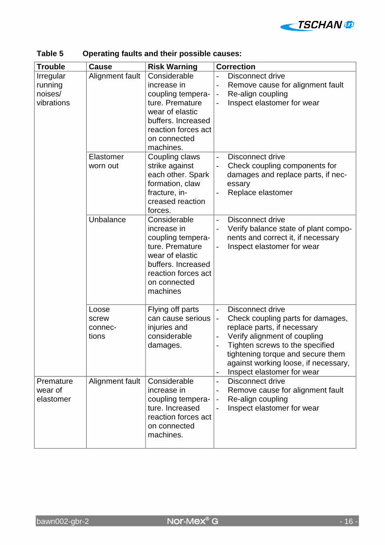
Table 5 Operating faults and their possible causes:
Trouble Cause Risk Warning Correction
Irregular running noises/ vibrations
Alignment fault Considerable increase in coupling tempera-ture. Premature wear of elastic buffers. Increased reaction forces act on connected machines.
- Disconnect drive - Remove cause for alignment fault - Re-align coupling - Inspect elastomer for wear
Elastomer worn out
Coupling claws strike against each other. Spark formation, claw fracture, in-creased reaction forces.
- Disconnect drive - Check coupling components for
damages and replace parts, if nec-essary
- Replace elastomer
Unbalance Considerable increase in coupling tempera-ture. Premature wear of elastic buffers. Increased reaction forces act on connected machines
- Disconnect drive - Verify balance state of plant compo-
nents and correct it, if necessary - Inspect elastomer for wear
Loose screw connec-tions
Flying off parts can cause serious injuries and considerable damages.
- Disconnect drive - Check coupling parts for damages,
replace parts, if necessary - Verify alignment of coupling - Tighten screws to the specified
tightening torque and secure them against working loose, if necessary,
- Inspect elastomer for wear
Premature wear of elastomer
Alignment fault Considerable increase in coupling tempera-ture. Increased reaction forces act on connected machines.
- Disconnect drive - Remove cause for alignment fault - Re-align coupling - Inspect elastomer for wear
bawn002-gbr-2 Nor-Mex G - 17 -
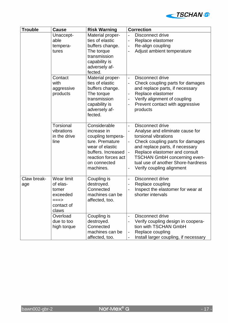
Trouble Cause Risk Warning Correction
Unaccept-able tempera-tures
Material proper-ties of elastic buffers change. The torque transmission capability is adversely af-fected.
- Disconnect drive - Replace elastomer - Re-align coupling - Adjust ambient temperature
Contact with aggressive products
Material proper-ties of elastic buffers change. The torque transmission capability is adversely af-fected.
- Disconnect drive - Check coupling parts for damages
and replace parts, if necessary - Replace elastomer - Verify alignment of coupling - Prevent contact with aggressive
products
Torsional vibrations in the drive line
Considerable increase in coupling tempera-ture. Premature wear of elastic buffers. Increased reaction forces act on connected machines.
- Disconnect drive - Analyse and eliminate cause for
torsional vibrations - Check coupling parts for damages
and replace parts, if necessary - Replace elastomer and consult
TSCHAN GmbH concerning even-tual use of another Shore-hardness
- Verify coupling alignment
Claw break-age
Wear limit of elas-tomer exceeded ===> contact of claws
Coupling is destroyed. Connected machines can be affected, too.
- Disconnect drive - Replace coupling - Inspect the elastomer for wear at
shorter intervals
Overload due to too high torque
Coupling is destroyed. Connected machines can be affected, too.
- Disconnect drive - Verify coupling design in coopera-
tion with TSCHAN GmbH - Replace coupling - Install larger coupling, if necessary
bawn002-gbr-2 Nor-Mex G - 18 -
9.1 Sense of rotation test
Injury danger! Switch-off the drive before all work on the coupling! Secure the drive against unintentional switching on and rotating! Due to incorrectly screwed on screws, parts can fly away and
cause person and material damage! Check before commissioning the coupling the alignment and all
screw fixings for their specified tightening torque and/or firm seat-ing!
Before commissioning the plant all protective devices against unintentional touching of free moving and/or rotating parts must be installed.
To avoid sparks coverings should be made of stainless steel! The coverings must fulfil at least the protection type IP2X. The covering is to be designed in such a way that it does not
deposit dust onto the coupling parts. The covering must not touch the coupling and/or influence it in its
function. Attention!
A sense of rotation test can only be carried out if the coupling flange is mounted onto the aggregate drive-side! Otherwise spark-ing hazards exist through the pushed back claw ring!
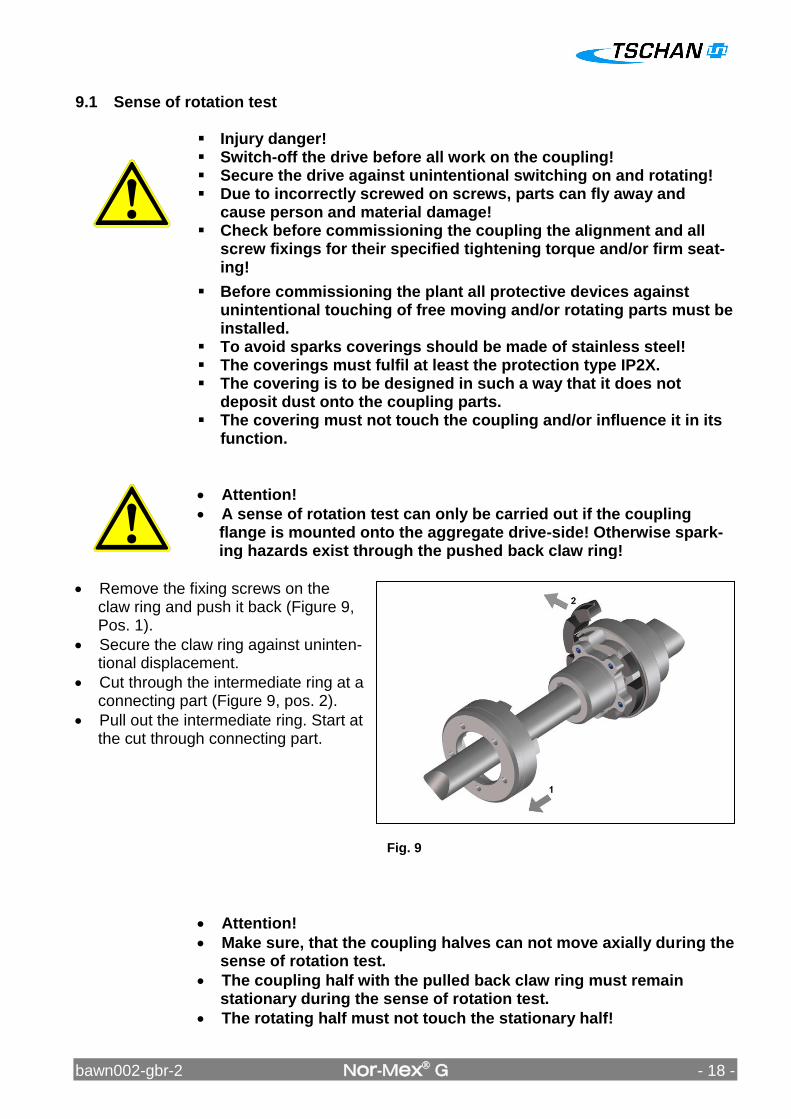
Remove the fixing screws on the claw ring and push it back (Figure 9, Pos. 1).
Secure the claw ring against uninten-tional displacement.
Cut through the intermediate ring at a connecting part (Figure 9, pos. 2).
Pull out the intermediate ring. Start at the cut through connecting part.
Attention!
Make sure, that the coupling halves can not move axially during the sense of rotation test.
The coupling half with the pulled back claw ring must remain stationary during the sense of rotation test.
The rotating half must not touch the stationary half!
Fig. 9
bawn002-gbr-2 Nor-Mex G - 19 -
After the sense of rotation test, cut through a new intermediate ring at a connecting part and fit it between coupling hub and flange.
To obtain an easier mounting one can provide the new elastic intermediate ring with a slip additive before its introduction (e.g. talcum powder).
Attention! The bearing surface of the claw ring and flange hub must be clean, dry and grease-free. Balanced parts are position marked to each other.
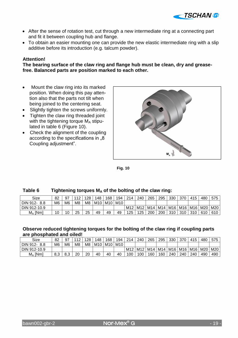
Mount the claw ring into its marked position. When doing this pay atten-tion also that the parts not tilt when being joined to the centering seat.
Slightly tighten the screws uniformly.
Tighten the claw ring threaded joint with the tightening torque MA stipu-lated in table 6 (Figure 10).
Check the alignment of the coupling according to the specifications in „8 Coupling adjustment”.
Table 6 Tightening torques MA of the bolting of the claw ring:
Size 82 97 112 128 148 168 194 214 240 265 295 330 370 415 480 575
DIN 912- 8.8 M6 M6 M8 M8 M10 M10 M10
DIN 912-10.9 M12 M12 M14 M14 M16 M16 M16 M20 M20
MA [Nm] 10 10 25 25 49 49 49 125 125 200 200 310 310 310 610 610
Observe reduced tightening torques for the bolting of the claw ring if coupling parts are phosphated and oiled!
Size 82 97 112 128 148 168 194 214 240 265 295 330 370 415 480 575
DIN 912- 8.8 M6 M6 M8 M8 M10 M10 M10
DIN 912-10.9 M12 M12 M14 M14 M16 M16 M16 M20 M20
MA [Nm] 8,3 8,3 20 20 40 40 40 100 100 160 160 240 240 240 490 490
Fig. 10
bawn002-gbr-2 Nor-Mex G - 20 -
10 Maintenance
The elastic coupling Nor-Mex ®-G has in operation a low-maintenance.
Reaching the wear limit of the elastic intermediate ring depends on the operating parameters and the conditions of use. In the case of routine monitoring work on the plant check:
Alignment of the coupling
Elastomer state
Remove dust deposits from the coupling parts and the intermediate ring 10.1 Wear Inspection on the Buffer Ring
Danger of injuries! Disconnect the drive before carrying out any work on the
coupling! Secure the drive against unintentional switching on and rotating!
Perform a visual inspection and a wear inspection of the buffer ring after 2000 hours, or after 3 months at latest, after the first start-up of the equip-ment. If only minor wear or no wear is observed, further inspections of the plant can be carried out at regular intervals of 4000 hours, however, at least once a year, if the operating modes and conditions of the plant remain unchanged. However, should you observe excessive wear on the occasion of this first inspection already, check whether the cause for the problem is listed in table 5 “Operation faults and possible causes”. In such a case, the inspection intervals must be adapted to the prevailing service conditions.
On the occasion of routine inspections or maintenance work on the drive equipment, or after 3 years at latest:
Replace the elastic buffer ring.
If the wear limit has been reached or exceeded, replace the buffer ring immediately, irrespective of the inspection intervals of the equipment.
Check the alignment of the coupling.
Remove dust deposits from the coupling components and buffer ring.
bawn002-gbr-2 Nor-Mex G - 21 -
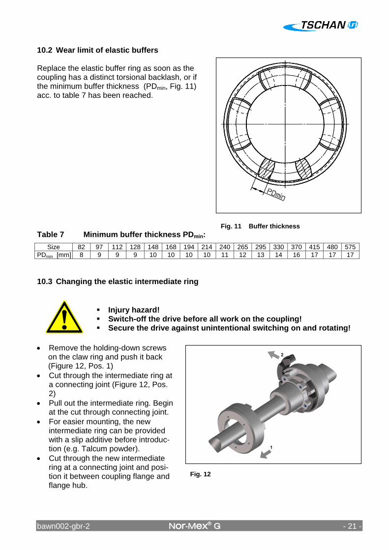
Fig. 12
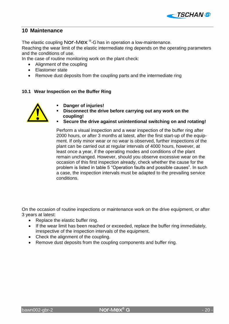
Fig. 11 Buffer thickness
10.2 Wear limit of elastic buffers Replace the elastic buffer ring as soon as the coupling has a distinct torsional backlash, or if the minimum buffer thickness (PDmin, Fig. 11) acc. to table 7 has been reached.
Table 7 Minimum buffer thickness PDmin:
Size 82 97 112 128 148 168 194 214 240 265 295 330 370 415 480 575
PDmin [mm] 8 9 9 9 10 10 10 10 11 12 13 14 16 17 17 17
10.3 Changing the elastic intermediate ring
Injury hazard! Switch-off the drive before all work on the coupling! Secure the drive against unintentional switching on and rotating!
Remove the holding-down screws on the claw ring and push it back (Figure 12, Pos. 1)
Cut through the intermediate ring at a connecting joint (Figure 12, Pos. 2)
Pull out the intermediate ring. Begin at the cut through connecting joint.
For easier mounting, the new intermediate ring can be provided with a slip additive before introduc-tion (e.g. Talcum powder).
Cut through the new intermediate ring at a connecting joint and posi-tion it between coupling flange and flange hub.
bawn002-gbr-2 Nor-Mex G - 22 -
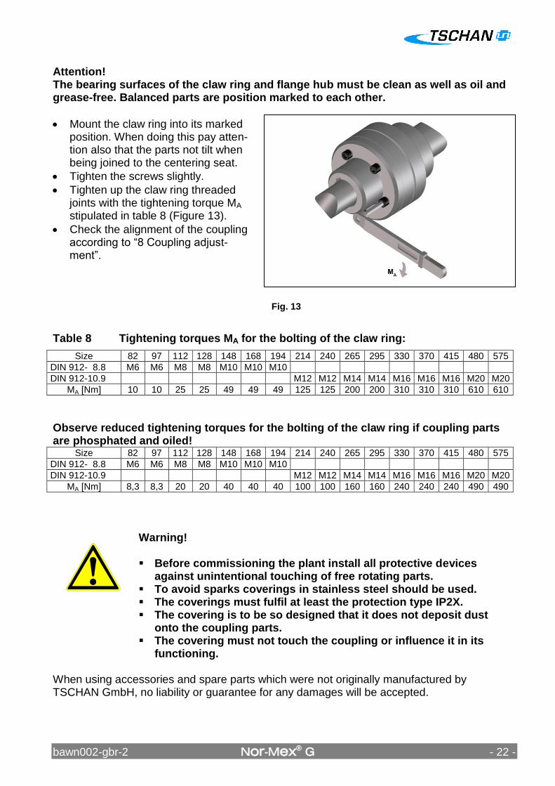
Attention! The bearing surfaces of the claw ring and flange hub must be clean as well as oil and grease-free. Balanced parts are position marked to each other.
Mount the claw ring into its marked position. When doing this pay atten-tion also that the parts not tilt when being joined to the centering seat.
Tighten the screws slightly.
Tighten up the claw ring threaded joints with the tightening torque MA stipulated in table 8 (Figure 13).
Check the alignment of the coupling according to “8 Coupling adjust-ment”.
Table 8 Tightening torques MA for the bolting of the claw ring:
Size 82 97 112 128 148 168 194 214 240 265 295 330 370 415 480 575
DIN 912- 8.8 M6 M6 M8 M8 M10 M10 M10
DIN 912-10.9 M12 M12 M14 M14 M16 M16 M16 M20 M20
MA [Nm] 10 10 25 25 49 49 49 125 125 200 200 310 310 310 610 610
Observe reduced tightening torques for the bolting of the claw ring if coupling parts are phosphated and oiled!
Size 82 97 112 128 148 168 194 214 240 265 295 330 370 415 480 575
DIN 912- 8.8 M6 M6 M8 M8 M10 M10 M10
DIN 912-10.9 M12 M12 M14 M14 M16 M16 M16 M20 M20
MA [Nm] 8,3 8,3 20 20 40 40 40 100 100 160 160 240 240 240 490 490
Warning! Before commissioning the plant install all protective devices
against unintentional touching of free rotating parts. To avoid sparks coverings in stainless steel should be used. The coverings must fulfil at least the protection type IP2X. The covering is to be so designed that it does not deposit dust
onto the coupling parts. The covering must not touch the coupling or influence it in its
functioning. When using accessories and spare parts which were not originally manufactured by TSCHAN GmbH, no liability or guarantee for any damages will be accepted.
Fig. 13
bawn002-gbr-2 Nor-Mex G - 23 -
11 Waste Disposal The waste disposal has to occur according to the specific regulations of the respective user country.