assembly instructions for - · pdf fileassembly instructions for ... appendix d part of...
TRANSCRIPT

Assembly Instructions for
RA553455S1..Gearbox AssemblyMRA-200..Gearbox internal parts kit.
(SK-1698.....Fork setting fixture)
Conversion for Lancer Evolution

Table of Contents
Section Description Page
1. Preparation 1
2. Layshaft Assembly 2
3. Mainshaft Assembly 3
4. Fork Setting 6
5. Final Assembly 9
Appendix A Parts List 11
Appendix B Assembly Drawing 12
Appendix C Gearbox Parts as Packed 13
Appendix D Part of Ralliart Manual 15
Appendix E Spacer List for Adjustment 16

Deconstruct the existing gearbox and set aside the following items forfuture use:
1. All casings and external mechanisms.2. 1st/2nd selector head including roll pin.3. 5th/reverse selector head including roll pin.4. 16 x Maincase bolts.
(M10x40 - MF140266)5. 4 x Gear shift shaft bolts and washers.
(M8X25 - MF140227)6. 2 x Selector shaft bolts and washers.
(M8X22- MF241254)7. 6 x Sump tray bolts.
(M6X10 - MD0970128. Reverse idler retaining bolts and wash’r.
(M10X46 - MD749978)9. 3 x Detents
(MD7499435 - or option - see appendix A)10. Reverse switch (MD730979)11. Drain plug (MD701850)12. Final drive wheel retaing bolt13. Reverse idler post14. Differential (complete)
Page 1
1. Preparation
1
32
87654
1110
9
1413
12

Press off bearings from the original layshaft using Raliart tool #MD998801, as shown in fig 2-1 and fig2-2 and remove seals from the maincase bearing.
Build the layshaft assembly engaging MRA-235-17/25 Hub Gear (#28a), MRA-235-18/20 (#8a) andMRA-235-28/24 (#12a) gears onto the splined shaft MRA-234 (#10a). Secure the assembly by fittingcirclip CIR-076 (#25).
Press the bearings retained from the original shaft onto the assembly and fit circlipFT-219-1A (#13).
Page 2
Fig 2-3. Layshaft Assembly
Existing Bearings
10a
8a12a
25
28a
13
2. Layshaft Assembly
fig 2-1 fig 2-2

Use the fork setting fixture (SK-1698) to assist in assembling the mainshaft.
Place the mainshaft (MRA-221 - #9a) into the fork setting fixture (fig 3-1).
Slide mainshaft spacer MRA-221-1 (#16) onto the mainshaft (fig 3-2).
Place MRA-233-13/26 pinion gear (#10c) and bearingBEA-029 (#14) onto the smooth bore, splined, end ofhub MRA-226 (#20) (fig 3-3a). Fit clutch ring DGB-232-S (#24) onto the hub external spline, completingthe sub assembly by fitting MRA-233-12/36 piniongear (#10b), and bearing BEA-029 (#14).
Engage the sub assembly onto the mainshaft splines, smooth bore side first (fig 3-3), followed bymainshaft hub spacer MRA-221-2 (#15) (fig 3-4).
Page 3
3. Mainshaft Assembly
fig 3-1. fig 3-2.
fig 3-3a
Hub - MRA-226
Splinedend
non-Splinedend
Fork settingfixture -SK-1698
9a
16
fig 3-3. fig 3-4.
2010c
24
14
10b
15

Follow the same procedure for the sub assembly of MRA-233-17/25 pinion gear (#28b) and bearing BEA-029 (#14) onto the endof 3rd/4th hub ST-228 (#21).
Engage clutch ring DGB-232-S (#24) onto the hub external spline,completing the sub assembly by fittingMRA-233-18/20 pinion gear(#8b) and 3rd/4th hub ST-228 (#21).
Engage the sub assembly onto the mainshaft splines, MRA-233-17/25 pinion gear (#28b) towards the final drive. Fit the second mainshaft hub spacer.MRA-221-2(#15).
The same procedure is followed for the sub assembly ofMRA-233-28/24 pinion gear (#12b) and bearing BEA-029 (#14) onto the end of hub MRA-228 (#22).
Engage clutch ring DGB-232-S (#24) onto the hub exter-nal spline, completing the sub assembly by fittingreverse pinion gear MRA-231 (#26), making sure the 5thgear is placed on the stepped end of 5th/REV hub MRA-228 (#22) (fig 3-7a).
Page 4
fig 3-5a
Hub - ST-228Splinedbothends
fig 3-5.
218b
24
1428b
fig 3-6.
15
221412b
Stepped endfig 3-7a.

Engage the third hub onto the mainshaft with MRA-233-28:24 pinion gear (#12b) towards the finaldrive (fig 3-7).
Fit mainshaft spacer MRA-221-3 (#23)with its larger face towards the reversegear (fig 3-8 and 3-8a).
Press the inner race of bearing BEA-148 (#17) up to the spacer and secure with circlipFT-219-1A (#13). Insert the oil seal (#19) in the mainshaft (fig 3-9).
Page 5
fig 3-7.
24
262214
12b
fig 3-8.
fig 3-8a.
23 - Ensurestepped face isaway from gear
fig 3-9.
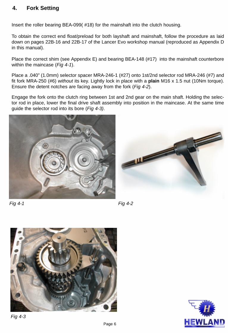
Insert the roller bearing BEA-099( #18) for the mainshaft into the clutch housing.
To obtain the correct end float/preload for both layshaft and mainshaft, follow the procedure as laiddown on pages 22B-16 and 22B-17 of the Lancer Evo workshop manual (reproduced as Appendix Din this manual).
Place the correct shim (see Appendix E) and bearing BEA-148 (#17) into the mainshaft counterborewithin the maincase (Fig 4-1).
Place a .040” (1.0mm) selector spacer MRA-246-1 (#27) onto 1st/2nd selector rod MRA-246 (#7) andfit fork MRA-250 (#6) without its key. Lightly lock in place with a plain M16 x 1.5 nut (10Nm torque).Ensure the detent notches are facing away from the fork (Fig 4-2).
Engage the fork onto the clutch ring between 1st and 2nd gear on the main shaft. Holding the selec-tor rod in place, lower the final drive shaft assembly into position in the maincase. At the same timeguide the selector rod into its bore (Fig 4-3).
Fig 4-1 Fig 4-2
Fig 4-3
4. Fork Setting
Page 6

Fit the fork setting fixture over the final drive spigoton the mainshaft and selector rod. Using four (4)maincase bolts lightly secure the fixture (10Nmtorque) (Fig 4-4).
Set the selector rod to the neutral position (centrenotch) by looking through the detent hole and fit oneof the original detents (Fig 4-5).
Using a mirror inspect the fork setting (Fig 4-6). Thedogs on the clutch ring must be mid way betweenthe dogs on the 1st and 2nd pinion gears. Shouldminor adjustments be necessary, the spacer MRA-246-1 (#27) can either be ground to size, orreplaced with a thicker spacer suitably ground to
size.
Having obtained the correct fork setting, remove the mainshaft and set aside the selector rod and fork.
Follow the same procedure as above, using another .040”(1.0mm) spacer MRA-246-1 (#27) to assem-ble the 3rd/4th rod MRA-247-A (#4) and fork MRA-251(#5) (without its key). Having fitted the mainshaft,selector rod assembly and detent in place with the fixing jig.
As a guide, a .046”(1.15mm) spacer MRA-246-1 (#27)is required to fit the 5th/REV selector rod MRA-248 (#2)and fork MRA-252 (#3) . Build in the same way as theother rods (without its key) and fit the assembly, againwith the aid of the fixing jig. Fork setting inspection canbe made through the “sump plate” aperture adjacent tothe reverse idler gear. Again, any adjustments must bemade by grinding the spacer to the required size.
Remove the mainshaft and 5th/REV rod. Fit the appro-priate keys (DG-256-6 (#29) and MRA-248 (#30))toeach fork, and, using Fig 4-7 as a guide, lock each forkto its rod with NUT020 (#1) asillustrated.
Fig 4-5
Fig 4-6
Fig 4-7
Fig 4-4
Page 7
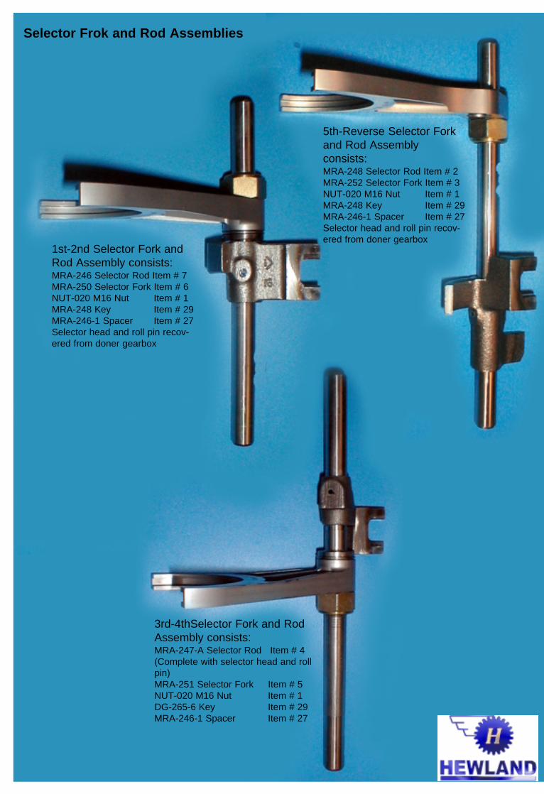
5th-Reverse Selector Forkand Rod Assembly consists:MRA-248 Selector Rod Item # 2MRA-252 Selector Fork Item # 3NUT-020 M16 Nut Item # 1MRA-248 Key Item # 29MRA-246-1 Spacer Item # 27Selector head and roll pin recov-ered from doner gearbox
1st-2nd Selector Fork andRod Assembly consists:MRA-246 Selector Rod Item # 7MRA-250 Selector Fork Item # 6NUT-020 M16 Nut Item # 1MRA-248 Key Item # 29MRA-246-1 Spacer Item # 27Selector head and roll pin recov-ered from doner gearbox
Selector Frok and Rod Assemblies
3rd-4thSelector Fork and RodAssembly consists:MRA-247-A Selector Rod Item # 4(Complete with selector head and rollpin)MRA-251 Selector Fork Item # 5NUT-020 M16 Nut Item # 1DG-265-6 Key Item # 29MRA-246-1 Spacer Item # 27

Fit the final drive wheel to the existing differential using the original bolts tightened to 132Nm withLoctite 648
Fit the outer bearing, BEA-099 (#18) into the appropriate counterbore in the clutch housing. Place thedifferential assembly into the clutch housing.
Fit the fork assembly onto the three clutch rings (Fig 5-1) and, while held in place, mesh the layshaftand its gears into engagement with drive gears on the mainshaft(Fig 5-2). Holding both shafts and theselector rods locked together (Fig 5-3), lower the complete assembly into the clutch housing (Fig 5-4). The layshaft should be guided through the oil seal allowing its bearing to locate in the bellhousing.The mainshaft will engage in the final drive wheel and its bearing into the outer race. At the sametime the three selector rods will align with their respective location bores.
Page 9
Fig 5-1.
Fig 5-4.
Fig 5-2.
Fig 5-3.
5. Final Assembly

Place bearing BEA-148 (#17) onto it’s inner race on the mainshaft.
Using heavy grease, hold the layshaft and mainshaft shims into their counterbores in the maincase.Using Hylamar to seal the faces, lower the maincase onto the gear assembly. Check that theselector rods are free by sliding them through their travel before finally bolting up the cases(44Nm).Fit the detents to the selector rods in the neutral position. Replace the selector mechanism and itslocking pin.
Exchange the reverse idler gear MRA-237 (#11) using the original spacers and circlip. Remount in itscradle inside the sump aperture and fit the plate using sealant.
Page 10

Page 11
Appendix A Parts ListComponent Part Number Description Qty. Per
RA553455S1 GEARBOX ASSEMBLY 1
MRA-200 GEARBOX INTERNALPARTS KIT 1
1 NUT-020 M16 NUT 32 MRA-248 SELECTOR ROD - 5TH/REV 13 MRA-252 SELECTOR FORK - 5TH/REV 14 MRA-247-A SELECTOR ROD 3rd/4th- ASSY 15 MRA-251 SELECTOR FORK - 3RD/4TH 16 MRA-250 SELECTOR FORK - 1ST/2ND 17 MRA-246 SELECTOR ROD 18 MRA-4TH-SET 4TH GEAR SET - CONSISTS OF: 1
8a MRA-233-18/20 INPUT GEAR 18b MRA-235-18/20 PINION GEAR 1
9 MRA-221-SET MAINSHAFT AND FINAL DRIVE 110 MRA-234-SET LAYSHAFT SET - CONSISTS OF: 1
10a MRA-234 LAYSHAFT 110b MRA-233-12/36 PINION GEAR 110c MRA-233-13/26 PINION GEAR 111 MRA-237 REVERSE IDLER GEAR 112 MRA-5TH-SET 5TH GEAR SET - CONSISTS OF: 1
12a MRA-233-28/24 INPUT GEAR 112b MRA-235-28/24 PINION GEAR 113 FT-219-1A CIRCLIP 214 BEA-029 BEARING 615 MRA-221-2 MAINSHAFT SPACER - HUB 216 MRA-221-1 MAINSHAFT SPACER 117 BEA-148 BEARING (NJ207EC) 118 BEA-099 BEARING (NJ2207EC) 119 LIP-041 OIL SEAL 120 MRA-226 1ST/2ND HUB 121 ST-228 3RD/4TH HUB 122 MRA-228 5TH/REVERSE HUB 123 MRA-221-3 MAINSHAFT SPACER 124 DGB-232-S CLUTCH RING 325 CIR-076 CIRCLIP 126 MRA-231 REVERSE PINION GEAR 127 MRA-246-1 SELECTOR SPACER (3-OFF EACH) 128 MRA-3RD-SET 3RD GEAR SET - CONSISTS OF: 1
28a MRA-233-17/25 INPUT GEAR 128b MRA-235-17/25 PINION GEAR 129 DG-265-6 KEY 130 MRA-248-1 KEY 2
SK-1698 FORK SETTING FIXTURE 1
OPTION PARTS
For strong neutral shift return1 MD771659 SPRING, NEUTRAL RETURN 12 MD771658 SPRING, NEUTRAL RETURN 13 MD747930 DETENT 3
Evolution 7 conversion parts.1 MD771828 BRACKET ASSEMBLY, SHIFT CABLE 12 MD756706 SLEVE, SPEED METER DRIVEN GEAR 13 MD747055 GEAR SPEED SENSOR 14 MR581401 M/T CASE BRACKET 15 MF241250 BOLT, WASHER ASSEMBLY (M8X14) 1

Page 12
Appendix B Assembly Drawing
Page 13
9a
28a
9b10a
20
21
22
7
24
2
4
1
14
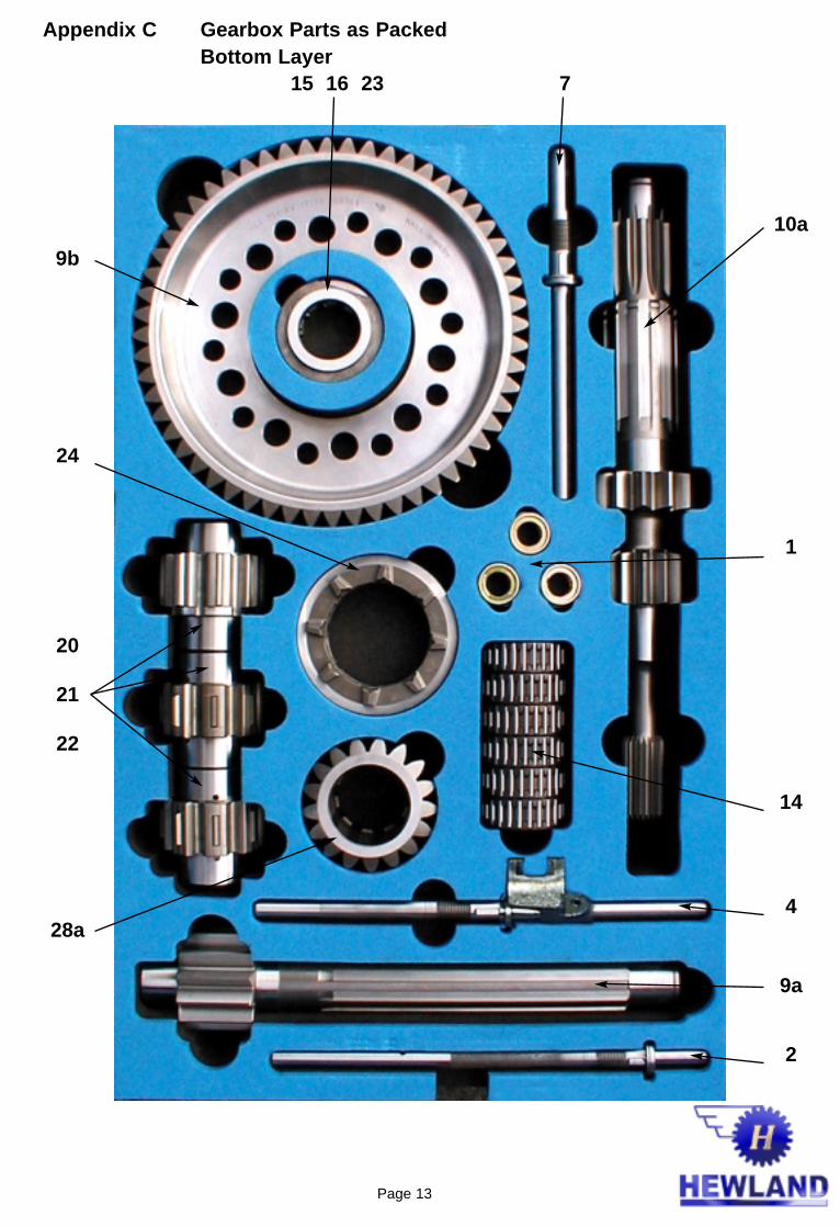
Appendix C Gearbox Parts as Packed
15 16 23 Bottom Layer

Page 14
6 35
26
12b
10b
11
28b
12a)
8a
10c
8b
17
18
Appendix C (cont’d) Gearbox Parts as Packed Top Layer

Page 15
REPRODUCED FROM LANCER EVOLUTION WORKSHOP MANUAL
ADJUSTMENT BEFORE ASSEMBLYSPACER SELECTION FOR ADJUSTING INPUTSHAFT END PLAY / OUTPUT SHAFT PRELOAD /DIFFERENTIAL PRELOAD(1) Install the input shaft, output shaft and centre differential
as a set to the clutch housing.
(2) Place two pieces of solder (1.6 mm in diameter and approx 10mm in length) on the input shaft rear bearing at the positions shown in the illustration.
(3) Place two pieces of solder (1.6 mm in diameter and approx 10mm in length) on the transmission case at the positions shown in the illustration.
(4) Install the bearing outer race.(5) Install the transmission case and tighten the bolts to the
specified torque.
(6) Remove the transmission case. If the solder is not crushed, repeat the steps (2) through (5) using solder with larger diameter.
Appendix D
(7) Measure the thickness of the crushed solder with a micrometer and select spacers that will provide the standard end play/proload value.Standard Value:Input shaft end play..............0 - 0.17 mmOutput shaft end play...........0.13 - 0.18 mmCentre differential preload...0.05 - 0.11 mm

Page 16
PART# THICKNESSMD723600 1.34MD723603 1.43MD723606 1.52MD723609 1.61MD756760 1.70MD756763 1.79
PART# THICKNESSMD720938 0.86MD720939 0.89MD720940 0.92MD720941 0.95MD720942 0.98MD720943 1.01MD720944 1.04MD720945 1.07MD710454 1.10MD700270 1.13MD710455 1.16MD710456 1.19MD700271 1.22MD710457 1.25MD710458 1.28MD706574 1.31MD710459 1.34MD710460 1.37MD710461 1.40MD710462 1.43
PART# THICKNESSMD727660 0.74MD754476 0.77MD727661 0.80MD720937 0.83MD720938 0.86MD720939 0.89MD720940 0.92MD720941 0.95MD720942 0.98MD720943 1.01MD720944 1.04MD720945 1.07MD710454 1.10MD700270 1.13MD710455 1.16MD710456 1.19MD700271 1.22MD710457 1.25MD710458 1.28MD706574 1.31
Appendix E Spacer List for Adjustment
Spacer M/T Input Shaft
Spacer M/T Differential
Spacer M/T Output Shaft