atin pae 'ainpg no alp-m 234 38tfhg'ie - dtic
TRANSCRIPT

'AINPG for~m Approvied- ATIN PAE [ MB No 0704-0188
co Ihour pe' fespor~e including the time to, ie..enwflg nhtrIn.CI ns searhin g iiniin sl-j data so.'(cfALP-M 234 38tfhg'ie c (Iecuon of' normnation wind (orme 6 1% reo;,nq this~ bu.rdie ' etinmte of any othier aspett Of this~en t") Washinngton mftif~aterS Se,or.C, Ore(l0 ale ior y,aton Ope 'a t 0 oand Okeport III$ jettersoie of Managemnent and Bu~dlet, Pa.perwork FRedu.ryof P,.""~ (0 704 -0 16). Wat'.ngton. DC 2050 3
1. AGENCY USE ONLY (Leavre bM7k 1. REPORT DATE 3. REPORT TYPE AND DATES COVERED
October 1990 memo4. TITLE AND SUBTITLE 5. FUNDING NUMBERS
Contact Sensing from Force Measurements 100014-86-K-0685NAG-9-319
6. AUTHOR(S)Antonio BicchiJ. Kenneth SalisburyDavid L. Brock_____________
7. PERFORMING ORGANIZATION NAME(S) AND ADDRESS(ES) 8. PERFORMING ORGANIZATION
Artificial Intelligence LaboratoryREOTNMR
545 Technology Square AIM 1262
Cambridge, Massachusetts 02139
9. SPONSORING/MO4NITORING AGENCY NAME(S) AND 1DRSR)0. SPONSORING I MONITORING
Office of Naval Research ADESS)AGENCY REPORT NUMBER
Information SystemsArlington, Virginia 22217 ~L C E
ADR 26 139t11. SUPPLEMENTARY NOTES
None5
12a. DISTRIBUTION! AVAILABILITY STATEMENT i2b. DISTRIBUTION CODE
Distribution of this document is unlimited
13. ABSTRACT (Ma ximum 200 wordi)
This paper addresses contact sensing, i.e. the problem of resolving thelocation of a contact, the force at the interface and the moment aboutthe contact normals. Called "intrinsic" contact sensing for the use of in-ternal force and torque measurements, this method allows for practicaldevices which provide simple, relevant contact information in practicalrobotic applications. Such sensors have been used in conjunction withrobot hands to identify objects, determine surface friction, detect slip,augment grasp stability, measure object mass, probe surfaces, controlcollision and a variety of other useful tasks. This paper describes thetheoretical basis for their operation and prr .,ides a framework for futuredevice design.
* 14. SUBJECT TERMS (key words) 1.NUMBER OF PAGES
Contact Sensing Dextrous Manipulation 1IECD
Contact Mechanics $46.00ICCD
17. SECURITY CLASSIFICATION 18. SECURITY CLASSIFICATI')N 19. SECURITY CLASSIFICATION 20. LIMITATION OF ABSTRACT
UNCLASSIFIED UNCLASSIFIED UNCLASSIFIED UJNCLASSIFIED
NSN 7540 01-280-5500 Standard Form 298 (Rev 2-89)P"res(rined by ANSI i ,d M3918298 102

MASSACHUSETTS INSTITUTE OF TECHNOLOGYARTIFICIAL INTELLIGENCE LABORATORY
A.I. Memo No. 1262 October 1990
Contact Sensing from Force Measurements
Antonio BicchiJ. Kenneth Salisbury
David L. Brock
Abstract
This paper addresses contact sensing, i.e. the problem of resolving thelocation of a contact, the force at the interface and the moment aboutthe contact normals. Called "intrinsic" contact sensing for the use of in-ternal force and torque measurements, this method allows for practicaldevices which provide simple, relevant contact information in practicalrobotic applications. Such sensors have been used in conjunction withrobot hands to identify objects, determine surface friction, detect slip,augment grasp stability, measure object mass, probe surfaces, controlcollision and a variety of other useful tasks. This paper describes thetheoretical basis for their operation and provides a framework for futuredevice design.
Copyright @ Massachusetts Institute of Technology, 1990
This report describes research performed at the Artificial Intelligence Laboratory of the Mas-sachusetts Institute of Technology. Support for this research is provided by the University Re-search Initiative Program tinder Office of Naval Research contract N00014-86-K-0685, NASAcontract number NAG-9-319 and the Progetto Finalizzato Robotica, CNR. Antonio Bicchi is aResearch Associate on leave from DSEA, Dipartimento di Sistemi Elettrici e di Automazione,Universit& di Pisa, Pisa, Italy. Support for Antonio Bicchi as a Visiting Scientist at the ArtificialIntelligence Laboratory has been provided by a NATO-CNR joint fellowship program, grant No.215.22/07.
0:~ ;

I Acc3sion ForNTIS qRA&I
':C ]
_ _.__ _ _ _ion ___ _._
________________y____ u'!@ ~ ~ i ....-,'C__VaL Iti!ity Codes
L IDist d/So r
Figure 1: Simple contact sensing. u d/o_
1 Introduction
Manipulation requires coutact between a robot and an object. Although contact is thefundamental interaction which occurs in manipulation. most robotic systems rely on a priori. positional information in order to perform tasks. Current robot systems do not adequatelysense or use contact information. Instead, they rely on precise pre-positioned objects and armjoint information to guide the robot into contact with these objects. When contact occurs, asin grasping and assembly operations. more precise and intrinsically mechanical information isrequired than can be obtained from vision or non-contact sensing. The traditional approachto monitoring and controlling such interactions falls into two camps: force sensing andtactile sensing. The "classic" approach to force sensing employs strain sensitive elementsin the wrist, drive train and other arm structures to permit measurement and control ofcontact and assembly forces (see Whitney [1987] for an overview). This method focuses onthe net contact force and does not address contact location and geometry. On the otherextreme, tactile sensors have been used to sense the details of particular contacts. Suchdevices employ surface mounted arrays of force sensitive elements which can be used toreveal contact locations, shapes and contact pressure distributions. See Nicholls and Lee'1989 for an extensive survey of the technology.
An alternative approach to traditional force and tactile sensing. developed in detail here.relies on the use of force and torque measurements to reveal a contact's location and forcecomponents. One of the simplest embodiments of this concept is shown in figure 1.
By measuring the moment m and the force f at the fixed end of the cantilever beam.both the position of a single contact and the magnitude of its normal component of force canbe found as: p = f and c = rn/f. A two-dimensional version of this idea permits contact

location and normal force measurement on a plane by simply measuring the force normaalto the plane and two moments in the plane. One embodiment of this idea was patentedby Peronneau [1972]. It turns out that it is also possible to sense the location and forcecomponents of contacts occurring on a non-planar body, under appropriate assumptions..Nl[insky [19721 mentions this idea in conjunction with a force sensing wrist on a robot.
Sali'-burv '19 841 and Brock and C'hiu [1 98.5j described a structural and mathematicalsolution appropriate for robot tingertips that sense the location of point con J wha( iCh
transmit pure forces. along with the components of the contact forces themselves. Theirapproach has been reconsidered bv Tsujimura and Yabuta [1C)8,8]. OkadA 1100(l prQent#,A
a suspension-cell based tactile sensor, very close in spirit to this sensing concept. Bicchi[1989, 1990a] derived a complete solution which takes into account soft-finger contact effects.Eberman and Salisbury [1989] describe how joint torque measurements in a robot arm maybe used to determine the location of a contact on its links. The broad applicability of thisconcept warrants closer examination of the underlying mathematics and has thus motivatedthis paper.
This type of force-based contact sensing is inherently different from more traditional tac-tile sensing. The goal of most tactile sensing systems is to measure the pressure distributionover the area of contact in order to infer details about contact location and shape. However.the goal of force-based contact sensing is to measure the net force acting on a body and touse this data to determine the properties of the contact through which the force is exerted.Since these sensors rely on measurements taken by sensing elements which are placed inside,rather than spread over, the contacting surface, they are also referred to as intrinsic tactilesensors.
Although the theory behind such sensors is relatively complex, in practice they are quitesimple to build and utilize, and therefore offer enormous potential for improving robot ma-nipulation dexterity. In this paper we present the theoretical aspects of intrinsic contactsensing as a basis for device design and application. In section 2, we survey three basiccontact models: the point contact without friction, point contact with friction and soft fingercontact. The soft finger contact type is particularly important, since it describes the mostcommon situation encountered in manipulation. In section 3, we address the basic math-ematics and mechanics of contact sensing, and discuss when it is possible for a sensor todetermine the location and the resultant force and moment of a contact given internal forceand moment measurements. Sections 4, 5, and 6 describe algorithms to solve the contactsensing problem: section 4 presents a general, yet approximate, closed-form algorithm. sec-tion 5 describes a closed-form, exact solution for a number of simple sensor surfaces. andsection 6 introduces a general iterative method. Section 7 describes some possible generaliza-tions of the idea: finally, in section 8 numerical experiments are used to discuss the propertiesof the proposed algorithms. The appendix contains proofs of the propositions introduced inthe text.
3 0

2 Contact Types
The concept of contact type is basic to understanding force-based contact sensing. Thecontact type establishes constraints on the forces which may be applied through the contactbetween two bodies rNfason and Salisbury. 1985].
If the forces which act upon a body sum to zero. it is said to be in a state of staticequilibrium. These forces may arise from actuators, body forces and contacts witi t ieenvironment. Although the net force and moment on a system in static equilibrium willsum to zero, there will be non-zero internal forces (i.e. structural stresses, contact forcesetc.). If measurements of some of the internal forces can be made. they can be checked forconsistencv with the expected effects of a particular load type, and hence can be used todeduce information about the contact(s).
In the case of a body in contact with another when arbitrary forces and moments can betransmitted through the contact (i.e. a glued contact type), not much may be said about thecontact geometry, starting from force measurements. However, other common contact typesimpose constraints on the transmitted forces: their components usually have to be eitherunidirectional or limited by friction cones. It is these constraints which make the wholeconcept practical.
A point contact without friction constrains the force applied to the body to be normal tothe surface at the point of contact, and the moment to be zero. There are only 3 unknowns.. the 2 contact coordinates on the surface and the force magnitude. so ideally only 3 indepen-dent force measurements would be required to reveal the contact location and force. If weprecisely measure all 3 force components. acting on the body. the associated wrench axis is aline which passes through the point of contact and is normal to the surface at that contactpoint
A point contact with friction also constrains the force applied to the body to be a pureforce, but it is no longer constrained to have a line of action normal to the surface at thepoint of contact (it must however lie within the friction cone at the point of contact). Sincethere are now 5 unknowns, the 2 contact coordinates and the 3 contact force components.ideally only 5 independent force measurements are required to measure the contact locationand force components. Again, if precise measurements are available, the associated wrenchaxis is a line which passes through the point of contact.
Finally, if due to the compliance of the bodies, finite portions of the surface come intocontact, and if friction is present, torques may also be exerted on the body. In this situation.often referred to as soft finger contact, the wrench axis no longer necessarily passes throughthe contact location. As will be shown below it is possible to define and solve for the contactlocation, and force and moment components even in this rather general case.
'The wrench azs is a generalization of the concept of line of action of forces acting on a body. When anarbitrary set of forces and torques acts on a body, they may be canonically described by a unique line inspace along which a unique force acts, and parallel to which a unique moment acts (see [Hunt, 1978]).
4

2.1 Soft Finger Contact and the Contact Centroid
The soft finger type of contact is the most general case, among those considtered above, towhich intrinsic contact sensing can be applied. Point contacts with or without friction areparticular cases of soft finger contacts. Indeed. this type of contact is also the most commonin practical manipulation: for instance, contacts through which humans and rubber coveredrobot hands manipulate objects are frequently of this type.
A soft finger contact occurs between two real (non-rigid, possibly inelastic) bodies mu-tuallv transmitting a distribution of contact tractions 2 over a finite area of contact. Thetractions are assumed to be compressive, that is, to point at the interior part of the body(adhesive forces between bodies are therefore disregarded by this model). Because of tleirdistributed nature, a complete characterization of contact related phenomena would involvecomplex continuum mechanics relationships, whose computation (if at all possible) is far be-yond the capabilities and needs of a real-time robot sensory and control system. A compactcharacterization of contact is necessary to render the sensing problem tractable. The tra-ditional approach to tactile sensing consists of spatially sampling the traction distribution.and is usually limited to sensing only normal force components. A more drastic compressionof data is obtained by force-based contact sensing, which provides a reduced set of contactfeatures, useful for manipulation control. This is achieved by the use of an equivalent set offorces. Roughly speaking, two sets of forces are equivalent if their large-scale effects are thesame. The unknown distribution of contact tractions can be substituted with an equivalentset of forces, comprised only of a resultant force (henceforth designated by the vector p ). anda resultant moment, q. Finally, to completely describe the set of forces, also a point must beprovided, through which the resultant force effectively is applied. The choice of this pointis not trivial in the soft finger case, because contact occurs over a whole area. We show inwhat follows that a very convenient point to use for representing soft finger contacts is thecontact centroid, which we define as follows:
Definition of Contact Centroid
Given a surface S with an outward normal direction defined everywhere on it.and a distribution A of compressive tractions applied on it. a contact centroid forS and A is a point on S such that a set of forces equivalent to A exists, havingthe following characteristics:
i) it is comprised of only a force and a torque;
ii) the force p is applied at that point, and is directed into 5:
iii) the moment q is parallel to the surface normal at that point, (i.e. a puretorque about the contact normal).
2The term traction [Johnson,1985 indicates a force per surface unit, comprised in general of a normalcomponent (pressure) and tangential (friction) components.
5Q

/P
S
Figure 2: The contact centroid has the property of being close to the actual contact area.
A contact centroid per se has some very useful properties that render it a desirable point.to sense. Firstly, if contact occurs at a single point, a contact centroid coincides with thatpoint. Thus. from force/torque measurer.ents we can obtain geometric information aboutwhere the contact occurs, a typical tactile sensing goal. Useful geometric information isstill contained in the contact centroid even when multiple points and/or finite areas are incontact. In fact, a contact centroid has an important property. which can be articulated asfollows:
Proposition 1: Property of Contact Centroids
Consider a deformable body, whose undeformed surface S is convex, and assumethat a distribution A of compressive contact tractions is exerted on it. Considera plane P that divides the surface of the body in two portions, confining everycontact point to one half-space (see figure 2). Consider the projection of eachcontact point onto P along the direction of the traction applied at the contactpoint itself: if all such projected points lie within the volume surrounded by theundeformed surface S. then the contact centroid ' lies on the same side of Pwhere A is applied.
The proof of this property takes a few steps, and is presented in Appendix 1. Thesignificance of this property is related to the fact (to be proved shortly) that it, is possible
3We will show in section 3 that for convex surfaces the contact centroid is actually unique
*6

Figure 3: A spherical sensor surface with friction coefficient p = tan p.
to give an expression of the contact centroid in terms of force/torque measurements only.Accordingly. although an intrinsic contact sensor is not able to provide an image of the actualcontact points, if some hypothesis on curvature, deformability and friction of the surface aresatisfied, we have at least an idea about the location of contact points over the sensor surface.since they are constrained to lie -'near" the contact centroid 4 (see figure 2).
As a corollary to the property above, let us consider a generic compressive distribution A.whose tractions comply with Coulomb's friction law. According to the above assumptions.it is required that the intersections with P of every friction cone lie inside the volumesurrounded by S. Consider for instance a spherical sensor surface, with coefficient of frictiony = tan y and small deformability (see figure 3). It can be easily shown that the hypothesesof the above property apply in this case if every contact point can be seen from the centerof the sphere within an angle 0 = 7r - 2 p. In other words, if the contact area warped aroundthe surface is 'small" enough (and this bound can be quantified), then the contact centroidis a valid datum about contact. For a cylindrical or spherical sensor wedged in a corner withangle a,. and friction angle 'p, the condition is a > 2 o-
4The concept of contact centroid was not explicit in the initial definition of soft finger contact givenby Salisbury [1982], that was based on an assumption of very small contact area. The contact centroidintroduced by Bicchi[1989] allows for a broader applicability of the soft finger contact type. It should befurther noted that, for flat surfaces, the contact centroid coincides with the center of friction introduced byMason [Mason and Salisbury, 1985].
7O
z
n
f Pq
B/
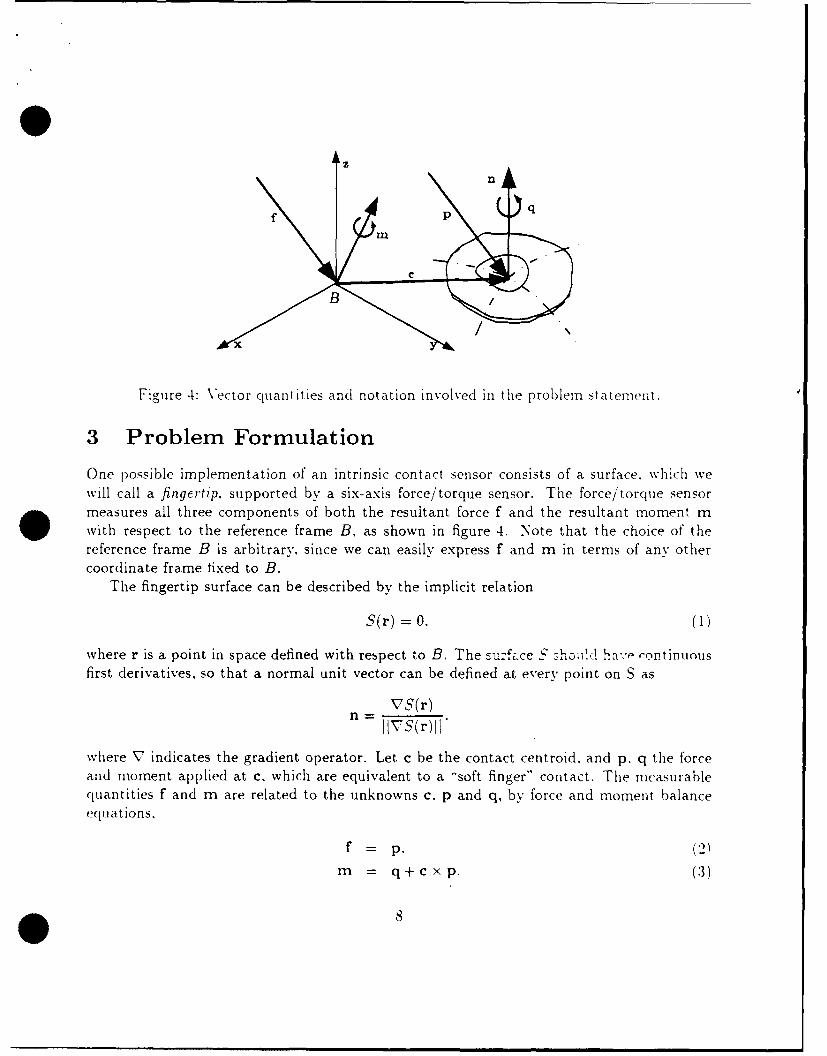
Figure 4: Vector quantities and notation involved in the problem statement.
3 Problem Formulation
One possible implementation of an intrinsic contact sensor consists of a surface. which wewill call a fingertip. supported by a six-axis force/torque sensor. The force/torque sensor. measures all three components of both the resultant force f and the resultant moment mwith respect to the reference frame B, as shown in figure 4. Note that the choice of thereference frame B is arbitrary, since we can easily express f and m in terms of any othercoordinate frame fixed to B.
The fingertip surface can be described by the implicit relation
S(r) =0, (1)
where r is a point in space defined with respect to B. The surfa.ce S shoii!d hi-., ,ontinuousfirst derivatives, so that a normal unit vector can be defined at every point on S as
VS(r)n- IIVS( r) I I
where V indicates the gradient operator. Let c be the contact centroid. and p. q the forceand moment applied at c. which are equivalent to a "soft finger" contact. The measurablequantities f and m are related to the unknowns c. p and q, by force and moment balanceequations,
f =p, (2)
m = q+cxp. (3)
For soft finger contacts the torque q is parallel to the unit vector n normal to the suirface atthe contact centroid c. hence N -
n q - - .5(c). ,
for some constant I'.\Ve call the above set of relations the cont at .-e FIS11., pohlt Tri:
Given the measurements f and n. along with a surface equation = U. ie-termine the location of the contact centroid(s) C. and the related contact force pand moment(s) q.
Note that, because of the definition of contact centroid. we implicitly require that p iscompressive, i.e. directed into the surface. and that q is normal to S. Expanding equations Ithrough 4 yields a non-linear system of ten equations in ten scalar unknowns. i.e. the nine"corp~onents of p. q, c, and A. [-owever. by simply substituting equations 2 and 4 irf
equation 3. the problem is reduced to four equations in four unknowns. Since the problemis non-linear, we need to determine if a solution exists, and in that case if it is unique.
In general. not much can be said about the existence of solutions: given arbitrary f. M.and S. there is no guarantee we can find an equivalent soft finger contact. A solution exists.however, if tile resultant force f and and moment m are measurements consistent with theeffects of a soft-finger type traction distribution on S.
If a solution exists. the following proposition holds about its uiiqueness:
Proposition 2: Uniqueness of Solutions
A solution to the contact sensing problem is unique (if it exists). if and only ifthe sensor surface is convex (see proof in Appendix 2).
Proposition 1 gives conditions on A and S that guarantee the existence of a contactcentroid. According to proposition 2, th,, contact centroid of a compressive distribution Aon a convex surface is also unique.
As a final remark, the solution to equations I through 4 may not be trivial and a closed-form solution may not be found except for the simplest surfaces. In the following sections,we will present three methods for solving these equations: first the simple point contactsolution , next the ellipsoidal solution and finally a general iterative solution.
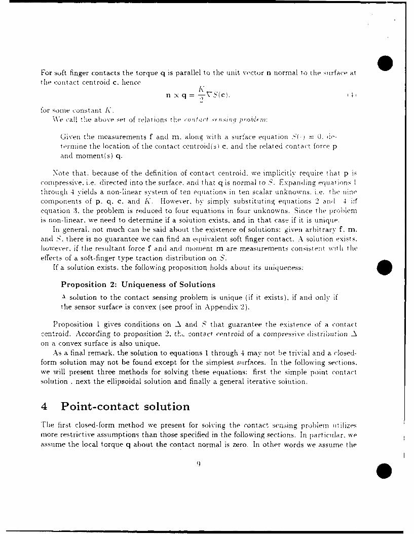
4 Point-contact solution
The first closed-form method we present for solving the contact sensing problem ltilizes
more restrictive assumptions than those specified in the following sections. In particular. weassume the local torque q about the contact normal is zero. In other words we assume the
9@

,ontact model is a point contact with friction. as described in section 2. This assurmption
can lead to good results and a simple solution for a large number of pract ical ca es. Fle
wr' nc axis of the force system is gliven !
r= r, -- \ f.
f <rn .
The wrench axis is a line through ro and parallel to f. parameterized by A. This lineintersects the convex surface S in at most two locations: one corresponding to a force pullingout of the surface and one corresponding to a force pushing into the surface. Since we donot allow adhesive forces, we can determine the contact centroid as the intersection pOint.
for which the contact force is directed into the surface, that is
fTnIc) < 0. '7)
Vhen the local torque q is not zero, the point found by this method differs from thecontact centroid. Therefore we will denote with c' the vector found using this so-called"wrench-axis' or "'point-contact") method.
Note that the assumption q = 0 can be checked out directly from force/torque measure-
ments by means of the equivalent relationship frm = 0. We should point out that the point
c' does not have any of the properties of contact centroids. so that it could in principle lie far
away from the actual location of the contact area. Yet, point c' retains a valuable meaningin real conditions as an easy- to-compute approximation of the contact centroid. In orderto give an estimate of the distance between c' and the contact centroid c. let e representthe difference vector e = c' - c. The two sets of forces and torques, p. q applied at c. and
p. t applied at c'. are both equivalent with the actual set of contact forces. hence they areequivalent with each other. The balance equation of moments about c can be written as
q = t + e x p.
Such a vector equation is solved by any e of the form
(q - t) x pe-+p SIIpiI'
Recalling that. from the definition of wrench axis. t is parallel to p. and that. by tiedefinition of contact centroid. q is normal to the surface. we can rewrite equation as
q p + t p
* 10

where Pt = p - (pTn)n is the tangential (friction) component of the contact resultant force.:rIce the error vector e is the sum of two mutually orthogonal vectors, its length is at least
as !ar(e as:
> 14 !P4
hi %'iew of this result. it can be observed that. when the local torque q is not zero. t:hedi:tance between the point found by the wrench-axis method and the contact centroid growsquickly as friction increases. Thus. the approximation of the contact centroid with point c'should be avoided if high-friction and/or compliant materials are employed in building thefingertips. Numerical examples are provided in the discussion section.
5 Solution for Ellipsoidal Surfaces
The main advantage of the wrench-axis method is that the contact location problem isreduced to that of finding the intersections of a line with a surface. that is, to elemen-tarv geometry. However, this method has two major drawbacks: first, it does not provideinformation about the moment exerted through a soft-finger contact. and second, it onlyapproximate,; the contact centroid when q is not zero. In this section we solve the contactsensilig problem and avoid such shortcomings. However, in order to guarantee a closed-formalgorithm and to simplify calculations, the fingertip surface will be restricted to belong to aspecific class of surfaces, namely, quadratic forms of the type
S(r) = rTATAr - R' = 0. (9)
where A is a constant coefficient matrix, and R is a scale factor used for convenience. Sincethe reference frame B can be moved arbitrarily, we can assume without loss of generalitythat A can be written in diagonal form /a 0 0)
A= 0 1/3 0 )0 0 /
In order to guarantee the uniqueness of solutions, the surface specification must be furtherrestricted to convex portions of the quadratic form (for instance, one of the sheets of adouble hyperboloid would be an appropriate sensor surface). In the interest of simplicity.however, we will consider in the following only general ellipsoids (i.e.. positive definite Amatrices). In this case. the principal axes of the ellipsoid are given by 20R. 23R and 2. R.with 0 < 1/a < 1. 0 < 1/3 < 1, 0 < 1/7 < 1.
It should be noted that ellipsoids are important for several reasons. First. ellipsoids ap-proximate, up to the second order. any continuous convex surface. Second, very common
| | 1| |'

surfaces. such as spheres, cylinders. and planes. can be regarded as limiting cases of an ellip-soid. Finally. the ellipsoid assumpt*on is standard in contact mechanics (e.g. the llertziantheory of elastic contact).
Substituting equation 9 into equation 4 yields
A 2cn - x q = NA 2 c. I01
and substituting this and equation 2 in equation 3, we obtain
m = KA 2 r + r x f. (II)
Equations 9 and 11 form a system of four non-linear equations and four unknowns whichcan be rewritten in the form
rc = m (12)cTA 2C = p 2. (13)
where r = F(K) is a 3 x 3 matrix whose elements are functions of K and of the measuredforce components fl, f,, and f3,
r(K) = 1a fK32 fl •f2 -f K/ 'r2
The determinant of r(K) is given by
det ['(K)= K(K2 D 2 + JIAf 12 ),
where D = det A. The matrix "(K) is singular for K = 0, i.e. when the local torque q
is zero. In this case (which can be detected by the simple equivalent condition fTm = 0.as already mentioned), the contact centroid can be determined exactly by the wrench-axismethod. The value of the parameter A in equation 5 corresponding to the intersection of thewrench-axis with the ellipsoid surface is given by
f'T/ - V(fTr' )2 - lif'll 2 (llr'II 2 - R2)
where f' = Af and r' = Ar 0 (recall the definition of r0 in equation 6).Whenever f'm # 0, [(K) has an inverse r-'(K) such that, by sol'ng equation 12 for
c, we obtain
* 12

1
c = r-im A72 i2 D'A- 2m + K(A 2f) X m+ (fT m)f. (14)det r'
By substituting equation 14 into equation 13. a scalar equation in the only unknown. K. isobtained as
cTA 2c = R 2 =K 4D4 IIA-1mrII' + l Ix IIA(A 2f x m)112 + (fTm)2(IAfl12 + 2K 2 D2 )
IK2 (K 2D2 + IAf 112)2
For such a 6-th order equation a closed-form solution should not be expected in general.due to Galois' theorem. For the particular surface assumed, though. we observe that
JIA(A 2f x m)L2 = D2 [IIA-'m112IIAfI12 - (fTm)2.
so that equation 15 can be simplified in a biquadratic equation as
IK4 D2 R2 + K 2 [R2llAf1I2 - D2 1A-1mI2j - (fTm) =0.
Only one of the four possible K solving this equation is real and consistent with thehypothesis of non-adhesive contact, and is given by
- sign(f + o 2 -4D2R2(fTm)2 , (16)vI2" R v/.D 1+(6
where
= D 2 IA-'mll2 - R2 IIAfM 12,
and
-1, for x<0
sign(x)= 0 for x=01, for x>0
By substituting K back into equation 14 and equation 10, we obtain the complete solutionfor c and q, respectively.
5.1 Particular CasesWe will now develop solutions for some particular cases of practical importance, namely the
sphere, cylinder and plane.
13

5.1.1 Sphere
For a spherical sensor surface of radius R centered at the origin of the force/torque referenceframe B. the matrix A equals the identity 13, and D = 1. Hence.
K -sign(fTm) /
--)' V /0/ + ?4R2 (fTm) 2 .
where ,' = JIl1 2 - R2lfil}.The contact centroid location (for nonzero K) is given by
1( + 1 [Krm + Kf x m + (fTm)f],K(K2 + 11]f I I)
whereas, for K = 0, the contact centroid is found using equation 5 with
A 1 R2 ]If
5.1.2 Cylinder. Consider a cylinder having the axis parallel to the z axis of the sensor frame B, and circularcross section of radius R. Such surface can be described as the limit case of an ellipsoid withcharacteristic matrix given by
0 0)
A=( 0 1 00 0 1-
for -f' -+ zo. Applying the same limit to equation 16, we have:
-fTmK= RillflII[- Irn~III2
where f± = (fi, f2, 0)T is the component of f normal to the cylinder axis, and m" =
(0-0, m 3 )T is the component of n parallel to the same axis. If K = 0, the wrench method(equation 5) should be applied. Otherwise, the contact centroid on the cylindrical surface ofthe fingertip is given by:
1ic =f 2i [K2 m '' + Kf' x mn + (fTm)f].
.. . . ..* 14m m n N I imlIlll l

5.1.3 Plane
An ellipsoid with matrix A of the form
0/r 00A ( 1 /Z, 0
, 0 0 1
degenerates, for o - o.. in a couple of parallel planes perpendicular to the x axis of B. at adistance ±R from the origin. Iff" = (0, 0, f 3 )T is the contact force component parallel thez axis, equations 16 and 14 become
-fTm
RIIf"''I
and
1C l (f x m + R 1If"11 f).
It should be noted that the last formula holds even with K = 0.
6 Iterative solution
The final method for solving the contact sensing problem is valid for any surface specifi-cation, but requires an iterative algorithm to be used at each sensor sampling time. Thecomputational efficiency of the algorithm is therefore of utmost importance for real-timeapplications.
As customary when dealing with the numerical solution of vector multivariate functions,we rewrite the problem equations in the relaxation-method form
g(x) = 0, (17)
where:
xT = (x,X 2,X 3 . x4 ) T = (c T,' K /2);gT(x) = (g1(x),g2(x),g 3 (x),g 4(x))T ,
g1(x) = x 4 VS 1 - f 2 x 3 + f 3 X2 - M1;
g2(x) = x 4 VS 2 - f 3 x1 + fIx 3 - 1712:
g3(x) = X4 VS 3 - fIx 2 + f 2xI - n 3 ;
g4(x) = S(XI,X 2 ,X3 ).
15

Standard algorithms (see e.g. [Dahliquist and Bj6rk, 1974]) for the iterative solution ofsuch equations can be applied, perhaps the most notable being the Newton-Raphson method
or its variations. The Jacobian matrix G associated with the problem can be evaluated as
G(x)-=99- X 4 H f VS
. 7- 0s) - _O
where H is the Hessian of the surface S (that is. the matrix Hi ij 1.2.:3:). and
f s is the cross-product matrix of f, such that foc = f x c.
Computing G can be more or less time consuming, depending upon the comple',;it: of thesurface S. Computing G - 1, as required by the Newton-Raphson method, can be inconvenientfor real time applications. Furthermore, in this specific case, we have that G is singular forX4 =K/2 = 0, that means that this algorithm would present serious problems whenever thecontact load has very little local torque q.
It must be noted that, in general, the numerical solution of vector multivariate nonlinearequations is not a -'nice" problem (see the related comments in [Press et al., 1988]): betteralgorithms are available for finding the extrema of multivariate scalar functions. A possibleapproach to the design of an algorithm for solving equation 17 is therefore to embed theroot-finding problem in a minimization one.
Since the Jacobian matrix G is not symmetric (its upper left minor is the sum of asymmetric and a skew-symmetric matrix), g cannot be simply regarded as the gradient of
*s some energy-like function to minimize. However, if we consider the equation
GTg(x) = 0,
we have that all the zeroes of g are also zeroes of Grg, and GTg is the gradient ('poten-tial field") associated with the positive definite scalar function V = IgTg, whose absoluteminimum is our solution.
Applying the well-known gradient descent updating law to the k-th estimate of x, wehave
X(k+l) = X(k) - AVV(x) = X(k) - AG()g(k).
We observe that the application of this gradient descent technique to minimize an energy-like (Liapunov) function V = OT(q)O(q) is equivalent to the closed-loop inverse kinematicscheme proposed by Balestrino. De.lIaria and Sciavicco [19841 and several others. to invertthe nonlinear kinematic relationship of a robot, 6(q). It can be shown with a Liapunovargument that this method is locally asymptotically convergent to the desired solution, forappropriate choices of A: and, in fact. it is intuitive that for A (i.e. step lengths) shortenough in the steepest descent direction the V function will be always kept decreasing untila minimum is reached. A discussion on the optimal choice of A has been provided by Das.Slotine and Sheridan [1989].
* 16

0 R8.7mrn
Figure 5: The fingertip sensors of the Salisbury Robot Hand are composed of a hemispherejoined to a cylinder.
The local asymptotic convergence of the algorithm means, in our current application, thatthe correct contact point will be found provided that the initial guess is "'close enough". Inorder to avoid that for arbitrary initial guesses and for some force/torque readings f. m, thealgorithm gets "stuck" at some point that does not solve the problem, it would be desirableto assess a more general global asymptotic convergence. Unfortunately, the technique ofembedding the root-finding problem in a minimization one is prone to generate such localminima, and some do exist in our specific problem even for surfaces as simple as spheres.From a practical point of view those "false" roots are easily recognized (their residues ggTare not zero). Moreover, if the algorithm is used to continuously track a contact whichchanges its position and force components with continuity (i.e. it is rolling or sliding acrossthe sensor), starting the search from the previously obtained solution is very likely to leadto the actual solution.
7 Compound surfaces
Many applications of intrinsic contact sensing use surfaces more complex than the simplegeometries described above. However, the methods presented above can be extended easilyto compound surfaces made of simpler surfaces if the compound surface is convex and thecomponent surfaces share the same normal at their boundaries. For example, the fingertipsensors of the Salisbury Robot Hand are composed of a hemisphere joined to a cylinderof equal radius, as depicted in figure 5. A solution for a compound surface is typicallyfound by trial and error: the contact centroids corresponding to the given load and to thecomplete ellipsoids to which the basic patches of the compound surface belong, are calculatedin succession: by virtue of the uniqueness property of contact centroids, the search can bestopped as soon as a contact centroid lying on the actual sensor surface is found.
If the sensor surface has sharp points, as the example depicted in figure 6. a normaldirection cannot be defined at those points and the above discussed solution methods are
17

F/T Sensor
Figure 6: A compound sensor surface with corners and edges.
not applicable directly. If the sensor or the object surfaces are compliant, this problem isnot a major concern, since surface edges are -'smoothed" out. and the properties of thecontact centroid guarantee that a meaningful result will be achieved anyway. However. ifa rigid contact occurs on a sharp point of the sensor surface. no local torque is exerted:therefore, any point found by intersecting the wrench axis with the different surface patchesshould coincide with the actual contact point. Since, in general. only noisy measurements areavailable, it may happen that no contact centroid actually lying on the sensor surface is found.In this case, a good approximation can be assumed to be the point on the sensor surfaceclosest to the calculated centroids. The worst case is when a whole edge of the sensor surfaceis in contact with the object. Since local torques can be exerted, and no normal direction isdefined, both methods discussed above would fail. However. the practical relevance of suchcases is negligible.
More complex surfaces that do not comply with the above assumptions of convexity andregularity can be dealt with in some cases. For example, a typical manipulator arm is com-posed of individually convex surfaces, but is not convex as a whole (see figure 7). Ebermanand Salisbury [1989] discussed the use of joint torque measurements to infer informationabout contacts occurring on the last link of the robot. On the other hand, a force/torquesensor at the base of the manipulator would sense contacts on any link, but would not beable to distinguish among them. By the use of both base force/torque sensing and jointtorque sensing it is conceivable to realize a fully sensorized robot surface. A -'whole hand"manipulation system, employing intrinsic contact sensors in each phalanx of its three fingersand in the palm, has been designed, and a prototype finger built, as reported by Vassuraand Bicchi [1989].
IsI

Joint TorqueSensors
F/T Sensors
Figure 7: Fully-sensorized robot arm can be constructed in principle using only force/torquemeasurements.
8 Discussion and Numerical Results
In this paper we presented material on the mathematics and mechanics of intrinsic contactsensing. The paper's main contributions are perhaps the introduction of the concept ofcontact centroid along with the proof of its geometric properties, and the presentation ofmathematical methods for computing its location on a sensor surface. In this section we willbriefly elaborate on these themes, to underscore some interesting aspects.
The interest of the contact centroid for characterizing soft fingers contacts follows from itsproperty of being located inside the convex hull enclosing every contact point. To illustratethis, a simple numerical example will be worked out. Assume that the real pattern of contacton the surface of a spherical sensor is comprised of only four points cl .... c 4, located on topof the sphere as shown in figure 8, and let ±6 and ±86 be the coordinates along the x-axisof points c1 , c3, c2, and c4 respectively.
Let the local contact forces exerted at these points be h, = (-hf. hf. -1).h2 = (-hf, hf,-1), h3 = (hf, hf, -1), and h 4 = (hf, hf, -1), respectively. Table I givesthe x-coordinates of the contact centroid c (calculated through the algorithm proposed insection 5) and of the point-contact method point c' (section 4) corresponding to differentvalues of 6 and h1 .
As can be seen, the two results diverge as the distance 6 and the friction force hf increase.Note also that for large values of 6 the contact centroid retains the characteri:'ic. 34' remaiing

hSide View Top View
hC Cl 2~ : .5 .0.1 c~ 0.02
0.0 Cr:.1 C0.7
0. C: 0.05 C'M 0.010 c, :10.00
Table~~~ 1: Positio of, the0 co t c.cn r id c a d f t e p r xi a e ( r n h- s me h d
point~c. c'00 alon th:0.i0o0dffrnvleso 5 and hf . 03
X 2,0 .2 c':65

Wrench-Axis Ellipsoid IterativeMethod Method Method
Execution time 232±6 psec 486±13 itsec 473±13 psecc/step
Fable 2: ('orput ation times for the three algorithms to solve the contact probllef un asphere. The iterative method takes an average of 20 steps to converge under to an error ofless than one part in 106 error when input data are slowly varying.
inside the contact points, while the point obtained by the point-contact method does not.Another important advaptage of the intrinsic contact sensing method is its ability to
calculate the local torque originated from friction forces. The importance of these localtorques in fine manipulation operations by robot hands has been often underestimated. T,appreciate their role, consider how humans can hold a stick horizontally by pinching it atone end between two fingertips (with a gripping force of ION, the fingers can typically resista torque of 40Nmm and a vertical weight of 5N).
The computational efficiency of the solution algorithms is of paramount importance inreal-time applications of intrinsic contact sensing. In table 2 we report computation timesfor the same surface, a sphere centered in the origin. The algorithms described in section4.5 and 6 have been implemented and timed in a real-time environment running on a Mo-torola 68030 processor with a Motorola 68881 numeric coprocessor. Note that the iterative Walgorithm is inferior to the other solutions, which are both fast enough to be claimed real-time. Another weakness of the iterative method is that the multiple solutions of equation 17cannot be discriminated in advance of their actual computation. The iterative algorithmis then recommended only for finding a complete solution for non-ellipsoidal surfaces (e.g.paraboloids) for which closed-form exact methods are not available.
To conclude the comparative analysis of the proposed algorithms, it must be noted thatthe exact method of section 5 is also preferable to the wrench-axis algorithm from a numericalstability point of view. In fact, as the formulation of the problem in terms of minimizationof a quadratic error function given in section 6 shows, the contact problem is intrinsicallystable. This is not true of the approximation that disregards local torques. Table 3 showshow small perturbations on the inputs (the force/torque sensor readings f and m) reflect insmall perturbation in the calculated contact point for the method of section 5. while theycan lead to inconsistent (complex) results for the wrench-axis method.
Devices based on the force-based contact sensing approach have been actually imple-mented. and effectively employed in robotic hands. For a discussion on the realizationof force/torque sensors on small robot fingertips, see [Brock and Chiu. 1985], and [Bicchi19871. The latter paper discusses the application of optimal design techniques to minia-turized force/torque sensors; this approach is expanded in a more thorough treatment in
21 i
Met hod Wrench- Axis Ellipsoid [ Itorative
f = L-0.3 -.04 0.011m = r0 .0 1 0.01 0.4 . c' = -0.0 )O 0.00] c = -0.60 0.80 0.001 c = [-0.60 0.'0 0.00
f = '-0 .3 -.0-1 0 .0 1 1,f = [0.01 0.0 1 1 c' = '-0.66 0.75 0.001 c = -0.66 0.75 0.041 c = '-0.66 0.75 0.041
f = [-0.3 -.04 0.01]m = [0.01 0.01 0.50 c' = [? ? ?] c = [-0.74 0.67 0.09] c = [-0.73 0.68 0.07]f = [-0.3 -.04 0.01]m = [0.01 0.01 0.51] C' = [? ? ?] c = [-0.76 0.62 0.20] c = [-0.76 0.62 0.20]
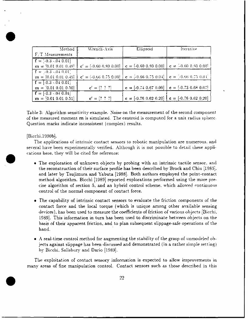
Table 3: Algorithm sensitivity example. Noise on the measurement of the second componentof the measured moment m is simulated. The centroid is computed for a unit radius sphere.Question marks indicate inconsistent (complex) results.
[Bicchi.1990b].The applications of intrinsic contact sensors to robotic manipulation are numerous, and
several have been experimentally verified. Although it is not possible to detail these appli-cations here. they will be cited for reference:
9 The exploration of unknown objects by probing with an intrinsic tactile sensor. andthe reconstruction of their surface profile has been described by Brock and Chiu [1985],and later by Tsujimura and Yabuta [1988]. Both authors employed the point-contactmethod algorithm. Bicchi [1989] reported explorations performed using the more pre-cise algorithm of section 5, and an hybrid control scheme, which allowed continuouscontrol of the normal component of contact force.
The capability of intrinsic contact sensors to evaluate the friction components of thecontact force and the local torque (which is unique among other available sensingdevices), has been used to measure the coefficients of friction of various objects [Bicchi.1989]. This information in turn has been used to discriminate between objects on thebasis of their apparent friction, and to plan subsequent slippage-safe operations of thehand.
e A real-time control method for augmenting the stability of the grasp of unmodeled ob-jects against slippage has been discussed and demonstrated (in a rather simple setting)
by Bicchi. Salisbury and Dario [1989].
The exploitation of contact sensory information is expected to allow improvements inmany areas of fine manipulation control. Contact sensors such as those described in this
99
paper can provide direct, real-time and reliable feedback of fundamental contact interactioncharacteristics. For instance, intrinsic contact sensors could be profitably used to improvethe accuracy of the control of micro-motions of manipulated objects or tools. especially illthe presence of slipping and/,'or rolling contacts.
23
References
Baiestrino. A.. De Mlaria. (-.. and Sciauicco. L. -'Robiist Control of Robotic Mani pli-
lators." P rocee(li i ,_s uf the 9t h IF.V' World Congress. vol.6. pp. S-~ 94
l~Krii .\.. r~1nu~j l~t~iper il Con)trfl) li 111 aiii pe~r Rohtt.- PhDl1.) sii I la~~I~.
Bicchi. A.:" -Intrinsic Contact Sensing for Soft Fingers." Proc. IEEE mrt. Conf.Rulbotics and Automation. Cincinnati. OH. May 1990.
Bi1cchi. A\. -'A Criterion for the Optimal Design of Multi-Axis Force Sensors." MIT AlLab Memno 1263. 199tJb.
Bicchi. A.. Dario. P.. "-Intrinsic Tactile Sensing for Artificial Hands," Proc. 4th lit.Sy-np. on Robotics Research. Santa Barbara. CA. R. Bolles and B. Roth Editors.published by the MIT Press. Cambridge, MA. 1987.
Bicchi. A.. Salisburv. J.N.. Dario, P. "'Augmentation of Grasp Robustness Using In-trinsic Tactile Sensing.' Proc. IEEE Conf. on Robotics and Automation. Scot tsdale.A\rizona. 19S9).
Brock. D.L. and Chiu. S. "'Environment Perceptions of an Articulated Robot HandU.sing Contact Sensors." Proc. ASMIE Winter Annual Meeting. Miami. FL. 19S5.
Dalilquist. G., and Bjdrk. A. "-Numerical 'Methods". Prentice Hall. 1974.
Das. H.. Slotine. J.-J.E.. and Sheridan. T.B. "Inverse Kinematic Algorithms for Re-dlundlant Systems." Proc. IEEE Int. Conf. on Robotics and Automation. Philadelphia.
Eberman. B. S. and Salisbury, J.K.: "~Determnination of Manipulator Contact Informa-tion from .Joint Torque Measurements", Experimental Robotics I. First InternationalSymposium. NMontr~al, Canada, June 1989. Published in Lecture Notes in Control andinformation Sciences. Hayward. V. and 0. Khatib (Eds.). Spninger-\'erlag. 1990.
Hunt. N.H.: "-Kinemnatic Geometry of Mechanisms." Oxford Universitv Press. London.England. 1978.
Johnson. K.L. "-Contact Mechanics-. Cambridge University Press. 198S.
Mason. NIT. andI Salisbury. .J.K. "Robot Hands and the Miechanics of Nianipuiationl."NIT Press. CI'ambridge. MIA. 1981 .
* 24
Mlinsky. NM. ~Mnp~trDesign Vignettes." MIT Al Lab Memo 267. 1972. re-issuiedas MIT A I Lab MNieo ')67A. 1981.
Nicholls. HI.R. and Lee. N.H.. --A Survey of Robot Tactile Sensing Technology.~ 1JRR .Vol 3 .. No. 3._ June . .
O kat Li. "Y.: --A New~ 1_i ti i Sensor D~esi gn B~asedI on S ipensiin- SlielIs**. in be ft 10 u.,
Robot Hands1,. Venkataraman. S.T.. and Iberall. T.. eds. Springer-Verlag. .New York.NY. 1990.
Peronneau. G.. --Position- Indicating System." US Patent Number :3.6.57.47.5. April1972.
Press. W. H.. Flannerv. B.P.. Teukolskv, S.A., Vetterling. W.T. --Numerical Recipes-.C amb~ridge I niversitv Press. I9S8.
Salisbury. .J. N., --Kinematic and Force Analysis of Robot Hands," Ph.D. Thesis. St an-f'ord Univ'ersity, 1982.
Salisbury. .J.IK.. "Interpretation of Contact Geometries from Force Measurements."Proc. 1st International .Symposium on Robotics Research. Bretton Woods. N.H..N.Brady and R.Paul Editors, published by the MIT Press, Cambridge, NIA. 1984.
Tsujilmura. T., and Yabuta, T. "Object Detection by Tactile Sensing Method employingForce/Torque Information," IEEE Transactions on Robotics and Automation. vol.5.no. 1, August 1988.
Vassura. G. and Bicchi, A.: "Whole Hand Manipulation: Design of an ArticulatedHand Exploiting All Its Parts to Increase Dexterity," in Robots and Biological Systems.N ATO-ASI Series, P.Dario. G.Aebischer, G.Sandini eds., Springer-Verlag. Berlin. RFG.19S9.
Whitney. D.E. "Historical Perspective and State of the Art in Robot Force Control."International Journal of Robotic Research, Vol. 6, No. 1, Spring 1987.
2.5

Appendix 1.
The contact centroid general property (Proposition 1) given in section 2.1 %%11 be provedin three steps. where properties of increasing generality are illustrated:
Property 1: If a distribution I of compressive contact tractions v(r), acts on aset of contact points C = {r,} of a planar surface P(r) = 0, the contact centroidof A on P lies inside the convex hull enclosing every point r, (see figure 9).
zA
B
Figure 9: Contact on a planar surface.
Proof: Consider a line p in the contact plane P passing through at least onecontact point r, and leaving all others on the same half plane, as depicted infigure 9. By definition 1, a set of forces equivalent to the given contact set iscomprised of a resultant force p = fp v(r) applied at the contact centroid, and atorque q normal to the contact plane. In order to satisfy the balance of momentsabout the line p, the contact centroid must lie on the same half plane where thecontact points do. Considering the family of all such lines p, the convex hullresults as the envelope of the family, and the proposition follows.
O 26
In other words, for a planar sensor with compressive forces, no matter how far awaythe contact points are from each other. the contact can be considered 'soft finger'. and thecontact centroid lies inside the smallest convex polygonal line enclosing every contact point.
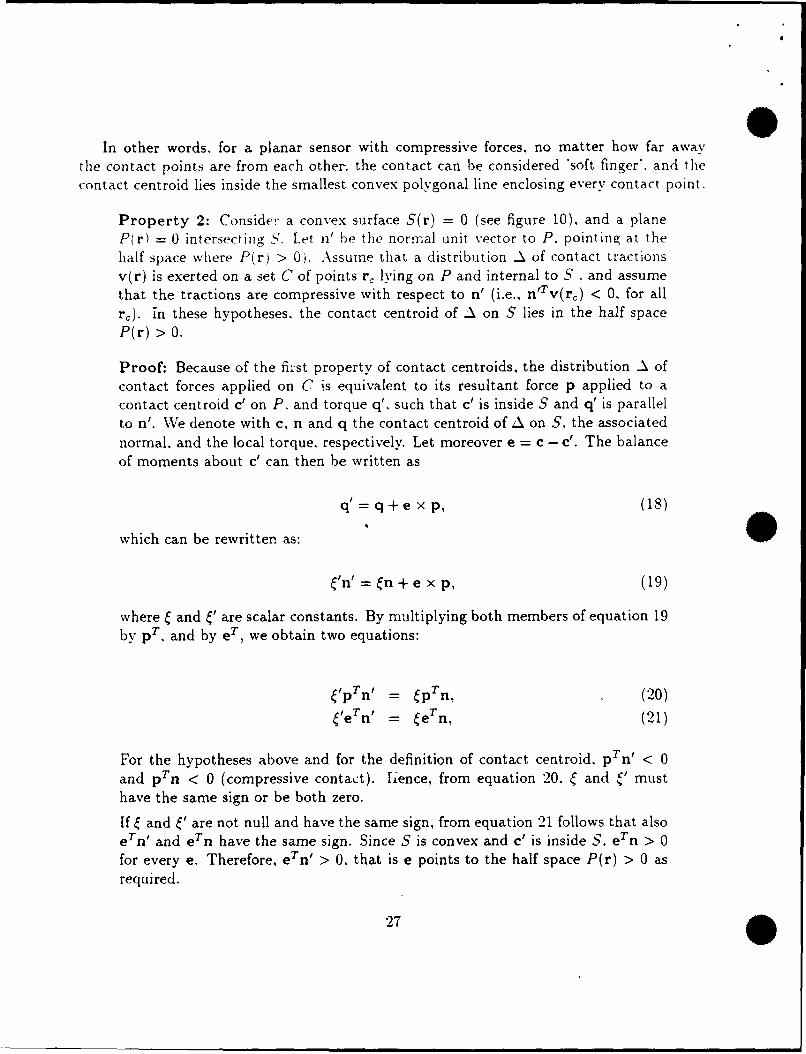
Property 2: Consider a convex surface S(r) = 0 (see figure 10). and a planeP(r) = 0 intersecting S. Let n' be the normal unit vector to P. pointing at thehalf space where P(r) > 0). Assume that a distribution A of contact tractionsv(r) is exerted on a set C of points r, lying on P and internal to S , and assumethat the tractions are compressive with respect to n' (i.e., n'Tv(rc) < 0, for allre). in these hypotheses, the contact centroid of A on S lies in the half spaceP(r) > 0.
Proof: Because of the first property of contact centroids, the distribution A ofcontact forces applied on C is equivalent to its resultant force p applied to acontact centroid c' on P, and torque q', such that c' is inside S and q' is parallelto n'. Ve denote with c, n and q the contact centroid of A on S. the associated
normal, and the local torque. respectively. Let moreover e = c - c'. The balanceof moments about c' can then be written as
= q+e x p, (18)
which can be rewritten as:
W' =n + e x p, (19)
where and ' are scalar constants. By multiplying both members of equation 19
by pT, and by eT, we obtain two equations:
'pTn' = pTn, (20)
leTn ' = eTn, (21)
For the hypotheses above and for the definition of contact centroid. pTn < 0and pTn < 0 (compressive contact). h1ence, from equation 20, ' and ,' musthave the same sign or be both zero.
If and ' are not null and have the same sign, from equation 21 follows that alsoeTn ' and eTn have the same sign. Since S is convex and c' is inside S, eTn > 0for every e. Therefore, eTn/ > 0, that is e points to the half space P(r) > 0 asrequired.
27

q& P n
e Ps
c t e Figure 10: Contact on a deformable surface.
Otherwise, if both and ' are zero, than from equation 19 follows that e and p
must be parallel. Let then e p; using again the fact that p Sn < 0 (definitionof contact centroid) and that ecan = Cprn > 0 (convexity of S), we have thatu < 0. Since also e is a contact centroid, p Tn' < 0. Finally we have thenes T n' = p n t > 0, q.e.d..
Rephrased, this second property has intuitive meaning. Consider a sensor with convex.compliant surface which is deformed by contact with a flat object: no adhesive forces areexerted, and the deformed surface stays inside the undeformed one. Since the deformedsurface is not known, the contact centroid can only be calculated relative to the sensorundeformed surface. However, the contact centroid is well behaved. in the sense that it willstay on the same side of the areas being touched (see figure 10).
Property 3: Consider a deformable body, whose undeformed surface S(r) = 0is convex, and assume that a distribution A of compressive contact tractions Isexerted on a set of contact points C = {r,) of Sq. Consider a plane P(r) -- 0 that
divides the surface of the deformed body in two portions, so that every contactpoint is confined in one half-space (see figure 2). Consider the projection of eachcontact point r, on P along the direction of the traction applied at r,: if all such
~28

projections lie inside the undeformed surface S. then the contact centroid on Sof A lies on the same side of P where A is applied.
Proof: Since pure forces or tractions can be moved along their line of applicationwithout affecting the resultant force and torque of the set. this proposition iseasily derived from property 2.
In order to give the best estimate of the location of contact points, the plane P can bechosen as the one that separates the smallest portion of S enclosing every contact point/area:if some contact points belong to P, it is required that the contact traction at those pointsbe strictly compressive with respect to the plane.
Appendix 2.
Proposition 2: Uniqueness of Solutions
A solution to the contact sensing problem, described by equations 1 through 4and by the definition of contact centroid, is unique (if it exists), if and only if thesurface is convex.
Proof: The "if" part of the proposition can be demonstrated by contradiction:assume that there are two points, c and c' (expressed in an arbitrary referenceframe B) lying on a convex surface S, that are solutions of the contact sensingproblem, and consider the vector e = c'-c (see figure 11). Because of the surfaceconvexity we have that:
e Tn > 0,eTn < 0. (22)
The balance of moments at point c can be written as
q = q + e xp,
Since q and q' are parallel to n and n' respectively, we can rewrite
n = 'n' + e x p, (23)
29

a
wp
Opce
S
Figure 11: The contact centroid on a convex surface is unique.
and, by multiplying both terms by pr, we have
prn = 'pTni,
which, since forces are assumed compressive, implies that either ' > 0 or [ =
=0.
If = ' = 0, no local torques are exerted at c nor at c', and those points lie on aline parallel to p. Because of the convexity of S, only one of the two intersectionsof such line can satisfy the definition of contact centroid (pTn < 0).
If ' > 0, by multiplying both terms of equation 23 by eT, we obtain
ern = 'eTn ',
that, together with the convexity condition 22, implies either ' < 0 (a contra-diction), or e = 0, the proposition. In addition, it can be easily shown that theuniqueness of the contact. centroid holds also if the surface is planar, providedthat the contact tractions are strictly compressive.
O30

,J i a
Figure 12: Concave surfaces may have non-unique contact centroids
To demonstrate the "only if" part, suppose the surface is not convex; that is,there exist two distinct points such that
eTn ' < 0,
eTn < 0. (24)
Thus a compressive force in the direction of e applied at either point yields*identical sets of forces and moments. Hence the solution is not unique and thestatement is proved.
31