atom cnc - eaziform.co.uk · atom cnc copyright © 2014 alex mackinnon / cde ltd. warranty this...
TRANSCRIPT

Copyright © 2014 Alex Mackinnon / CDE Ltd.
ATOM CNC

All rights reserved.
Any dispute about the use of this software and/or hardware or of these terms and conditions shall be resolved orarbitrated under English Law.
Manuals and accompanying documentation may not be copied or printed for the purposes of training, advertising,promotion or any other use without the permission of Conqueror Design and Engineering Limited.
Permission to copy and print manuals and documentation for personal use is granted to the owner/user of thesoftware supplied.
All trademarks are acknowledged to be the property of their respective owners.
This manual produced on 30/09/2014.
ATOM CNC
Copyright © 2014 Alex Mackinnon / CDE Ltd.
Warranty
This software and/or hardware and accompanying documentation are provided 'as-is' and are not warranted to be fitfor any specific purpose or usage.
The use of this software and/or hardware is undertaken at your own risk and Conqueror Design and EngineeringLimited will not be responsible for any loss of data, time or income resulting from the use of this software and/orhardware.
Warranty
Updates are available from the website.We recommend getting the latest manual updates when working with the product.

IContents
I
Copyright © 2014 Alex Mackinnon / CDE Ltd.
Table of Contents
Part 1 Introduction 1
................................................................................................................................... 11 ATOM CNC card
Part 2 Connectors (inputs & outputs) 2
................................................................................................................................... 21 VGA
................................................................................................................................... 32 Micro-SD
................................................................................................................................... 43 USB0 & USB1
................................................................................................................................... 54 Limits (or I/Os)
................................................................................................................................... 65 Buttons (or I/Os)
................................................................................................................................... 76 RS232
................................................................................................................................... 87 Encoders (or I/Os)
................................................................................................................................... 98 Motor MOT1-MOT6
................................................................................................................................... 109 MOTORS (STEPBUS)
................................................................................................................................... 1110 ANALOG
................................................................................................................................... 1211 RELAYS
................................................................................................................................... 1312 STP (safety-circuit)
................................................................................................................................... 1413 SPINDLE
................................................................................................................................... 1514 PWR (DC Supply)
Part 3 Updating firmware 16
................................................................................................................................... 171 Updating firmware using an SD card
................................................................................................................................... 182 Updating firmware using ATOM Server
Part 4 Operation 19
................................................................................................................................... 201 Setting up RS232 checksums (R005+)
Part 5 Part Programming 22
................................................................................................................................... 231 Header Section
................................................................................................................................... 252 Basic Operations
......................................................................................................................................................... 27G00 - Rapid Move
......................................................................................................................................................... 28G01 - Linear Move
......................................................................................................................................................... 29G02 - Arc Clockwise Move

ATOM CNCII
Copyright © 2014 Alex Mackinnon / CDE Ltd.
......................................................................................................................................................... 31G03 - Arc Counter-Clockwise Move
......................................................................................................................................................... 33G04 - Dwell
......................................................................................................................................................... 34G05 - Spline Function
......................................................................................................................................................... 35G06 - Cubic Spline
......................................................................................................................................................... 36G07 - Bezier Spline
......................................................................................................................................................... 37G28 - Home Axes
......................................................................................................................................................... 38G29 - Home Axes & Reset Datum
......................................................................................................................................................... 39G33 - Threading/Syncronized Move
......................................................................................................................................................... 40G34 - Synchronized Move
......................................................................................................................................................... 41Tool Nose Compensation
......................................................................................................................................................... 42G54 - Set Home/Reset Position
......................................................................................................................................................... 43G70 - Imperial Coordinates
......................................................................................................................................................... 44G71 - Metric Coordinates
......................................................................................................................................................... 45G88 - User defined cycle
......................................................................................................................................................... 46G90 - Absolute Positioning
......................................................................................................................................................... 47G91 - Incremental Positioning
......................................................................................................................................................... 48M00/01 - Stop
......................................................................................................................................................... 49M02 - Programme Stop
......................................................................................................................................................... 50M30 - Programme Stop and Rewind
......................................................................................................................................................... 51M40 - Goto label
......................................................................................................................................................... 52M41 - Goto label if input low
......................................................................................................................................................... 53M42 - Goto label if input high
......................................................................................................................................................... 54M45 - Call sub-programme
......................................................................................................................................................... 55M46 - Return from sub-programme
......................................................................................................................................................... 56M47 - Return to Programme Start / Loop
......................................................................................................................................................... 57M48- Call sub-programme if input low
......................................................................................................................................................... 58M49- Call sub-programme if input high
......................................................................................................................................................... 59M90 - Relay On
......................................................................................................................................................... 60M91 - Relay Off
......................................................................................................................................................... 61M92 - Wait for Input Low
......................................................................................................................................................... 62M93 - Wait for Input High
......................................................................................................................................................... 63M94 - Index Carousel

IIIContents
III
Copyright © 2014 Alex Mackinnon / CDE Ltd.
................................................................................................................................... 643 Lathe Operations
......................................................................................................................................................... 65G81 - Turning Cycle
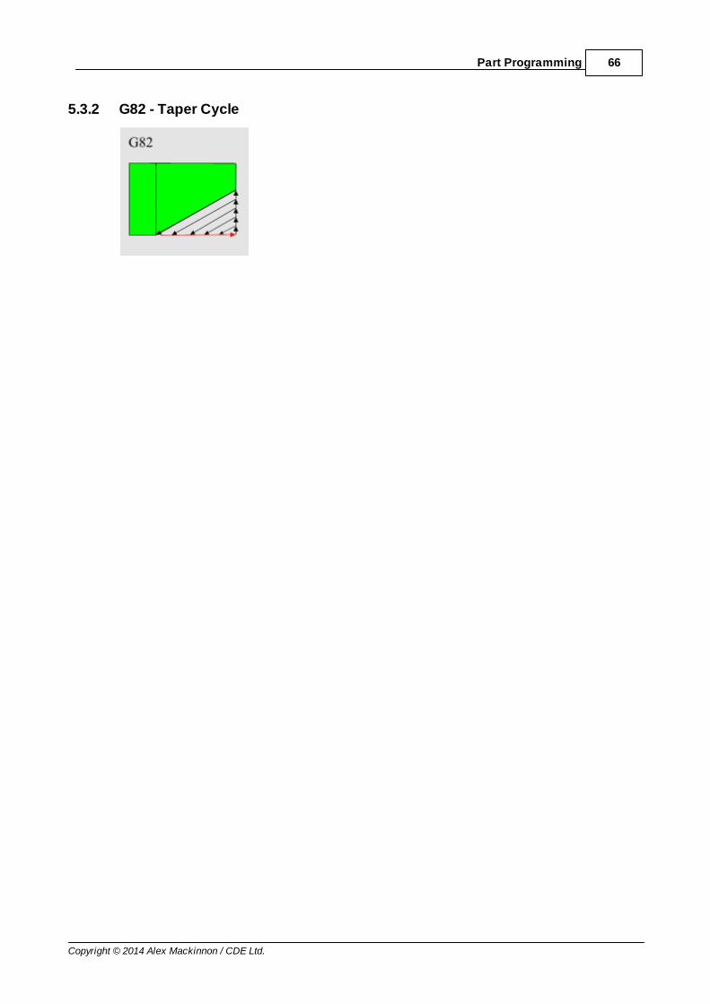
......................................................................................................................................................... 66G82 - Taper Cycle
......................................................................................................................................................... 67G83 - Arc Clockwise Cycle
......................................................................................................................................................... 68G84 - Arc Counter-Clockwise Cycle
......................................................................................................................................................... 69G85 - Facing Cycle
......................................................................................................................................................... 70G86 - Threading Cycle
......................................................................................................................................................... 71G87 - Peck Drilling Cycle
................................................................................................................................... 724 Mill Operations
......................................................................................................................................................... 73G81 - Drilling Cycle
......................................................................................................................................................... 74G82 - Peck Drilling Cycle
................................................................................................................................... 755 Mill Sample 1
................................................................................................................................... 776 Mill Sample 2
Part 6 Tool Offsets 78
................................................................................................................................... 791 Tool Offsets - Lathe
................................................................................................................................... 802 Tool Offsets - Milling Machines
Part 7 Troubleshooting 0
Part 8 Appendices 81
................................................................................................................................... 811 G-Codes
......................................................................................................................................................... 82Additional G-Codes for Lathe Operations
......................................................................................................................................................... 83Additional G-Codes for Milling Operations
................................................................................................................................... 842 M-Codes
Part 9 Control parameters 85
Index 90

1 ATOM CNC
Copyright © 2014 Alex Mackinnon / CDE Ltd.
1 Introduction
1.1 ATOM CNC card
The ATOM CNC is a multi-axis CNC controller.
2Connectors (inputs & outputs)
Copyright © 2014 Alex Mackinnon / CDE Ltd.
2 Connectors (inputs & outputs)
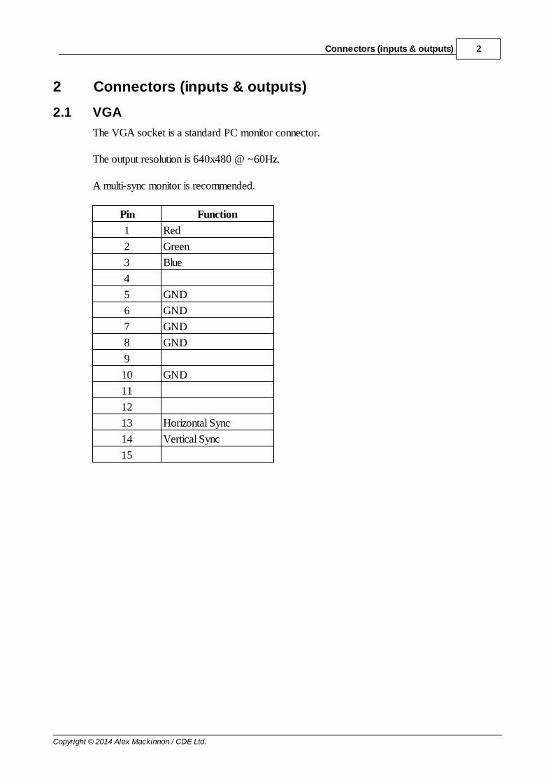
2.1 VGA
The VGA socket is a standard PC monitor connector.
The output resolution is 640x480 @ ~60Hz.
A multi-sync monitor is recommended.
Pin Function
1 Red
2 Green
3 Blue
4
5 GND
6 GND
7 GND
8 GND
9
10 GND
11
12
13 Horizontal Sync
14 Vertical Sync
15

3 ATOM CNC
Copyright © 2014 Alex Mackinnon / CDE Ltd.
2.2 Micro-SD
Micro-SD card connector.
Cards from 1GB to 8GB are supported.
The Micro-SD card should be formatted to FAT32 before use.

4Connectors (inputs & outputs)
Copyright © 2014 Alex Mackinnon / CDE Ltd.
2.3 USB0 & USB1
The card has two standard USB 2.0 type A connectors in a stacked socket.
The bottom socket closest to the PCB is USB0 and the top socket is USB1.
For most uses USB0 and USB1 can be used interchangeably although USB0 has fasterthroughput than USB1.
Neither USB0 nor USB1 is suitable for devices that require more than 500mA of current - suchas self-powered hard disk drives.

5 ATOM CNC
Copyright © 2014 Alex Mackinnon / CDE Ltd.
2.4 Limits (or I/Os)
The limits are spread across 2x 8-pin connectors.
LIM1 connector
Pin Function
1 GND
2 LIM1
3 LIM2
4 LIM3
5 LIM4
6 LIM5
7 LIM6
8 GND
LIM2 connector
Pin Function
1 GND
2 LIM7
3 LIM8
4 LIM9
5 LIM10
6 LIM11
7 LIM12
8 GND
The limits can be set to interact with any of the 12-axis.
Unused limits can be used as general purpose inputs and outputs.

6Connectors (inputs & outputs)
Copyright © 2014 Alex Mackinnon / CDE Ltd.
2.5 Buttons (or I/Os)
KEYS connector
Pin Function
1 GND
2 KEY1
3 KEY2
4 KEY3
5 KEY4
6 KEY5
7 KEY6
8 KEY7
9 KEY8
10 GND

7 ATOM CNC
Copyright © 2014 Alex Mackinnon / CDE Ltd.
2.6 RS232
RS232 connector
Pin Function
1 TX (output)
2 RX (input)
3 GND

8Connectors (inputs & outputs)
Copyright © 2014 Alex Mackinnon / CDE Ltd.
2.7 Encoders (or I/Os)
ENC1-ENC9 connectors
Pin Function
1 5VDC
2 A signal
3 B signal
4 GND
The encoder connectors are for use with quadrature encoders.
Unused encoder inputs (the A and B signals) can be used as general purpose I/Os.

9 ATOM CNC
Copyright © 2014 Alex Mackinnon / CDE Ltd.
2.8 Motor MOT1-MOT6
MOT1-MOT6 connectors
Pin Function
1 5VDC
2 CLOCK PULSE
3 DIRECTION
4 GND
MOT1 through MOT6 can be programmed to output the clock and direction signals for any ofthe 12-axis.
Together with the 6 motors that can be controlled via the STEPBUS connector this allows for12-axis control.

10Connectors (inputs & outputs)
Copyright © 2014 Alex Mackinnon / CDE Ltd.
2.9 MOTORS (STEPBUS)
MOTORS connector
Pin Function
1 5VDC
2 GND
3 XSTEP
4 YSTEP
5 ZSTEP
6 USTEP
7 DIR
8 ENABLE
9 VSTEP
10 WSTEP
The MOTORS connector is a STEPBUS connector. A STEPBUS ribbon cable can be used toeasily connect stepper motor and pseudo-stepper-motor DC servo-drives from our productrange.
An X641SC card can be used to convert the STEPBUS signals to 4x discrete step&directionoutputs (like the MOT1 through MOT6 connectors).
Together with the 6 MOT connectors this allows for 12-axis control.

11 ATOM CNC
Copyright © 2014 Alex Mackinnon / CDE Ltd.
2.10 ANALOG
ANALOG connector
Pin Function
1 5VDC
2 Analog input 1
3 Analog input 2
4 Analog input 3
5 Analog input 4
6 GND

12Connectors (inputs & outputs)
Copyright © 2014 Alex Mackinnon / CDE Ltd.
2.11 RELAYS
RELAYS connector
Pin Function
1 12VDC
2 SPINDLE
3 12VDC
4 COOLANT
5 12VDC
6 AUX1 (INT)
7 12VDC
8 AUX2
9 12VDC
10 AUX3
11 12VDC
12 AUX4
13 12VDC
14 AUX5
15 GND
The relay outputs are sink drives. A relay or other load is connected to the 12VDC supply pinand to the relevant output (pin 2, 4, 6, 8, 10, 12 or 14). When turned on the output pin willconduct to ground.
The SPINDLE, COOLANT and AUX1 outputs are interlocked with a hard-wired safety circuit(the STP connector) so that if the circuit between pins 1 and 2 of the STP connector isinterrupted the relays will turn off.

13 ATOM CNC
Copyright © 2014 Alex Mackinnon / CDE Ltd.
2.12 STP (safety-circuit)
STP connector
Pin Function
1 SAFETY #1
2 SAFETY #2
The SPINDLE, COOLANT and AUX1 outputs are interlocked with a hard-wired safety circuit(the STP connector) so that if the circuit between pins 1 and 2 of the STP connector isinterrupted the relays will turn off.
A series of components such as emergency stop buttons and cover or guard switches can beconnected in series across pins 1 and 2.

14Connectors (inputs & outputs)
Copyright © 2014 Alex Mackinnon / CDE Ltd.
2.13 SPINDLE
SPINDLE connector
Pin Function
1 Analog positive supply
2 Analog signal
3 Analog negative supply
4 Spindle on signal (+ve)
5 Spindle on common (-ve)
The ATOM CNC has an optically isolated analogue output for spindle speed control and anisolated switch for spindle on/off control.
The optically isolated analogue output is suitable for use with cards that either have provision fora DC signal to control the speed or use a low-current potentiometer to set the speed. It is notsuitable for thyristor type controllers which pass a substantial part of the motor current throughthe potentiometer or for controllers which use an AC signal to set the speed. Most DC speedcontrols and AC/3-phase inverters are compatible with the circuit.
The spindle on/off function is for use with those speed control cards which have a low-voltage,low-current logic signal for enabling the motor. If a voltage higher than 24-volts or a current morethan 40 milli-amps needs to be switched then a relay connected to the spindle relay output (seeRELAYS) will need to be used.

15 ATOM CNC
Copyright © 2014 Alex Mackinnon / CDE Ltd.
2.14 PWR (DC Supply)
PWR connector
Pin Function
1 DC supply positive
2 DC supply negative /GND
The ATOM CNC card requires a DC supply of between 12 and 40 volts.
There is a small '+' marker on the PCB next to the input for the positive supply line.

16Updating firmware
Copyright © 2014 Alex Mackinnon / CDE Ltd.
3 Updating firmware
The ATOM CNC has built-in software which is called firmware because it is installed directly onthe card.
The firmware version can be checked by selecting 'Help->About' from the menu...
The version can also be checked from within EaziCNC 3 by selecting 'Settings->Configure'. Thefirmware time and date are shown as the second and third items along the bottom of theconfiguration window...
In order to update the firmware you will require either an SD memory card or a serial connectionto a Windows computer and the firmware file which can be downloaded from our website.
In order to update the firmware using an SD card see the section ' Updating firmware using anSD card'.
In order to update the firmware using the ATOM Server software see the section ' Updatingfirmware using ATOM Server'.
It is only necessary to update the firmware if you require newer features that arereleased in later versions or in order to fix any bugs or issues that may arise.
The boot-loader software on the ATOM card will check the firmware image before installing itso there is no danger that you will load the wrong firmware file.

17 ATOM CNC
Copyright © 2014 Alex Mackinnon / CDE Ltd.
3.1 Updating firmware using an SD card
You will require...A Micro-SD card between 1GB and 8GB in size formatted to FAT32A Windows computer with a Micro-SD card reader or a USB Micro-SD adaptorThe firmware file (the latest firmware file can be downloaded from the website - http://www.eaziform.co.uk/index.php?downloads,downatom)
Update procedure...1. Download the firmware file from the website to the Windows computer2. If the firmware file is in a zip file then unzip it as the 'ATOMCNC.ROM' file is required3. Insert the Micro-SD card (use an adaptor if required) into the computer4. If the Micro-SD card is not formatted then format it to FAT32 (the SD card does not need to
be erased)5. Copy the firmware file ('ATOMCNC.ROM') to the root directory of the Micro-SD card6. Eject the Micro-SD card from the computer7. Insert the Micro-SD card into the ATOM CNC8. Power on the ATOM CNC
The firmware should update automatically.
18Updating firmware
Copyright © 2014 Alex Mackinnon / CDE Ltd.
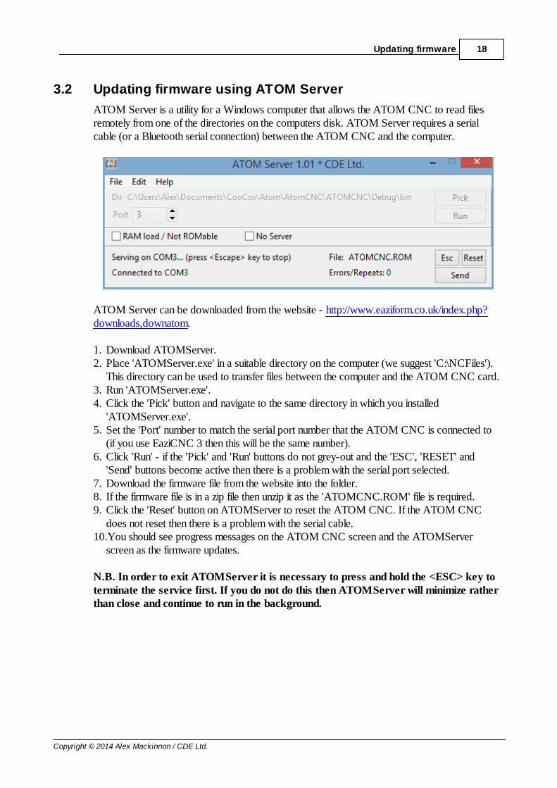
3.2 Updating firmware using ATOM Server
ATOM Server is a utility for a Windows computer that allows the ATOM CNC to read filesremotely from one of the directories on the computers disk. ATOM Server requires a serialcable (or a Bluetooth serial connection) between the ATOM CNC and the computer.
ATOM Server can be downloaded from the website - http://www.eaziform.co.uk/index.php?downloads,downatom.
1. Download ATOMServer.2. Place 'ATOMServer.exe' in a suitable directory on the computer (we suggest 'C:\NCFiles').
This directory can be used to transfer files between the computer and the ATOM CNC card.3. Run 'ATOMServer.exe'.4. Click the 'Pick' button and navigate to the same directory in which you installed
'ATOMServer.exe'.5. Set the 'Port' number to match the serial port number that the ATOM CNC is connected to
(if you use EaziCNC 3 then this will be the same number).6. Click 'Run' - if the 'Pick' and 'Run' buttons do not grey-out and the 'ESC', 'RESET' and
'Send' buttons become active then there is a problem with the serial port selected.7. Download the firmware file from the website into the folder.8. If the firmware file is in a zip file then unzip it as the 'ATOMCNC.ROM' file is required.9. Click the 'Reset' button on ATOMServer to reset the ATOM CNC. If the ATOM CNC
does not reset then there is a problem with the serial cable.10.You should see progress messages on the ATOM CNC screen and the ATOMServer
screen as the firmware updates.
N.B. In order to exit ATOMServer it is necessary to press and hold the <ESC> key toterminate the service first. If you do not do this then ATOMServer will minimize ratherthan close and continue to run in the background.

19 ATOM CNC
Copyright © 2014 Alex Mackinnon / CDE Ltd.
4 Operation

20Operation
Copyright © 2014 Alex Mackinnon / CDE Ltd.
4.1 Setting up RS232 checksums (R005+)
Firmware version R005 supports RS232 checksums when connected to EaziCNC 3.0.10 (405)or later software.
No configuration of the ATOM CNC is required to use the checksum option (other thanupgrading to R005 or later firmware) but the option does need to be configured within EaziCNC3.
1. Within EaziCNC 3 select 'Settings->Options' from the ribbon menu...
2.Select the 'Advanced Settings' tab and check the 'Enable block checksums' option.
3. Close the dialogue box by clicking the <OK> button. The 'MDI' box on the main statusdisplay should change from grey to black to indicate the programme is in checksum mode...

21 ATOM CNC
Copyright © 2014 Alex Mackinnon / CDE Ltd.
EaziCNC 3 will now send a checksum with each block of code. The ATOM CNC checks theincoming code checksum and if there is an error it requests that EaziCNC 3 send the blockagain. After 10 retries EaziCNC 3 will flag an error to the user.
If you have a monitor connected to the ATOM CNC you can see the checksums at the end ofeach line of code as an asterisk (*) followed by the decimal checksum.

22Part Programming
Copyright © 2014 Alex Mackinnon / CDE Ltd.
5 Part Programming
Part programmes consist of a header section, which defines the machine-type, material size,origin and home-position, and a sequence of CNC operational codes (G&M codes) whichcontrol the machine tool.
N.B. Even when using the CADCAM module to create programmes a header section is stillrequired to set machine-type, material, etc.
CNC operational codes fall into 2 broad categories... G-codes and M-Codes.
The distinction is sometimes obscure but generally G-codes affect or control the action of thecutting tool and M-codes change the operating characteristics of the machine tool.
For instance a G00 - Rapid Move controls the cutting tool by specifying where it moves towhereas a G41 - Tool-nose compensation Left-of-Line affects the cutting tool position too(although in a less direct way) by modifying where the tool moves to. G-codes are traditionallywritten as a 'G' with two numeric digits, i.e. "G00" but it is perfectly acceptable to write just "G0"on modern machine tools... provided that the code can be expressed with a single digit.
An M03 - Spindle Start Clockwise changes the state of the machine tool by starting the spindlemotor... this has no direct affect on the positioning of the cutting tool but it obviously hasconsiderable affect upon the cutting tool action. As with G-codes, M-codes are traditionallywritten as an 'M' with two numeric digits, i.e. "M03" but it is perfectly acceptable to write just"M3" on modern machine tools... provided that the code can be expressed with a single digit!
A number of other letter codes are used to denote such things as coordinate data ("X", "Y", "Z","E"), feed rates ("F"), spindle speeds ("S"), line numbers ("N"), tool numbers ("T") and so forth.The exact data these codes represent can be dependant on the particular G-code or M-code ineffect.

23 ATOM CNC
Copyright © 2014 Alex Mackinnon / CDE Ltd.
5.1 Header Section
The programme makes use of a number of special 'comment' lines at the start of the programme.This is called the Header Section. These comments are never sent to the machine tool (andeven if they were to be they are valid ISO comments so they would be ignored).
Machine typeFor a lathe this will be...
(* LATHE)For a mill this will be
(* MILL)
MaterialFor a lathe, the diameter and length (X and Z) of the material to be shown in theemulator. For instance for 20 mm. diameter bar 30 mm. long the line would be...
(* D20.000 L30.000 stock size)
For a mill the width, depth and height (X, Y and Z respectively) of the material to beshown in the emulator. For instance for a block 30 mm. wide 20 mm. deep and 10 mm.high the line would be...
(* W30.000 D20.000 H10.000 block size)
N.B. It is usual to define the material as the working area of the job and NOT the size ofthe billet or blank. So, for instance, in the case of the lathe stock above, 30 mm. would bethe amount of stock protruding from the chuck and directly machineable. It does not makesense to define the overall size of the billet or blank because there will always be somematerial required to hold the work-piece in place.
Origin OffsetFor a lathe the default origin is the centreline of the chuck and the left end of the work-piece (the end closest to the chuck). To set the origin to the right end (furthest from thechuck) of the above 20x30mm. bar the line would be...
(* X0.000 Z30.000 origin)
For a mill the default origin is the left, front, bottom corner of the defined block. To setthe origin to the top centre of the above 30x20x10 mm. block the line would be...
(* X15.000 Y10.000 Z10.000 origin)
Home PositionThis is the position that the tool will be returned to for tool changes or if a G28 (axishome) is executed.This position is relative to the offset origin (if one is used).To set the home position on a milling machine to be 100 mm. above the origin the linewould be...
(* HX0.000 HY0.000 HZ100.000 home)
N.B. Using the File|New... option will allow you to fill in the details easily.

24Part Programming
Copyright © 2014 Alex Mackinnon / CDE Ltd.
N.B. Using the Edit|Edit Header... option will allow you to use the dialogue to adjust theheader settings for an existing programme.
N.B. If you wish to add your own comments to the start of the programme please addthem *after* the header section. See the sample programmes for an example of commentsat the start of a programme.machinable
25 ATOM CNC
Copyright © 2014 Alex Mackinnon / CDE Ltd.
5.2 Basic Operations
The following operations are common to both lathes and mills. They are the fundamental buildingblocks of CNC programmes.
G00 - Rapid MoveG01 - Linear MoveG02 - Arc Clockwise MoveG03 - Arc Counter-Clockwise MoveG05 - Spline FunctionG06 - Cubic SplineG07 - Bezier SplineG28 - Home AxisG29 - Home Axis & Reset DatumG33 - Threading/Synchronized MoveG34 - Synchronized MoveG35 - ProbeG36 - Probe and CentreG40 - Tool-nose compensation offG41 - Tool-nose compensation Left-of-LineG42 - Tool-nose compensation Right-of-LineG54 - Set Home/Reset PositionG70 - Imperial coordinatesG71 - Metric coordinatesG88 - User defined cycleG90 - Absolute positioningG91 - Incremental positioning
M00 - StopM01 - Optional StopM02 - Programme StopM03 - Spindle Start ForwardM04 - Spindle Start ReverseM05 - Spindle StopM06 - Tool ChangeM08 - Coolant OnM09 - Coolant OffM13 - Spindle Start Forward + Coolant OnM14 - Spindle Start Reverse + Coolant OnM15 - Spindle Stop + Coolant OffM30 - Programme Stop and RewindM45 - Call sub-programmeM46 - Return from sub-programmeM47 - Return to Programme Start / LoopM90 - Relay OnM91 - Relay OffM92 - Wait for Input LowM93 - Wait for Input High

26Part Programming
Copyright © 2014 Alex Mackinnon / CDE Ltd.
M94 - Index Carousel

27 ATOM CNC
Copyright © 2014 Alex Mackinnon / CDE Ltd.
5.2.1 G00 - Rapid Move
The G00 - Rapid Move command repositions the tool at the fastest feed rate possible. Rapidpositioning is only used when it is certain that the tool will not make contact with thematerial!
The destination coordinate (or displacement coordinate in incremental mode) in each axis needsto be given on the same line as the code. For instance...
G00 X10 Z30
...will move the tool tip to X10, Z30. Coordinates can be given for the X, Y, Z and U/E axis (theU and E letters both access the 4th axis). Any coordinate/axis value which is not programmed inthe move is left unaffected.
The code is modal... this means that after a G00 has been programmed and until another modalcode is encountered each line that does not contain a G-code it treated as if it contains a G00.For instance...
G00 X10 Z30X8Z28
...will move the tool tip at rapid feed to X10, Z30 then to X8 (Z30) and then to (X8) Z28.
N.B. The movement is linear... this means that each motion of each axis starts and stops atthe same time (regardless of the different distances to be traversed) and that themovement is interpolated smoothly so that the tool travels along a straight path betweenthe start and end points.

28Part Programming
Copyright © 2014 Alex Mackinnon / CDE Ltd.
5.2.2 G01 - Linear Move
The G01 - Linear Move command repositions the tool at a set feed rate.
The destination coordinate (or displacement coordinate in incremental mode) in each axis needsto be given on the same line as the code. The feed rate can be set for the move using the "F"parameter. Feed rates are modal so a G01 command without a feed rate set will use the last feedrate used in the programme. For instance...
G01 X10 Z30 F100
...will move the tool tip to X10, Z30 at a feed rate of 100 mm./min. Coordinates can be given forthe X, Y, Z and U/E axis (the U and E letters both access the 4th axis). Any coordinate/axisvalue which is not programmed in the move is left unaffected.
The code is modal... this means that after a G01 has been programmed and until another modalcode is encountered each line that does not contain a G-code it treated as if it contains a G01.For instance...
G01 X10 Z30 F100X8Z28 F50
...will move the tool tip at a feed of 100 mm./min. to X10, Z30 then to X8 (Z30) and then to(X8) Z28 at a feed of 50 mm./min.
N.B. The movement is linear... this means that each motion of each axis starts and stops atthe same time (regardless of the different distances to be traversed) and that themovement is interpolated smoothly so that the tool travels along a straight path betweenthe start and end points.

29 ATOM CNC
Copyright © 2014 Alex Mackinnon / CDE Ltd.
5.2.3 G02 - Arc Clockwise Move
The G02 - Arc Clockwise Move positions the tool to a new point by moving it along a curvedpath.
The destination coordinate (or displacement coordinate in incremental mode) in each axis needsto be given on the same line as the code. The feed rate can be set for the move using the "F"parameter. Feed rates are modal so a G02 command without a feed rate set will use the last feedrate used in the programme. The centre or curvature of the circle also needs to be set using eitherthe "R" radius parameter or the "I", "J" and "K" parameters to set the circle centre position. The"R", "I", "J" and "K" parameters are all modal. For instance...
G02 X10 Z20 F100 R20
...will move the tool in a clockwise arc of radius 20 mm. at a feed of 100 mm//min. to theposition X10, Z20.
The code is modal... this means that after a G02 has been programmed and until another modalcode is encountered each line that does not contain a G-code it treated as if it contains a G02.For instance...
G00 X5 Z30G02 X10 Z25 R5X5 Z20
...will move the tool to X5 Z30 at rapid feed (see G00 for details) then move the tool in aclockwise arc to X10 Z25 and finally move the tool in a clockwise arc to X5, Z20.
N.B. If the end point is not on the same circle as the start point and the centre or if theradius given is too small to connect the 2 points an error will be generated.
N.B. When specifying the arc using the "R" radius parameters it is only possible toprogramme moves that are less than 90º... this is because the acute arc is always chosen(the shortest arc which connects the 2 points). Using the "I", "J" and "K" parameters it ispossible to programme arcs up to 360º.
Lathe/2-axis machine
Because a lathe HAS only 2 axis (X & Z) there is no confusion about which 2 axis are tointerpolated... it is always going to be X & Z.

30Part Programming
Copyright © 2014 Alex Mackinnon / CDE Ltd.
Mill/3-axis machine
On a milling machine there are 3 potential axis combinations that the curve can be interpolatedaround... X & Y, X & Z and Y & Z. To select which axis combination is required the G17 (X &Y), G18 (X & Z) and G19 (Y & Z) codes can be used. N.B. By default the milling machine isin G17 (X & Y) mode.
There is an extended use for the G02 command when milling... the axis that are not to becircular-interpolated can be simultaneously linear interpolated... in effect what this means is that itis easy to programme simple 3D curves, such as a spiral, by specifying a displacement for thethird axis. Please see the mill sample programmes for an illustration of programming a spiralmove.

31 ATOM CNC
Copyright © 2014 Alex Mackinnon / CDE Ltd.
5.2.4 G03 - Arc Counter-Clockwise Move
The G03 - Arc Counter-Clockwise Move positions the tool to a new point by moving it alonga curved path.
The destination coordinate (or displacement coordinate in incremental mode) in each axis needsto be given on the same line as the code. The feed rate can be set for the move using the "F"parameter. Feed rates are modal so a G02 command without a feed rate set will use the last feedrate used in the programme. The centre or curvature of the circle also needs to be set using eitherthe "R" radius parameter or the "I", "J" and "K" parameters to set the circle centre position. The"R", "I", "J" and "K" parameters are all modal. For instance...
G03 X10 Z20 F100 R20
...will move the tool in a counter-clockwise arc of radius 20 mm. at a feed of 100 mm//min. tothe position X10, Z20.
The code is modal... this means that after a G02 has been programmed and until another modalcode is encountered each line that does not contain a G-code it treated as if it contains a G03.For instance...
G00 X5 Z30G03 X10 Z25 R5X5 Z20
...will move the tool to X5 Z30 at rapid feed (see G00 for details) then move the tool in acounter-clockwise arc to X10 Z25 and finally move the tool in a counter-clockwise arc to X5,Z20.
N.B. If the end point is not on the same circle as the start point and the centre or if theradius given is too small to connect the 2 points an error will be generated.
N.B. When specifying the arc using the "R" radius parameters it is only possible toprogramme moves that are less than 90º... this is because the acute arc is always chosen(the shortest arc which connects the 2 points). Using the "I", "J" and "K" parameters it ispossible to programme arcs up to 360º.
Lathe/2-axis machine
Because a lathe HAS only 2 axis (X & Z) there is no confusion about which 2 axis are to

32Part Programming
Copyright © 2014 Alex Mackinnon / CDE Ltd.
interpolated... it is always going to be X & Z.
Mill/3-axis machine
On a milling machine there are 3 potential axis combinations that the curve can be interpolatedaround... X & Y, X & Z and Y & Z. To select which axis combination is required the G17 (X &Y), G18 (X & Z) and G19 (Y & Z) codes can be used. N.B. By default the milling machine isin G17 (X & Y) mode.
There is an extended use for the G03 command when milling... the axis that are not to becircular-interpolated can be simultaneously linear interpolated... in effect what this means is that itis easy to programme simple 3D curves, such as a spiral, by specifying a displacement for thethird axis. Please see the mill sample programmes for an illustration of programming a spiralmove.

33 ATOM CNC
Copyright © 2014 Alex Mackinnon / CDE Ltd.
5.2.5 G04 - Dwell
The programme will pause for the number of seconds given in parameter S.
The programme can be restarted before the delay is over by pressing <Space>.
If this command is processed/programmed on an X-card then the delay can be set in 1/100ths ofa second as parameter R.

34Part Programming
Copyright © 2014 Alex Mackinnon / CDE Ltd.
5.2.6 G05 - Spline Function
Data points will be interpreted as a spline curve. Current supported modes are...P0 - OffP1 - Linear segmentsP2 - Cubic splineP3 - Bezier Curve
Not all modes are supported by all control cards.
It is recommended to use G06 - Cubic spline and G07 - Bezier Spline instead.

35 ATOM CNC
Copyright © 2014 Alex Mackinnon / CDE Ltd.
5.2.7 G06 - Cubic Spline
Starting point is current position, X, Y, Z, E is destination (2) and the weighted control point isA, B, C, D and P (1).
N.B. If the weight P is not used it should be set to 1.

36Part Programming
Copyright © 2014 Alex Mackinnon / CDE Ltd.
5.2.8 G07 - Bezier Spline
Starting point is current position, destination is X, Y, Z, E (3) and the 1st and 2nd control pointsare A, B, C, D and I, J, K, L respectively.
N.B. A bezier spline can reverse itself or loop if the 1st and 2nd control points arereversed.
37 ATOM CNC
Copyright © 2014 Alex Mackinnon / CDE Ltd.
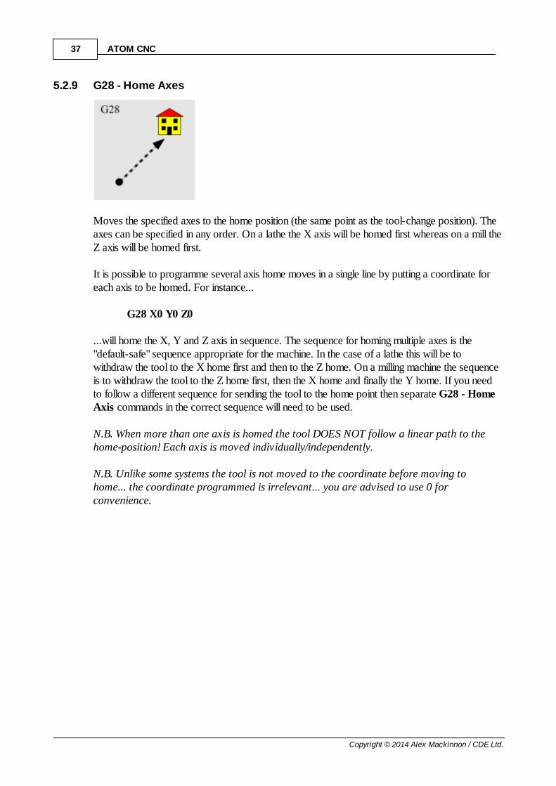
5.2.9 G28 - Home Axes
Moves the specified axes to the home position (the same point as the tool-change position). Theaxes can be specified in any order. On a lathe the X axis will be homed first whereas on a mill theZ axis will be homed first.
It is possible to programme several axis home moves in a single line by putting a coordinate foreach axis to be homed. For instance...
G28 X0 Y0 Z0
...will home the X, Y and Z axis in sequence. The sequence for homing multiple axes is the"default-safe" sequence appropriate for the machine. In the case of a lathe this will be towithdraw the tool to the X home first and then to the Z home. On a milling machine the sequenceis to withdraw the tool to the Z home first, then the X home and finally the Y home. If you needto follow a different sequence for sending the tool to the home point then separate G28 - HomeAxis commands in the correct sequence will need to be used.
N.B. When more than one axis is homed the tool DOES NOT follow a linear path to thehome-position! Each axis is moved individually/independently.
N.B. Unlike some systems the tool is not moved to the coordinate before moving tohome... the coordinate programmed is irrelevant... you are advised to use 0 forconvenience.

38Part Programming
Copyright © 2014 Alex Mackinnon / CDE Ltd.
5.2.10 G29 - Home Axes & Reset Datum
Moves the specified axis/axes to the limit switch (if fitted and enabled) and resets the datum onsome control cards. The axis can be specified in any order. On a lathe the X axis will be homedfirst and the Z second whereas on a mill the Z axis will be homed first, the Y second and the Xlast.
If the datum value is reset by the control card then the value stored by a previous G54 - SetHome/Reset Position command is used. Later cards (any V2 software M64x, the M4xx or X-series) do not reset the datum - a G92 can be used to set whatever values are required.
The axis value can be used to make an incremental move before the axis is homed.
N.B. When more than one axis is homed the tool DOES NOT follow a linear path to thehome-position! Each axis is moved individually/independently.
N.B. Unlike some systems the tool is not moved to the coordinate before moving tohome... the coordinate programmed is irrelevant... you are advised to use 0 forconvenience.
N.B. This command is only useful on machines fitted with datum-position/limit-switches.

39 ATOM CNC
Copyright © 2014 Alex Mackinnon / CDE Ltd.
5.2.11 G33 - Threading/Syncronized Move
Moves to the X, Z position given in a movement synchronized with the spindle.
The movement is synchronised to the spindle using 2 sensors - a single-pulse per revolutionsensor which makes sure that repeated calls to the G33 command start at the same spindleposition and a multi-pulse sensor which compensates for drift in the spindle speed during themovement.
The pitch (and spindle synchronization) is set by parameter P.
If X and Y values are given then they must be less than the Z value.

40Part Programming
Copyright © 2014 Alex Mackinnon / CDE Ltd.
5.2.12 G34 - Synchronized Move
Moves to the X, Y, Z position given in a movement synchronized with the spindle (or anyexternal pulse source).
The movement is synchronised to the spindle using a single sensor - a multi-pulse sensor whichcompensates for drift in the spindle speed during the movement. Unlike the G33 command themovement starting position is not synchronized to the same spindle position.
The pitch (and spindle synchronization) is set by parameter P.
If X and Y values are given then they must be less than the Z value.

41 ATOM CNC
Copyright © 2014 Alex Mackinnon / CDE Ltd.
5.2.13 Tool Nose Compensation
Tool nose radius compensation is usually used on milling machines rather than lathes, although itcan be used on either.
The diameters of the rotating cutting tools used on milling machines can vary according to toolwear and whether, in the case of high-speed-steel (HSS) or similar, they have been sharpened orre-ground. Instead of constantly changing the end-points or coordinates of the moves tocompensate for the cutter variances it is possible to programme for the centre-line of the tool andthen to use tool-nose compensation to let the machine tool adjust for the different tool size. In thisway if the cutter size varies only the value of the radius of the cutter needs to be changed in thetool offset table or in the programme to modify the code.
The two types of tool-nose cutter compensation are G41 - Tool Nose Compensation Left-of-Line and G42 - Tool Nose Compensation Right-of-Line. There is also a code for cancellingtool nose compensation for operations that really do reference the centre point of the tool... suchas drilling.
With no tool nose compensation selected the tool path will follow the points programmed... seethe left-hand picture above.
With G41 - Tool Nose Compensation Left-of-Line selected the tool will follow a path offsetto the left from the points programmed by the radius of the cutter... see the offset path in themiddle picture above. The path followed is adjusted so that it will not accidentally cross theprogrammed path... extra movements are inserted if necessary to make sure of this. Left-of-lineis most easily understood if you imagine yourself walking along with the tool... the left is your left.
With G42 - Tool Nose Compensation Right-of-Line selected the tool will follow a path offsetto the right from the points programmed by the radius of the cutter... see the offset path in theright-hand picture above. The path followed is adjusted so that it will not accidentally cross theprogrammed path... extra movements are inserted if necessary to make sure of this. As withLeft-of-line above if you imagine yourself walking along with the tool... the right is your right.
N.B. If you use tool nose radius compensation on a lathe the path is offset in the X & Zplane and not the X & Y plane as on a mill. Also the radius that you will be compensatingfor is the curvature of the tip of the tool... probably a disposable carbide tip.

42Part Programming
Copyright © 2014 Alex Mackinnon / CDE Ltd.
5.2.14 G54 - Set Home/Reset Position
Sets the Home/Reset position.
This command is only used by V1 firmware M64x cards - it is redundant and was phased out onlater cards/firmware. The axes can be sent to the limits using G29 and a G92 used to re-programme the position instead.
N.B. These values are only used with the G29 - Home Axes & Reset Datum command tore-establish a fixed datum on start-up or after a power-outage/emergency-stop.

43 ATOM CNC
Copyright © 2014 Alex Mackinnon / CDE Ltd.
5.2.15 G70 - Imperial Coordinates
After this command all coordinates are interpreted as Imperial/Inch measurements.
N.B. Using this command does not affect the current position of the tool so metric andimperial coordinates can be mixed in a programme.

44Part Programming
Copyright © 2014 Alex Mackinnon / CDE Ltd.
5.2.16 G71 - Metric Coordinates
After this command all coordinates are interpreted as Metric/millimetre measurements.
N.B. Using this command does not affect the current position of the tool so metric andimperial coordinates can be mixed in a programme.

45 ATOM CNC
Copyright © 2014 Alex Mackinnon / CDE Ltd.
5.2.17 G88 - User defined cycle
The 'G88 - User defined cycle' code executes the code provided by the user at each data-point.
The user code can contain normal NC code together with macro-commands and variables...G0 X[X1] Y[Y1]G1 Z[Z1]G0 Z[Z0]
...the sample code performs a simple drilling operation at each data-point.
Macros and variables are enclosed in square braces '[X0]'.
The available variables are...
Variable Evaluates to...
X0 Starting X coordinate (position resulting from last move)
X1 Ending X coordinate (coordinate given in command calling the cycle)
Y0 Starting Y coordinate (position resulting from last move)
Y1 Ending Y coordinate (coordinate given in command calling the cycle)
Z0 Starting Z coordinate (position resulting from last move)
Z1 Ending Z coordinate (coordinate given in command calling the cycle)
P Last P value given in programme
R Last R value given in programme

46Part Programming
Copyright © 2014 Alex Mackinnon / CDE Ltd.
5.2.18 G90 - Absolute Positioning
After this command coordinates are interpreted as absolute positions... that is distances relativeto the 0 datum set on the machine.
Coordinates can be either absolute or incremental.
Absolute coordinates are relative to the fixed 0 datum set on the machine so, for instance if thetool is positioned at X10, Y10, Z10 and the command...
G0 X5 Y5 Z5
...is given then the tool will move to X5, Y5, Z5.
Incremental coordinates are relative to the current position of the tool so, for instance, if thetool is again at X10, Y10, Z10 and the command...
G0 X5 Y5 Z5
...is given then the tool will move to X15, Y15, Z15. The coordinates are added to the existingposition.
Programmes are usually written using absolute coordinates... the reason for this is that ifincremental coordinates were used then any change to the programme will have a 'knock-on'effect through the whole programme. This 'carry-forward' effect is useful for parts ofprogrammes, such as subroutines, where writing the subroutine in the incremental coordinatesmeans that the subroutine can be called to operate relative to the starting position.
N.B. The same flexibility of incremental coordinates can be used without the moreawkward programming considerations by using a G56 - Set Temporary Origin and G55 -Cancel Temporary Origin around the code block.
47 ATOM CNC
Copyright © 2014 Alex Mackinnon / CDE Ltd.
5.2.19 G91 - Incremental Positioning
After this command coordinates are interpreted as incremental offsets to the current position.
Coordinates can be either absolute or incremental.
Absolute coordinates are relative to the fixed 0 datum set on the machine so, for instance if thetool is positioned at X10, Y10, Z10 and the command...
G0 X5 Y5 Z5
...is given then the tool will move to X5, Y5, Z5.
Incremental coordinates are relative to the current position of the tool so, for instance, if thetool is again at X10, Y10, Z10 and the command...
G0 X5 Y5 Z5
...is given then the tool will move to X15, Y15, Z15. The coordinates are added to the existingposition.
Programmes are usually written using absolute coordinates... the reason for this is that ifincremental coordinates were used then any change to the programme will have a 'knock-on'effect through the whole programme. This 'carry-forward' effect is useful for parts ofprogrammes, such as subroutines, where writing the subroutine in the incremental coordinatesmeans that the subroutine can be called to operate relative to the starting position.
N.B. The same flexibility of incremental coordinates can be used without the moreawkward programming considerations by using a G56 - Set Temporary Origin and G55 -Cancel Temporary Origin around the code block.

48Part Programming
Copyright © 2014 Alex Mackinnon / CDE Ltd.
5.2.20 M00/01 - Stop
This code will stop the programme.
The spindle and the coolant are not affected by this code and the programme can be restartedand will continue with the next programme block.
M00/M01 are used to temporarily halt a programme... for instance if the operator needs tocheck the part or to clear swarf away before the next operation then an M00 code can beinserted in the programme to pause the programme until the operator is ready.
N. B. On some machines M01 is an optional stop... there is a switch or setting on themachine tool that allows the M01 code to be selectively ignored. In this case the M00 andM01 code are identical... the programme will always be halted.

49 ATOM CNC
Copyright © 2014 Alex Mackinnon / CDE Ltd.
5.2.21 M02 - Programme Stop
This code will stop the programme.
The coolant and the spindle will be turned off (if they are on).
After this code is executed the programme cannot be restarted... the machine needs to be resetto the start of programme for execution to start again.
N. B. This code is used at the end of the main programme code. The reason that theprogramme cannot be restarted after an M02 is that the code can be used to protect codesuch as subroutines to stop it being run by accident.

50Part Programming
Copyright © 2014 Alex Mackinnon / CDE Ltd.
5.2.22 M30 - Programme Stop and Rewind
This code will stop the programme.
The coolant and the spindle will be turned off (if they are on).
After this code is executed the programme is reset to the start of programme ready for executionto start again.
N. B. This code is used at the end of the main programme code. Any programme codeafter the M30 cannot be run so the code can be used to protect code such as subroutinesto stop it being run by accident.

51 ATOM CNC
Copyright © 2014 Alex Mackinnon / CDE Ltd.
5.2.23 M40 - Goto label
Jumps to label L in the programme.
Labels can be defined as N.

52Part Programming
Copyright © 2014 Alex Mackinnon / CDE Ltd.
5.2.24 M41 - Goto label if input low
Jumps to label L in the programme if the input P is low.
Labels can be defined as N.Input codes are...
[All cards] 0 - Any key, 1 - X+ limit, 2 - X- limit, 3 - Y+ limit, 4 - Y- limit,5 - Z+ limit, 6 - Z- limit, 7 - U limit (if supported), 8 - V limit (if supported), 9 - W limit (ifsupported)
[X-Series] 7 - FB1, 8 - FB2, 9 - EXA, 10 - EXB, 11 - EYA, 12 - EYB,13 - EZA, 14 - EZB, 15 - EUA, 16 - EUB, 17 - EVA, 18 - EVB,19 - EWA, 20 - EWB, 21 - EHA, 22 - EHB, 23 - F15, 24 - F16

53 ATOM CNC
Copyright © 2014 Alex Mackinnon / CDE Ltd.
5.2.25 M42 - Goto label if input high
Jumps to label L in the programme if the input P is high.
Input codes are...
[All cards] 0 - Any key, 1 - X+ limit, 2 - X- limit, 3 - Y+ limit, 4 - Y- limit,5 - Z+ limit, 6 - Z- limit, 7 - U limit (if supported), 8 - V limit (if supported), 9 - W limit (ifsupported)
[X-Series] 7 - FB1, 8 - FB2, 9 - EXA, 10 - EXB, 11 - EYA, 12 - EYB,13 - EZA, 14 - EZB, 15 - EUA, 16 - EUB, 17 - EVA, 18 - EVB,19 - EWA, 20 - EWB, 21 - EHA, 22 - EHB, 23 - F15, 24 - F16

54Part Programming
Copyright © 2014 Alex Mackinnon / CDE Ltd.
5.2.26 M45 - Call sub-programme
Calls a sub-programme.
The sub-programme number should be given as parameter L.
Sub-programmes should be labeled with the 'O' or ':' tag, for instance 'O1' or ':1' and placedafter the programme end (M02 or M30).

55 ATOM CNC
Copyright © 2014 Alex Mackinnon / CDE Ltd.
5.2.27 M46 - Return from sub-programme
Returns from a sub-programme. Sub-programmes should end with an M46 rather than an M02or M30.

56Part Programming
Copyright © 2014 Alex Mackinnon / CDE Ltd.
5.2.28 M47 - Return to Programme Start / Loop
Restarts programme from the beginning. If an R value is given this is the repeat count and therestart will occur that number of times only.
A specific section can be looped if a P parameter is given. The P parameter should refer to an Nnumber (such as 'N10') earlier in the programme. The loop will repeat from the line *after* theline containing the N parameter.
N.B. Loops and subroutines can be nested a maximum of eight levels deep.

57 ATOM CNC
Copyright © 2014 Alex Mackinnon / CDE Ltd.
5.2.29 M48- Call sub-programme if input low
Calls a sub-programme if the input P is low.
The sub-programme number should be given as parameter L.
Sub-programmes should be labeled with the 'O' or ':' tag, for instance 'O1' or ':1' and placedafter the programme end (M02 or M30).
Input codes are...
[All cards] 0 - Any key, 1 - X+ limit, 2 - X- limit, 3 - Y+ limit, 4 - Y- limit,5 - Z+ limit, 6 - Z- limit, 7 - U limit (if supported), 8 - V limit (if supported), 9 - W limit (ifsupported)
[X-Series] 7 - FB1, 8 - FB2, 9 - EXA, 10 - EXB, 11 - EYA, 12 - EYB,13 - EZA, 14 - EZB, 15 - EUA, 16 - EUB, 17 - EVA, 18 - EVB,19 - EWA, 20 - EWB, 21 - EHA, 22 - EHB, 23 - F15, 24 - F16

58Part Programming
Copyright © 2014 Alex Mackinnon / CDE Ltd.
5.2.30 M49- Call sub-programme if input high
Calls a sub-programme if the input P is high.
The sub-programme number should be given as parameter L.
Sub-programmes should be labeled with the 'O' or ':' tag, for instance 'O1' or ':1' and placedafter the programme end (M02 or M30).
Input codes are...
[All cards] 0 - Any key, 1 - X+ limit, 2 - X- limit, 3 - Y+ limit, 4 - Y- limit,5 - Z+ limit, 6 - Z- limit, 7 - U limit (if supported), 8 - V limit (if supported), 9 - W limit (ifsupported)
[X-Series] 7 - FB1, 8 - FB2, 9 - EXA, 10 - EXB, 11 - EYA, 12 - EYB,13 - EZA, 14 - EZB, 15 - EUA, 16 - EUB, 17 - EVA, 18 - EVB,19 - EWA, 20 - EWB, 21 - EHA, 22 - EHB, 23 - F15, 24 - F16

59 ATOM CNC
Copyright © 2014 Alex Mackinnon / CDE Ltd.
5.2.31 M90 - Relay On
The relay number P is turned on.

60Part Programming
Copyright © 2014 Alex Mackinnon / CDE Ltd.
5.2.32 M91 - Relay Off
The relay number P is turned off.
If P is 99 then all relays are turned off.

61 ATOM CNC
Copyright © 2014 Alex Mackinnon / CDE Ltd.
5.2.33 M92 - Wait for Input Low
Waits for input number P to be low.
On X-series cards an optional R value can be given which is the number of 1/100ths of a secondthat the signal must be stable to be accepted.
Input codes are...
[All cards] 0 - Any key, 1 - X+ limit, 2 - X- limit, 3 - Y+ limit, 4 - Y- limit,5 - Z+ limit, 6 - Z- limit, 7 - U limit (if supported), 8 - V limit (if supported), 9 - W limit (ifsupported)
[X-Series] 7 - FB1, 8 - FB2, 9 - EXA, 10 - EXB, 11 - EYA, 12 - EYB,13 - EZA, 14 - EZB, 15 - EUA, 16 - EUB, 17 - EVA, 18 - EVB,19 - EWA, 20 - EWB, 21 - EHA, 22 - EHB, 23 - F15, 24 - F16
62Part Programming
Copyright © 2014 Alex Mackinnon / CDE Ltd.
5.2.34 M93 - Wait for Input High
Waits for input number P to be high.
On X-series cards an optional R value can be given which is the number of 1/100ths of a secondthat the signal must be stable to be accepted.
Input codes are...
[All cards] 0 - Any key, 1 - X+ limit, 2 - X- limit, 3 - Y+ limit, 4 - Y- limit,5 - Z+ limit, 6 - Z- limit, 7 - U limit (if supported), 8 - V limit (if supported), 9 - W limit (ifsupported)
[X-Series] 7 - FB1, 8 - FB2, 9 - EXA, 10 - EXB, 11 - EYA, 12 - EYB,13 - EZA, 14 - EZB, 15 - EUA, 16 - EUB, 17 - EVA, 18 - EVB,19 - EWA, 20 - EWB, 21 - EHA, 22 - EHB, 23 - F15, 24 - F16

63 ATOM CNC
Copyright © 2014 Alex Mackinnon / CDE Ltd.
5.2.35 M94 - Index Carousel
Indexes the rotary carousel by 1 tool position.
The forward and reverse delays (or steps) are set using parameter 21.

64Part Programming
Copyright © 2014 Alex Mackinnon / CDE Ltd.
5.3 Lathe Operations
The following operations are only relevant to a lathe.
G33 - Threading/synchronised cutG81 - Turning CycleG82 - Taper CycleG83 - Arc Clockwise CycleG84 - Arc Counter-Clockwise CycleG85 - Facing CycleG86 - Threading Cycle

65 ATOM CNC
Copyright © 2014 Alex Mackinnon / CDE Ltd.
5.3.1 G81 - Turning Cycle
66Part Programming
Copyright © 2014 Alex Mackinnon / CDE Ltd.
5.3.2 G82 - Taper Cycle

67 ATOM CNC
Copyright © 2014 Alex Mackinnon / CDE Ltd.
5.3.3 G83 - Arc Clockwise Cycle

68Part Programming
Copyright © 2014 Alex Mackinnon / CDE Ltd.
5.3.4 G84 - Arc Counter-Clockwise Cycle

69 ATOM CNC
Copyright © 2014 Alex Mackinnon / CDE Ltd.
5.3.5 G85 - Facing Cycle

70Part Programming
Copyright © 2014 Alex Mackinnon / CDE Ltd.
5.3.6 G86 - Threading Cycle
Z sets the thread length, X sets the thread depth and P is the thread pitch.
The thread will be created in a series of passes. The depth of each pass can be set as I and afinal finish depth can be set as A. Alternatively the required number of passes can be given as Rand progressive cuts will be calculated.
R is limited to 200. If you set an R value higher than 200 then 200 will be used.
NB. Tapered threads cannot be cut using the canned cycle... use a series of G33 movesinstead.

71 ATOM CNC
Copyright © 2014 Alex Mackinnon / CDE Ltd.
5.3.7 G87 - Peck Drilling Cycle
Drills holes using a pecking cycle (drill part way, retract and then continue drilling).
The R parameter is the depth to rapid to before starting drilling. The P parameter is the peckdepth.
Z is the hole depth. The drill will rapid back to the starting Z after drilling.

72Part Programming
Copyright © 2014 Alex Mackinnon / CDE Ltd.
5.4 Mill Operations
The following operations are only relevant to a milling machine.
G17 - Interpolation in X&Y planeG18 - Interpolation in X&Z planeG19 - Interpolation in Y&Z planeG46 - Orient U to X&YG81 - Drilling CycleG82 - Peck Drilling CycleG83 - Tapping CycleG84 - Boring CycleG85 - Pocketing Cycle

73 ATOM CNC
Copyright © 2014 Alex Mackinnon / CDE Ltd.
5.4.1 G81 - Drilling Cycle
Drills holes.
The R parameter is the depth to rapid down to before starting drilling.
Z is the hole depth. The drill will rapid back to the starting Z after drilling.
R and the hole depth are modal UNLESS a G81 is present on the line.

74Part Programming
Copyright © 2014 Alex Mackinnon / CDE Ltd.
5.4.2 G82 - Peck Drilling Cycle
Drills holes using a pecking cycle (drill part way down, retract and then continue drilling).
The R parameter is the depth to rapid down to before starting drilling. The P parameter is thepeck depth.
Z is the hole depth. The drill will rapid back to the starting Z after drilling.

75 ATOM CNC
Copyright © 2014 Alex Mackinnon / CDE Ltd.
5.5 Mill Sample 1
(* MILL) selects a milling machine as the target for theprogramme
(* W20.000 D20.000 H10.000 block size) sets the material block size to 20x20x10 mm.(* X0.000 Y0.000 Z10.000 origin) sets the programme origin to the front, left, top
corner of the block(* HX0.000 HY0.000 HZ10.000 home) sets the home position to be 10 mm. above the
origin( MILL SAMPLE #1 ) no '(*' so just a commentM3 S1000 starts the spindle and sets the speed to 1000
RPMG0 X5 Y10 F200 moves the tool to X5, Y10 and sets the feed rate
to 200 mm./min.M8 starts the coolantG0 Z1 I6 J10 K11 moves the tool to 1 mm. above the block topG1 Z-2 drills the tool into the block 2mm. deepG2 X10 Y15 R5 moves the tool in a clockwise arc (of radius 5) to
X10, Y15G2 X15 Y10 R5 moves the tool in a clockwise arc (of radius 5) to
X15, Y10G2 X10 Y5 R5 moves the tool in a clockwise arc (of radius 5) to
X10, Y5G2 X5 Y10 R5 moves the tool in a clockwise arc (of radius 5) to
X5, Y10G1 Z0 moves the tool up (at feed) to the top of the
block (Z0)G0 Z1 moves the tool up (rapidly) to 1 mm. above the
blockG0 X1 Y-1 moves the tool (rapidly) to X1, Y-1G1 Z-3 drills the tool into the block to Z-3G2 X2 Y0 R1 moves the tool in a clockwise arc (of radius 1) to
X2, Y0G1 X18 moves the tool (at feed) to X18G3 X20 Y2 R2 moves the tool in a counter-clockwise arc (of
radius 2) to X20, Y2G1 Y18 moves the tool (at feed) to Y18G3 X18 Y20 R2 moves the tool in a counter-clockwise arc (of
radius 2) to X18, Y20G1 X2 moves the tool (at feed) to X2G3 X0 Y18 R2 moves the tool in a counter-clockwise arc (of
radius 2) to X0, Y18G1 Y2 moves the tool (at feed) to Y2G3 X2 Y0 R2 moves the tool in a counter-clockwise arc (of
radius 2) to X2, Y0G2 X3 Y-1 R1 moves the tool in a clockwise arc (of radius 1) to
X3, Y-1G1 Z1 moves the tool (at feed) to Z1

76Part Programming
Copyright © 2014 Alex Mackinnon / CDE Ltd.
G28 X0 Y0 Z0 moves the tool to the home position at X0, Y0,Z10
M2 stops the programme

77 ATOM CNC
Copyright © 2014 Alex Mackinnon / CDE Ltd.
5.6 Mill Sample 2
(* MILL) selects a milling machine as the target for theprogramme
(* W20.000 D20.000 H10.000 block size) sets the material block size to 20x20x10 mm.(* X0.000 Y0.000 Z10.000 origin) sets the programme origin to the front, left, top
corner of the block(* HX0.000 HY0.000 HZ10.000 home) sets the home position to be 10 mm. above the
origin( SPIRAL DEMO ) no '(*' so just a commentM3 S1000 starts the spindle and sets the speed to 1000
RPMG0 X5 Y10 F200 moves the tool (rapidly) to X5, Y10 and sets
the feed to 200 mm./min.Z1 moves the tool (rapidly) to 1mm. above the
block (Z1)G1 Z-2 drills the tool down 3mm. (to Z-2)G3 X10 Y5 Z-4 R5 spirals the tool counter-clockwise to X10, Y5
plunging 2 mm.G3 X15 Y10 Z-6 R5 spirals the tool counter-clockwise to X15, Y10
plunging 2 mm.G3 X10 Y15 Z-8 R5 spirals the tool counter-clockwise to X10, Y15
plunging 2 mm.G3 X5 Y10 Z-10 R5 spirals the tool counter-clockwise to X5, Y10
plunging 2 mm.G1 Z0 moves the tool (at feed) to the top of the block
(Z0)G28 X0 Y0 Z0 moves the tool to the home position at X0, Y0,
Z10M2 stops the programme

78Tool Offsets
Copyright © 2014 Alex Mackinnon / CDE Ltd.
6 Tool Offsets
Tool offsets are required when a programme needs to use more than one physical tool in a partprogramme. For instance on a lathe a special tool may be required to create threads or to part-off the finished part, or, on a milling machine, a drill may be required to drill holes and a slot-drillor end mill to cut a profile or pocket.
In some circumstances it might be possible to mount the tools so that they share a commonreference point but in most cases that is impractical because the tools have radically differentshapes or cutting characteristics. That is where tool offsets are useful... a tool offset is theinformation the system needs to continue the NC programme with a different tool withoutneeding to reset the basic part datum. The actual information in the tool offset varies - somepeople use an absolute datum and reference all tools from that but a more common method is touse a master or datum tool and to reference all other tools from that tool. The master/datum toolcan be a cutting tool or a setting device (such as a 'wobbler').
The tool offsets are stored in the tool offset table...
...you can access the offset table from the emulation or machining modes by pressing the <F11>key.
The table stores an X, Y and Z offset for each tool, the tool description can be changed and adiameter (for use with milling cutters and the tool-nose-radius compensation codes) can also bestored.

79 ATOM CNC
Copyright © 2014 Alex Mackinnon / CDE Ltd.
6.1 Tool Offsets - Lathe
If three lathe tools are to be used, 1, 2 and 3, and are mounted in holders which fit in the sametool post then the tips will have their datum in three different places (see illustration above).
In order to use these tools in the same programme you need to enter the differences between thedatum for tools 2 and 3 from the reference tool 1.
Suggested procedure for settings tool offsets...
The following procedure is suggested for setting the tools offsets. If this procedure is followedthen the tools may be preset to the master tool (which in this case will be tool 0 - the defaulttool). In order to use a different sized billet it will only be necessary to reset the master datum fortool 0... because all other tools are relative to tool 0 they will still have correct offsets.
1. Place a billet in the chuck of the lathe and load tool 0.2. Using the manual controls face the billet and set the Z datum to 0 (using <F8>).3. Turn a section of the billet and set the X datum to 0 (using <F6>).4. Load another tool.5. Using the manual controls move the tool until the tip is either touching or is parallel to the face
of the part.6. Press <F11> and enter the Z coordinate shown on the screen as the Z offset for the loaded
tool.7. Using the manual controls move the tool until the tip is touching the outside diameter of the
turned section or is parallel to it.8. Press <F11> and enter the X coordinate shown on the screen as the X offset for the loaded
tool.9. Repeat steps 4 through 8 for each of the tools requiring an offset.
You might like to change the tool name to something descriptive in the tool table when takingoffsets.

80Tool Offsets
Copyright © 2014 Alex Mackinnon / CDE Ltd.
6.2 Tool Offsets - Milling Machines
If three milling tools, 1, 2, and 3 are to be used then, if they are different lengths or types, it islikely that although the X and Y coordinates will be the same for each tool the Z will be different.
Suggested method for setting the tool offsets...
1. Load the default tool (tool 0) into the milling machine.2. Using the manual controls move the tip of the tool to a known position (a slip of paper or a
gauge block can be useful - the tool can be brought down onto a work-piece or the top of afixture with the paper or block in between, it is not necessary to have the spindle poweredyou just move the Z slowly until it grips the paper or block).
3. Set the Z datum to zero using <F8> (if a piece of paper or gauge block was used then makesure to use the same for all other tools).
4. Load another tool.5. Using the manual controls again move the Z down to the known position (or until it grips the
paper or block).6. Press <F11> and enter the Z coordinate shown on the screen as the Z offset for the tool.7. Repeat steps 4 through 6 for the other tools.
The offsets for all tools should be set at the same X & Y position so, if possible, avoid movingthe X & Y when taking offsets.
You might like to change the tool name to something descriptive or to store the tool diameter inthe tool table when taking offsets.

81 ATOM CNC
Copyright © 2014 Alex Mackinnon / CDE Ltd.
8 Appendices
8.1 G-Codes
G-Code Parameters Description
G00* X, Y, Z, E Rapid Move
G01* X, Y, Z, E, F Feed Move
G02* X, Y, Z, E, I, J, K, F, R Arc Clockwise Move
G03* X, Y, Z, E, I, J, K, F, R Arc Counter-Clockwise Move
G04 S Dwell. S=Seconds to delay.
G05* P Spline function (Bezier curve) (only available whenrunning with the ATOM CNC software)
G06 X, Y, Z, E, A, B, C, D, P Cubic Spline (with weight)
G07 X, Y, Z, E, A, B, C, D, I, J, K, L
Bezier Spline
G17 - Use XY plane for circular interpolation (Top)
G18 - Use XZ plane for circular interpolation (Front)
G19 - Use YZ plane for circular interpolation (Side)
G28 X, Y, Z, E Home Axes
G29 X,Y,Z,E Home Axes & Reset Datum
G33 X,Y,Z,P Threading/Synchronized Move
G34 X,Y,Z,P Synchronized Move
G40 - Tool-nose compensation off (default mode)
G41 R Tool-nose compensation Left-of-Line
G42 R Tool-nose compensation Right-of-Line
G43 - Tool-length compensation (positive)
G44 - Tool-length compensation (negative - default mode)
G45 - Cancel Tool-length compensation.
G54 X, Y, Z, E Set home/reset position.
G70 - Imperial coordinates (only available when runningwith the ATOM CNC software)
G71 - Metric coordinates (default mode)
G90 - Absolute coordinates (default mode)
G91 - Incremental coordinates (only available whenrunning with the ATOM CNC software)
G92 X, Y, Z, E Set datum point.N.B. The E axis can also be programmed as U.N.B. The codes marked with * are modal. Modal codes are active on any subsequent linesthat do not have a code given.

82Appendices
Copyright © 2014 Alex Mackinnon / CDE Ltd.
8.1.1 Additional G-Codes for Lathe Operations
G-Code Parameters Description
G33 X, Z, P, I Threading(/synchronized) cut. P is pitch, I is endpull-out in X.
G80 - Cancel Canned Cycle
G81* X, Z, P Turning cycle
G82* X, Z, P Taper cycle
G83* X, Z, I, K, R, P Arc Clockwise Cycle
G84* X, Z, I, K, R, P Arc Counter-Clockwise Cycle
G85* X, Z, P Facing Cycle
G86* X, Z, P, I, K, R Threading(/synchronized) cut cycle. X is pass offset(pass depth). P is pitch, I is end pull-out, K is passoffset in Z and R is number of passes.
G94 - Feed rates in mm./in. per minute
G95 - Feed rates in mm./in. per spindle revolution
G96 - Constant surface speed.Feed rate specified in mm. at 20.0 mm. diameter.Feed rate specified in inches at 1.0 inch diameter.
N.B. The E axis can also be programmed as U.N.B. The codes marked with * are modal. Modal codes are active on any subsequent linesthat do not have a code given.

83 ATOM CNC
Copyright © 2014 Alex Mackinnon / CDE Ltd.
8.1.2 Additional G-Codes for Milling Operations
G-Code Parameters Description
G50 - Mirror Off. Cancel any mirrored axis.
G51 X, Y, Z, E Mirror. Mirror selected axis (around coordinategiven).
G55 - Offset Off. Cancel/Clear temporary origin
G56 X, Y, Z, E Offset. Set temporary origin.
G80 - Cancel/Complete Canned Cycle.
G81* Z Drill, Spot-Drill
G82* Z, K Peck Drill
G83* Z, P Tapping
G84* Z Bore
G85* Z, P Pocket cycle.N.B. The E axis can also be programmed as U.N.B. The codes marked with * are modal. Modal codes are active on any subsequent linesthat do not have a code given.

84Appendices
Copyright © 2014 Alex Mackinnon / CDE Ltd.
8.2 M-Codes
M-Code Parameters Description
M00 - Stop
M01 - Optional Stop
M02 - Programme Stop
M03 S Spindle Start Clockwise
M04 S Spindle Start Counter-clockwise
M05 - Spindle Stop
M06 R, T, X, Y, Z Tool Change
M08 - Coolant On
M09 - Coolant Off
M13 S Spindle Start Clockwise + Coolant On
M14 S Spindle Start Counter-clockwise + Coolant On
M15 - Spindle Stop + Coolant Off
M30 - Programme Stop and Rewind
M45 L Call sub-programme. L is sub-programme label.
M46 - Return from sub-programme
M47 R, P Return to Programme Start / LoopR is the repeat count (if given). P is label (if given).
M90 P Relay P On
M91 P Relay P Off
M92 P Wait for input P to be Low
M93 P Wait for input P to be High
M94 - Index tool-post. Indexes the tool-post (if fitted)forward.
M98 - Motor Drives On
M99 - Motor Drives Off

85 ATOM CNC
Copyright © 2014 Alex Mackinnon / CDE Ltd.
9 Control parameters
Parameter Type Description
0 Binary Configuration 1 -bit 0 - X axis directionbit 1 - Y axis directionbit 2 - Z axis directionbit 3 - U axis directionbit 4 - X axis home directionbit 5 - Y axis home directionbit 6 - Z axis home directionbit 7 - U axis home directionbit 9 - turn off motors when idlebit 10 - reservedbit 11 - reservedbit 12 - reservedbit 13 - Relay 4 is reserved for motorreversebit 14 - tool carousel on motor Ubit 15 - reservedbit 16 - Enable hand-wheel to be used forfeed-rate override
1 Binary Configuration 2 -bit 0 - reservedbit 1 - reservedbit 2 - reservedbit 3 - reservedbit 4 - X limits activebit 5 - Y limits activebit 6 - Z limits activebit 7 - U limits activebit 8 - X limit positive is NC (normallyclosed)bit 9 - X limit negative is NC (normallyclosed)bit 10 - Y limit positive is NC (normallyclosed)bit 11 - Y limit negative is NC (normallyclosed)bit 12 - Z limit positive is NC (normallyclosed)bit 13 - Z limit negative is NC (normallyclosed)bit 14 - U limit positive is NC (normallyclosed)bit 15 - U limit negative is NC (normallyclosed)

86Control parameters
Copyright © 2014 Alex Mackinnon / CDE Ltd.
2 Integer Minimum Spindle Speed. Default=200RPM
3 Integer Maximum Spindle Speed. Default=2000RPM
4 Integer Maximum Cutting Feed Rate. Default=400mm./min.
5 Integer Rapid Feed Rate. Default=800 mm./min.
6 Integer Pulses/Revolution on Threading/Synchronizing Encoder. Default=360[Setting this to 0 will cause the slots to becounted]
7 Integer Default Circular Interpolation Mode.0=XY, 1=XZ, 2=YZ.
8 Integer X-scale (X-step size in millimetres = (P9/P8)/P19)
9 Integer X-divisor (X-step size in millimetres = (P9/P8)/P19)
10 Integer Y-scale (Y-step size in millimetres = (P11/P10)/P19)
11 Integer Y-divisor (Y-step size in millimetres =(P11/P10)/P19)
12 Integer Z-scale (Z-step size in millimetres = (P13/P12)/P19)
13 Integer Z-divisor (Z-step size in millimetres =(P13/P12)/P19)
14 Integer E/U-scale (E-step size in millimetres =(P15/P14)/P19)
15 Integer E/U-divisor (E-step size in millimetres =(P15/P14)/P19)
16 Integer Scalar for Feed rates. Steps/sec=625,000*P17/(Feed*P16).
17 Integer Divisor for Feed rates. Steps/sec=625,000*P17/(Feed*P16).
18 Integer Decimal digits in coordinates. Default=3digits
19 Integer Divisor for coordinates. Default=1000
20 Binary Low byte - Control capabilities. Do notalter!High-byte - X, Y and Z axis mapping
21 Integer Delays for carousel tool post.Forward delay = (low byte + 1)*0.25secsReverse delay = (high byte + 1)*0.25 secs[For stepper driven carousels 32768 (highbit) + steps/100. Reverse is half of

87 ATOM CNC
Copyright © 2014 Alex Mackinnon / CDE Ltd.
forward steps]
22 Integer Time-out for manual mode and automaticmotor turn-off.Default value is 2344 which gives a 5minute delay.Delay in seconds = (P22 * 32) / pull-in-rate
23 Integer Ramp stages (Maximum 16)
24 Integer Ramp 0
25 Integer Ramp 1
26 Integer Ramp 2
27 Integer Ramp 3
28 Integer Ramp 4
29 Integer Ramp 5
30 Integer Ramp 6
31 Integer Ramp 7
32 Integer Ramp 8
33 Integer Ramp 9
34 Integer Ramp 10
35 Integer Ramp 11
36 Integer Ramp 12
37 Integer Ramp 13
38 Integer Ramp 14
39 Integer Ramp 15
40 Integer Back-lash compensation for X axis (steps)
41 Integer Back-lash compensation for Y axis (steps)
42 Integer Back-lash compensation for Z axis (steps)
43 Integer Back-lash compensation for E/U axis(steps)
44 Integer Back-lash compensation for V axis (steps)
45 Integer Back-lash compensation for W axis(steps)
46 Integer V-scale (V-step size in millimetres = (P47/P46)/P19)
47 Integer V-divisor (V-step size in millimetres =(P47/P46)/P19)
48 Integer W-scale (W-step size in millimetres =(P49/P48)/P19)
49 Integer W-divisor (W-step size in millimetres =(P49/P48)/P19)
50 Integer X-encoder scale (scale=low-byte,divisor=high-byte)
51 Integer Y-encoder scale (scale=low-byte,divisor=high-byte)

88Control parameters
Copyright © 2014 Alex Mackinnon / CDE Ltd.
52 Integer Z-encoder scale (scale=low-byte,divisor=high-byte)
53 Integer U-encoder scale (scale=low-byte,divisor=high-byte)
54 Integer V-encoder scale (scale=low-byte,divisor=high-byte)
55 Integer W-encoder scale (scale=low-byte,divisor=high-byte)
56 Integer Number of steps to retract from limit aftera G29
57 Integer Enable/disable feedback for axes. Bits...[15-6 reserved][5 - W][4 - V][3 - U][2 -Z][1 - Y][0 - X]
58 Integer Low-byte - encoder gap (0..15)High-byte - encoder error limit(0=ignored/try-forever)
59 Integer Sync signal control for VGA monitor (0 bydefault)
60 Binary Control capabilities (read-only)bit 0 - uses raw-stepsbits 1-3 - reservedbit 4 - supports U&V (6-axis)bit 5 - supports feedback (closed-loop)bits 6-15 - reserved
61 Integer Processor clock speed in Mhz
62 -
63 -
64 -
65 Integer Low-byte - steps/level for RAMPHigh-byte - ramp stages
66 Integer Pull-in rate for RAMP
67 Integer Peak rate for RAMP
68 -
69 -
70 Binary POS clocks for axis 0
71 Binary NEG clocks for axis 0
72 Integer Low-byte - LIMP bit #High-byte - LIMN bit #
73 Integer Low-byte - MANP key-pattern for axis 0High-byte - MANN key-pattern
74 Integer Low-byte - mask for manual keys for axis0
75-79 Axis 1
80-84 Axis 2
85-89 Axis 3

89 ATOM CNC
Copyright © 2014 Alex Mackinnon / CDE Ltd.
90-94 Axis 4
95-99 Axis 5

Index 90
Copyright © 2014 Alex Mackinnon / CDE Ltd.
Index
- D -Datum 38, 42
- E -EaziCNC 3 configuration 20
- G -G & M Codes 22
G00 - Rapid Move 27
G01 - Linear Move 28
G02 - Arc Clockwise Move 29
G03 - Arc Counter-Clockwise Move 31
G04 - Dwell 33
G05 - Spline Function 34
G06 - Cubic Spline 35
G07 - Bezier Spline 36
G28 - Home Axes 37
G29 - Home Axes & Reset Datum 38
G33 - Threading/Synchronized Move 39
G40 - Tool Nose Compensation Off 41
G41 - Tool Nose Compensation Left-of-line 41
G42 - Tool Nose Compensation Right-of-line 41
G54 - Set Home/Reset Position 42
G70 - Imperial Coordinates 43
G71 - Metric Coordinates 44
G81 - Turning Cycle (Lathe) 65
G82 - Taper Cycle (Lathe) 66
G83 - Arc Clockwise Cycle (Lathe) 67
G84 - Arc Counter Clockwise Cycle (Lathe) 68
G85 - Facing Cycle (Lathe) 69
G86 - Threading Cycle (Lathe) 70
G88 - User defined cycle 45
G90 - Absolute Positioning 46
G91 - Incremental Positioning 47
G-codes 81
- L -Lathe 81, 82
- M -M00 - Programme Stop 48
M01 - Optional Stop 48
M02 - Programme End 49
M30 - Programme End 49
M-codes 84
Mill 81, 83Mill Sample 1 75
Mill Sample 2 77
- P -Parameters 85
- R -RS232 checksums 20
- S -spirals 29, 31, 77
splines 34, 35, 36