automatic peak hour load management system
DESCRIPTION
mdkmskTRANSCRIPT

ADVANCED POWER management system (apms)
MINI PROJECT REPORT
Submitted in partial fulfillment of the requirements for the award of theBachelor of Technology degree in Electrical and Electronics engineering
Of Cochin University of Science and Technology
BY
ANAND SAURAVNEERAJ KUMAR
PRATYUSH AISHWARYAMROUSHAN KUMARSHUBHU SAURAV
PRABHASH KUMAR
DIVISION OF ELECTRICAL AND ELECTRONICS ENGINEERING
SCHOOL OF ENGINEERINGCOCHIN UNIVERSITY OF SCIENCE AND TECHNOLOGY
KOCHI-682022
DIVISION OF ELECTRICAL AND ELECTRONICS ENGINEERINGSCHOOL OF ENGINEERING

COCHIN OF UNIVERSITY OF SCIENCE AND TECHNOLOGYKOCHI-682022
2013
This is to certify that the project entitled “ADVANCED POWER MANAGEMENT SYSTEM (APMS)” is a bona fide record of the Project work done by Mr. ANAND SAURAV Mr. NEERAJ KUMAR, Mr. PRATYUSH AISHWARYAM, Mr. SHUBHU SAURAV, Mr. ROUSHAN KUMAR, Mr. PRABHASH KUMAR under our guidance towards the partial fulfillment of the requirement of B.TECH degree in Electrical and Electronics engineering of the Cochin University of Science and Technology during the year 2012-2013
Project guide Head of Department

ACKNOWLEDGEMENT
Our first experience of project has been successfully, thanks to the support of many friends and teachers with gratitude. We wish to acknowledge all of them. However, we wish to make special mention of the following. First of all, we are thankful of our project guide Mrs. SHEENA K. M. wholeheartedly thankful to her for giving us her valuable time, attention and for providing us a systematic way for completing our project in time.We must make mention of Dr. ASHA E. DANIEL, Mrs. P.G. LATHA and special thanks to our Head of Department Dr. USHA NAIR for their co-operation and assistance in solving a technical problem. We also would thank to all lab maintenance staff for providing us assistance in various h/w and s/w problem encountered during course of our project.We are also very thankful to all of our friends and classmates, who gave us an invaluable help
TABLE OF CONTENTS

CONTENT PAGE NO.
CertificateAcknowledgementOverview 6Working 7PCB Construction 8PCB layout 8Program of Microcontroller 9Circuit diagram 13Component’s list 15Load Management 16Smart grid 19Light dependent resistor 27Bridge rectifier 28Relay 29PIC Microcontroller 31Voltage regulator 37Resistor 39Capacitor 42LED 44Transistor 46

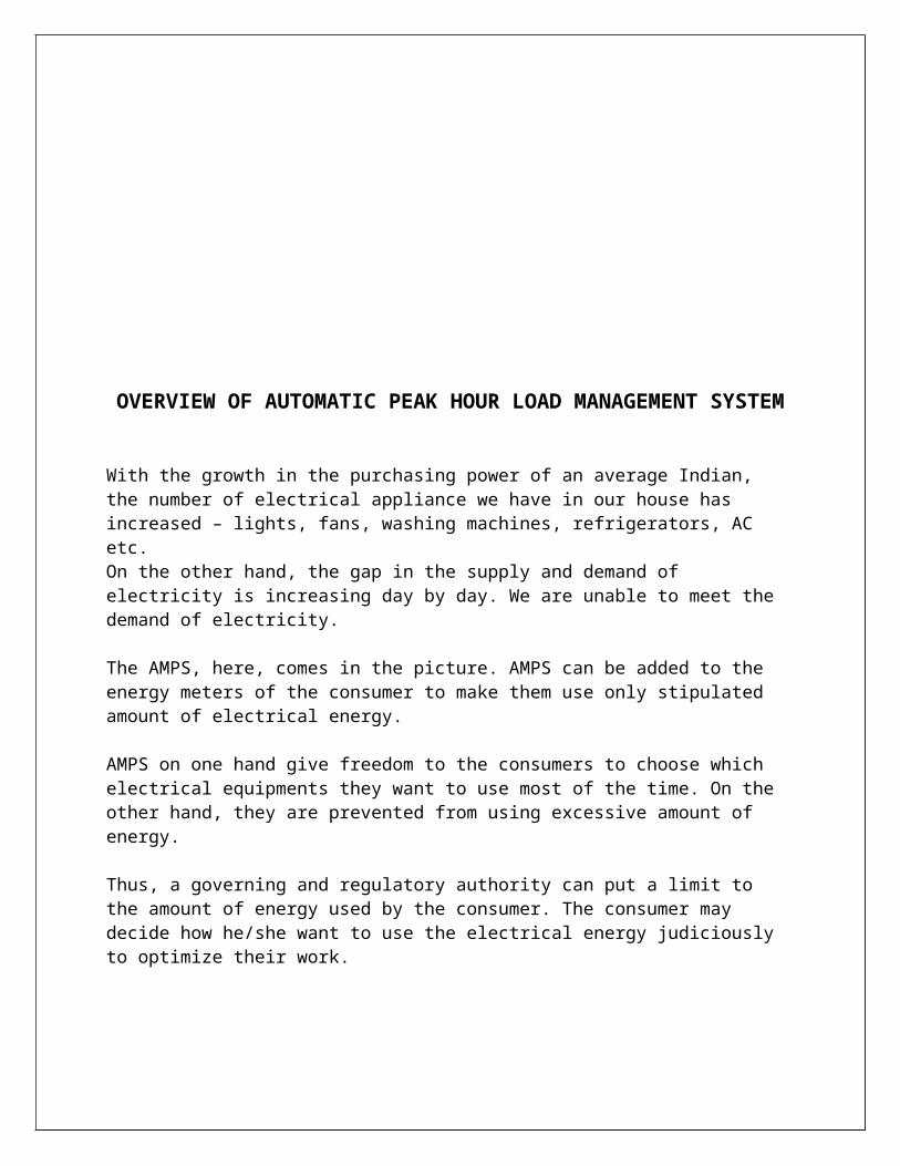
OVERVIEW OF AUTOMATIC PEAK HOUR LOAD MANAGEMENT SYSTEM
With the growth in the purchasing power of an average Indian, the number of electrical appliance we have in our house has increased – lights, fans, washing machines, refrigerators, AC etc.On the other hand, the gap in the supply and demand of electricity is increasing day by day. We are unable to meet the demand of electricity.
The AMPS, here, comes in the picture. AMPS can be added to the energy meters of the consumer to make them use only stipulated amount of electrical energy.
AMPS on one hand give freedom to the consumers to choose which electrical equipments they want to use most of the time. On the other hand, they are prevented from using excessive amount of energy.
Thus, a governing and regulatory authority can put a limit to the amount of energy used by the consumer. The consumer may decide how he/she want to use the electrical energy judiciously to optimize their work.
WORKING OF ADVANCED POWER LOAD MANAGEMENT SYSTEM
The operating voltage of the main circuit is 230 Volts. The PIC microcontroller works at 5 Volts. The main voltage is reduced to 12 volts using transformer. And it is then rectified at 12 Volts using bridge rectifier. The voltage is reduced to 5 Volts using voltage transformer. As the voltage of the main supply does not remain constant at 230 Volts but keeps on fluctuating, therefore, it is not directly reduced to 5 Volts using transformer.
The energy meter has a Light Dependent Resistor together with an LED. The combination of LED and LDR is connected to the transistor and microcontroller. There are three types of connections through the energy meter according to the priority of the consumers:-
HIGH PRIORITY EQUIPMENTS:-
These are those equipments which are to be used by a consumer all the time like lights, security systems.
MEDIUM PRIORITY EQUIPMENTS:-
These are those equipments which are to be used intermittently and consume more power like washing machine, fans
LOW PRIORITY EQUIPMENTS:-
These are those equipments which are according to consumers has got the least priority.
According to energy usage, the LED will blink. For every kWh of energy used the LED will blink 1200 times. If the amount of electrical power used is greater, the LED will blink more number of times. Otherwise smaller number of times.
As the LED is connected to LDR, the resistance of LDR will change with the change in the state of the LED. The changing resistance of LDR will turn- on or turn-off the transistor by varying the current flowing through its terminals.
As the energy consumed by the consumer passes the ceiling, the energy meter will automatically disconnect the lowest priority equipments. The medium priority and high priority equipments are left untouched.Again if the energy usage is more medium priority equipments will get disconnected from supply system.
If even with the high priority equipments, the energy usage is more then even this connection will get disconnected from the supply system.
The relay will be used by the PIC microcontroller to disconnect the equipment from the supply system.

PRINTED CIRCUIT BOARD (PCB) CONSTRUCTION
A printed circuit board, or PCB, is used to mechanically support and electrically connect electronic components using conductive pathways, track or signal traces etched from copper sheets laminated onto a non-conductive substrate. It is also referred to as printed wiring board (PWB) or etched wiring board. A PCB populated with electronic components is a printed circuit assembly (PCA), also known as printed circuit board assembly (PCBA). Printed circuit boards are used virtually all but the simplest commercially produced electronic devices.PCBs are inexpensive, and can be highly reliable. They require much more layout effort and higher initial cost than either wire wrap or point- to- point construction, but are much cheaper and faster for high-volume production; the production and soldering of PCBs can be done by totally automated equipment. Much of the electronics industry’s PCB design, assembly, and quality control needs are set by standards that are published by the IPC organization.
PCB LAYOUT

PROGRAMME FOR MICROCONTROLLER
Pin Map:
RB0 : Digital wattmeter interfaceRC0 : Relay1RC1 : Relay2RC2 : Relay3RC7 : RxRC6 : Tx
====================================================*/
#include<pic.h>#include<stdio.h>#include<string.h>#include"delay.h"#include"ioports.h"#include"sci.h"
#define Low_priority_On RC0=1//RC0=1#define Low_priority_Off RC0=0//RC0=0#define Medium_priority_On RC2=1//RC2=1#define Medium_priority_Off RC2=0//RC2=0#define High_priority_On RC1=1//RC1=1#define High_priority_Off RC1=0//RC1=0
unsigned int tmr1flag=0,alloc=18,usage=0;//alloc=18unsigned char ALLOC_AR[15],P_AR[15]={0},sflag=0,sec=0;bit flag=0;
void main(){
config_ioports();sci_Init(9600,SCI_EIGHT);INTE=1;INTF=0;PEIE=1;TMR1IE=1;TMR1IF=0;T1CKPS1 =1;T1CKPS0 =1;GIE=1;TMR1H=0;TMR1L=0;

Low_priority_On;Medium_priority_On;High_priority_On;
sci_Puts("APMS\n\r");DelayMs(50);sci_Puts("Initialising........\n\r");DelayMs(200);sci_Puts("Communication_established\n\r");DelayMs(100);
while(1){
TMR1ON=1;if(sflag==1){
INTE=0;sflag=0;TMR1ON=0;sprintf(P_AR,"USG:%d\n\r",usage);sci_Puts(P_AR);if(usage<=alloc){
Low_priority_On;DelayMs(50);Medium_priority_On;DelayMs(50);High_priority_On;DelayMs(50);sci_Puts("All_On\n\r");
//Debug_Code}if(usage>alloc){
Low_priority_Off;DelayMs(80);Medium_priority_On;High_priority_On;sci_Puts("Low_priority_Off\n\r");
//Debug_Code}
if(usage>(alloc+6))//(alloc+7{
Low_priority_Off;DelayMs(80);

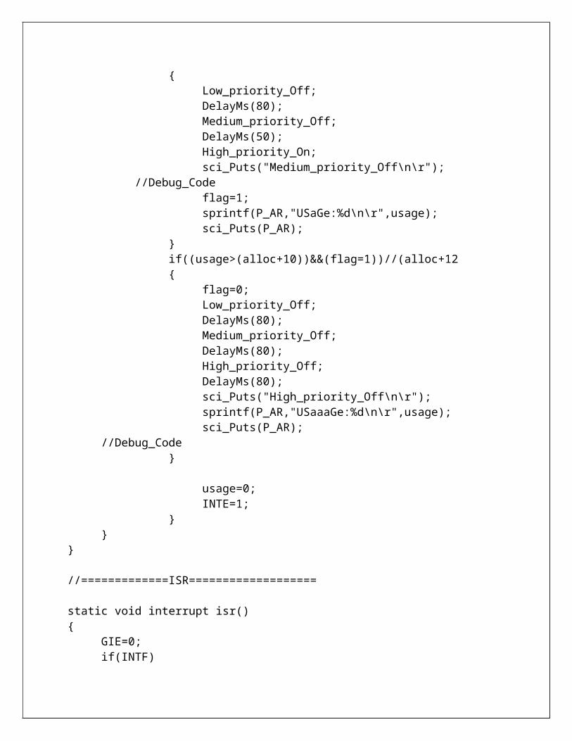
Medium_priority_Off;DelayMs(50);High_priority_On;sci_Puts("Medium_priority_Off\n\r");
//Debug_Codeflag=1;sprintf(P_AR,"USaGe:%d\n\r",usage);sci_Puts(P_AR);
}if((usage>(alloc+10))&&(flag=1))//(alloc+12{
flag=0;Low_priority_Off;DelayMs(80);Medium_priority_Off;DelayMs(80);High_priority_Off;DelayMs(80);sci_Puts("High_priority_Off\n\r");sprintf(P_AR,"USaaaGe:%d\n\r",usage);sci_Puts(P_AR); //Debug_Code
}
usage=0;INTE=1;
}}
}
//=============ISR===================
static void interrupt isr(){
GIE=0;if(INTF){
INTF=0;usage++;
}if(TMR1IF){
TMR1IF=0;tmr1flag++;
}if(tmr1flag>1){

sec++;tmr1flag=0;
}if(sec==40)//40{
usage=usage+10;sflag=1;sec=0;
}GIE=1;
}

CIRCUIT DIAGRAM

COMPONENTS LIST
SL.NO. COMPONENT QUANTITY PRICE
1 PIC 16F883 1 1702 7805 1 123 WATTHOUR METER 1 7504 T/F 0-12/500Ma 1 755 AC CODE WIRE 1 156 BULB HOLDER 3 757 BRIDGE RECTIFIER W04 1 48 MICROSWITCH 1 39 RESISTORS 10 25010 PN JUNCTION DIODE IN4007 4 211 CAPACITOR 1000uF/25V 1 812 CAPACITOR 10Uf/16V 1 313 IC BED 28 PIN 1 214 PCB 1 25015 ACRYLIC SHEET 1SQ, FEET 8016 LDR 1 3

LOAD MANAGEMENT
Load management, also known as demand side management (DSM), is the process
of balancing the supply of electricity on the network with the electrical load by adjusting or
controlling the load rather than the power station output. This can be achieved by direct
intervention of the utility in real time, by the use of frequency sensitive relays triggering circuit
breakers (ripple control), by time clocks, or by using special tariffs to influence consumer
behavior. Load management allows utilities to reduce demand for electricity during peak usage
times, which can, in turn, reduce costs by eliminating the need for peaking power plants. In
addition, peaking power plants also often require hours to bring on-line, presenting challenges
should a plant go off-line unexpectedly. Load management can also help reduce harmful
emission, since peaking plants or backup generators are often dirtier and less efficient than base
load power plants. New load-management technologies are constantly under development —
both by private industry and public entities.
ADVANTAGES AND OPERATING PRINCIPLES
Since electrical energy is a form of energy that cannot be effectively stored in bulk, it must be generated, distributed, and consumed immediately. When the load on a system approaches the maximum generating capacity, network operators must either find additional supplies of energy or find ways to curtail the load, hence load management. If they are unsuccessful, the system will become unstable and blackouts can occur.
Long-term load management planning may begin by building sophisticated models to describe the physical properties of the distribution network (i.e. topology, capacity, and other characteristics of the lines), as well as the load behavior. The analysis may include scenarios that account for weather forecasts, the predicted impact of proposed load-shed commands, estimated time-to-repair for off-line equipment, and other factors.
The utilization of load management can help a power plant achieve a higher capacity factor, a measure of average capacity utilization. Capacity factor is a measure of the output of a power plant compared to the maximum output it could produce. Capacity factor is often defined as the ratio of average load to capacity or the ratio of average load to peak load in a period of time. A higher load factor is advantageous because a power plant may be less efficient at low load factors, a high load factor means fixed costs are spread over more kWh of output (resulting in a lower price per unit of electricity), and a higher load factor means greater total output. If the power load factor is affected by non-availability of fuel, maintenance shut-down, unplanned breakdown, or reduced demand (as consumption pattern fluctuate throughout the day), the generation has to be adjusted, since grid energy storage is often prohibitively expensive.

Smaller utilities that buy power instead of generating their own find that they can also benefit by installing a load control system. The penalties they must pay to the energy provider for peak usage can be significantly reduced. Many report that a load control system can pay for itself in a single season.
COMPARISONS TO DEMAND RESPONSE
When the decision is made to curtail load, it is done so on the basis of system reliability. The utility in a sense "owns the switch" and sheds loads only when the stability or reliability of the electrical distribution system is threatened. The utility (being in the business of generating, transporting, and delivering electricity) will not disrupt their business process without due cause. Load management, when done properly, is non-invasive, and imposes no hardship on the consumer.
Demand response places the "on-off switch" in the hands of the consumer using devices such as a smart grid controlled load control switch. While many residential consumers pay a flat rate for electricity year-round, the utility's costs actually vary constantly, depending on demand, the distribution network, and composition of the company's electricity generation portfolio. In a free market, the wholesale price of energy varies widely throughout the day. Demand response programs such as those enabled by smart grids attempt to incentivize the consumer to limit usage based upon cost concerns. As costs rise during the day (as the system reaches peak capacity and more expensive peaking power plants are used), a free market economy should allow the price to rise. A corresponding drop in demand for the commodity should meet a fall in price. While this works for predictable shortages, many crises develop within seconds due to unforeseen equipment failures. They must be resolved in the same time-frame in order to avoid a power blackout. Many utilities who are interested in demand response have also expressed an interest in load control capability so that they might be able to operate the "on-off switch" before price updates could be published to the consumers.
The application of load control technology continues to grow today with the sale of both radio frequency and power line communication based systems. Certain types of smart meter systems can also serve as load control systems.
The largest residential load control system in the world is found in Florida and is managed by Florida Power and Light. It utilizes 800,000 Load Control Transponders (LCTs) and controls 1,000 MW of electrical power (2,000 MW in an emergency). FPL has been able to avoid the construction of numerous new power plants due to their load management programs.

RIPPLE FACTOR
Ripple control is the most common form of load control, and is used in many countries around the world, including Australia, New Zealand, the United Kingdom, Germany, and South Africa. Ripple control involves superimposing a higher-frequency signal (usually between 100 and 1600 Hz onto the standard 50–60 Hz of the main power signal. When receiver devices attached to non-essential residential or industrial loads receive this signal, they shut down the load until the signal is disabled or another frequency signal is received.
Early implementations of ripple control occurred during World War II in various parts of the world using a system that communicates over the electrical distribution system. Ripple control systems are generally paired with a two- (or more) tiered pricing system, whereby electricity is more expensive during peak times (evenings) and cheaper during low-usage times (early morning).
Affected residential devices will vary by region, but may include residential electric hot-water heaters, air conditioners, pool pumps, or crop-irrigation pumps. In a distribution network outfitted with load control, these devices are outfitted with communicating controllers that can run a program that limits the duty cycle of the equipment under control. Consumers are usually rewarded for participating in the load control program by paying a reduced rate for energy. Proper load management by the utility allows them to practice load shedding to avoid rolling blackouts and reduce costs.

SMART GRID
A smart grid is an electrical grid that uses information and communications technology to gather and act on information, such as information about the behaviors of suppliers and consumers, in an automated fashion to improve the efficiency, reliability, economics, and sustainability of the production and distribution of electricity.
Smart grid policy is organized in Europe as Smart Grid European Technology Platform. Policy in the United States is described in 42 U.S.C. ch.152 subch.IX § 17381.
Roll-out of smart grid technology also implies a fundamental re-engineering of the electricity services industry, although typical usage of the term is focused on the technical infrastructure.
Modernization opportunities
Since the early 21st century, opportunities to take advantage of improvements in electronic communication technology to resolve the limitations and costs of the electrical grid have become apparent. Technological limitations on metering no longer force peak power prices to be averaged out and passed on to all consumers equally. In parallel, growing concerns over environmental damage from fossil-fired power stations has led to a desire to use large amounts of renewable energy. Dominant forms such as wind power and solar power are highly variable, and so the need for more sophisticated control systems became apparent, to facilitate the connection of sources to the otherwise highly controllable grid. Power from photovoltaic cells (and to a lesser extent wind turbines) has also, significantly, called into question the imperative for large, centralized power stations. The rapidly falling costs point to a major change from the centralized grid topology to one that is highly distributed, with power being both generated and consumed right at the limits of the grid. Finally, growing concern over terrorist attack in some countries has led to calls for a more robust energy grid that is less dependent on centralized power stations that were perceived to be potential attack targets.
Origin of the term "smart grid"
The term smart grid has been in use since at least 2005, when it appeared in the article "Toward A Smart Grid" by Amin and Wollenberg. The term had been used previously and may date as far back as 1998. There are many smart grid definitions, some functional, some technological, and some benefits-oriented. A common element to most definitions is the application of digital processing and communications to the power grid, making data flow and information management central to the smart grid. Various capabilities result from the deeply integrated use of digital technology with power grids, and integration of the new grid information flows into utility processes and systems is one of the key issues in the design of smart grids. Electric utilities now find themselves making three classes of transformations: improvement of infrastructure, called the strong grid in China; addition of the digital layer, which is the essence of the smart grid; and business process transformation, necessary to capitalize on the

investments in smart technology. Much of the modernization work that has been going on in electric grid modernization, especially substation and distribution automation, is now included in the general concept of the smart grid, but additional capabilities are evolving as well.
Features of SMART GRID
The smart grid represents the full suite of current and proposed responses to the challenges of electricity supply. Because of the diverse range of factors there are numerous competing taxonomies and no agreement on a universal definition. Nevertheless, one possible categorisation is given here.
Reliability
The smart grid will make use of technologies that improve fault detection and allow self-healing of the network without the intervention of technicians. This will ensure more reliable supply of electricity, and reduced vulnerability to natural disasters or attack.
Although multiple routes are touted as a feature of the smart grid, the old grid also featured multiple routes. Initial power lines in the grid were built using a radial model, later connectivity was guaranteed via multiple routes, referred to as a network structure. However, this created a new problem: if the current flow or related effects across the network exceed the limits of any particular network element, it could fail, and the current would be shunted to other network elements, which eventually may fail also, causing a domino effect. A technique to prevent this is load shedding by rolling blackout or voltage reduction (brownout).
Flexibility in network topology
Next-generation transmission and distribution infrastructure will be better able to handle possible bidirectional energy flows, allowing for distributed generation such as from photovoltaic panels on building roofs, but also the use of fuel cells, charging to/from the batteries of electric cars, wind turbines, pumped hydroelectric power, and other sources.
Classic grids were designed for one-way flow of electricity, but if a local sub-network generates more power than it is consuming, the reverse flow can raise safety and reliability issues. A smart grid aims to manage these situations.
Efficiency
Numerous contributions to overall improvement of the efficiency of energy infrastructure is anticipated from the deployment of smart grid technology, in particular including demand-side management, for example turning off air conditioners during short-term spikes in electricity price. The overall effect is less redundancy in transmission and distribution lines, and greater utilisation of generators, leading to lower power prices.
Load adjustment
The total load connected to the power grid can vary significantly over time. Although the total load is the sum of many individual choices of the clients, the overall load is not a stable, slow varying, average power consumption. Imagine the increment of the load if a popular television program starts and millions of televisions will draw current instantly. Traditionally, to respond to

a rapid increase in power consumption, faster than the start-up time of a large generator, some spare generators are put on a dissipative standby mode. A smart grid may warn all individual television sets, or another larger customer, to reduce the load temporarily (to allow time to start up a larger generator) or continuously (in the case of limited resources). Using mathematical prediction algorithms it is possible to predict how many standby generators need to be used, to reach a certain failure rate. In the traditional grid, the failure rate can only be reduced at the cost of more standby generators. In a smart grid, the load reduction by even a small portion of the clients may eliminate the problem.
Peak curtailment/leveling and time of use pricing
To reduce demand during the high cost peak usage periods, communications and metering technologies inform smart devices in the home and business when energy demand is high and track how much electricity is used and when it is used. It also gives utility companies the ability to reduce consumption by communicating to devices directly in order to prevent system overloads. Examples would be a utility reducing the usage of a group of electric vehicle charging stations or shifting temperature set points of air conditioners in a city. To motivate them to cut back use and perform what is called peak curtailment or peak leveling, prices of electricity are increased during high demand periods, and decreased during low demand periods. It is thought that consumers and businesses will tend to consume less during high demand periods if it is possible for consumers and consumer devices to be aware of the high price premium for using electricity at peak periods. This could mean making trade-offs such as cycling on/off air conditioners or running dishes at 9 pm instead of 5 pm. When businesses and consumers see a direct economic benefit of using energy at off-peak times become more energy efficient, the theory is that they will include energy cost of operation into their consumer device and building construction decisions.
According to proponents of smart grid plans, this will reduce the amount of spinning reserve that electric utilities have to keep on stand-by, as the load curve will level itself through a combination of "invisible hand" free-market capitalism and central control of a large number of devices by power management services that pay consumers a portion of the peak power saved by turning their devices off.
Sustainability
The improved flexibility of the smart grid permits greater penetration of highly variable renewable energy sources such as solar power and wind power, even without the addition of energy storage. Current network infrastructure is not built to allow for many distributed feed-in points, and typically even if some feed-in is allowed at the local (distribution) level, the transmission-level infrastructure cannot accommodate it. Rapid fluctuations in distributed generation, such as due to cloudy or gusty weather, present significant challenges to power engineers who need to ensure stable power levels through varying the output of the more controllable generators such as gas turbines and hydroelectric generators. Smart grid technology is a necessary condition for very large amounts of renewable electricity on the grid for this reason.

Market-enabling
The smart grid allows for systematic communication between suppliers (their energy price) and consumers (their willingness-to-pay), and permits both the suppliers and the consumers to be more flexible and sophisticated in their operational strategies. Only the critical loads will need to pay the peak energy prices, and consumers will be able to be more strategic in when they use energy. Generators with greater flexibility will be able to sell energy strategically for maximum profit, whereas inflexible generators such as base-load steam turbines and wind turbines will receive a varying tariff based on the level of demand and the status of the other generators currently operating. The overall effect is a signal that awards energy efficiency, and energy consumption that is sensitive to the time-varying limitations of the supply. At the domestic level, appliances with a degree of energy storage or thermal mass (such as refrigerators, heat banks, and heat pumps) will be well placed to 'play' the market and seek to minimise energy cost by adapting demand to the lower-cost energy support periods. This is an extension of the dual-tariff energy pricing mentioned above.
Demand response support
Demand response support allows generators and loads to interact in an automated fashion in real time, coordinating demand to flatten spikes. Eliminating the fraction of demand that occurs in these spikes eliminates the cost of adding reserve generators, cuts wear and tear and extends the life of equipment, and allows users to cut their energy bills by telling low priority devices to use energy only when it is cheapest.
Currently, power grid systems have varying degrees of communication within control systems for their high value assets, such as in generating plants, transmission lines, substations and major energy users. In general information flows one way, from the users and the loads they control back to the utilities. The utilities attempt to meet the demand and succeed or fail to varying degrees (brownout, rolling blackout, uncontrolled blackout). The total amount of power demand by the users can have a very wide probability distribution which requires spare generating plants in standby mode to respond to the rapidly changing power usage. This one-way flow of information is expensive; the last 10% of generating capacity may be required as little as 1% of the time, and brownouts and outages can be costly to consumers.
Latency of the data flow is a major concern, with some early smart meter architectures allowing actually as long as 24 hours delay in receiving the data, preventing any possible reaction by either supplying or demanding devices.
Platform for advanced services
As with other industries, use of robust two-way communications, advanced sensors, and distributed computing technology will improve the efficiency, reliability and safety of power delivery and use. It also opens up the potential for entirely new services or improvements on existing ones, such as fire monitoring and alarms that can shut off power, make phone calls to emergency services, etc.

Provision megabits, control power with kilobits, sell the rest
The amount of data required to perform monitoring and switching your appliances off automatically is very small compared with that already reaching even remote homes to support voice, security, Internet and TV services. Many smart grid bandwidth upgrades are paid for by over-provisioning to also support consumer services, and subsidizing the communications with energy-related services or subsidizing the energy-related services, such as higher rates during peak hours, with communications. This is particularly true where governments run both sets of services as a public monopoly. Because power and communications companies are generally separate commercial enterprises in North America and Europe, it has required considerable government and large-vendor effort to encourage various enterprises to cooperate. Some, like Cisco, see opportunity in providing devices to consumers very similar to those they have long been providing to industry. Others, such as Silver Spring Networks or Google, are data integrators rather than vendors of equipment. While the AC power control standards suggest powerline networking would be the primary means of communication among smart grid and home devices, the bits may not reach the home via Broadband over Power Lines (BPL) initially but by fixed wireless.
Technology
The bulk of smart grid technologies are already used in other applications such as manufacturing and telecommunications and are being adapted for use in grid operations. In general, smart grid technology can be grouped into five key areas:
Integrated communications
Some communications are up to date, but are not uniform because they have been developed in an incremental fashion and not fully integrated. In most cases, data is being collected via modem rather than direct network connection. Areas for improvement include: substation automation, demand response, distribution automation, supervisory control and data acquisition (SCADA), energy management systems, wireless mesh networks and other technologies, power-line carrier communications, and fiber-optics. Integrated communications will allow for real-time control, information and data exchange to optimize system reliability, asset utilization, and security.
Sensing and measurement
Core duties are evaluating congestion and grid stability, monitoring equipment health, energy theft prevention, and control strategies support. Technologies include: advanced microprocessor meters (smart meter) and meter reading equipment, wide-area monitoring systems, dynamic line rating (typically based on online readings by Distributed temperature sensing combined with Real time thermal rating (RTTR) systems), electromagnetic signature measurement/analysis, time-of-use and real-time pricing tools, advanced switches and cables, backscatter radio technology, and Digital protective relays.

Smart meters
A smart grid replaces analog mechanical meters with digital meters that record usage in real time. Smart meters are similar to Advanced Metering Infrastructure meters and provide a communication path extending from generation plants to electrical outlets (smart socket) and other smart grid-enabled devices. By customer option, such devices can shut down during times of peak demand.
Phasor measurement units
High speed sensors called PMUs distributed throughout their network can be used to monitor power quality and in some cases respond automatically to them. Phasors are representations of the waveforms of alternating current, which ideally in real-time, are identical everywhere on the network and conform to the most desirable shape. In the 1980s, it was realized that the clock pulses from global positioning system (GPS) satellites could be used for very precise time measurements in the grid. With large numbers of PMUs and the ability to compare shapes from alternating current readings everywhere on the grid, research suggests that automated systems will be able to revolutionize the management of power systems by responding to system conditions in a rapid, dynamic fashion.
A wide-area measurement system (WAMS) is a network of PMUS that can provide real-time monitoring on a regional and national scale. Many in the power systems engineering community believe that the Northeast blackout of 2003 would have been contained to a much smaller area if a wide area phasor measurement network was in place.
OPPOSITION AND CONCERNS
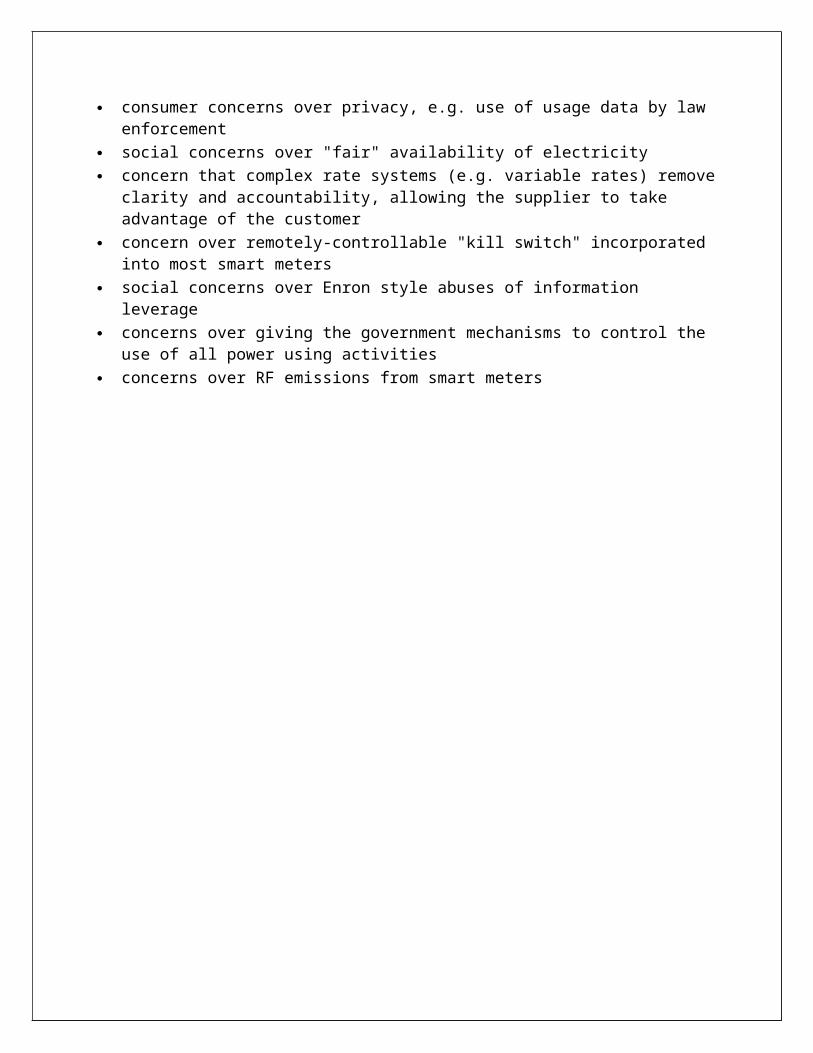
Most opposition and concerns have centered on smart meters and the items such remote control, remote disconnect, and variable rate pricing) enabled by them. Where opposition to smart meters is encountered, they are often marketed as "smart grid" which connects smart grid to smart meters in the eyes of opponents. Specific points of opposition or concern include:
consumer concerns over privacy, e.g. use of usage data by law enforcement social concerns over "fair" availability of electricity concern that complex rate systems (e.g. variable rates) remove clarity and accountability,
allowing the supplier to take advantage of the customer concern over remotely-controllable "kill switch" incorporated into most smart meters

social concerns over Enron style abuses of information leverage concerns over giving the government mechanisms to control the use of all power using
activities concerns over RF emissions from smart meters

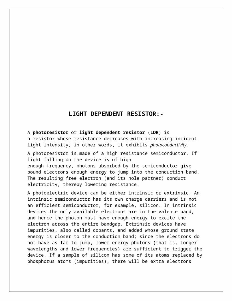
LIGHT DEPENDENT RESISTOR:-
A photoresistor or light dependent resistor (LDR) is a resistor whose resistance decreases with increasing incident light intensity; in other words, it exhibits photoconductivity.
A photoresistor is made of a high resistance semiconductor. If light falling on the device is of high enough frequency, photons absorbed by the semiconductor give bound electrons enough energy to jump into the conduction band. The resulting free electron (and its hole partner) conduct electricity, thereby lowering resistance.
A photoelectric device can be either intrinsic or extrinsic. An intrinsic semiconductor has its own charge carriers and is not an efficient semiconductor, for example, silicon. In intrinsic devices the only available electrons are in the valence band, and hence the photon must have enough energy to excite the electron across the entire bandgap. Extrinsic devices have impurities, also called dopants, and added whose ground state energy is closer to the conduction band; since the electrons do not have as far to jump, lower energy photons (that is, longer wavelengths and lower frequencies) are sufficient to trigger the device. If a sample of silicon has some of its atoms replaced by phosphorus atoms (impurities), there will be extra electrons available for conduction. This is an example of an extrinsic semiconductor. Photoresistors are basically photocells.
APPLICATIONS
Photoresistors come in many types. Inexpensive cadmium sulphide cells can be found in many consumer items such as camera light meters, street lights, clock radios, alarm devices, outdoor clocks, solar street lamps and solar road studs, etc.
They are also used in some dynamic compressors together with a small incandescent lamp or light emitting diode to control gain reduction and are also used in bed lamps, etc.
Lead sulphide (PbS) and indium antimonide (InSb) LDRs (light dependent resistor) are used for the mid infrared spectral region. Ge:Cu photoconductors are among the best far-infrared detectors available, and are used for infrared astronomy and infrared spectroscopy.

BRIDGE RECTIFIER
It uses four diodes connected across the main supply.OPERATIONWhen the input voltage is positive , the diodes D1 and D2 are forward biased and conduct some current .A voltage is developed across the resistance RL due to the current flow through it. The voltage looks like the positive half of the input cycle. At this time the diodes D3 and D4 are reverse biased. When the input voltage is negative, the diodes D3 and D4 are forward biased and conduct some current in the same direction through RL as during the positive half cycle. During this time, the diodes D1 and D2 are reverse biased. As a result of this action, a full-wave rectified output voltage is developed across the resistance RL.

RELAY
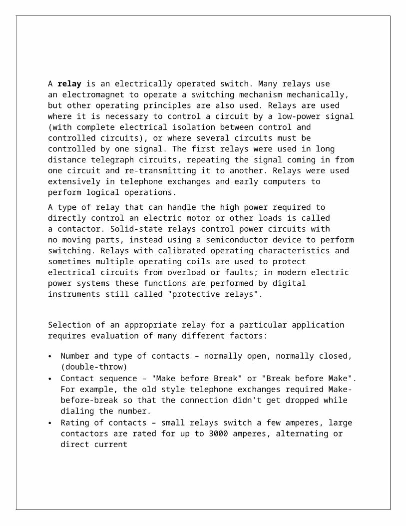
A relay is an electrically operated switch. Many relays use an electromagnet to operate a switching mechanism mechanically, but other operating principles are also used. Relays are used where it is necessary to control a circuit by a low-power signal (with complete electrical isolation between control and controlled circuits), or where several circuits must be controlled by one signal. The first relays were used in long distance telegraph circuits, repeating the signal coming in from one circuit and re-transmitting it to another. Relays were used extensively in telephone exchanges and early computers to perform logical operations.
A type of relay that can handle the high power required to directly control an electric motor or other loads is called a contactor. Solid-state relays control power circuits with no moving parts, instead using a semiconductor device to perform switching. Relays with calibrated operating characteristics and sometimes multiple operating coils are used to protect electrical circuits from overload or faults; in modern electric power systems these functions are performed by digital instruments still called "protective relays".
Selection of an appropriate relay for a particular application requires evaluation of many different factors:
Number and type of contacts – normally open, normally closed, (double-throw) Contact sequence – "Make before Break" or "Break before Make". For example, the old style
telephone exchanges required Make-before-break so that the connection didn't get dropped while dialing the number.
Rating of contacts – small relays switch a few amperes, large contactors are rated for up to 3000 amperes, alternating or direct current
Voltage rating of contacts – typical control relays rated 300 VAC or 600 VAC, automotive types to 50 VDC, special high-voltage relays to about 15 000 V
Operating lifetime, useful life - the number of times the relay can be expected to operate reliably. There is both a mechanical life and a contact life; the contact life is naturally affected by the kind of load being switched.
Coil voltage – machine-tool relays usually 24 VDC, 120 or 250 VAC, relays for switchgear may have 125 V or 250 VDC coils, "sensitive" relays operate on a few milli amperes
Coil current - including minimum current required to operate reliably and minimum current to hold. Also effects of power dissipation on coil temperature at various duty cycles.
Package/enclosure – open, touch-safe, double-voltage for isolation between circuits, explosion proof, outdoor, oil and splash resistant, washable for printed circuit board assembly
Operating environment - minimum and maximum operating temperatures and other environmental considerations such as effects of humidity and salt

Assembly – Some relays feature a sticker that keeps the enclosure sealed to allow PCB post soldering cleaning, which is removed once assembly is complete.
Mounting – sockets, plug board, rail mount, panel mount, through-panel mount, enclosure for mounting on walls or equipment
Switching time – where high speed is required "Dry" contacts – when switching very low level signals, special contact materials may be
needed such as gold-plated contacts Contact protection – suppress arcing in very inductive circuits Coil protection – suppress the surge voltage produced when switching the coil current Isolation between coil contacts Aerospace or radiation-resistant testing, special quality assurance Expected mechanical loads due to acceleration – some relays used in aerospace applications
are designed to function in shock loads of 50 g or more Accessories such as timers, auxiliary contacts, pilot lamps, test buttons Regulatory approvals Stray magnetic linkage between coils of adjacent relays on a printed circuit board.
There are many considerations involved in the correct selection of a control relay for a particular application. These considerations include factors such as speed of operation, sensitivity, and hysteresis. Although typical control relays operate in the 5 ms to 20 ms range, relays with switching speeds as fast as 100 us are available. Reed relays which are actuated by low currents and switch fast are suitable for controlling small currents.
As for any switch, the current through the relay contacts (unrelated to the current through the coil) must not exceed a certain value to avoid damage. In the particular case of high-inductance circuits such as motors other issues must be addressed. When a power source is connected to an inductance, an input surge current which may be several times larger than the steady current exists. When the circuit is broken, the current cannot change instantaneously, which creates a potentially damaging spark across the separating contacts.
Consequently for relays which may be used to control inductive loads we must specify the maximum current that may flow through the relay contacts when it actuates, the make rating; the continuous rating; and the break rating. The make rating may be several times larger than the continuous rating, which is itself larger than the break rating.

PERIPHERAL INTERFACE CONTROLLER (PIC)
PIC is a family of modified Harvard Architecture microcontrollers made by Microchip Technology, derived from the PIC1650 originally developed by General Instrument's Microelectronics Division. The name PIC initially referred to "Peripheral Interface Controller".
PICs are popular due to their low cost, wide availability, large user base, extensive collection of application notes, availability of low cost or free development tools, and serial programming (and re-programming with flash memory) capability. They are also commonly used in educational programming as they often come with the easy to use 'pic logicator' software.
CORE ARCHITECTURE:-
The PIC architecture is characterized by its multiple attributes:
Separate code and data spaces (Harvard architecture). A small number of fixed length instructions Most instructions are single cycle execution (2 clock cycles, or 4 clock cycles in 8-bit
models), with one delay cycle on branches and skips One accumulator (W0), the use of which (as source operand) is implied (i.e. is not encoded
in the opcode) All RAM locations function as registers as both source and/or destination of math and other
functions. A hardware stack for storing return addresses A small amount of addressable data space (32, 128, or 256 bytes, depending on the family),
extended through banking Data space mapped CPU, port, and peripheral registers ALU status flags are mapped into the data space

The program counter is also mapped into the data space and writable (this is used to implement indirect jumps).
There is no distinction between memory space and register space because the RAM serves the job of both memory and registers, and the RAM is usually just referred to as the register file or simply as the registers.
Data space (RAM)
PICs have a set of registers that function as general purpose RAM. Special purpose control
registers for on-chip hardware resources are also mapped into the data space. The addressability
of memory varies depending on device series, and all PIC devices have some banking
mechanism to extend addressing to additional memory. Later series of devices feature move
instructions which can cover the whole addressable space, independent of the selected bank. In
earlier devices, any register move had to be achieved via the accumulator.
To implement indirect addressing, a "file select register" (FSR) and "indirect register" (INDF)
are used. A register number is written to the FSR, after which reads from or writes to INDF will
actually be to or from the register pointed to by FSR. Later devices extended this concept with
post- and pre- increment/decrement for greater efficiency in accessing sequentially stored data.
This also allows FSR to be treated almost like a stack pointer (SP).
External data memory is not directly addressable except in some high pin count PIC18 devices.
Code space
The code space is generally implemented as ROM, EPROM or flash ROM. In general, external
code memory is not directly addressable due to the lack of an external memory interface. The
exceptions are PIC17 and select high pin count PIC18 devices.
Word size
All PICs handle (and address) data in 8-bit chunks. However, the unit of addressability of the
code space is not generally the same as the data space. For example, PICs in the baseline (PIC12)
and mid-range (PIC16) families have program memory addressable in the same wordsize as the
instruction width, i.e. 12 or 14 bits respectively. In contrast, in the PIC18 series, the program
memory is addressed in 8-bit increments (bytes), which differs from the instruction width of 16
bits.
In order to be clear, the program memory capacity is usually stated in number of (single word)
instructions, rather than in bytes.

Stacks
PICs have a hardware call stack, which is used to save return addresses. The hardware stack is
not software accessible on earlier devices, but this changed with the 18 series devices.
Hardware support for a general purpose parameter stack was lacking in early series, but this
greatly improved in the 18 series, making the 18 series architecture more friendly to high level
language compilers.
Instruction set
A PIC's instructions vary from about 35 instructions for the low-end PICs to over 80 instructions
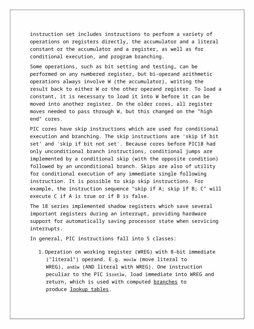
for the high-end PICs. The instruction set includes instructions to perform a variety of operations
on registers directly, the accumulator and a literal constant or the accumulator and a register, as
well as for conditional execution, and program branching.
Some operations, such as bit setting and testing, can be performed on any numbered register, but
bi-operand arithmetic operations always involve W (the accumulator), writing the result back to
either W or the other operand register. To load a constant, it is necessary to load it into W before
it can be moved into another register. On the older cores, all register moves needed to pass
through W, but this changed on the "high end" cores.
PIC cores have skip instructions which are used for conditional execution and branching. The
skip instructions are 'skip if bit set' and 'skip if bit not set'. Because cores before PIC18 had only
unconditional branch instructions, conditional jumps are implemented by a conditional skip
(with the opposite condition) followed by an unconditional branch. Skips are also of utility for
conditional execution of any immediate single following instruction. It is possible to skip skip
instructions. For example, the instruction sequence "skip if A; skip if B; C" will execute C if A is
true or if B is false.
The 18 series implemented shadow registers which save several important registers during an
interrupt, providing hardware support for automatically saving processor state when servicing
interrupts.
In general, PIC instructions fall into 5 classes:
1. Operation on working register (WREG) with 8-bit immediate ("literal") operand.
E.g. movlw (move literal to WREG), andlw (AND literal with WREG). One instruction
peculiar to the PIC isretlw, load immediate into WREG and return, which is used with
computed branches to produce lookup tables.
2. Operation with WREG and indexed register. The result can be written to either the
Working register (e.g. addwf reg,w). or the selected register (e.g. addwf reg,f).
3. Bit operations. These take a register number and a bit number, and perform one of 4
actions: set or clear a bit, and test and skip on set/clear. The latter are used to perform
conditional branches. The usual ALU status flags are available in a numbered register so
operations such as "branch on carry clear" are possible.
4. Control transfers. Other than the skip instructions previously mentioned, there are only
two: goto and call.
5. A few miscellaneous zero-operand instructions, such as return from subroutine,
and sleep to enter low-power mode.Performance
The architectural decisions are directed at the maximization of speed-to-cost ratio. The PIC
architecture was among the first scalar CPU designs, and is still among the simplest and
cheapest. The Harvard architecture—in which instructions and data come from separate sources
—simplifies timing and microcircuit design greatly, and this benefits clock speed, price, and
power consumption.
The PIC instruction set is suited to implementation of fast lookup tables in the program space.
Such lookups take one instruction and two instruction cycles. Many functions can be modeled in
this way. Optimization is facilitated by the relatively large program space of the PIC (e.g. 4096 ×
14-bit words on the 16F690) and by the design of the instruction set, which allows for embedded
constants. For example, a branch instruction's target may be indexed by W, and execute a
"RETLW" which does as it is named - return with literal in W.
Interrupt latency is constant at three instruction cycles. External interrupts have to be
synchronized with the four clock instruction cycle, otherwise there can be a one instruction cycle
jitter. Internal interrupts are already synchronized. The constant interrupt latency allows PICs to
achieve interrupt driven low jitter timing sequences. An example of this is a video sync pulse
generator. This is no longer true in the newest PIC models, because they have a synchronous
interrupt latency of three or four cycles.
Advantages
The PIC architectures have these advantages:
Small instruction set to learn
RISC architecture
Built in oscillator with selectable speeds
Easy entry level, in circuit programming plus in circuit debugging PICKit units available for
less than $50
Inexpensive microcontrollers
Wide range of interfaces including I²C, SPI, USB, USART, A/D, programmable
comparators, PWM, LIN, CAN, PSP, and Ethernet
Availability of processors in DIL package make them easy to handle for hobby use.Limitations
The PIC architectures have these limitations:
One accumulator
Register-bank switching is required to access the entire RAM of many devices
Operations and registers are not orthogonal; some instructions can address RAM
and/or immediate constants, while others can only use the accumulator
The following stack limitations have been addressed in the PIC18 series, but still apply to earlier
cores:
The hardware call stack is not addressable, so preemptive task switching cannot be
implemented
Software-implemented stacks are not efficient, so it is difficult to generate reentrant code and
support local variables
With paged program memory, there are two page sizes to worry about: one for CALL and
GOTO and another for computed GOTO (typically used for table lookups). For example, on
PIC16, CALL and GOTO have 11 bits of addressing, so the page size is 2048 instruction words.
For computed GOTOs, where you add to PCL, the page size is 256 instruction words. In both
cases, the upper address bits are provided by the PCLATH register. This register must be
changed every time control transfers between pages. PCLATH must also be preserved by any
interrupt handler.


VOLATAGE REGULATOR
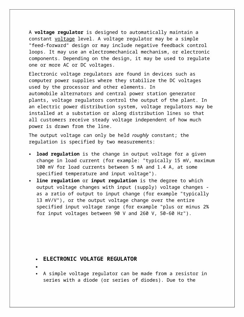
A voltage regulator is designed to automatically maintain a constant voltage level. A voltage regulator may be a simple "feed-forward" design or may include negative feedback control loops. It may use an electromechanical mechanism, or electronic components. Depending on the design, it may be used to regulate one or more AC or DC voltages.
Electronic voltage regulators are found in devices such as computer power supplies where they stabilize the DC voltages used by the processor and other elements. In automobile alternators and central power station generator plants, voltage regulators control the output of the plant. In an electric power distribution system, voltage regulators may be installed at a substation or along distribution lines so that all customers receive steady voltage independent of how much power is drawn from the line.
The output voltage can only be held roughly constant; the regulation is specified by two measurements:
load regulation is the change in output voltage for a given change in load current (for example: "typically 15 mV, maximum 100 mV for load currents between 5 mA and 1.4 A, at some specified temperature and input voltage").
line regulation or input regulation is the degree to which output voltage changes with input (supply) voltage changes - as a ratio of output to input change (for example "typically 13 mV/V"), or the output voltage change over the entire specified input voltage range (for example "plus or minus 2% for input voltages between 90 V and 260 V, 50-60 Hz").
ELECTRONIC VOLATGE REGULATOR A simple voltage regulator can be made from a resistor in series with a diode (or series of
diodes). Due to the logarithmic shape of diode V-I curves, the voltage across the diode changes only slightly due to changes in current drawn or changes in the input. When precise voltage control and efficiency are not important, this design may work fine.
Feedback voltage regulators operate by comparing the actual output voltage to some fixed reference voltage. Any difference is amplified and used to control the regulation element in such a way as to reduce the voltage error. This forms a negative feedback control loop; increasing the open-loop gain tends to increase regulation accuracy but reduce stability (avoidance of oscillation, or ringing during step changes). There will also be a trade-off between stability and the speed of the response to changes. If the output voltage is too low (perhaps due to input voltage reducing or load current increasing), the regulation element is commanded, up to a point, to produce a higher output voltage–by dropping less of the input voltage (for linear series regulators and buckswitching regulators), or to draw input current for longer periods (boost-type switching regulators); if the output voltage is too high, the regulation element will normally be commanded to produce a lower voltage. However, many regulators have over-current protection, so that they will entirely stop sourcing current (or limit the current in some way) if the output current is too high, and some regulators may also shut down if the input voltage is outside a given range .

RESISTORS
A resistor is a two-terminal electrical or electronic component that resists an electric current by
producing a voltage drop between its terminals in accordance with Ohm's law.
The electrical resistance is equal to the voltage drop across the resistor divided by the current
that is flowing through the resistor. Resistors are used as
part of electrical networks and electronic circuits.
Types
Fixed Resistors
Some resistors are cylindrical, with the actual resistive
material in the centre (composition resistors, now
obsolete) or on the surface of the cylinder (film) resistors,
and a conducting metal lead projecting along the axis of
the cylinder at each end(axial lead). There are carbon
film and metal film resistors. The photo above right shows a row of common resistors. Power
resistors come in larger packages designed to dissipate heat efficiently. At high power levels,
resistors tend to be wire wound types. Resistors used in computers and other devices are
typically much smaller, often in surface-mount packages without wire leads. Resistors are built
into integrated circuits as part of the fabrication process, using the semiconductor as the
resistor. Most often the IC will use a transistor-transistor configuration or resistor-transistor
configuration to obtain results. Resistors made with semiconductor material are more difficult to
fabricate and take up too much valuable chip area.
Variable Resistors
The variable resistor is a resistor whose value can be adjusted by turning a shaft or sliding a
control. They are also called potentiometers or rheostats and allow the resistance of the device to
be altered by hand. The term rheostat is usually reserved for higher-powered devices, above
about ½ watt. Variable resistors can be inexpensive single-turn types or multi-turn types with a
helical element. Some variable resistors can be fitted with a mechanical display to count the

turns. Variable resistors can sometimes be unreliable, because the wire or metal can corrode or
wear. Some modern variable resistors use plastic materials that do not corrode and have better
wear characteristics.
Identification of Resistors
The Standard EIA(Electronics Industries Association) Color Code Table per EIA-RS-279 is as
follows:
Color 1st band 2nd band 3rd band (multiplier) 4th band (tolerance) Temp. Coefficient
Black 0 0 ×100
Brown 1 1 ×101 ±1% (F) 100 ppm
Red 2 2 ×10² ±2% (G) 50 ppm
Orange 3 3 ×10³ 15 ppm
Yellow 4 4 ×10⁴ 25 ppm
Green 5 5 ×10⁵ ±0.5% (D)
Blue 6 6 ×10⁶ ±0.25% (C)
Violet 7 7 ×10⁷ ±0.1% (B)
Gray 8 8 ×10⁸ ±0.05% (A)
White 9 9 ×10⁹
Gold ×0.1 ±5% (J)
Silver ×0.01 ±10% (K)
Most axial resistors use a pattern of colored stripes to indicate resistance. SMT ones follow a
numerical pattern. Cases are usually brown, blue, or green, though other colors are occasionally
found like dark red or dark gray.
One can use a multimeter to test the values of a resistor.
Four-band axial resistors: Four-band identification is the most commonly used color coding
scheme on all resistors. It consists of four colored bands that are painted around the body of the
resistor. The scheme is simple: The first two numbers are the first two significant digits of the

resistance value, the third is a multiplier, and the fourth is the tolerance of the value. Each color
corresponds to a certain number, shown in the chart below. The tolerance for a 4-band resistor
will be 2%, 5%, or 10%.

CAPACITOR
A capacitor is a device that stores energy in the electric field created between a pair of
conductors on which equal magnitude but opposite sign electric charges have been placed.
A capacitor is occasionally referred to using the older term condenser.
SMD capacitors: electrolytic at the bottom line, ceramic above them; through-hole ceramic and
electrolytic capacitors at the right side for comparison. Various types of capacitors are shown
here.
Overview
A capacitor consists of two electrodes, or plates, each of which stores an opposite charge. These
two plates are conductive and are separated by an insulator or dielectric. The charge is stored at
the surface of the plates, at the boundary
with the dielectric. Because each plate
stores an equal but opposite charge, the total
charge in the capacitor is always zero. In
the diagram below, the rotated
molecules create an opposing electric field that
partially cancels the field created by the
plates, a process called dielectric
polarization.
Capacitance in a capacitor
When electric charge accumulates on the plates, an electric field is created in the region between
the plates that is proportional to the amount of accumulated charge. This electric field creates a
potential difference V = E·d between the plates of this simple parallel-plate capacitor.

The electrons within dielectric molecules are influenced by the electric field, causing the
molecules to rotate slightly from their equillibrium positions. The air gap is shown for clarity; in
a real capacitor, the dielectric is in direct contact with the plates.
The capacitor's capacitance (C) is a measure of the amount of charge (Q) stored on each plate for
a given potential difference or voltage (V) which appears between the plates:
In SI units, a capacitor has a capacitance of one farad when one coulomb of charge causes a
potential difference of one volt across the plates. Since the farad is a very large unit, values of
capacitors are usually expressed in microfarads (µF), nanofarads (nF) or picofarads (pF).
The capacitance is proportional to the surface area of the conducting plate and inversely
proportional to the distance between the plates. It is also proportional to the permittivity of the
dielectric (that is, non-conducting) substance that separates the plates.
The capacitance of a parallel-plate capacitor is given by:
where ε is the permittivity of the dielectric, A is the area of the plates and d is the spacing
between them.
LIGHT EMITTING DIODE
An LED is a special type of semiconductor.Like a normal diode, it consists
of a chip of semiconducting material impregnated, or doped, with impurities to create a structure
called a p-n junction . As in other diodes, current flows easily from the p-side, or anode to the
n-side, or cathode , but not in the reverse direction. Charge-carriers - electrons and electron holes
flow into the junction from electrodes with different voltages . When an electron meets a hole, it
falls into a lower energy level , and releases energy in the form of a photon as it does so.
The wavelength of the light emitted, and therefore its color, depends on the band gap energy of
the materials forming the p-n junction. In silicon or germanium diodes, the electrons and holes
recombine by a non-radiative transition which produces no optical emission, because these are
indirect bandgap materials. The materials used for an LED have a direct band gap with energies
corresponding to near-infrared, visible or near-ultraviolet light.LED development began with
infrared and red devices made with gallium arsenide . Advances in materials science have made
possible the production of devices with ever shorter wavelengths , producing light in a variety of
colors.

Types
Conventional LEDs are made from a variety of inorganic semiconductor materials, producing the
following colors:
Aluminum gallium arsenide (AlGaAs) - Red
Aluminum gallium phosphide (AlGaP) - Green
Aluminum gallium indium phosphide (AlGaInP) - High-Brightness Orange-Red,
Orange, Yellow, and Green
Gallium arsenide phosphide (GaAsP) - Red, Orange-red, Orange and Yellow
Gallium phosphide (GaP) - Red, Yellow and Green
Gallium nitride (GaN) - Green, pure Green and Blue
Indium gallium nitride (InGaN) - Near Ultraviolet, Bluish-Green and Blue
Silicon carbide (SiC) as substrate - Blue
Silicon (Si) as substrate - Blue (under development)
Sapphire (Al2O3) as substrate - Blue
Zinc selenide (ZnSe) - Blue
Diamond (C) - Ultraviolet
The correct polarity of an LED can usually be determined as follows:
Sign + −
Polarity Positive Negative
Terminal Anode Cathode
Wiring Red Black
Pin out Long Short
Interior Small Large
Shape Round Flat
Marking None Stripe
It should be noted that looking at the inside of the LED is not an accurate way of determining
polarity. While in most LEDs the large part is the "+", in some it is the "-" terminal. The flat tabs
or the short pins are more accurate ways of determining polarity.

TRANSISTOR
The transistor is a solid state semiconductor device that can be used for amplification , switching
, voltage stabilization, signal modulation and many other functions. It allows a variable current,
from
an
external source, to flow between two of its terminals
depending on the voltage or current applied to a third
terminal. Transistors are made either as separate
components or as part of an integrated circuit .
Transistors are divided into two main categories: bipolar
junction transistors (BJT) and field effect transistors
(FETs ). Transistors have three terminals where, in
simplified terms, the application of current (BJT) or voltage
(FET) to the input terminal increases the conductivity between the other two terminals and hence
controls current flow through those terminals. The physics of this "transistor action" are quite
different for the BJT and FET; see the respective articles for further details.
In analog circuits , transistors are used in amplifiers , (direct current amplifiers, audio amplifiers,
radio frequency amplifiers), and linear regulated power supplies. Transistors are also used in
digital circuits where they function as electrical switches. Digital circuits include logic gates,
random access memory (RAM ) and microprocessors .

Types
Bipolar Junction Transistor
The bipolar junction transistor (BJT) was the first type of transistor to be mass-produced.
Bipolar transistors are so named because they conduct by using both majority and minority
carriers. The three terminals are named emitter, base and collector. Two p-n junctions exist
inside an NPN BJT: the base/collector junction and base/emitter junction. The PNP transistor
similarly has two n-p junctions. The BJT is commonly described as a current-operated device
because the emitter/collector current is controlled by the current flowing between base and
emitter terminals. Unlike the FET, the BJT is a low input-impedance device. The BJT has a
higher transconductance than the FET. Bipolar transistors can be made to conduct with light as
well as current. Devices designed for this purpose are called phototransistors .
Field-Effect Transistor
The field-effect transistor (FET), sometimes called a unipolar transistor, uses either electrons or
holes for conduction. The terminals of the FET are named source, gate and drain. A voltage
applied between the gate and source controls the current flowing between the source and drain.
In FETs the source/ drain current flows through a conducting channel near the gate. This channel
connects the source terminal to the drain terminal. The channel conductivity is varied by the
electric field generated by the voltage applied between the gate/source terminals. In this way the
current flowing between the source and drain is controlled.
FETs are divided into two families: junction FET (JFET ) and insulated gate FET (IGFET). The
IGFET is more commonly known as metal oxide semiconductor FET (MOSFET). Unlike
IGFETs, the JFET gate forms a diode with the channel which lies between the source and drain.
Functionally, this makes the N-channel JFET the solid state equivalent of the vacuum tube triode
which, similarly, forms a diode between its grid and cathode. Also, both devices operate in the
depletion mode, they both have a high input impedance, and they both conduct current under the
control of an input voltage. MOSFETs are JFETs, in which the reverse biased pn junction is
replaced by a semiconductor-metal Schottky junction. These, and the HEMFETs (high electron
mobility FETs), in which a 2-dimensional electron gas with very high carrier mobility is used for

charge transport, are especially suitable for use at very high frequencies (microwave frequencies;
several GHz).
FETs are further divided into depletion mode and enhancement mode types. Mode refers to the
polarity of the gate voltage with respect to the source when the device is conducting. For N-
channel depletion mode FETs the gate is negative with respect to the source while for N-channel
enhancement mode FETs the gate is positive. For both modes, if the gate voltage is made more
positive the source/drain current will increase. For P-channel devices the polarities are reversed.
Nearly all JFETs are depletion mode types and most IGFETs are enhancement mode types.
Other Transistor Types
Unijunction transistors can be used as simple pulse generators. They comprise a main
body of either P-type or N-type semiconductor with ohmic contacts at each end (terminals Base1
and Base2). A junction with the opposite semiconductor type is formed at a point along the
length of the body for the third terminal (Emitter).
Dual gate FETs have a single channel with two gates in cascode; a configuration that is
optimized for high frequency amplifiers, mixers, and oscillators .
Transistor arrays are used for general purpose applications, function generation and low-
level, low-noise amplifiers. They include two or more transistors on a common substrate to
ensure close parameter matching and thermal tracking, characteristics that are especially
important for long tailed pair amplifiers.
Darlington transistors comprise a medium power BJT connected to a power BJT. This
provides a high current gain equal to the product of the current gains of the two transistors.
Power diodes are often connected between certain terminals depending on specific use.
Insulated gate bipolar transistors (IGBTs ) use a medium power IGFET, similarly connected to a power BJT, to give a high input impedance. Power diodes are often connected between certain terminals depending on specific use. IGBTs are particularly suitable for heavy-duty industrial applications. Single-electron transistors (SET) consist of a gate island between two tunneling.
LIMITATIONS AND FUTURE SCOPE
As this model is based on the principle that a certain amount of energy units are allocated for every consumer, this will find very little use in a free society like ours. Moreover, the maintenance cost of such devices are going to cost more. KERALA STATE ELECTRICITY BOARD (KSEB) is planning to introduce such devices for its consumers. It can be introduced in other states which face severe shortage of electricity throughout the year.

BIBLIOGRAPHY
Electronic Devices and Circuits - J.B. GuptaA textbook of Applied Electronics- R.S. SedhaAdvanced Microprocessor and Microcontroller- S.K.Venketramwww.wikipedia.com