automatic tig welding for raised edges of tank corners on membrane lng tanks
TRANSCRIPT
8/2/2019 Automatic TIG Welding for Raised Edges of Tank Corners on Membrane LNG Tanks
http://slidepdf.com/reader/full/automatic-tig-welding-for-raised-edges-of-tank-corners-on-membrane-lng-tanks 1/5
Mitsub ish i Heavy Indust r ies , L td .Technical Review Vol.38 No.2 (J un . 2001)
52
Automatic TIG Welding for Raised Edges of Tank Corners on
Membrane LNG Tanks
Masaru Kodama*1 Takayuki Kawano*1
Hiroshi Iwabuchi*2
*1 Nagasaki Resea rch & Deve lopment Cente r , Technica l Headquar t e rs*2 Naga saki Shipyar d & Machiner y Works
Membrane LNG t ank s ar e const r ucted of a laminate of thin plate invar (Fe-Ni) and a heat - resistant (per l ite) box.
Invar i s 0.5 to 3.0 mm th ick - extremely thin compa red to the ship st ru cture, and r equires highly ski lled tungst en
inert gas (TIG) welding. Although m achine welding center ed on relat ively simple componen ts h as been developed in
Eu rope, complex component s cont inue t o require highly skil led welders. We have developed TIG au toma tic welding
for u se on th e ra ised edges of ta nk corn ers, a t ype of component r equiring h igh-level welding skil ls. These welds ar e
highly confined, and the joint s hap e changes in a complex ma nner . Key technologies include seam t ra cking for t he
weld l ine, automat ic set t ing of welding condi t ions, and miniat ur izat ion to wi thin 7 kg per u ni t . The appa rat us t hat
we developed is ef fect ive for au tomat ed, ef ficient high- level TIG welding, and th e f i r st J apa nese example of such
appl icat ion in the fabr icat ion of membrane LNG ships i s current ly being stu died.
1. In t roduct ion1. In t roduct ion1. In t roduct ion1. In t roduct ion1. In t roduct ion
LNG (Liquefied Natu ra l Gas) is an importa nt sour ce
of ener gy for the ind ust rial world tha t is expected to be
widely used in the 21st centu ry, particularly with a pur -
pose of reducing carbon dioxide emissions. In order to
ma ke effective use of such a n importa nt en ergy source,
i t i s absolutely necessary to secure a steady s upply. In
v iew of the f ac t t ha t t h e supply of LNG in J apa n de-
p e n d s m o s t l y on t r a n s p or t a t i on f r o m a b r o a d , t h e
reliabil i ty, safety, an d high per form an ce of LNG carr i-
e r s a s a m e a n s o f t r a n s p o r t a t i o n a r e e x t r e m e l y
importa nt . Shipbuilding firms a re accordingly required
to const an t ly th ei r sh ipbui lding technology(1) to higher
levels in order to produce advan ced LNG ships.
Mitsubishi Heavy Indus tries, Ltd. (MHI) alrea dy has
a sol id t r ack record a nd en joys an excel lent reput at ion
i n t e r m s o f r e l iab i l i t y in t he bu i l d i ng o f a l um i num
spherical tank t ype Moss LNG car riers. Membra ne ta nk
type LNG car riers a re const ru cted of a lam inat e of th in
plate invar (36% nickel steel) and a heat-resistant box.
Ran ging from 0.5 to 3.0 mm, invar is extrem ely thin in
compar ison with ship st ru ctural members, an d requiresh ighly sk i l l ed tun gs ten iner t gas (TIG) weld ing . Al-
though machine welding center ed on relat ively simple
componen ts h as been developed in E ur ope, complex com-
ponents st i l l depend on highly skil led welders.
MHI ha s th erefore developed TIG aut omatic welding
for use on t he r a i sed edges of t an k corner s , a t ype of
component requiring a dvanced welding skil ls. This weld
is highly confined, and the joint sh ape chan ges in a com-
plex manner , ca l l ing for var ious pos i t iona l weld ing
techniques such a s f lat , h or izonta l , and overhead.
This pa per des cribes the ba sic techn ologies, i.e., seam
tr acking for t he weld l ine, aut omatic sett ing of welding
condi t ions , and minia tur i za t ion of appar a tu s , and r e-
ports on th e effectiveness (validity) of the n ewly devel-
oped aut omat ic TIG welding appr oach on t he bas is of
the results of verif ication tests.
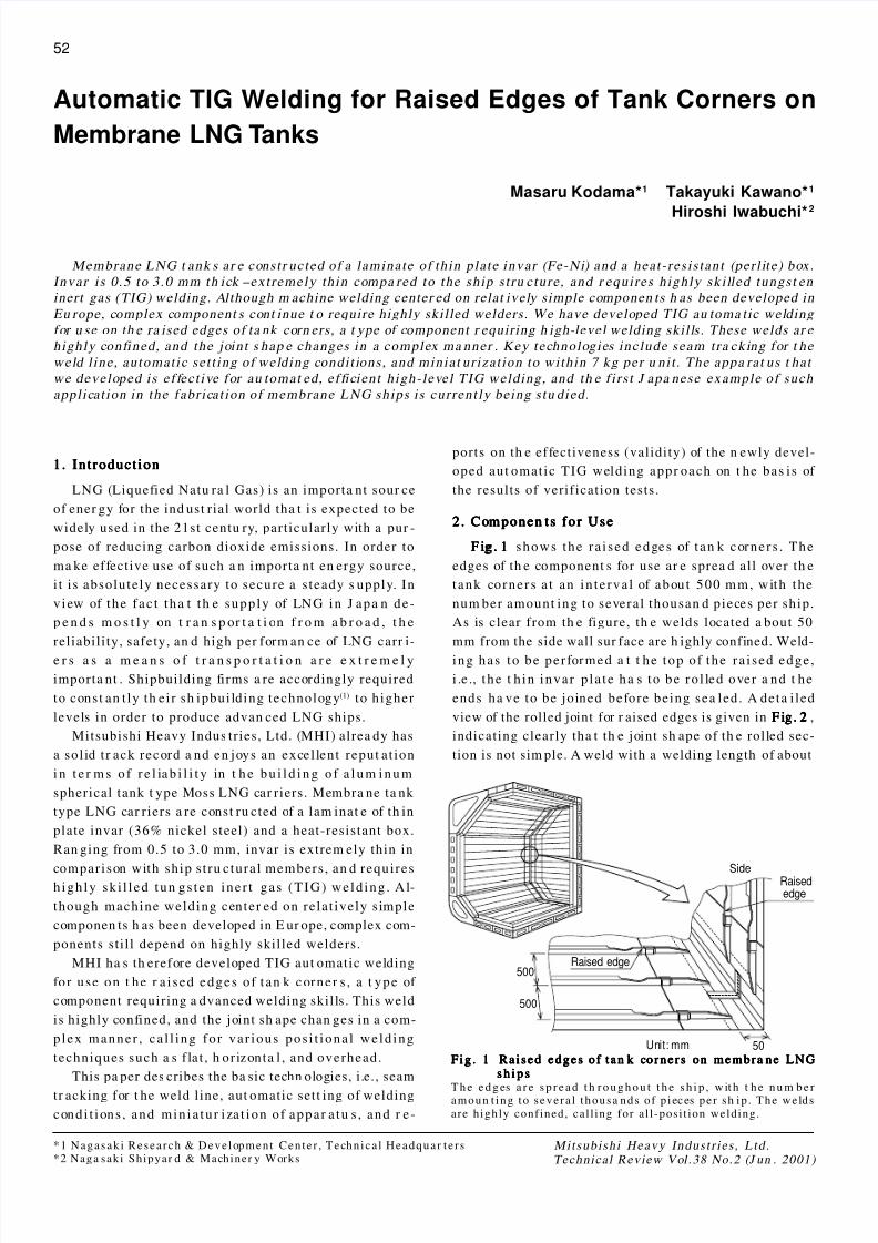
2. Componen ts for Use2. Componen ts for Use2. Componen ts for Use2. Componen ts for Use2. Componen ts for Use
F igF igF igF igF ig . 1. 1. 1. 1. 1 shows the r a i sed edges of t an k corner s . The
edges of th e component s for use ar e sprea d all over th e
tank corner s a t an in t e rva l of about 500 mm, with the
num ber amount ing to several thousan d pieces per ship.
As is clear from th e figure, th e welds located a bout 50
mm from the side wall sur face are h ighly confined. Weld-
ing has to be per formed a t t he top of the r a i sed edge ,
i .e ., t he t h in invar p l a t e ha s to be ro l led over a nd t he
ends ha ve to be joined before being sea led. A deta i led
view of the rolled joint for r aised edges is given in F igF igF igF igF ig . 2. 2. 2. 2. 2 ,
indicating clearly tha t th e joint sh ape of th e rolled sec-
tion is not sim ple. A weld with a welding length of about
500
500
50
Side
Raised edge
Raisededge
Unit: mm
Fig . 1 Ra i se d e d g e s o f t a n k co r n e r s o n m e m b r a n e L NGFig . 1 Ra i se d e d g e s o f t a n k co r n e r s o n m e m b r a n e L NGFig . 1 Ra i se d e d g e s o f t a n k co r n e r s o n m e m b r a n e L NGFig . 1 Ra i se d e d g e s o f t a n k co r n e r s o n m e m b r a n e L NGFig . 1 Ra i se d e d g e s o f t a n k co r n e r s o n m e m b r a n e L NGs h i p ss h i p ss h i p ss h i p ss h i p s
T h e e d g es a r e s p r e a d t h r o u g h o u t t h e s h i p , w it h t h e n u m b e ramoun t ing to s evera l thousa nds of p ieces pe r sh ip . The we lds
are highly confined, cal l ing for a l l -pos i t ion welding.
8/2/2019 Automatic TIG Welding for Raised Edges of Tank Corners on Membrane LNG Tanks
http://slidepdf.com/reader/full/automatic-tig-welding-for-raised-edges-of-tank-corners-on-membrane-lng-tanks 2/5
Weld Weld
t 1.5
t 0.7
t 0.7
t 0.5
t 1.5
0.7 0.7 1.5
0.7 0.7
1.5 1.51.50.5
0.5
1 4 0 3 0
4 0 0 5 0
Unit: mm
Five-ply Two-plyThree-ply
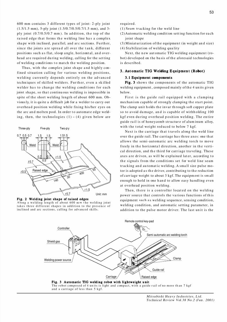
Raised edge
Controller
Shield gas
Welding power source
Carriage Raised edge
Guide rail
Clamp
Semi-automatic arc welding torch
Remote control key-pad
M itsu b ish i He a v y I n d u s t r i e s , L td .Technical Review Vol.38 No.2 (J un . 2001)
53
600 mm contains 3 different types of joint: 2-ply joint
(1.5/1.5 mm), 5-ply joint (1.5/0.7/0.5/0.7/1.5 mm), and 3-
ply joint (0.7/0.5/0.7 mm ). In ad di t ion, th e top of the
ra ised edge th at forms th e welding l ine ha s a complex
sha pe with inclined, para llel, and ar c sections. Fu rth er,
since the joints a re sprea d al l over the t an k, di fferent
posit ions such a s f lat , sloop a ngle, horizont al , an d over-
head ar e required du ring welding, call ing for the set t ing
of welding condit ions t o mat ch th e welding posit ion.
Thus, wi th the complex joint sh ape a nd h ighly con-
f ined si tuat ion cal l ing for var ious welding posi t ions,
weld ing cur ren t ly depends en t i r e ly on the advanced
techn iques of ski l led welders. Fur th er , even a sk i l led
welder ha s to chan ge the welding condi t ions for each
joint sha pe, so tha t continu ous welding is impossible in
spite of th e short welding lengt h of about 600 mm. Ob-
vious ly, it is qu ite a difficult job for a welder t o car ry out
overhea d posit ion welding while f ixing his/her eyes on
the arc an d molten pool. In order t o automat e edge weld-ing , t hen , t he t echnologies (1) - (4) given below are
required.
(1) Seam tr acking for t he weld l ine
(2) Automa tic welding condit ion sett ing function for ea ch
joint shape
(3) Miniat ur ization of th e equipmen t (in weight an d size)
(4) Sta bil izat ion of welding qua li ty
Next, the n ew aut omatic TIG welding equipmen t (ro-
bot) developed on t he ba sis of th e aforesaid t echnologies
is described.
3. Aut omat ic TIG Welding E quipmen t (Robot)3 . Aut omat ic TIG Welding E quipmen t (Robot)3 . Aut omat ic TIG Welding E quipmen t (Robot)3 . Aut omat ic TIG Welding E quipmen t (Robot)3 . Aut omat ic TIG Welding E quipmen t (Robot)
3.1 Equipment component s3 .1 Equipment component s3 .1 Equipment component s3 .1 Equipment component s3 .1 Equipment component s
Fig. 3Fig. 3Fig. 3Fig. 3Fig. 3 shows the components of the automat ic TIG
welding equipment , composed mainly of th e 4 un its given
below.
F i r s t i s t he gu i de r a i l equ i pped w it h a c l am p i ng
mechan ism capable of strongly clamping th e sta rt point.
The clamp unit h olds th e invar th rough soft copper plate
so to avoid da mage, an d is capable of wi thh olding 100kgf even du r ing overhead p osit ion welding. The en t i re
guide ra il is of honeycomb str uctur e of alum inum alloy,
with t he t otal weight red uced to below 7 kgf.
Next i s the car r iage th at t ravels along th e weld l ine
over th e guide rail . The carriage ha s th ree axes: one th at
al lows the semi-automat ic arc welding torch to move
freely in th e hor izonta l di rect ion, another in th e ver t i -
cal direction, and th e th ird for carr iage tra veling. These
axes a re dr iven, as will be explained lat er , according t o
th e signals f rom the condi t ions set for weld l ine seam
tr acking an d au tomat ic welding. A sma ll size pulse mo-
tor is adopted a s th e driver, contributing to th e reduction
of carr iage weight to about 3 kgf. The equipm ent is sm all
enough to hold in one h an d to allow easy ha ndling even
at overhead posit ion welding.
Then, th ere i s a cont ro l le r l oca t ed on the weld ing
power source tha t controls the va rious functions of th is
equipment such a s welding sequence, sensing condition,
welding condition, and automatic sett ing parameter, in
addi t ion to the pulse motor dr iver. The last un i t i s the
Fig . 2 Weld ing jo in t sha pe of ra ised edgesFig . 2 Weld ing jo in t sha pe of ra ised edgesFig . 2 Weld ing jo in t sha pe of ra ised edgesFig . 2 Weld ing jo in t sha pe of ra ised edgesFig . 2 Weld ing jo in t sha pe of ra ised edgesA lo n g a w e l d i n g l e n g t h o f a b o u t 6 0 0 m m t h e w e l d i n g j oi n t
t a k e s t h r e e d i f f e r e n t s h a p e s i n a d d i t i o n t o t h e p r e s e n c e o f incl ined and arc sect ions , cal l ing for advanced ski l ls .
Fig . 3 Au to m a t i c TI G we ld in g r o b ot w i th l i g h twe ig h t u n i tF ig . 3 Au to m a t i c TI G we ld in g r o b ot w i th l i g h twe ig h t u n i tF ig . 3 Au to m a t i c TI G we ld in g r o b ot w i th l i g h twe ig h t u n i tF ig . 3 Au to m a t i c TI G we ld in g r o b ot w i th l i g h twe ig h t u n i tF ig . 3 Au to m a t i c TI G we ld in g r o b ot w i th l i g h twe ig h t u n i tThe robot composed of 4 un i t s i s l i gh t and compac t , w i th a gu ide r a i l o f no more th an 7 kgf and a ca r r i age of l e s s than 5 kgf .
8/2/2019 Automatic TIG Welding for Raised Edges of Tank Corners on Membrane LNG Tanks
http://slidepdf.com/reader/full/automatic-tig-welding-for-raised-edges-of-tank-corners-on-membrane-lng-tanks 3/5
Mitsub ish i Heavy Indust r ies , L td .Technical Review Vol.38 No.2 (J un . 2001)
54
remote control key-pad, which a l lows th e inpu t of pa-
ra met ers before welding. The remote control key-pad can
also be used to operat e the welding posit ion man ua l ly
and to chan ge the welding condi t ion pa ram eters, whi le
moni tor ing th e welding sta te du r ing welding.
As for the welding sequence, the required pa ram eters
of welding and sen sing conditions ar e input in adva nce
before fixing th e guide rail to the edge an d th e carriage
to the guide rai l . Next , EXECUTE is selected f rom the
remote contr ol key-pad t o move the equipmen t a utomat i-
cally to th e welding sta rt point before coming t o a stop.
Similar ly, on r eceiving th e WELDING START comma nd
from th e remote contr ol key-pad, th e equipment star ts
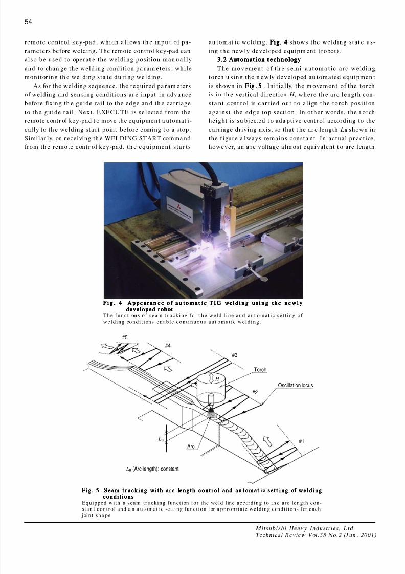
#5
#4
#3
#2
#1
La (Arc length): constant
La
H
Torch
Oscillation locus
Arc
au tomat ic welding. Fig. 4Fig. 4Fig. 4Fig. 4Fig. 4 shows the welding stat e us-
ing th e newly developed equipm ent (robot) .
3.2 Automat ion techn ology3.2 Aut omat ion t echnology3.2 Automat ion techn ology3.2 Aut omat ion t echnology3.2 Aut omat ion t echnology
The movement of th e semi -automa t i c a r c weld ing
torch u sing the n ewly developed au tomated equipmen t
is shown in F igF igF igF igF ig . 5. 5. 5. 5. 5 . Ini t ial ly, the m ovement of the torch
is in th e vertical direction H , where th e arc length con-
sta nt cont rol is car r ied out t o al ign t he torch posi t ion
against the edge top sect ion. In other words, the t orch
height is su bjected t o ada ptive cont rol according to the
carriage driving axis, so that t he ar c length La shown in
the f igure a lways remains consta nt . In actual pr act ice,
however, an a rc voltage alm ost equivalent t o arc length
F i g . 4 A p p e a r a n c e o f a u t o m a t i c T I G w el d i n g u s i n g t h e n e w l yF i g . 4 A p p e a r a n c e o f a u t o m a t i c T I G we l d i n g u s i n g t h e n e w l yF i g . 4 A p p e a r a n c e o f a u t o m a t i c T I G w el d i n g u s i n g t h e n e w l yF i g . 4 A p p e a r a n c e o f a u t o m a t i c T I G we l d i n g u s i n g t h e n e w l yF i g . 4 A p p e a r a n c e o f a u t o m a t i c T I G w el d i n g u s i n g t h e n e w l ydeveloped robo tdeveloped r obotdeveloped robo tdeveloped r obotdeveloped robo t
The func t ions of s eam t r ack ing for t he we ld l ine and au t omat i c s e t t ing of we ld ing condi t ions enable cont inuous au t omat i c we ld ing .
Fig . 5 Se a m t r a c k in g w i th a r c le n g th c o n t r o l a n d a u to m a t i c se t t i n g of we ld in gF ig . 5 Se a m t r a c k in g w i th a r c le n g th c o n t r o l a n d a u to m a t i c se t t i n g of we ld in gF ig . 5 Se a m t r a c k in g w i th a r c le n g th c o n t r o l a n d a u to m a t i c se t t i n g of we ld in gF ig . 5 Se a m t r a c k in g w i th a r c le n g th c o n t r o l a n d a u to m a t i c se t t i n g of we ld in gF ig . 5 Se a m t r a c k in g w i th a r c le n g th c o n t r o l a n d a u to m a t i c se t t i n g of we ld in gc o n d i t i o n sc o n d i t i o n sc o n d i t i o n sc o n d i t i o n sc o n d i t i o n s
Equipped with a seam tr acking funct ion for the weld l ine according to th e arc length con-s tan t control and a n a utomat ic set t ing funct ion for a ppropriate welding condi t ions for each joint sha pe
8/2/2019 Automatic TIG Welding for Raised Edges of Tank Corners on Membrane LNG Tanks
http://slidepdf.com/reader/full/automatic-tig-welding-for-raised-edges-of-tank-corners-on-membrane-lng-tanks 4/5
Table 1 Fu nctions of the newly developed automat ic TIGTable 1 Fu nctions of the newly developed au toma tic TIGTable 1 Fu nctions of the newly developed automat ic TIGTable 1 Fu nctions of the newly developed au toma tic TIG
welding robot for r aised edgeswelding robot for r aised edgeswelding robot for r aised edgeswelding robot for r aised edges
Feat ur es Fun ction Effect
Arc length
constant control
(Arc volta ge
consta nt contr ol)
Arc length (Arc voltage) is kept
constant against the
two-dimensional weld line
Heat input constant
→ Stable weld penetra tionAutomatic
function
Automatic setting
of welding
conditions
Detects the position of jointchange and automatically sets
the welding conditions for each
joint
Continuous welding
→ Excellent workability
Light and
small
(Miniaturi-
zation)
Weight:
below 7
kgf/component
Excellent portability, and can be
easily fixed even in th e overhead
position by mea ns of clam ping
mechanism
Light → Excellent workability
Stable
qualityArc oscillation
Ensures substan tial penetration
on both sides of the joint.
Ensures stability of penetration
radius R (standard).
M itsu b ish i He a v y I n d u s t r i e s , L td .Technical Review Vol.38 No.2 (J un . 2001)
55
La i s detected to calculate t he deviat ion by compa r ing
the a c tua l a r c vol t age with the pr ese t appropr i a t e a r c
voltage. On t he ba sis of this deviation, th e vertical drive
axis of th e torch in th e car riage is operated t o car ry out
feedback cont rol of th e torch he ight. As sh own in Fig. 5,
this ena bles seam t racking of the torch a gainst th e ver-
t ical cha nge of th e edge weld as wel l , ensur ing sta ble
penetra t ion qual i ty.
The next r equi r ed i t em i s th e au t omat i c set t ing of
welding conditions again st t he chan ge in joint sh ape. In
convent iona l welding, a welder ha s to stop welding to
reset t he welding condit ions every t ime th e joint sh ape
is chan ged. This problem was s olved in th e fol lowing
man ner wi th t he n ewly developed equipment (robot ) .
Mark ers ar e inst alled in adva nce along the guide rail at
places where t he welding conditions need to be chan ged.
T hese m ar ke r s a r e t hen de t ec t ed when t h e ca r r i age
pas ses over them t o inform t he us er of chan ges in joint
sha pe or th e places for cha nging th e welding conditions.
On receiving the mar ker detecting signal, th e appropri-
at e welding conditions corres ponding to th at pa rticular
joint ar e called up to keep th e welding going. As sh ownin F ig. 5, f ive welding cond itions from #1 t o #5 ar e set
for a shor t weld ing d i s t ance of about 600 mm. Thi s
means that edge welding cannot be done successively
un less the welding condi t ions a re divided elaborat ely
into sma ll parts . Of th e various welding conditions, th e
oscil lation condit ion of th e welding ar c is th e most im-
p o r t a n t p a r a m e t e r . I t i s n e c e s s a r y t o c h a n g e t h e
oscil lat ion speed, stop t ime a t both ends, welding speed,
etc. simu ltan eously for each joint sh ape. These welding
condi t ions a re deduced in advan ce as th e appr opr i a t e
welding cond itions for ea ch welding posit ion. The fea-
tur es of the newly developed welding equipment and th e
effects ther eof are sum mar ized in TTTTTable 1able 1able 1able 1able 1.
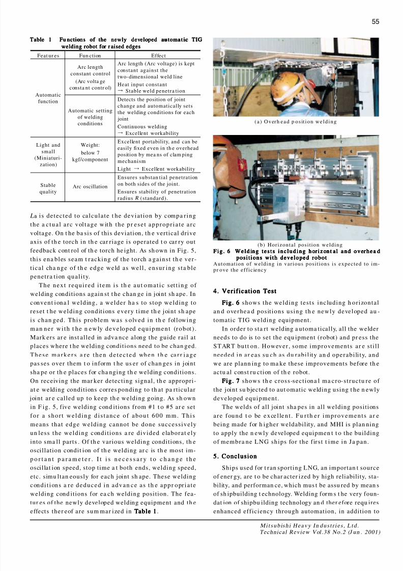
4. Verif ication Test4. Verif ication Test4. Verif ication Test4. Verif ication Test4. Verif ication Test
Fig. 6Fig. 6Fig. 6Fig. 6Fig. 6 shows the welding tests including h or izontal
an d overhea d posit ions using th e newly developed au -
tomatic TIG welding equipment.
In order to sta rt welding a utoma tically, al l the welder
needs to do is to set the equ ipment (robot) and pr ess the
START but t on. However , some improvements ar e st i l l
needed in ar eas su ch as du rabi l ity an d operabi li ty, and
we are plann ing to ma ke these improvements before th e
actu al const ru ction of th e robot.
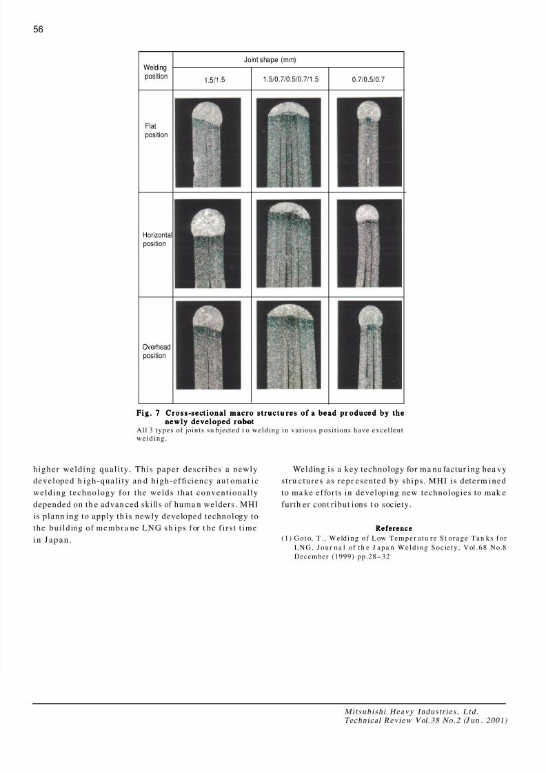
Fig. 7Fig. 7Fig. 7Fig. 7Fig. 7 shows th e cross-sect iona l ma cro-st ructu re of
the joint su bjected to aut omatic welding using t he n ewly
developed equipment .The welds of all joint sha pes in all welding posit ions
are found t o be exce l len t . Fu r th er improvement s a r e
being made for h igher weldability, and MHI is plan ning
to apply the n ewly developed equipmen t t o the building
of membra ne LNG ships for the f ir st t ime in Ja pan.
5. Conclusion5. Conclusion5. Conclusion5. Conclusion5. Conclusion
Ships used for t ran sporting LNG, an importan t source
of ener gy, are t o be char acter ized by high reliability, sta-
bility, and performan ce, which mus t be assu red by mean s
of sh ipbuilding t echnology. Welding form s t he very foun-
dat ion of shipbu ilding technology an d ther efore requ ires
enhanced efficiency through automation, in addition to
(a ) Overh ead p os it ion we ld ing
(b) Horizontal pos i t ion welding
Fig . 6 We ld in g t e s t s i n c lu d in g h or i z on t a l a n d o v er h e a dF ig . 6 We ld in g t e s t s i n c lu d in g h or i z on t a l a n d o v er h e a dF ig . 6 We ld in g t e s t s i n c lu d in g h or i z on t a l a n d o v er h e a dF ig . 6 We ld in g t e s t s i n c lu d in g h or i z on t a l a n d o v er h e a dF ig . 6 We ld in g t e s t s i n c lu d in g h or i z on t a l a n d o v er h e a dposi t ions wi th developed robo tposi t ions wi th developed robo tposi t ions wi th developed robo tposi t ions wi th developed robo tposi t ions wi th developed robo t
Automation of welding in various pos i t ions is expected to im-pr ove the eff ic iency
8/2/2019 Automatic TIG Welding for Raised Edges of Tank Corners on Membrane LNG Tanks
http://slidepdf.com/reader/full/automatic-tig-welding-for-raised-edges-of-tank-corners-on-membrane-lng-tanks 5/5
Weldingposition
Joint shape (mm)
Overheadposition
Horizontalposition
Flat
position
1.5 /1.5 1.5/0.7/0.5/0.7/1.5 0.7/0.5/0.7
Mitsub ish i Heavy Indust r ies , L td .Technical Review Vol.38 No.2 (J un . 2001)
56
Fig . 7 Cr o ss -se ct io n a l m a c r o s t r u c tu r e s o f a b e a d p r o d u ce d b y th eF ig . 7 Cr o ss -se ct io n a l m a c r o s t r u c tu r e s o f a b e a d p r o d u ce d b y th eF ig . 7 Cr o ss -se ct io n a l m a c r o s t r u c tu r e s o f a b e a d p r o d u ce d b y th eF ig . 7 Cr o ss -se ct io n a l m a c r o s t r u c tu r e s o f a b e a d p r o d u ce d b y th eF ig . 7 Cr o ss -se ct io n a l m a c r o s t r u c tu r e s o f a b e a d p r o d u ce d b y th enewly developed robo tnewly developed r obotnewly developed robo tnewly developed r obotnewly developed robo t
All 3 types of joints su bjected t o welding in various p ositions have excellentwelding.
higher welding qual i ty. This paper descr ibes a newly
developed h igh-qual i ty an d high-efficiency aut omat ic
welding technology for the welds that convent ional ly
depended on th e advan ced skills of huma n welders. MHI
is plann ing to apply th is newly developed technology to
the bui lding of membra ne LNG sh ips for t he f i r st t ime
i n J apan .
Welding is a key technology for ma nu factur ing hea vy
st ru ctures as repr esented by ships. MHI is determ ined
to ma ke efforts in developing new technologies to mak e
furth er cont ribut ions t o society.
Refe renceRefe renceRefe renceRefe renceRefe rence
(1) Goto, T . , Weld ing of Low Temper a tu re S t orage Tan ks forLNG, Jour na l o f th e J apa n Weld ing Soc ie ty , Vol .68 No.8
December (1999) pp.28-32