automotive biw line cycle time reduction
TRANSCRIPT
International Research Journal of Engineering and Technology (IRJET) e-ISSN: 2395-0056
Volume: 08 Issue: 10 | Oct 2021 www.irjet.net p-ISSN: 2395-0072
© 2021, IRJET | Impact Factor value: 7.529 | ISO 9001:2008 Certified Journal | Page 361
Automotive BIW line Cycle time reduction
Akshay Dudam
B.E. Mechanical Engineering, ISB&M Pune, Maharashtra, India ---------------------------------------------------------------------***----------------------------------------------------------------------Abstract - Cycle time is the most important factor in the manufacturing industry to improve efficiency, Productivity & to reduce the overall cost. In Automotive line assembly every robot has to perform its task in its prescribed time to achieve the cycle time. Robot idle time should be as less as possible. Sometimes we have to move the resources/tools position in the layout in order to reduce cycle time. In our project the robot has 2 functions to do – 1. To pick and drop the car part and 2. To weld the car part. So In this case study we have mounted both gripper as well as gun on same Robot with the help of designing an intermediate tool. The gripper is used to pick & drop the car part and after dropping the panel the same robot welds the car part which results in shortening of the cycle time.
Key Words: Automotive assembly Line, Spot welding, Cycle time, Robotic simulation, Workstation, Idle time, Productivity.
1. INTRODUCTION The main aim of the project is to reduce the cycle time of the process and to increase the productivity. Productivity is nothing but the numbers of jobs produced per day. It is achieved by properly balancing the line and reducing the idle time of robots by studying and analyzing the layout and process flow. Finally producing more output by reducing the cycle time will result in increased productivity. Productivity is also defined as the ratio of output and input. Whereas output means the number of jobs produced and input means the various resources like machines, man hours, robots, material, money etc. Cycle time is the total time taken to complete all the sequential process which takes place on recurring basis in an assembly line. The cycle time is used to measure the productivity of each workstation. So the workstation with longest cycle time is of very critical process. This result in the overall output of jobs produced per day. So the productivity can be increased only if we reduce the cycle time of the longest operation in an assembly line.
2. PROBLEM DEFINITION
This study is focused to reduce the cycle time of the line. The Robot has to pick car part and drop on fixture after that it has to dock the gripper on gripper stand, pick the gun from gun stand and start welding of car parts. But the whole process was taking a lot of time near about 85 sec for the robot to complete the task. Due to this other robots which has less cycle time has to wait for this robot to complete the operation. This was leading in increase in cycle time and reduction in productivity.
3. METHOD STUDY IMPLICATION Step 1: Determined the sequence of operations performed by the Robot and calculated the cycle time or each operation and overall process. Step 2: Studied the process and layout of the plant checked for optimization of the process by shifting the tools or adding/deleting the tools. Checked for the bottleneck situation in the process. Step 3: After Studying the process and layout of the plant it was found that it was possible to mount gripper and gun on same robot with the help of intermediate tool so that the time taken by robot to pick/drop the gripper and pick/drop the gun is avoided. Hence reducing the cycle time of the Robot and increasing the productivity & increase the number of output car parts. Step 4: Placed the resources in the layout according to the new concept. Step 5: Designed the new intermediate tool for mounting the gripper and welding gun on it. Step 6: Checked for Robot payload and robot validation for reachability of the robot for all the processes. Step 7: Checked for design and manufacturability of all parts of the tools.
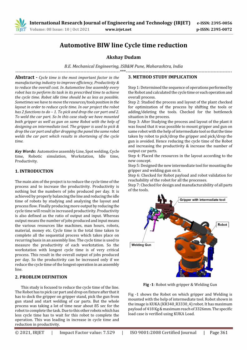
Fig -1: Robot with gripper & Welding Gun
Fig -1 shows the Robot on which gripper and Welding is mounted with the help of intermediate tool. Robot shown in the image is KUKA (KR340_R3330_4) robot. It has maximum payload of 418 Kg & maximum reach of 3326mm. The specific load case is verified using KUKA Load.
International Research Journal of Engineering and Technology (IRJET) e-ISSN: 2395-0056
Volume: 08 Issue: 10 | Oct 2021 www.irjet.net p-ISSN: 2395-0072
© 2021, IRJET | Impact Factor value: 7.529 | ISO 9001:2008 Certified Journal | Page 362
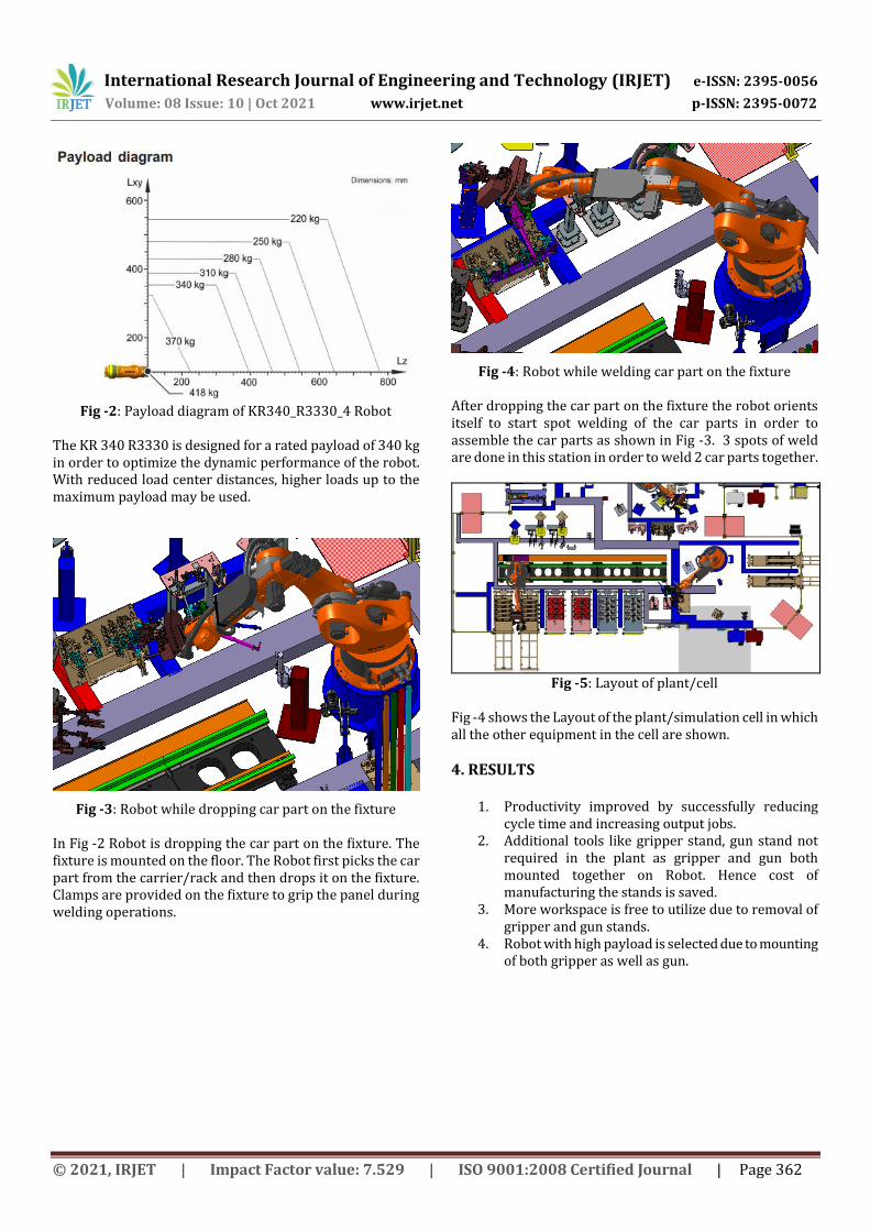
Fig -2: Payload diagram of KR340_R3330_4 Robot
The KR 340 R3330 is designed for a rated payload of 340 kg in order to optimize the dynamic performance of the robot. With reduced load center distances, higher loads up to the maximum payload may be used.
Fig -3: Robot while dropping car part on the fixture
In Fig -2 Robot is dropping the car part on the fixture. The fixture is mounted on the floor. The Robot first picks the car part from the carrier/rack and then drops it on the fixture. Clamps are provided on the fixture to grip the panel during welding operations.
Fig -4: Robot while welding car part on the fixture
After dropping the car part on the fixture the robot orients itself to start spot welding of the car parts in order to assemble the car parts as shown in Fig -3. 3 spots of weld are done in this station in order to weld 2 car parts together.
Fig -5: Layout of plant/cell
Fig -4 shows the Layout of the plant/simulation cell in which all the other equipment in the cell are shown.
4. RESULTS
1. Productivity improved by successfully reducing cycle time and increasing output jobs.
2. Additional tools like gripper stand, gun stand not required in the plant as gripper and gun both mounted together on Robot. Hence cost of manufacturing the stands is saved.
3. More workspace is free to utilize due to removal of gripper and gun stands.
4. Robot with high payload is selected due to mounting of both gripper as well as gun.
International Research Journal of Engineering and Technology (IRJET) e-ISSN: 2395-0056
Volume: 08 Issue: 10 | Oct 2021 www.irjet.net p-ISSN: 2395-0072
© 2021, IRJET | Impact Factor value: 7.529 | ISO 9001:2008 Certified Journal | Page 363
5. CONCLUSIONS
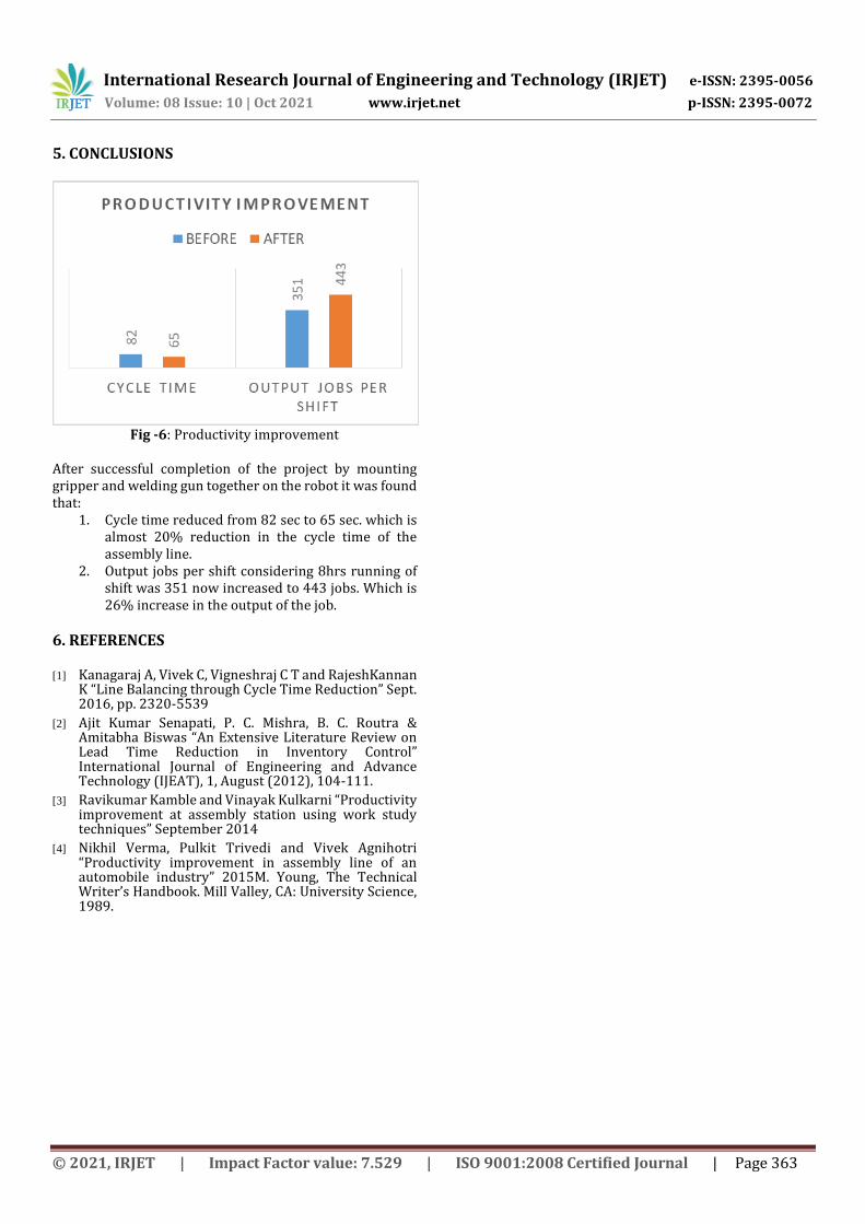
Fig -6: Productivity improvement
After successful completion of the project by mounting gripper and welding gun together on the robot it was found that:
1. Cycle time reduced from 82 sec to 65 sec. which is almost 20% reduction in the cycle time of the assembly line.
2. Output jobs per shift considering 8hrs running of shift was 351 now increased to 443 jobs. Which is 26% increase in the output of the job.
6. REFERENCES [1] Kanagaraj A, Vivek C, Vigneshraj C T and RajeshKannan
K “Line Balancing through Cycle Time Reduction” Sept. 2016, pp. 2320-5539
[2] Ajit Kumar Senapati, P. C. Mishra, B. C. Routra & Amitabha Biswas “An Extensive Literature Review on Lead Time Reduction in Inventory Control” International Journal of Engineering and Advance Technology (IJEAT), 1, August (2012), 104-111.
[3] Ravikumar Kamble and Vinayak Kulkarni “Productivity improvement at assembly station using work study techniques” September 2014
[4] Nikhil Verma, Pulkit Trivedi and Vivek Agnihotri “Productivity improvement in assembly line of an automobile industry” 2015M. Young, The Technical Writer’s Handbook. Mill Valley, CA: University Science, 1989.