b instructions for installation operation double...
TRANSCRIPT
Model DDX PrePaK, Type DPreaction System4”(100mm) & 6”(150mm)
Instructions forInstallation, Operation,Care and Maintenance10 psi (0,7 bar) Pneumatic Supervising Pressure
Single InterlockDouble Interlock
The Reliable Automatic Sprinkler Co., Inc. 103 Fairview Park Drive , Elmsford, New York 10523
Bulletin 733 Rev. B Bulle
tin733
Re
v.B

General DescriptionThe Reliable Model DDX 4” (100 mm) and 6” (150 mm)
PrePaKs are completely self-contained, supervisedpreaction systems that can be readily installed within a floorspace of 4.7 ft2 (0.44 m2) (not including door swing).Installation of the PrePaK (not including exterior devices,i.e., detectors and alarm bells), requires just three pipingconnections: a 4” (100 mm) or 6” (150 mm) supply line, a 4”(100 mm) or 6” (150 mm) system line, and a 2” (50 mm)drain line. Reference locations of these piping connectionsare shown in Fig.1. Also, two 120 / 220 VAC electricalsupply connections are required. Note: The Model DDXPrePak is available with its air compressor and Potter ModelPFC-4410-RC Releasing/Control Panel wired for a 120 VAC/ 60Hz or for a 220 VAC / 50 Hz power supply.
The Reliable Model DDX PrePaK contains the followingcomponents within its 25.7” (0.65 m) W x 28.9” (0.73 m) D x68” (1.73 m) H 12-gauge steel enclosure:
• One Reliable Model DDX 4” (100 mm) or 6” (150 mm)Deluge Value with Type D Double Interlock PreactionTrim set (See Reliable Bulletin 728).
• One Gast Model 5HCD-108-M550NGX ¾ Hp AirCompressor (a 1½ Hp Model 7HDD-16-M750X, AirCompressor is optional in the 6” (150 mm) PrePaK only).
• One 8 gallon (30.3 liter) air tank.• One Potter Model PFC-4410-RC Releasing/Control
Panel (See Potter Manual #5403550).• One Pressure Maintenance Device for system air
supervision (contains regulator, check valve, strainer,and rapid-fill option).
• All required fittings, gauges, electrical connectors, andelectrical devices to utilize the system in single interlock,single interlock cross-zoned, double interlock, anddouble interlock cross-zoned applications.
The Reliable Model DDX PrePaK utilizes the Potter ModelPFC-4410-RC Releasing Control Panel. This fullyprogrammable, microprocessor-based releasing panel isUnderwriters Laboratories, Inc. Listed and is in compliancewith NFPA 13 and NFPA 72. Because the PFC-4410-RC istotally zone and output programmable, the Reliable ModelDDX PrePaK can be utilized in many different preactionapplications without having to rewire any of the factoryinstalled devices. Once the previously describedconnections are completed, the 24 VDC detectors, outputdevices, and relay contacts may be connected to achievethe desired system implementation.
The Model DDX PrePaK can be used in both single anddouble interlock applications. Reliable Single and DoubleInterlock Preaction Systems are designed for watersensitive areas that require protection from inadvertentwater flow into the sprinkler system piping.
The major benefits of a single/double interlock preactionSystem, when compared with a wet pipe system, are asfollows:A. A fire alarm sounds prior to the flow of water from a
sprinkler, which may enable extinguishing the fire byhandheld means before the operation of any sprinklerhead occurs.
B. An annunciator signals whenever the integrity of pipingor sprinklers is accidentally or intentionally disturbed;however, no water flow or water damage will result atthat time.
C. Speedy detection and an early fire alarm are providedby fire detectors, without the delay associated withwater delivery time in the event of a fire. Note that with a
wet pipe system, the fire alarm is delayed until afterwater has begun flowing from and operated sprinklerhead.
In single interlock applications, one electrical detectorsenses the presence of fire, thereby causing the electricalreleasing control panel to activate fire alarm devices andenergize the solenoid releasing valve in the open position.Note that arranging detectors in a cross-zoned pattern willrequire operation of two detectors before the solenoid valvecan open (Note: Cross-zoned detection systems are notpermitted in New York City and are not Factory MutualApproved). The solenoid valve, when closed, is preservingsupply water pressure in the deluge valve’s push-rodchamber. Actuating the solenoid valve releases that waterpressure which allows the valve to open.
To fully operate a single interlock system withcross-zoned detection, two separate electrical detectionsystems must activate and a sprinkler must open. Duringthe early stages of a fire, smoke or heat activates the firstdetector, which causes the control panel to produce a localalarm and an alarm at the main fire alarm panel. Electricalrelays inside the releasing control panel can be used toshut down air moving equipment or activate security doorsand other electrical devices when the panel goes into thisfirst condition. Subsequent activation of a second, nearbyor adjacent detector, on a separate detection system, willcause the panel to energize the solenoid valve open andrelease water into the sprinkler piping. Water flowing intothe sprinkler piping will simultaneously produce waterpressure that causes the transfer of contacts in the alarmpressure switch mounted in the riser assembly, therebyactivating a water flow alarm device. The flow of water intothe sprinkler piping effectively converts the dry system intoa wet pipe system. In the event the fire subsequentlyproduces sufficient heat to operate a sprinkler head, waterwill flow from that sprinkler, controlling the fire.
To flow water into a double interlock preaction system,two events must take place. A fire detection device mustoperate, and a pressure switch must be operated by theloss of system pressure (sprinkler operation). These twosignals, both an electric signal and a pneumatic signal,must coexist at the releasing control panel, which only thenwill energize the solenoid releasing valve, causing waterflow into the sprinkler system and out of the opensprinkler(s).
In the event that the system piping is ruptured or asprinkler head is accidentally opened, the system pressureswitch will operate and an alarm will sound. The riserassembly, however, will not release water since thesolenoid valve remains closed due to only one input into thereleasing control panel.
When using the Reliable Model DDX PrePaK, in eithersingle or double interlock applications, the sprinkler systemis pressurized (supervised) with air provided by the aircompressor and is monitored by a system pressure switch.
A Model B Hydraulic Manual Emergency Releasingstation is standard equipment in the Model DDX PrePaK. Itconsists of an aluminum nameplate mechanically attachedto a ball valve. The valve handle in its OFF position isguarded against accidental turning to the ON position (andsystem discharge) by a nylon cable tie provided with thePrePaK assembly. The cable tie is designed to allow, incase of an emergency, forceful turning of the valve handleto the ON position.
2.

3.
Fig. 1

Approvals1. Underwriters Laboratories, Inc. Listed and Certified for
Canada* (cULus) as an assembled unit in the “SpecialSystem Water Control Valves Assembled Units”category, (VKYL).
2. Factory Mutual (FM) Approved, as PrePak SingleInterlock and Double Interlock Preaction Systems.
*Electrical devices and control panel must be specified tomeet Canadian requirements. This option is available.
3. NYC MEA 258-93-ENote: Although PrePak units are UL Listed, custom built
units are sometimes supplied upon request. Thecomponents within these special units maintain theirindividual Listings/Approvals, whereas the assembledunits do not.
PrePak units are also available without theirdoor-mounted Potter PFC-4410-RC Releasing/ ControlPanel and Air Compressor. These units will still retain theirListings/Approvals, however the installing contractorshould make sure that any remote controlledReleasing/Control Panels used with these units areListed/Approved and programmed to handle the requiredsequence of operation necessary to operate the automaticsprinkler system. Any unauthorized modification oraddition made on-site to a factory-built Listed/Approvedunit will void the Listing/Approval. Such modifications oradditions may void the unit’s warranty as well. ConsultReliable’s Technical Services Department beforeproceeding with any such modifications or additions.
Technical Data1. The Reliable Model DDX 4” (100 mm) and 6” (150 mm)
PrePaKs are rated for a minimum supply pressure of 20psi (1,4 bar) and a maximum supply pressure of 250 psi(17,2 bar). Note: 1 bar = 100 kPa.
2. Friction loss, expressed in equivalent length ofSchedule 40 pipe and based on Hazen-WilliamsFormula with C=120 and a flowing velocity of 15 ft/s (4.6m/s), is:
4” (100 mm) - 58 ft. (17.7 m)6” (150 mm) - 71.4 ft. (21.8 m)
These values account for the Model DDX Deluge Valve,supply manifold tee, butterfly control valve, and smallpipe/manifold located directly above Model DDXDeluge Valve.
3. Shipping Weight: 4” (100 mm) - 680 lbs (308 kg)6” (150 mm) - 770 lbs (349 kg)
Dimensions: 25.7” W x 28.9” D x 68” H(0.65 m W x 0.73 m D x 1.73 m H)
(Refer to Fig. 1 for additional dimensions)
4. Grooved end connections:
The following is a list of Technical Data Bulletins whichdescribe the valves and devices which are used in thesystem:
Deluge Valve 510/511Type D Double Interlock Preaction Trim 728Low Air Pressure Switch System Sensor, A05-0176Hydraulic Emergency Station (Model A) 506Mechanical Sprinkler Alarm 612/613Solenoid Valve 718Alarm Pressure switch System Sensor, A05-0176Control Panel Potter Manual #5403550Detectors 722Fire Alarm Devices 700
The following table provides a quick reference to variousprograms (found in this bulletin and the Potter Manual#5403550) that may be utilized with a Model DDX PrePaK:
System Design ConsiderationsThe automatic sprinklers, releasing devices, fire detection
devices, manual pull stations, and signaling devices whichare utilized with the Reliable Model DDX 4” (100 mm) and6” (150 mm) PrePaKs must be UL and/or ULC Listed or FMApproved, as applicable.
The steel enclosure and all the interconnecting pipingmust be located indoors in a readily visible and accessiblelocation and in an area that can be maintained at aminimum temperature of 40�F (4�C). Note: Heat tracing isnot permitted. The solenoid valve is operated andsupervised by the Potter Model PFC-4410-RC ReleasingControl Panel. Details on the electrical connections of thissystem to the Potter Panel can be found in the PotterManual #5403550, Installation, Operation and Instruction ofPFC-4410-RC Releasing Control Panel (this manual isincluded with other pertinent manuals and shipped insidethe enclosure). This panel is fully zone and outputprogrammable and may be adapted to severalapplications.
4.
Groove Dimensions (Supply Manifold)
Pipe Size OutletDiameter
GrooveDiameter
GrooveWidth
Outlet Faceto Groove
4"(100mm)
4.500"(114mm)
4.334"(110mm) 3/8"
(10mm)5/8"
(16mm)6"(150mm)
6.625'(168mm)
6.455"(164mm)
Groove Dimensions (Drain Manifold)
Pipe Size OutletDiameter
GrooveDiameter
GrooveWidth
Outlet Faceto Groove
2"(50mm)
2.375"(60mm)
2.250"(57mm)
5/16"(8mm)
5/8"(16mm)
DesiredApplications (1) Description Program
No.
Single InterlockSingle Hazard, 2 Alarm Zoneswith 1 Waterflow Zone and 2Supervisory Zones
PotterProgram #6
CustomProgram #1
(NYC)
Single Interlock,Cross-Zoned
Single Hazard, Cross-Zoned, 2Alarm Zones with 1 waterflowZone and 2 Supervisory Zones
PotterProgram #7(2)
(1)Refer to Potter Manual # 5403550 included with the PrePak, for other
programming options available.(2)
Factory Program setting

System Supervising Pressure RequirementsIn accordance with NFPA 13, when using the Reliable
Model DDX 4” (100 mm) or 6” (150 mm) PrePaK in doubleinterlock applications, a minimum of 7 psi (0,5 bar)pneumatic pressure is required to supervise the sprinklersystem. When initially filling the system with air, theenclosure’s door should remain open in order to providemaximum intake air flow to the air compressor. The aircompressor is connected to an 8 gallon (30.3 liter) ASMErated storage tank. This tank functions as a reservoir,providing make-up air to compensate for small, intermittentleaks in the sprinkler system. It should be noted thatsignificant leaks may overburden this storage tank, therebycausing the air compressor to continuously cycle on andoff.
The Pressure Maintenance Device supplied with thesystem (refer to Fig. 8), is factory set to maintain systempneumatic pressure at approximately 10 psi (0,7 bar).Readjusting system pressure to approximately 10 psi (0,7bar), if necessary, is accomplished by first loosening thelocknut on the air pressure regulator and turning theadjustment screw (refer to Fig. 8). The system air pressuregauge that is attached to the vertical pipe/manifold(mounted directly above the Model DDX Deluge Valve)may be used to verify the correct level of pneumaticpressure.
The system air pressure switch (refer to Fig. 8) is factoryset to operate between 8 psi and 4 psi (0,6 bar and 0,3 bar)with decreasing pressure. Adjustment, if required, shouldbe made according to System Sensor Bulletin A05-0176included with the switch.
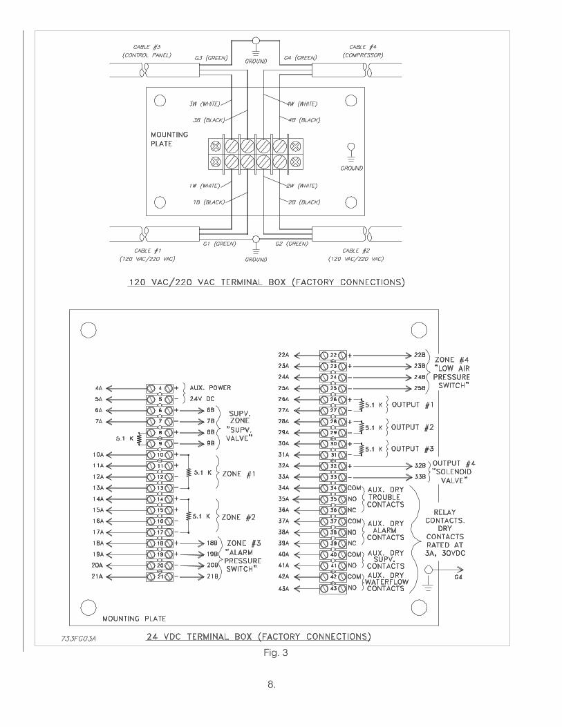
System Electrical RequirementsAll releasing, alarm, and detection devices in the Reliable
Model DDX 4” (100 mm) and 6” (150 mm) PrePaKs aresupervised by a Potter Model PFC-4410-RC ReleasingControl Panel. To utilize one of the doors of the steelenclosure as a mount for the releasing control panel, all ofthe terminals are translated to two, water-tight terminalboxes mounted on the interior of the enclosure. Note: theEOL (End of Line) resistors have also been relocated. It isfrom these terminal boxes that all field wiring is connected.There is one terminal box that contains the 24 VDCconnections and one that contains the 120 / 220 VACconnections. The Reliable Model DDX PrePaK is deliveredwith five factory-installed electrical devices. They consist ofthe following:1. A system air pressure switch, which is used to monitor
sprinkler piping.2. An alarm pressure switch, which indicates an actuation
of the deluge valve.3. A normally-closed, releasing solenoid valve, which is
used to actuate the deluge valve.4. A ¾ HP tank-mounted air compressor with 8 gallon
(30.3 liter) tank (1½ HP compressor is optional with 6”(150 mm) system only).
5. A supervised butterfly water control valve.
5.
The factory electrical connections of these devices areillustrated in Fig. 4. For information on how to install firedetection devices to initiating Zones 1 and 2 of the PotterModel PFC-4410-RC Releasing Control Panel, refer to Fig.5 or Fig. 6. For information on how to install output devices,i.e., alarm bells or trouble annunciators, to the Potter ModelPFC-4410-RC Releasing Control Panel, refer to Fig. 7. Thepower supply, standby emergency power supply, batterycharger and rectifier circuitry are all contained within thePFC-4410-RC panel. Batteries that provide 90 hours ofstandby power are provided with the panel. For additionalinformation and detailed wiring diagrams, refer to PotterManual #5403550, Installation, Operation and Instruction ofPFC-4410-RC Releasing Control Panel.
Caution: Repairs or disassembly of the solenoid valveshould only be done by a trained technician. Animproperly repaired or partially assembled solenoid valvecould result in failure of the valve to operate.
System Operation (Single Interlock)To fully activate (water flow) the Reliable Model DDX 4”
(100 mm) or 6” (150 mm) PrePaK in a single interlockapplication, a fire detection device (smoke, heat, etc.) (twodetectors with cross-zoned detection) must activate.Subsequently, a sprinkler head must open to dischargewater on the fire.
When the single interlock preaction system is set forservice, the supply pressure acts both on the underside ofthe deluge valve’s clapper and on the valve’s push rod bymeans of the pressurized push rod chamber. The pressureforce acting on the push rod, when utilized with themechanical advantage of the deluge valve’s lever, is morethan sufficient to hold the clapper in the closed positionagainst the water supply pressure.
Energizing the releasing solenoid valve allows the delugevalve’s push-rod chamber to be vented to drain through itsoutlet. Since the pressure cannot be replenished throughthe inlet restriction as rapidly as it is vented though theoutlet, the push-rod chamber pressure falls rapidly. Whenthe push-rod chamber pressure drops below one-third ofthe supply pressure, the opening force acting beneath theclapper becomes greater than the push-rod force actingon the lever. This causes the clapper to open. Refer toReliable Bulletins 510 and 511 for further details.
Once the clapper has opened, the lever acts as a latch,preventing the clapper from returning to the closedposition. Water from the supply flows through the delugevalve into the system piping. Water also flows through thedeluge valve alarm outlet to activate any water flow alarmdevices. Note that the solenoid valve will be maintainedopen by the Potter Model PFC-4410-RC Releasing ControlPanel’s latching feature until it is reset for operation.
After system shutdown and draining, the Model DDXDeluge Valve is easily reset without special tools (seeFig.8). Restore detection devices by resetting or replacingany operated device. Once detection devices are restored,(the Potter Model PFC-4410-RC Releasing Control Panelreset), and supply pressure is re-supplied to the push-rodchamber, the deluge valve is reset.

6.
System Operation (Double Interlock)To fully activate (water flow) the Reliable Model DDX 4”
(100 mm) or 6” (150 mm) PrePaK in a double interlockapplication, two independent events must coexist. Anelectrical fire detection device (smoke, heat, etc.) and thesystem air pressure switch must be activated. Thispressure switch is activated by a reduction of the system’spneumatic pressure (as a result of sprinkler operation).Both of these events will cause the control panel toenergize the solenoid valve, thereby releasing waterthrough the deluge valve and into the sprinkler system.The initiation of either one of these events will only cause analarm to annunciate, and will not fill the sprinkler system.
When the double interlock preaction system is set forservice, the supply pressure acts both on the underside ofthe deluge valve’s clapper and on the valve’s push rod bymeans of the pressurized push rod chamber. The pressureforce acting on the push rod, when utilized with themechanical advantage of the deluge valve’s lever, is morethan sufficient to hold the clapper in the closed positionagainst the water supply pressure.
Energizing the releasing solenoid valve allows the delugevalve’s push-rod chamber to be vented to drain through itsoutlet. Since the pressure cannot be replenished throughthe inlet restriction as rapidly as it is vented though theoutlet, the push-rod chamber pressure falls rapidly. Whenthe push-rod chamber pressure drops below one-third ofthe supply pressure, the opening force acting beneath theclapper becomes greater than the push-rod force actingon the lever. This causes the clapper to open. Refer toReliable Bulletins 510 and 511 for further details.
Once the clapper has opened, the lever acts as a latch,preventing the clapper from returning to the closedposition. Water from the supply flows through the delugevalve into the system piping. Water also flows through thedeluge valve alarm outlet to activate any water flow alarmdevices. Note that the solenoid valve will be maintainedopen by the Potter Model PFC-4410-RC Releasing ControlPanel’s latching feature until it is reset for operation.
After system shutdown and draining, the Model DDXDeluge Valve is easily reset without special tools (seeFig.8). Restore detection devices by resetting or replacingany operated device. Once detection devices are restored,(the Potter Model PFC-4410-RC Releasing Control Panelreset), and supply pressure is re-supplied to the push-rodchamber, the deluge valve is reset.
MaintenanceThe Reliable Model DDX PrePaK and associated
equipment shall periodically be given a thoroughinspection and test. NFPA 25, Inspection, Testing andMaintenance of water Based Fire Protection Systems,provides minimum maintenance requirements. Systemsshould be tested, operated, cleaned and inspected at leastannually, and parts replaced as required. Periodically openthe air/condensate drain valve (refer to Fig. 8) beneath theair tank to drain any condensate accumulation. Bulletin 510provides information for maintaining the Model DDXDeluge Valve. Potter Manual #5403550 providesinformation for maintaining the PFC-4410-RC ReleasingControl Panel.
Resetting Single And Double InterlockSystemsRefer to Fig. 8.1. Close the main valve controlling water supply to the
deluge valve and close the ¼” air shutoff valve, valve J.2. Close the pushrod chamber supply valve, valve A.3. Open the main drain valve, valve B, and drain system.4. Open all drain valves and vents at low points
throughout the system, closing them when flow ofwater has stopped. Open valve D. Note: The abovesteps accomplish the relieving of pressure in thepushrod chamber of the deluge valve.
5. Push in the plunger of ball drip valve, valve F, to forcethe ball from its seat, and drain any water in the alarmline.
6. With the Model B Manual Emergency Station, valve D,open, push in and rotate the deluge valve’s externalreset knob clockwise until you hear a distinct clickingnoise, indicating that the clapper has closed. Note:The reset knob can be rotated only after pressure in thepushrod chamber is reduced to atmosphericconditions (0 psig).
7. Inspect and replace any portion of the sprinkler systemsubjected to fire conditions.
8. Verify that the following valves are in their respectivepositions:valve C – open, valve E – closed, valve H – closed,valve K – open, valve M – closed.
9. Open valve A and allow water to fill the deluge valve’spushrod chamber. Close valve D.
10. Bleed any air from the actuation piping by energizingthe solenoid valve. This is done by operating adetector or an electric manual emergency station.While water is flowing through the solenoid valve,cause it to close by pressing the system reset buttonon the Potter PFC-4410-RC Releasing Control Panel.Note: All detection devices must be reset before thereleasing/control panel can be reset.
11. Open the ¼” air shutoff valve, valve J, to restore airpressure in the sprinkler system. The rapid air-fillshutoff valve, valve M, may be opened here toexpedite the filling of the sprinkler system.
12. Open slightly the main valve controlling water supply tothe Model DDX Deluge Valve, closing drain valve Bwhen water flows. Observe if water leaks through theball drip valve, valve F, into the drip cup, G. If no leakoccurs, the deluge valve’s clapper is sealed. Openslowly, and verify that the main valve controlling watersupply is fully opened and properly monitored.
13. Verify that valve A is open.14. Secure the handle of the Model B Manual Emergency
Station, valve D, in the OFF position with a nylon tie(supplied with the assembly).
15. Press the system reset button on the PotterPFC-4410-RC Panel to place the system in the readycondition. Note: All detection devices must be resetbefore the panel can be reset.

Fig. 2
7.
8.
Fig. 3

Fig. 4
9.

Fig
.5
10.

11.
Fig
.6

12.
Fig
.7

13.
Inspection And Testing Of Single AndDouble Interlock SystemsRefer to Fig. 8.1. Water supply — Verify that the valve controlling water
supply to the deluge valve is opened fully and properlymonitored.
2. Alarm line — Verify that valve C is opened andremains in this position.
3. Other trimming valves — Verify that valve A is openas well as all of the pressure gauge’s ¼” 3-way valves.Valves D, E, and H should be closed.
4. Ball drip valve F — Push in on the plunger to be surethe ball check is off its seat. If no water appears, thedeluge valve’s water seat is tight. Inspect the bleedhole in the front of the Model DDX Deluge Valve forleakage.
5. System pneumatic pressure — Verify that system airpressure is between 7 and 10 psi (0,5 bar 0,7 bar).Check the Pressure Maintenance Device for leakageand proper pressure.
6. Releasing device — Check the outlet of the releasingdevice (i.e., solenoid valve or the Model B ManualEmergency Station, valve D) for leakage. Also verifythat tubing drain lines from releasing devices are notpinched or crushed which could prevent properreleasing of the deluge valve.
7. Testing alarms — Open valve E permitting water fromthe supply to flow to the alarm pressure switch and tothe mechanical sprinkler alarm (if present). Aftertesting, close this valve completely. Push in on theplunger of ball drip valve F until all of the water hasdrained from the alarm line.
8. Operational test — Open the Model B ManualEmergency Station, valve D only, OR, operate thesolenoid valve by electrical actuation. This is done byoperating a detector or an electric manual emergencystation. Double interlock systems also require that thesprinkler system’s air pressure be discharged, throughthe inspectors test station or other venting means,below 4 psi (0,3 bar) before total system operation willoccur. Note: An operational test will cause the DelugeValve to open and flow water into the sprinkler system.
9. Secure the Model B Manual Emergency Station, valveD, in the OFF position with a nylon tie (included with theassembly) after the deluge valve is reset.
Testing The Model DDX PrePaK WithoutCausing Water FlowRefer to Fig. 8.1. Close the main valve controlling water supply to the
deluge valve and open drain valve B.2. Verify that valve A is open, allowing water to enter the
push-rod chamber.3. Operate the detection system - Operate a cross-zoned
releasing control panel by operating two detectors. Fordouble interlock applications, close valve J and openvalve H. Doing so will discharge the sprinkler system’sair pressure.
4. Step #3 should result in a sudden drop of waterpressure in the deluge valve’s push-rod chamber viaan energized solenoid valve.
5. Reset the detection system - Reverse the detectionsystem operations performed in Step #3 above. Note:All detection devices must be reset before the PotterPFC-4410-RC Releasing Control Panel can be reset.
6. Proceed according to the directions listed in the“Resetting Single And Double Interlock Systems”section of this bulletin.
Draining Excess/Condensate Water FromThe SystemRefer to Fig. 8.1. Close the main valve controlling water supply to the
deluge valve. Also, close valve A and open the maindrain valve, valve B.
2. Open the condensate drain valve, valve H, until all of thewater (if any) drains completely. Note: Be sure not tokeep valve H open for an extended period of timebecause that will cause enough system air to bleed off,thereby activating the system pressure switch andcausing an potentially undesirable alarm condition.
3. Close the main drain valve B. Allow the system’s airpressure to return to its previous level. Open valve Afirst, and then open the main valve controlling the watersupply to the deluge valve.

Fig. 8
14.

15.
Potter Program #6Single Interlock Programming Instructions(Single Hazard; 2 Alarm Zones, 1 WaterflowZone, and 2 Supervisory Zones)1. Apply power to panel.2. Slide the program switch down.3. Press the FUNCTION button until the display reads
“PASSWORD=000.”4. To enter a password, press the SELECT button until the
proper number is displayed above the “^” symbol; thenpress the SET button to move to the next digit. Afterentering the third number the display will change. (Allpanels are shipped with a “000” password.)
5. Press the FUNCTION button until the display reads“PROGRAM ##.” (the second "#" character refers to thecurrent program number between "0" and "24").
6. Press the SELECT button until the display reads“PROGRAM #6.”
7. Press the SET button8. The panel is completely programmed except for the
custom banner and zone messages. Slide the programswitch back up.
ZONES
OUTPUTS *Supervisory 2#1
Conventional#2
Manual Release#3
Waterflow
#4Low Air
Supervisory#1 ALARM X X
#2 WATERFLOW X
#3 SUPERVISORY X X
#4 RELEASE X X
POTTER PROGRAM #6
INPUTS: 1 conventional zone, 1 manual release zone, 1 waterflow zone, 1 low air zone, 1 supervisory zone.
OUTPUTS: 1 general alarm bell, 1 waterflow bell, 1 supervisory bell, 1 solenoid release circuit.
OPERATION: Activation of either the conventional zone or the manual release will operate the solenoid release circuitand the general alarm bell.Activation of the waterflow zone will operate the waterflow bell.Activation of either the low air zone or the supervisory zone will operate the supervisory bell.When either Zone #1 or #2 is in alarm, Output #1 (general alarm) and Output #4 (solenoid release) willoperate.When Zone #3 is in alarm, Output #2 (waterflow bell) will operate.When either Zone #4 or the supervisory zone is activated, Output #3 (supervisory bell) will operate.
* The Butterfly valve in the PrePaK assembly is connected to Supervisory 2 input of the Potter PFC-4410RCReleasing/Control panel
Refer to the "Installation, Operation and Instruction Manual" for the PFC-4410-RCReleasing Control Panel for Additional Information.

16.
Fig. 9

17.
Potter Program #7Single Interlock Programming Instructions(Single Hazard - Cross-Zoned, 2 Alarm Zones,1 Waterflow Zone and 2 Supervisory Zones)1. Apply power to panel.2. Slide the program switch down.3. Press the FUNCTION button until the display reads
“PASSWORD = 000.”4. To enter a password, press the SELECT button until the
proper number is displayed above the “^” symbol;then press the SET button to move to the next digit.After entering the third number the display will change.(All panels are shipped with a “000” password).
ZONES
OUTPUTS *Supervisory 2#1
Conventional#2
Conventional#3
Waterflow
#4Low Air
Supervisory#1 ALARM X X
#2 WATERFLOW X
#3 SUPERVISORY X X
#4 RELEASE X X
POTTER PROGRAM #7
5. Press the FUNCTION button until the display reads“PROGRAM ##.” (the second "#" character refers to thecurrent program number between "0" and "24").
6. Press the SELECT button until the display reads“PROGRAM #7.”
7. Press the SET button.8. The panel is completely programmed except for the
custom banner and zone messages. Slide theprogram switch back up.
INPUTS: 2 conventional zones (cross-zoned), 1 waterflow zone, 1 low air zone, 1 supervisory zone.
OUTPUTS: 1 general alarm bell, 1 waterflow bell, 1 supervisory bell, 1 solenoid release circuit.
OPERATION: Activation of both conventional zones at the same time will operate the solenoid release circuit and thegeneral alarm bell.Activation of either conventional zone will operate the general alarm bell.Activation of the waterflow zone will operate the waterflow bell.Activation of either the low air zone or the supervisory zone will operate the supervisory bell.When either Zone #1 or #2 is in alarm, Output #1 (general alarm) will operate.When Zones #1 and #2 are in alarm at the same time, Output #4 (solenoid release) and Output #1(general alarm) will operate.When Zone #3 is in alarm, Output #2 (waterflow bell) will operate.When either Zone #4 or the supervisory zone is activated, Output #3 (supervisory bell) will operate.
* The Butterfly valve in the PrePaK assembly is connected to Supervisory 2 input of the Potter PFC-4410RCReleasing/Control panel.
Refer to the "Installation, Operation and Instruction Manual" for the PFC-4410-RCReleasing Control Panel for Additional Information.

18.
Fig. 10

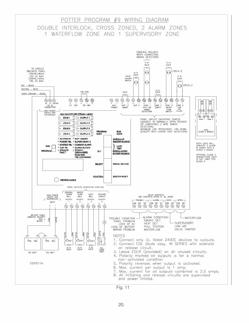
Potter Program #9Double Interlock ProgrammingInstructions(Single Hazard, Cross Zoned, 2Alarm Zones(1 Detection & 1 Low Air), 1Waterflow Zone, and 1 Supervisory Zone)1. Apply power to the panel.2. Slide program switch down.3. Press the FUNCTION button until display reads
"PASSWORD=000."4. To enter a password, press the SELECT button until the
proper number is displayed above the "^" symbol; thenpress the SET button to move to the next digit. Afterentering the third number, the display will change. (Allpanels are shipped with a "000" password).
5. Press the FUNCTION button until the display reads"PROGRAM ##." (the second "#" character refers to thecurrent program number between "0" and "24").
6. Press the SELECT button until the display reads"PROGRAM #9."
7. Press the SET button.8. The panel is completely programmed except for the
custom banner and zone messages. Slide theprogram switch back up.
POTTER PROGRAM #9
ZONES
OUTPUTS *Supervisory 2#1
Conventional
#2Low Air
Supervisory(Empty)
#3Waterflow
#4Low Air Alarm
#1 ALARM X
#2 WATERFLOW X
#3 SUPERVISORY X X X
#4 RELEASE X X
Refer to the "Installation, Operation and Instruction Manual" for the PFC-4410-RCReleasing Control Panel for Additional Information.
INPUTS: 1 supervisory zone, 1 conventional detection zone, 1 low air supervisory zone, 1 waterflow zone, 1 low airalarm zone.
OUTPUTS: 1 general alarm, 1 supervisory, 1 waterflow, 1 solenoid release circuit.OPERATION: Activation of the conventional detection zone and the low air alarm zone at the same time will operate the
solenoid release circuit and the general alarm bell.Activation of the conventional zone only will operate the general alarm output.Activation of the low air supervisory zone will operate the supervisory bell output.Activation of the waterflow zone will operate the waterflow bell output.Activation of the low air alarm zone will operate the supervisory bell output. It will not operate the alarm relay.When Zone #1 is in alarm, Output #1 will operate.When Zone #2 is activated, Output #3 will operate.When Zone #3 is in alarm, Output #2 will operate.When Zone #4 is activated, Output #3 will operate. This will create a supervisory condition not an alarmcondition. The alarm relay will not operate, the supervisory relay will.When both Zones #1 and #4 are activated at the same time, the solenoid circuit will operate.
* The Butterfly valve in the PrePaK assembly is connected to Supervisory 2 input of the Potter PFC-4410RCReleasing/Control panel.
19.
20.
Fig. 11

21.
OUTPUTS
ZONES
*Supervisory 2#1
Conventional#2
Conventional#3
Waterflow#4
Low Air Alarm#1 ALARM X X
#2 WATERFLOW X
#3 SUPERVISORY X X
#4 RELEASE X X X
POTTER PROGRAM #10
Refer to the "Installation, Operation and Instruction Manual" for the PFC-4410-RCReleasing Control Panel for Additional Information.
Potter Program #10Double Interlock Programming Instructions(Single Hazard, Cross Zoned, 3 AlarmZones (2 Detection & 1 Low Air),1 Waterflow Zone, and 1 Supervisory Zone)1. Apply power to the panel.2. Slide program switch down.3. Press the FUNCTION button until the display reads
“PASSWORD=000.”4. To enter a password, press the SELECT button until the
proper number is displayed above the “^” symbol, thenpress the SET button to move to the next digit. Afterentering the third number the display will change. (Allpanels are shipped with a “000” password).
5. Press the FUNCTION button until the display reads“PROGRAM ##.” (the second “#” character refers to thecurrent program number between “0” and “24”).
6. Press the SELECT button until the display reads“PROGRAM #10.”
7. Press the SET button.8. The panel is completely programmed except for the
custom banner and zone messages. Slide the programswitch back up.
INPUTS: 1 supervisory zone, 2 conventional detection zones, 1 waterflow zone, and 1 low air alarm zone.OUTPUTS: 1 general alarm, 1 supervisory,1 waterflow, and 1 solenoid release circuit.OPERATION: Activation of both conventional zones and the low air alarm zone at the same time will operate
the solenoid release circuit and the general alarm bell.Activation of either conventional zone only will operate the general alarm output.Activation of the waterflow zone will operate the waterflow bell output.Activation of the low air alarm zone will operate the supervisory bell output. It will notoperate the alarm relay.When either Zone #1 or #2 is in alarm, Output #1 will operate.When Zone #3 is in alarm, Output #2 will operate.When Zone #4 is activated, Output #3 will operate. This will create a supervisorycondition not an alarm condition. The alarm relay will not operate, the supervisory relay will.When Zones #1, #2 and #4 are activated at the same time, the solenoid release circuit will operate.
* The Butterfly valve in the PrePaK assembly is connected to Supervisory 2 input of the Potter PFC-4410RCReleasing/Control panel.

22.
Fig. 12

23.
CUSTOM PROGRAM #1
ZONES
OUTPUTS *Supervisory 2#1
Conventional#2
Manual Release#3
Waterflow
#4Low Air
Supervisory#1 Alarm X X X
#2 Trouble
#3 Supervisory X X
#4 Release X X
1 conventional zone, 1 manual release zone, 1 waterflow zone, 1 low air zone, 1 supervisory zone.1 general alarm bell, 1 trouble bell, 1 supervisory bell, and 1 solenoid release circuit.Activation of either the conventional zone or the manual release will operate the solenoid releasecircuit and the general alarm bell.Activation of the waterflow zone will operate the general alarm bell.Activation of either the low air zone or the supervisory zone will operate the supervisory bell.A trouble condition (low battery, wiring problem, etc.) will operate the trouble bell.When either Zone #1 or #2 is in alarm, Output #1 (general alarm) and Output #4 (solenoid release)will operate.When Zone #3 is in alarm, Output #1 (alarm bell) will operate.When either Zone #4 or the supervisory zone is activated, Output #3 (supervisory bell) will operate.When the panel is in a trouble condition, Output # 2 (trouble bell) will operate.
INPUTS:OUTPUTS:OPERATION:
Refer to the "Installation, Operation and Instruction Manual" for the PFC-4410-RCReleasing Control Panel for Additional Information.
Custom Program #1(For New York City Compliance)Single Interlock Programming Instructions forNew York City Compliance (Single Hazard, 2Alarm Zones, 1 Waterflow Zone, and 2Supervisory Zones)1. Apply power to the panel.2. Slide the program switch down.3. Press the FUNCTION button until the display reads
“PASSWORD=000.”4. To enter a password, press the SELECT button until the
proper number is displayed above the “^” symbol;then press the SET button to move to the next digit.After entering the third number, the display will change.(All panels are shipped with a “000” password.)
5. Press the FUNCTION button until the display reads“PROGRAM ##.” (the second "#" character refers to thecurrent program number between "0" and "24").
6. Press the SELECT button until the display reads“PROGRAM #6.”
7. Press the SET button.8. Slide the program switch UP.9. Slide the program switch DOWN.10. Apply steps 3 to 5.11. Press the SELECT button until the display reads
“PROGRAM #0.”
12. Press the SET button.13. Press the FUNCTION button until the display reads
“OUTPUT 1: INDICATING.”14. Press the SET button until the display reads “OUTPUT
#2: INDICATING.”15. Press the SELECT button until the display reads
“TROUBLE BELL.” Press the SET button.16. Press the FUNCTION button until the display reads
“ZONE 1 OUTPUTS.” The “v” is pointing to the firstavailable output for the zone indicated on the display. Ifthe number is displayed, it is turned on for that zone. Ifthe number is not displayed, the zone is turned off.
17. Press the FUNCTION button until the display reads“ZONE 3 OUTPUTS.”
18. Press the SELECT button. The “1” should appear underthe “v”.
19. Press the SET button twice. The panel is completelyprogramed except for the custom banner and zonemessages. If these messages are not desired, thenslide the program switch back up.
*The Butterfly valve in the PrePaK assembly is connected to Supervisory 2 input of the Potter PFC-4410RCReleasing/Control panel.

24.
Fig. 13

46
4 = PrePaK Assemblywith 4" (100 mm)
Grooved Ends ModelDDX Deluge Valve
6 = PrePaK Assemblywith 6" (150 mm)
Grooved Ends ModelDDX Deluge Valve
Unit Size
175250
175 = 175 psi(12,1 bar) SystemPressure Rating
250 = 250 psi(17,2 bar) SystemPressure Rating
PressureRating
12
1 = cULus / FMApproved Pressures
Switches
2 = ULC ApprovedPressures Switches
Pressure SwitchApprovals
01234
0 = No Air Compressor1 = ¾ Hp (120 VAC @
60 Hz)Air Compressor
2 = ¾ Hp (220 VAC @50 Hz)
Air Compressor
3 = 1-1/2 Hp (120 VAC@ 60 Hz)
Air Compressor (NotAvailable in the
4" (100 mm) Assembly)
Air CompressorSize
& AC Voltage
Ordering Information:
Model DDX 4" (100mm) & 6" (150mm) PrePAK Part Number Code Key
Example: 4 - 175 - 1 - 1 - 1
4" (100 mm) Model DDX PrePaK Assembly with 175 psi (12,1 bar) System Pressure Rating, cULus / FM ApprovedPressure Switches, ¾ Hp Air Compressor Factory Wired to 120 VAC @ 60 Hz, and Potter PFC-4410-RCReleasing/Control Panel.
01
0 = NoReleasing/Control Panel
1 = PotterPFC-4410-RC
Releasing/Control Panel
Releasing/ControlPanel
25.

SOLENOID VALVE INSPECTIONS, TESTS AND MAINTENANCE
WARNING: THE OWNER IS RESPONSIBLE FOR MAINTAINING THE FIRE PROTECTION SYSTEM IN PROPEROPERATING CONDITION. ANY SYSTEM MAINTENANCE OR TESTING THAT INVOLVES PLACING A CONTROLVALVE OR DETECTION SYSTEM OUT OT SERVICE MAY ELIMINATE THE FIRE PROTECTION OF THAT SYSTEM.PRIOR TO PROCEEDING, NOTIFY ALL AUTHORITIES HAVING JURISDICTION. CONSIDERATION SHOULD BEGIVEN TO EMPLOYMENT OF A FIRE PATROL IN THE AFFECTED AREA.
WARNING: PRIOR TO OPERATING THE SOLENOID VALVE, BE SURE TO CLOSE THE SYSTEMCONTROL VALVE TO AVOID UNINTENTIONAL OPERATION OF THE DELUGE VALVE
1. Inspections: It is imperative that the system be inspected and tested in accordance with NFPA 25 on a regular basis.The frequency of the inspections may vary due to contaminated water supplies, corrosive water supplies, or corrosiveatmospheres. In addition, the alarm devices, detection systems, or other connected trim may require a more frequentschedule. Refer to the system description and applicable codes for minimum requirements.
2. The valve must be operated at least monthly. The valve must open and close freely. When open, the water flow mustbe clear and clean at the proper flow rate. When closed, a total water shut-off must be observed.
3. The valve must be inspected at least monthly for cracks, corrosion, leakage, etc., and cleaned, repaired, or replaced,or replaced as necessary.
4. At least annually, the valve diaphragms and seats must be inspected and if necessary, repaired or replaced.
WARNING: CLOSE SYSTEM CONTROL VALVE, TURN OFF POWER SUPPLY, AND DEPRESSURIZE VALVEBEFORE DISASSEMBLING VALVE. IT IS NOT NECESSARY TO REMOVE THE VALVE FROM THE PIPE LINE TOMAKE INSPECTIONS.
5. When lubricating valve components, use high grade silicone grease (Dow Corning® 111 Compound Lubricant orequal).
6. When reassembling, tighten parts to torque values indicated in the manufacturer’s maintenance instructions (packedwith valve).
7. After maintenance is completed, operate the valve a few times to be sure of proper operation. A metallic “click”signifies the solenoid is operating.
8. It is recommended that the valve be replace at seven-year intervals. Shorter intervals may be required if the valve issubject to corrosive water supplies or atmospheres.
9. All service must be performed by qualified personnel. Upon completion of inspections or replacement of the valve,the entire system must be checked for proper operation. See appropriate system description and testing instructionsfor additional information.
The equipment presented in this bulletin is to be installed in accordance with the latest pertinent Standards of the National Fire Protection Association, FactoryMutual Research Corporation, or other similar organizations and also with the provisions of governmental codes or ordinances whenever applicable.Products manufactured and distributed by Reliable have been protecting life and property for over 80 years, and are installed and serviced by the most highlyqualified and reputable sprinkler contractors located throughout the United States, Canada and foreign countries.
The Reliable Automatic Sprinkler Co., Inc.(800)431–1588 Sales Offices(800)848–6051 Sales Fax(914)829-2042 Corporate Offices
www.reliablesprinkler.com Internet AddressRevision lines indicate updated or new dataE.G. Printed in U.S.A. 06/08 P/N9999970306
Manufactured by
Recycled
Paper