bandwidth improvement of a compact qua- …jpier.org/pierc/pierc41/10.13051705.pdf · drature...
TRANSCRIPT
Progress In Electromagnetics Research C, Vol. 41, 121–135, 2013
BANDWIDTH IMPROVEMENT OF A COMPACT QUA-DRATURE HYBRID COUPLER WITH HARMONICREJECTION USING LUMPED ELEMENTS
Yu Ye1, 2, *, Ling-Yun Li1, Jian-Zhong Gu1,and Xiao-Wei Sun1
1Key Laboratory of Terahertz Solid-State Technology, Shanghai Insti-tute of Microsystem and Information Technology, Shanghai 200050,China
2University of Chinese Academy of Sciences, Beijing 100049, China
Abstract—A compact quadrature hybrid coupler with harmonicsuppression using lumped-element band-stop resonator is proposedfor bandwidth improvement. Conventionally, harmonic rejection isrealized by three band-stop resonators in lumped hybrids. The using ofthree band-stop resonators realizes better harmonic suppression whileexhibiting narrower frequency response. So as to improve operationbandwidth behavior, the number of band-stop resonator applied in theproposed topology is minimized to one. Trading off with acceptablereduction in harmonic rejection, the proposed hybrid enlarges workingbandwidth with fewer numbers of lumped devices. Detailed designand theoretical analysis are presented and the expressions of lumpedelements with dependence of rejected frequency are obtained. Tovalidate the analysis, three 2.45GHz couplers are fabricated on anFR-4 printed circuit board. The experimental results exhibit 27.3%,26.9% and 23.3% operation bandwidth with better than 16 dB, 17 dB,and 21 dB harmonic suppressions at 4.9GHz, 6.1 GHz, and 7.35 GHz,respectively. Less than 0.8 dB amplitude imbalance and 2◦ phase errorare achieved for all the three couplers, which are matched well withtheoretical analysis.
Received 17 May 2013, Accepted 22 June 2013, Scheduled 27 June 2013* Corresponding author: Yu Ye ([email protected]).

122 Ye et al.
1. INTRODUCTION
Hybrid 90◦ couplers are key components to divide or combine signalswith a proper phase difference which are widely implemented inradio frequency (RF) devices, such as power amplifiers, mixers, andantenna systems [1–4]. As couplers are generally designed basedon the electrical length of a desired fundamental signal, higherorder harmonic signals from those nonlinear devices will degradethe quantity of the desired signal. To suppress those unwantedharmonic signals, external low-pass filters are needed [5, 6]. However,such filters increase circuit size and insertion loss. Besides, as RFwireless systems evolve, independently developed standards, such aslong-term evolution (LTE), wireless local area network (WLAN) andmobile world wide interoperability for microwave access (m-WiMAX),increase the number of frequency bands and spectrum fragmentation.Hence, quadrature hybrid couplers for such systems need multimodemultiband (MMMB) capability to cover a number of functions, whichdemands couplers of broader operation frequency range.
Recently, several design techniques have been reported for sizereduction and harmonic suppression, such as rat-race couplers withdefected ground structure (DGS) and micro-strip resonant cells [7–11]and branch-line couplers using slow-wave structure [12–14]. Wirelesscommunication systems usually require smaller device size in order tomeet circuit miniaturization and cost reduction. In lower RF range,although reduction techniques such as multilayer architecture havebeen utilized, couplers mentioned above still remain too large. Besides,couplers with such complicated structures encounter assemblingproblems. For instance, couplers with DGS need backside groundapertures that result in unwanted backside radiation [9].
Therefore, in terms of application where circuit size reduction isrequired, lumped-element devices occupy merely small area is highlyattractive. Over the past years, several lumped-element couplershave been reported [15–18]. However, their interests are mainlyconcentrated on the size reduction. Recently, a lumped-elementcoupler using band-stop resonators to realize harmonic suppressionhas been reported [19], where three band-stop resonators are used.However, due to introducing of three band-stop resonators, thebandwidth is narrowed. Besides, when the rejection frequency is closerto the operation frequency, the bandwidth would degrade.
In this work, a novel 90◦ hybrid coupler with low-pass andhigh-pass lumped-elements supporting MMMB for m-WiMAX (IEEE802.16e)/WLAN (IEEE 802.11b/g/n) is proposed. Comparedwith [19], the only adoption of center band-stop resonator improves

Progress In Electromagnetics Research C, Vol. 41, 2013 123
bandwidth behavior while maintaining good harmonic rejection. Theabout 25% bandwidth supports different bands such as 2.3 GHz(IEEE 802.16e), 2.4 GHz (IEEE 802.11b/g/n), and 2.5–2.7 GHz (IEEE802.16e). Section 2 gives the theoretical analysis of the coupler basedon even- and odd-mode theory. Section 3 describes the experimentalresults. Conclusions are drawn in Section 4.
2. ARCHITECTURE ANALYSIS
The proposed quadrature coupler with harmonic suppression is shownin Fig. 1. The adoption of band-stop resonator (composed by Lr
and Cr) at the center of the topology is for harmonic suppression.Unlike [19], in this topology the number of band-stop resonator isreduced to one to improve working bandwidth. Besides, the numberof devices employed in this topology is decreased for size and costreduction. Overall topology of the proposed hybrid is symmetrical tothe vertical center plane. The even-odd decomposition method [20] is
Figure 1. The topology of proposed quadrature hybrid with harmonicsuppression using center band-stop resonator.
(a) (b)
Figure 2. Even- and odd-mode equivalent half circuits of the topologyin Fig. 1. (a) Odd mode, (b) even mode.
124 Ye et al.
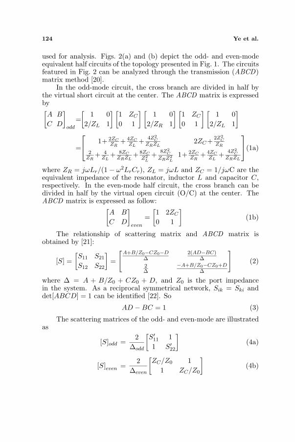
used for analysis. Figs. 2(a) and (b) depict the odd- and even-modeequivalent half circuits of the topology presented in Fig. 1. The circuitsfeatured in Fig. 2 can be analyzed through the transmission (ABCD)matrix method [20].
In the odd-mode circuit, the cross branch are divided in half bythe virtual short circuit at the center. The ABCD matrix is expressedby[A B
C D
]
odd
=[
1 02/ZL 1
] [1 ZC
0 1
] [1 0
2/ZR 1
] [1 ZC
0 1
] [1 0
2/ZL 1
]
=
1+ 2ZC
ZR+ 4ZC
ZL+ 4Z2
CZRZL
2ZC + 2Z2C
ZR
2ZR
+ 4ZL
+ 8ZCZRZL
+ 8ZC
Z2L
+ 8Z2C
ZRZ2L
1+ 2ZCZR
+ 4ZCZL
+ 4Z2C
ZRZL
(1a)
where ZR = jωLr/(1− ω2LrCr), ZL = jωL and ZC = 1/jωC are theequivalent impedance of the resonator, inductor L and capacitor C,respectively. In the even-mode half circuit, the cross branch can bedivided in half by the virtual open circuit (O/C) at the center. TheABCD matrix is expressed as follow:
[A B
C D
]
even
=[1 2ZC
0 1
](1b)
The relationship of scattering matrix and ABCD matrix isobtained by [21]:
[S] =[S11 S21
S12 S22
]=
[A+B/Z0−CZ0−D
∆2(AD−BC)
∆
2∆
−A+B/Z0−CZ0+D∆
](2)
where ∆ = A + B/Z0 + CZ0 + D, and Z0 is the port impedancein the system. As a reciprocal symmetrical network, Sik = Ski anddet[ABCD] = 1 can be identified [22]. So
AD −BC = 1 (3)
The scattering matrices of the odd- and even-mode are illustratedas
[S]odd =2
∆odd
[S′11 11 S′22
](4a)
[S]even =2
∆even
[ZC/Z0 1
1 ZC/Z0
](4b)

Progress In Electromagnetics Research C, Vol. 41, 2013 125
where S′11, S′22, ∆odd and ∆even are written as:
S′11 = S′22 =ZC
Z0+
Z2C
ZRZ0− Z0
ZR− 2Z0
ZL− 4ZCZ0
ZRZL− 4ZCZ0
Z2L
− 4Z2CZ0
ZRZ2L
(5a)
∆odd = 2 +2ZC
Z0+4
(ZC
ZR+
2ZC
ZL+
2Z2C
ZRZL
)+2
(Z2
C
Z0ZR+
2Z0
ZL
+Z0
ZR+
4Z0ZC
ZRZL+
4Z0ZC
Z2L
+4Z0Z
2C
ZRZ2L
)(5b)
∆even = 2 +2ZC
Z0(5c)
The scattering parameters (S-parameters) of the hybrid are givenby
S11 =12
(Se11 + So
11) (6a)
S21 =12
(Se11 − So
11) (6b)
S31 =12
(Se21 − So
21) (6c)
S41 =12
(Se21 + So
21) (6d)
At the operation frequency ω0, with (3), the following equation isobtained:
4(
ZC
ZR
)(ZC
ZR+ 1
)(2ZC
ZL+ 1
) (2ZR
ZL+
2ZC
ZL+ 1
)= 0 (7)
To satisfy (7), the ratio of (ZC/ZR) equals to −1, which is a uniquesolution at the frequency ω0. Besides, if the band-stop resonator’sresonant frequency is defined to be ωr, the relationship between ωr
and ω0 can be obtained as ω2r = 1/LrCr = (kω0)2, where k is the ratio
of (ωr/ω0). When the conditions of L = Z0/ω0 and C = 1/(ω0Z0) areset [15], S11 = S41 = 0 is proven at the frequency ω0. L, Lr, C, andCr are:
L =Z0
ω0(8a)
Lr =(
1− 1k2
)Z0
ω0(8b)
C =1
ω0Z0(8c)
Cr =1
(k2 − 1)ω0Z0(8d)

126 Ye et al.
Thus, the Equations 6(b) and (c) are
S21 =12
(1− j) (9a)
S31 =12
(1 + j) (9b)
From the above expressions, it is evident that at the centerfrequency ω0 the hybrid is matched and has perfect isolation. Thepower that exited at port 1 is delivered identically to ports 2 and 3with a quadrature phase difference. The theoretical hybrid scatteringmatrix at the frequency ω0 is obtained by
[S]coupler =12
0 1− j 1 + j 01− j 0 0 1 + j1 + j 0 0 1− j
0 1 + j 1− j 0
(10)
The relationship of unwanted harmonic frequency and ω0 can bedefined as ωh = nω0, where ωh is the unwanted harmonic frequencyand n the rejected harmonic index. For perfect power rejection atfrequency nω0, the transmission coefficients from port 1 to ports 2 and3 need to be zero, which is written as follow
S21 = S31 = 0 (11)Substitute S21 and S31 by (6b) and (6c), ∆odd = ∆even is derived
at frequency nω0 to satisfy (11). Then the following equation is derivedas
4(
ZC
ZR+
2ZC
ZL+
2Z2C
ZRZL
)+ 2
(Z2
C
Z0ZR+
2Z0
ZL+
Z0
ZR
+4Z0ZC
ZRZL+
4Z0ZC
Z2L
+4Z0Z
2C
ZRZ2L
)= 0 (12)
An approximate equation based on (12) can be expressed as
4jk + 8jk
(n2 − 1n2 − k2
)− 8j
1k
= 0 (13)
The solution to (12) is
k2 =n4
3n2 − 2(14)
then Lr and Cr can be written as
Lr =(
1− 3n2 − 2n4
)Z0
ω0(15a)
Cr =1(
n4
3n2−2− 1
)ω0Z0
(15b)

Progress In Electromagnetics Research C, Vol. 41, 2013 127
So the band-stop resonator used in the proposed topology can beselected using (15a) and (15b) to achieve transmission stop at nω0.Thus, S21 and S31 of the coupler at frequency nω0 are given by
S21 = −S31 =12
[j
n− j− jn
(n2 − 2)− jn
](16)
According to (16), the theoretical out-of-band harmonic suppres-sion is plotted in Fig. 3(a). The harmonic rejection performance im-proves when the harmonic index, n, increases. When n is biggerthan 2.3, theoretically the coupler provides over 20 dB harmonic re-jection. Over 30 dB harmonic rejection is achieved when n is big-ger than 3. Theoretical normalized frequency dependence of the S-parameters for the coupler with n = 2, 2.5 and 3, respectively, areshown in Figs. 3(b), (c) and (d). When n = 2, 2.5 and 3, the cou-pler exhibits theoretical operation bandwidth of 25.3% (0.971–1.224),26.5% (0.959–1.224), and 24.9% (0.943–1.192), respectively. Less than4 dB insertion loss (IL) and better than 10 dB, 13 dB and 15 dB re-turn loss are achieved within the operation bandwidth, respectively,for n = 2, 2.5 and 3. The amplitude imbalance (AI) and phase differ-ence (PD) between ports 2 and 3 are illustrated in Figs. 3(e) and (f).Less than 1 dB AI and less than 5◦ PD are achieved with n = 2, 2.5and 3, while the harmonic rejection are better than 16 dB, 22 dB and27 dB, respectively. As shown in Fig. 3, in contrast to [19], the AIand PD of the proposed couplers are improved. Besides, the below−20 dB return loss and isolation of the proposed couplers remain sim-ilar with [19]. However, at the upper side operation band, the per-formance degrades if the rejected harmonic frequency is close to theoperational frequency. As tabulated in Table 1, although not as goodas [19] in rejection behavior, the proposed topology provides wider op-eration bandwidth while with acceptable harmonic rejection. Besides,the fewer number of lumped devices reduce the size and cost.
3. IMPLEMENTATION OF LUMPED-ELEMENTQUADRATURE COUPLER
A low-cost FR-4 printed circuit board with a dielectric constant of 4.5and thickness of 0.8 mm was employed to validate analytical results,where the surface mounted devices (SMD) of the lumped inductorsand capacitors are adopted. Three lumped quadrature couplerswith n = 2, 2.5 and 3 were fabricated. The values of the passivelumped elements L, Lr, C, and Cr are 3.3 nH/1.2 nH/1.3 pF/2.2 pF,3.3 nH/1.9 nH/1.3 pF/1 pF, and 3.3 nH/2.3 nH/1.3 pF/0.6 pF for n =2, 2.5 and 3, respectively. The couplers with harmonic suppression are

128 Ye et al.
(a) (b)
(c) (d)
(e) (f)
Figure 3. Theoretical analysis results in contrast with [19].(a) Harmonic suppression tuned with n. (b) S-parameters when n = 2.(c) S-parameters when n = 2.5. (d) S-parameters when n = 3. (e) AIwith different n (2, 2.5 and 3). (f) PD with different n (2, 2.5 and 3).
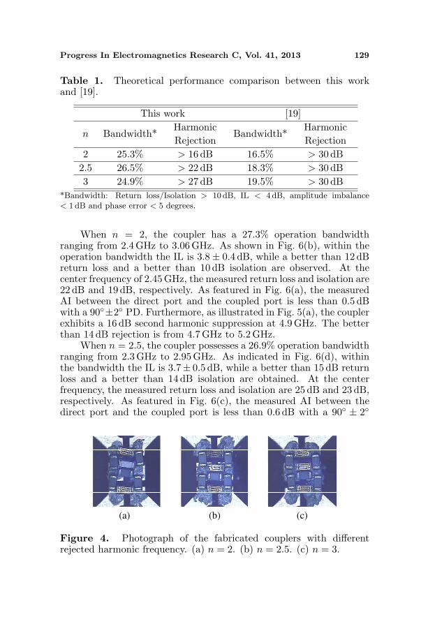
implemented at 2.45 GHz. Photographs of the fabricated circuits arefeatured in Fig. 4. The overall dimension of the core circuit is only2mm × 2.2mm for each hybrid coupler. An Agilent PNA N5245Afour-port network analyzer was used to obtain measurements of thecouplers.
The measured results and theoretical simulated results of S-parameters for n = 2, 2.5 and 3 are demonstrated in Fig. 5, wheremeasured results are in good agreement with theoretical analysis. Themeasured performance of AI and PD between the direct port and thecoupled port are illustrated in Fig. 6 with different harmonic rejection(n = 2, 2.5 and 3). The measured IL with different n are also plottedin Fig. 6.
Progress In Electromagnetics Research C, Vol. 41, 2013 129
Table 1. Theoretical performance comparison between this workand [19].
This work [19]
n Bandwidth*HarmonicRejection
Bandwidth*HarmonicRejection
2 25.3% > 16 dB 16.5% > 30 dB2.5 26.5% > 22 dB 18.3% > 30 dB3 24.9% > 27 dB 19.5% > 30 dB
*Bandwidth: Return loss/Isolation > 10 dB, IL < 4 dB, amplitude imbalance< 1 dB and phase error < 5 degrees.
When n = 2, the coupler has a 27.3% operation bandwidthranging from 2.4GHz to 3.06 GHz. As shown in Fig. 6(b), within theoperation bandwidth the IL is 3.8± 0.4 dB, while a better than 12 dBreturn loss and a better than 10 dB isolation are observed. At thecenter frequency of 2.45GHz, the measured return loss and isolation are22 dB and 19 dB, respectively. As featured in Fig. 6(a), the measuredAI between the direct port and the coupled port is less than 0.5 dBwith a 90◦±2◦ PD. Furthermore, as illustrated in Fig. 5(a), the couplerexhibits a 16 dB second harmonic suppression at 4.9GHz. The betterthan 14 dB rejection is from 4.7 GHz to 5.2GHz.
When n = 2.5, the coupler possesses a 26.9% operation bandwidthranging from 2.3 GHz to 2.95 GHz. As indicated in Fig. 6(d), withinthe bandwidth the IL is 3.7± 0.5 dB, while a better than 15 dB returnloss and a better than 14 dB isolation are obtained. At the centerfrequency, the measured return loss and isolation are 25 dB and 23 dB,respectively. As featured in Fig. 6(c), the measured AI between thedirect port and the coupled port is less than 0.6 dB with a 90◦ ± 2◦
(a) (b) (c)
Figure 4. Photograph of the fabricated couplers with differentrejected harmonic frequency. (a) n = 2. (b) n = 2.5. (c) n = 3.

130 Ye et al.
PD. Besides, as illustrated in Fig. 5(b), the coupler exhibit 16 dB and17 dB harmonic suppression in the direct port and the coupled port at6.1GHz, respectively. The better than 15 dB rejection is from 5.3 GHzto 6.3 GHz.
When n = 3, the coupler exhibits a 24.1% operation bandwidthfrom 2.28 GHz to 2.86GHz. As featured in Fig. 6(f), the IL is3.7 ± 0.4 dB, while a better than 15 dB return loss and a better than14 dB isolation are achieved. The measured return loss and isolationare 29 dB and 22 dB at 2.45 GHz, respectively. The measured AIbetween the direct port and the coupled port is less than 0.8 dB witha 90◦ ± 2◦ PD, which are featured in Fig. 6(e). Furthermore, asillustrated in Fig. 5(c), the coupler exhibits 30 dB and 21 dB thirdharmonic suppressions in the direct port and the coupled port at7.3GHz, respectively. The better than 15 dB rejection is from 6.3 GHzto 8.4 GHz.
These measured results illustrate that the proposed couplerachieves good operation performance with sufficient out-band rejection.Furthermore, the measured results validate the analytical solutionsin a good agreement. However, IL degrades when compared to thetheoretical analysis, which may because of the parasitic effects andcomponent diversions of the SMDs. For better understanding, a±5% tolerance in each component is included, which is reasonablein common SMDs. The statistical simulated results of S21 and S31
(a) (b)
(c)
Figure 5. Measured and theoretical simulated results of S-parameterswith different n. (a) n = 2. (b) n = 2.5. (c) n = 3.

Progress In Electromagnetics Research C, Vol. 41, 2013 131
(a) (b)
(c) (d)
(e) (f)
Figure 6. Measured and theoretical simulated results of the AI, PDand IL with different n. (a) AI and PD (n = 2). (b) IL (n = 2). (c) AIand PD (n = 2.5). (d) IL (n = 2.5). (e) AI and PD (n = 3). (f) IL(n = 3).
Figure 7. Statistical simulation results of the proposed coupler withn = 3, where a ±5% tolerance is included in each component and itsparasitic resistance.

132 Ye et al.
Table 2. Performance comparison between this work and publishedwork.
ReferenceFrequency
(f0)Bandwidth
Harmonic
RejectionSize (mm2) Tech.
[7] 2GHz 5%> 30 dB
(2f0 − 4f0)13.89× 17.62 Rat-race
[8] 2.45GHz 20.4%> 20 dB
(3f0 − 5f0)306.35 Rat-race
[11] 900MHz 13%> 20 dB
(2f0)18× 34.5 Rat-race
[12] 2 GHz 10%> 22.5 dB
(2f0)265.69 Branch-line
[13] 836.5MHz 6%> 18 dB
(2f0)27.75× 25.7 Branch-line
[14] 1 GHz 16%> 20 dB
(4f0 − 6f0)30.2× 31.7 Branch-line
[19] 2.45GHz 16.3%> 25 dB
(2f0)2× 2.5 SMD
This
Work*2.45GHz 27.3%
> 16 dB
(2f0)2× 2.2 SMD
This
Work*2.45GHz 26.9%
> 17 dB
(2.5f0)2× 2.2 SMD
This
Work*2.45GHz 24.1%
> 20 dB
(3f0)2× 2.2 SMD
*Bandwidth: Return loss/Isolation > 10 dB, IL < 4 dB, AI < 0.8 dB and phaseerror < 2 degrees.
are illustrated in Fig. 7, which shows approximate ±0.3 dB variationsin S21 and S31 around the operation frequency. Considering thesestatistical variations, the measured results are within an acceptablevariation range. It features a reasonable deviation between theoreticaland measured results. Table 2 tabulates the comparisons betweenthis work and previous published reports. As listed in Table 2, incontrast with rat-race or branch-line couplers, this compact topologyprovides harmonic rejection with significant size and cost reduction.What’s more, with similar in-band performance such as IL, returnloss, and PD, compared to previous reports, this topology exhibitswider operation frequency range.

Progress In Electromagnetics Research C, Vol. 41, 2013 133
4. CONCLUSION
A compact quadrature hybrid coupler with harmonic suppression usinglumped-element band-stop resonator is presented. In order to improvethe operation bandwidth while with sufficient harmonic rejection, inthe proposed topology the number of band-stop resonator is minimizedto one. Besides, compared to rat-race or branch-line couplers, thistopology provides harmonic rejection with significant size and costreduction. Detailed design and theoretical analysis are presented forthe proposed coupler and the expressions of lumped elements areobtained. Promising agreements between experimental results andtheoretical analysis are achieved. In contrast to other lumped-elementcouplers with harmonic rejection, the proposed topology exhibits wideroperation frequency which can be applied in MMMB system for m-WiMAX (IEEE 802.16e)/WLAN (IEEE 802.11b/g/n).
ACKNOWLEDGMENT
This work is supported by National Science and Technology MajorProject (No. 2011ZX0300400202).
REFERENCES
1. Ozis, D., J. Paramesh, and D. J. Allstot, “Integrated quadraturecouplers and their application in image-reject receivers,” IEEE J.Solid-State Circuits., Vol. 44, No. 5, 1464–1476, May 2009.
2. Chang, C.-W., Y.-J. E. Chen, and J.-H. Chen, “A power-recycling technique for improving power amplifier efficiency underload mismatch,” IEEE Microw. Wireless Compon. Lett., Vol. 21,No. 10, 571–573, Oct. 2011.
3. Bulus, U., O. Kizilbey, H. Aniktar, and A. Gunes, “Broadbanddirection-finding antenna using suspended microstrip-line hybridcoupler for handheld devices,” IEEE Antennas Wireless Propag.Lett., Vol. 12, 80–83, 2013.
4. Shu, P. and Q. Feng, “Design of a compact quad-band hybridantenna for compass/WiMAX/MLAN applications,” Progress InElectromagnetics Research, Vol. 138, 585–598, 2013.
5. Wong, Y. S., S. Y. Zheng, and W. S. Chan, “Multifoldedbandwidth branch line coupler with filtering characteristic usingcoupled port feeding,” Progress In Electromagnetics Research,Vol. 118, 17–35, 2011.

134 Ye et al.
6. Cheng, Y. J., L. Wang, J. Wu, and Y. Fan, “Directional couplerwith good restraint outside the passband and its frequency-agileapplication,” Progress In Electromagnetics Research, Vol. 135,759–771, 2013.
7. Wang, W.-H., T.-M. Huang, and R.-B. Wu, “Miniatured rat-racecoupler with bandpass response and good stopband rejection,”IEEE MTT-S Int. Microwave Symp. Dig., 709–712, 2009.
8. Kuo, J.-T., J.-S. Wu, and Y.-C. Chiou, “Miniaturized rat racecoupler with suppression of spurious passband,” IEEE Microw.Wireless Compon. Lett., Vol. 17, No. 1, 46–48, Aug. 2007.
9. Sung, Y. J., C. S. Ahn, and Y.-S. Kim, “Size reductionand harmonic suppression of rat-race hybrid coupler usingdefected ground structure,” IEEE Microw. Wireless Compon.Lett., Vol. 14, No. 1, 7–9, Jan. 2004.
10. Gu, J.-Z. and X.-W. Sun, “Miniaturization and harmonicsuppression rat-race coupler using C-SCMRC resonators withdistributive equivalent circuit,” IEEE Microw. Wireless Compon.Lett., Vol. 15, No. 12, 880–882, Dec. 2005.
11. Chiu, H.-C., C.-H. Lai, and T.-G. Ma, “Miniaturized rat-race coupler with out-of-band suppression using double-layersynthesized coplanar waveguides,” IEEE MTT-S Int. MicrowaveSymp. Dig., 2012.
12. Wang, J., B.-Z. Wang, Y.-X. Guo, L. C. Ong, and S. Q. Xiao,“A compact slow-wave microstrip branch-line coupler with highperformance,” IEEE Microw. Wireless Compon. Lett., Vol. 17,No. 7, 501–503, Jul. 2007.
13. Tsai, K.-Y., H.-S. Yang, J.-H. Chen, and Y.-J. E. Chen, “Aminiaturized 3 dB branch-line hybrid coupler with harmonicssuppression,” IEEE Microw. Wireless Compon. Lett., Vol. 21,No. 10, 537–539, Oct. 2011.
14. Hazeri, A. R. and T. Faraji, “Miniaturization and harmonicsuppression of the branch-line hybrid coupler,” Int. J. Electron,Vol. 98, No. 12, 1699–1710, Dec. 2011.
15. Hou, J. A. and Y. H. Wang, “A compact quadrature hybridbased on high-pass and low-pass lumped elements,” IEEE Microw.Wireless Compon. Lett., Vol. 17, No. 8, 595–597, Aug. 2007.
16. Ohta, I., X. P. Li, T. Kawai, and Y. Kokubo, “A design of lumped-element 3 dB quadrature hybrids,” Proc. Asia-Pacific Microw.Conf., Vol. 3, 1141–1144, Dec. 1997.
17. Chiang, Y. C. and C. Y. Chen, “Design of a wideband lumped-element 3-dB quadrature coupler,” IEEE Trans. on Microw.

Progress In Electromagnetics Research C, Vol. 41, 2013 135
Theory and Tech., Vol. 49, No. 3, 476–479, 2001.18. Vogel, R. W., “Analysis and design of lumped and lumped
distributed element directional couplers for MIC and MMICapplications,” IEEE Trans. on Microw. Theory and Tech., Vol. 40,No. 2, 253–262, 1992.
19. Hou, J. A. and Y. H. Wang, “Design of compact 90◦ and180◦ couplers with harmonic suppression using lumped-elementbandstop resonators,” IEEE Trans. on Microw. Theory and Tech.,Vol. 58, No. 11, 2932–2939, Nov. 2010.
20. Reed, J. and G. J. Wheeler, “A method of analysis of symmetricalfour-port networks,” IEEE Trans. on Microw. Theory and Tech.,Vol. 4, No. 4, 246–252, Oct. 1956.
21. Pozar, D. M., Microwave Engineering, Artech House, Norwell,MA, 1990.
22. Faria, J. A., Multiconductor Transmission-line Structures, NewYork, Wiley, 1993.