beam design1
TRANSCRIPT

BEAM DESIGN
SLAB SEC. DESIGN
BEAM CAPACITY
SLAB SEC. CAPACITY
BEAM ANALYSIS & DESIGN
BEAM DSN. ACI COEFF.
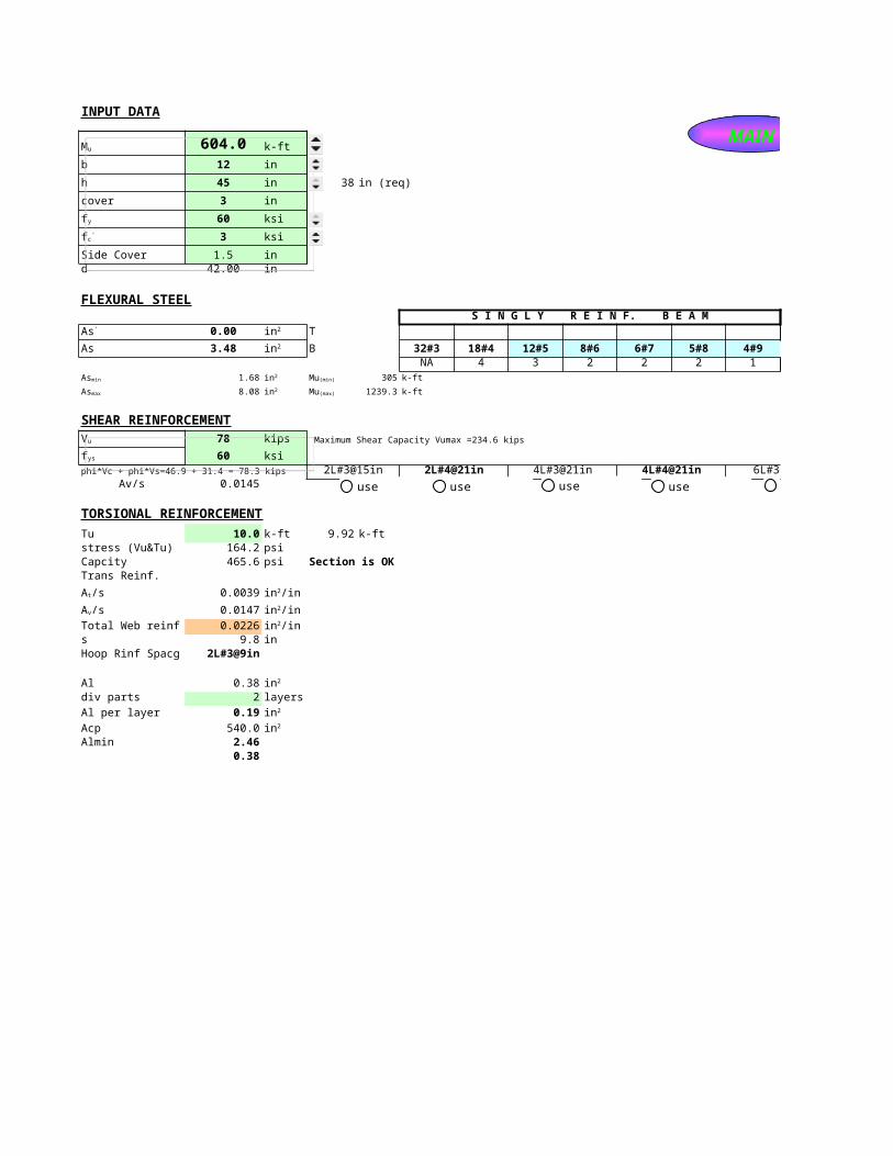
INPUT DATA
604.0 k-ft
b 12 in
h 45 in 38 in (req)
cover 3 in
60 ksi
3 ksi
Side Cover 1.5 ind 42.00 in
FLEXURAL STEELS I N G L Y R E I N F. B E A M
0.00 T 1#3 1#4 1#5 1#6 1#7 1#8 1#9 TOP STEEL
As 3.48 B 32#3 18#4 12#5 8#6 6#7 5#8 4#9 BOTTOM STEELNA 4 3 2 2 2 1 <-- No of Layers (B)
1.68 305 k-ft
8.08 1239.3 k-ft
SHEAR REINFORCEMENT78 kips Maximum Shear Capacity Vumax =234.6 kips
60 ksiphi*Vc + phi*Vs=46.9 + 31.4 = 78.3 kips 2L#3@15in 2L#4@21in 4L#3@21in 4L#4@21in 6L#3@21in
Av/s 0.0145
TORSIONAL REINFORCEMENT
Tu 10.0 k-ft 9.92 k-ftstress (Vu&Tu) 164.2 psiCapcity 465.6 psi Section is OKTrans Reinf.
0.0039
0.0147
Total Web reinf 0.0226s 9.8 in Hoop Rinf Spacg 2L#3@9in
Al 0.38div parts 2 layers
Al per layer 0.19
Acp 540.0Almin 2.46
0.38
Mu
fy
fc'
As' in2
in2
Asmin in2 Mu(min)
Asmax in2 Mu(max)
Vu
fys
At/s in2/in
Av/s in2/in
in2/in
in2
in2
in2
MAIN
use use use use use
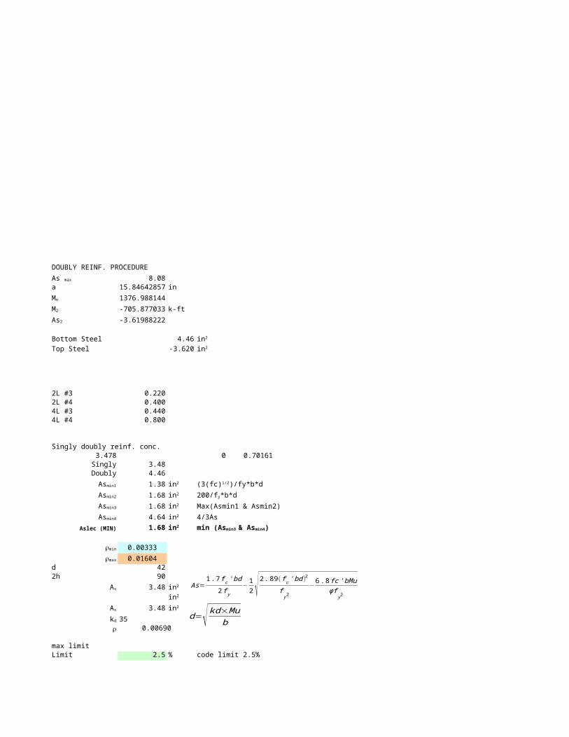
DOUBLY REINF. PROCEDURE
8.08a 15.84642857 in
1376.988144
-705.877033 k-ft
-3.61988222
Bottom Steel 4.46
Top Steel -3.620
2L #3 0.2202L #4 0.4004L #3 0.4404L #4 0.800
Singly doubly reinf. conc.3.478 0 0.70161Singly 3.48
Doubly 4.46
1.38
1.68
1.68 Max(Asmin1 & Asmin2)
4.64 4/3As
Aslec (MIN) 1.68
0.00333
0.01604d 422h 90
3.48
3.48
35r 0.00690
max limitLimit 2.5 % code limit 2.5%
As max
Mn
M2
As2
in2
in2
Asmin1 in2 (3(fc)1/2)/fy*b*d
Asmin2 in2 200/fy*b*d
Asmin3 in2
Asmin4 in2
in2 min (Asmin3 & Asmin4)
rmin
rmax
As in2
in2
As in2
kd
As=1 .7 f c ' bd
2 f y−12 √ 2.89( f c ' bd )2
fy2
−6 .8 fc ' bMuφf
y2
d=√ kd×Mub
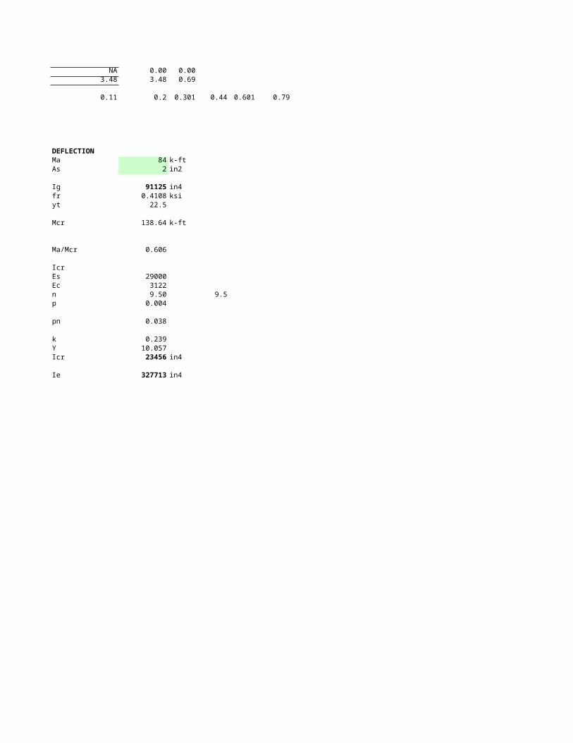
NA 0.00 0.003.48 3.48 0.69
0.11 0.2 0.301 0.44 0.601 0.79
DEFLECTIONMa 84 k-ftAs 2 in2
Ig 91125 in4fr 0.4108 ksiyt 22.5
Mcr 138.64 k-ft
Ma/Mcr 0.606
IcrEs 29000Ec 3122n 9.50 9.5p 0.004
pn 0.038
k 0.239Y 10.057Icr 23456 in4
Ie 327713 in4
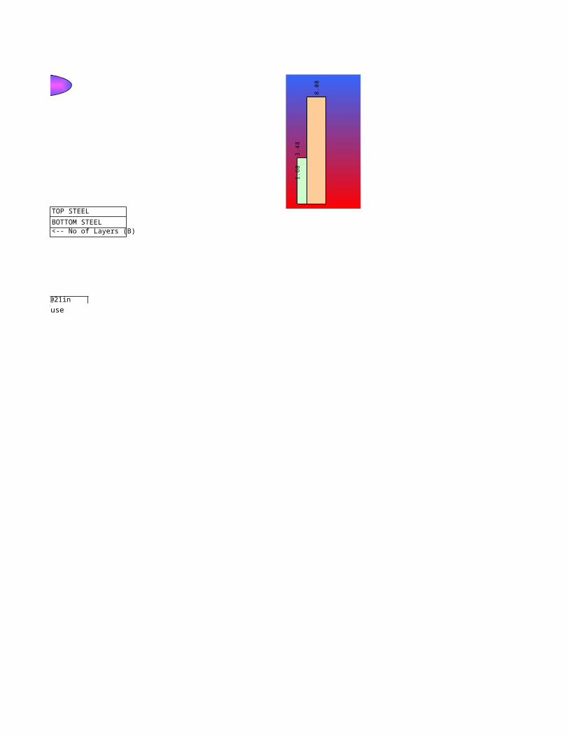
TOP STEEL
BOTTOM STEEL<-- No of Layers (B)
1.6
8
3.4
8
8.0
8
use
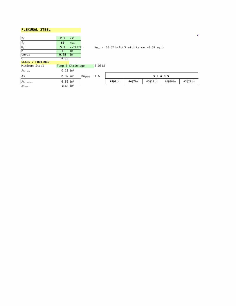
FLEXURAL STEEL
2.5 ksi
60 ksi
5.5 k-ft/ft 10.57 k-ft/ft with As max =0.68 sq.inh 5 incover 0.75 ind 4.25SLABS / FOOTINGSMinimum Steel Temp & Shrinkage 0.0018
0.11
As 0.32 1.6 S L A B S
0.32 #3@4in #4@7in #5@11in #6@16in #7@22in #8@30in <--- spacing in slab
0.68
fc'
fy
Mu Mumax =
As min in2
in2 Mu(min)
As select in2
As max in2
MAIN
<--- spacing in slab
MAIN
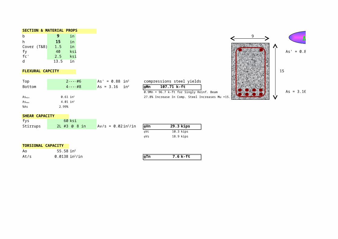
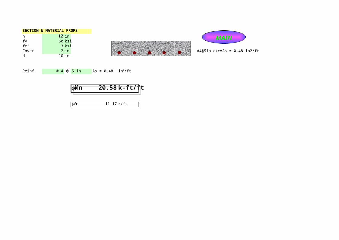
SECTION & MATERIAL PROPS
b 9 in 9
h 15 inCover (T&B) 1.5 infy 40 ksi As' = 0.88fc' 2.5 ksid 13.5 in
FLEXURAL CAPCITY 15
Top 2 ---- #6 As' = 0.88 compressions steel yields
Bottom 4 ---- #8 As = 3.16 107.71 k-ft0.9Mn = 96.7 k-ft for Singly Reinf. Beam As = 3.16
0.61 27.8% Increase In Comp. Steel Increases Mu =15.1%
4.01
%As 2.99%
SHEAR CAPACITYfys 60 ksi
Stirrups 2L #3 @ 8 in Av/s = 0.028 29.3 kips10.3 kips
18.9 kips
TORSIONAL CAPACITY
Ao 55.58
At/s 0.0138 7.6 k-ft
in2
in2 fMn
Asmin in2
Asmax in2
in2/in fVnfVc
fVs
in2
in2/in fTn
MAIN

MAIN
SECTION & MATERIAL PROPS
h 12 infy 60 ksifc' 3 ksiCover 2 in #4@5in c/c=As = 0.48 in2/ftd 10 in
Reinf. # 4 @ 5 in As = 0.48
20.58 k-ft/ft
11.17 k/ft
in2/ft
fMn
fVc
MAIN
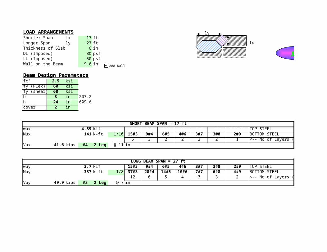
LOAD ARRANGEMENTSShorter Span lx 17 ftLonger Span ly 27 ftThickness of Slab 6 inDL (Imposed) 80 psfLL (Imposed) 50 psfWall on the Beam 9.0 in
Beam Design Parametersfc' 2.5 ksify (Flex) 60 ksify (shear) 60 ksib 8 in 203.2h 24 in 609.6cover 2 in
SHORT BEAM SPAN = 17 ftwux 4.89 klf ### ### ### ### ### ### #VALUE! TOP STEELMux 141 k-ft 1/10 15#3 9#4 6#5 4#6 3#7 3#8 2#9 BOTTOM STEEL 2
5 3 2 2 2 2 1 <-- No of Layers (B)Vux 41.6 kips #4 2 Leg @ 11 in
LONG BEAM SPAN = 27 ftwuy 3.7 klf 15#3 9#4 6#5 4#6 3#7 3#8 2#9 TOP STEELMuy 337 k-ft 1/8 37#3 20#4 14#5 10#6 7#7 6#8 4#9 BOTTOM STEEL 1
12 6 5 4 3 3 2 <-- No of Layers (B)Vuy 49.9 kips #3 2 Leg @ 7 in
ly
lx
MAIN
Add Wall

Panels on short side
Panels on long side
MAIN
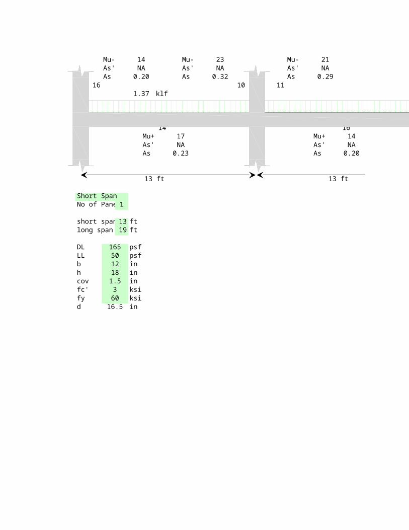
Mu- 14 Mu- 23 Mu- 21As' NA As' NA As' NAAs 0.20 As 0.32 As 0.29
16 10 111.37 klf
14 16Mu+ 17 Mu+ 14As' NA As' NAAs 0.23 As 0.20
13 ft 13 ft
Short SpanNo of Panel 1
short span 13 ftlong span 19 ft
DL 165 psfLL 50 psfb 12 inh 18 incov 1.5 infc' 3 ksify 60 ksid 16.5 in
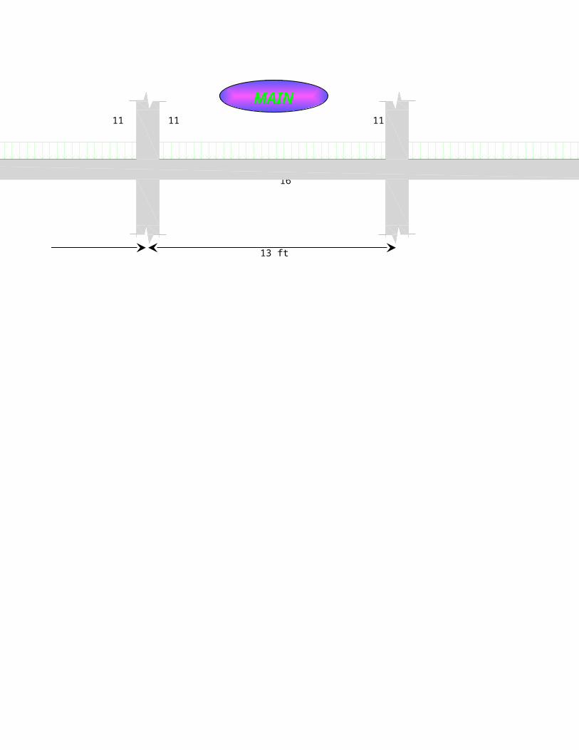
11 11 11
16
13 ft
MAIN

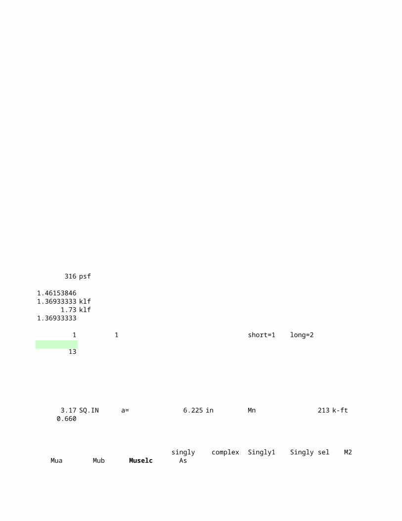
wu 316 psf
k 1.46153846wua 1.36933333 klfwub 1.73 klfwusel 1.36933333
Span selct 1 1
span 13
Asmax 3.17 SQ.INasmin 0.660
Mua Mub

8 29 789 26 70
10 23 6311 21 5714 17 4516 14 39
short=1 long=2
a= 6.225 in Mn 213 k-ft
singly complex Singly1 Singly sel M2 doublyMuselc As As' As
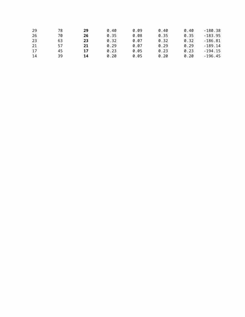
29 0.40 0.09 0.40 0.40 -180.38 -2.4050 0.7726 0.35 0.08 0.35 0.35 -183.95 -2.4527 0.7223 0.32 0.07 0.32 0.32 -186.81 -2.4908 0.6821 0.29 0.07 0.29 0.29 -189.14 -2.5219 0.6517 0.23 0.05 0.23 0.23 -194.15 -2.5887 0.5914 0.20 0.05 0.20 0.20 -196.45 -2.6193 0.56
Top Bot
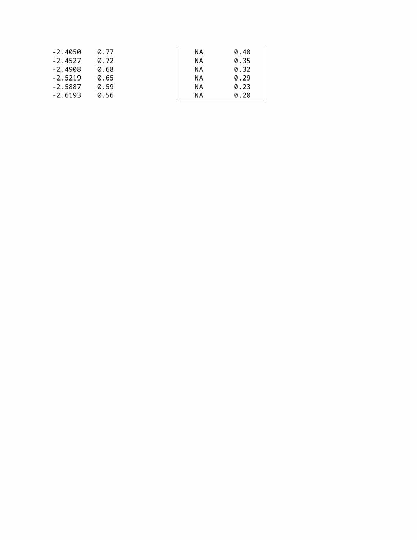
NA 0.40NA 0.35NA 0.32NA 0.29NA 0.23NA 0.20
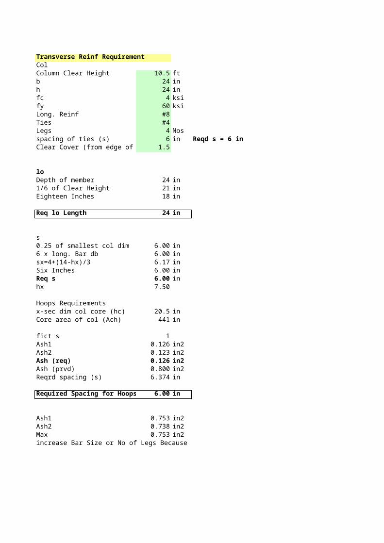
Transverse Reinf RequirementColColumn Clear Height 10.5 ftb 24 inh 24 infc 4 ksify 60 ksiLong. Reinf #8Ties #4Legs 4 Nosspacing of ties (s) 6 in Reqd s = 6 inClear Cover (from edge of tie) 1.5
loDepth of member 24 in1/6 of Clear Height 21 inEighteen Inches 18 in
Req lo Length 24 in
s0.25 of smallest col dim 6.00 in6 x long. Bar db 6.00 insx=4+(14-hx)/3 6.17 inSix Inches 6.00 inReq s 6.00 inhx 7.50
Hoops Requirementsx-sec dim col core (hc) 20.5 inCore area of col (Ach) 441 in
fict s 1Ash1 0.126 in2Ash2 0.123 in2Ash (req) 0.126 in2Ash (prvd) 0.800 in2Reqrd spacing (s) 6.374 in
Required Spacing for Hoops 6.00 in
Ash1 0.753 in2Ash2 0.738 in2Max 0.753 in2increase Bar Size or No of Legs Because
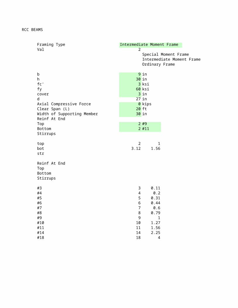
RCC BEAMS
Framing Type Intermediate Moment FrameVal 2
Special Moment Frame 1Intermediate Moment Frame 2Ordinary Frame 3
b 9 inh 30 infc' 3 ksify 60 ksicover 3 ind 27 inAxial Compressive Force 0 kipsClear Span (L) 20 ftWidth of Supporting Member 30 inReinf At EndTop 2 #9Bottom 2 #11 GeneralStirrups
top 2 1bot 3.12 1.56str
Reinf At EndTopBottomStirrups
#3 3 0.11#4 4 0.2#5 5 0.31#6 6 0.44#7 7 0.6#8 8 0.79#9 9 1#10 10 1.27#11 11 1.56#14 14 2.25#18 18 4
Sp Int
Ord
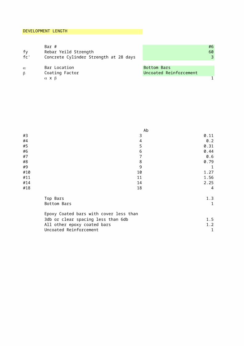
DEVELOPMENT LENGTH
Bar # #6fy Rebar Yeild Strength 60fc' Concrete Cylinder Strength at 28 days 3
a Bar Location Bottom Bars ab Coating Factor Uncoated Reinforcement b
1 < 1.7
Ab db#3 3 0.11#4 4 0.2#5 5 0.31#6 6 0.44#7 7 0.6#8 8 0.79#9 9 1#10 10 1.27#11 11 1.56#14 14 2.25#18 18 4
Top Bars 1.3Bottom Bars 1
1.5All other epoxy coated bars 1.2Uncoated Reinforcement 1
a x b
Epoxy Coated bars with cover less than 3db or clear spacing less than 6db
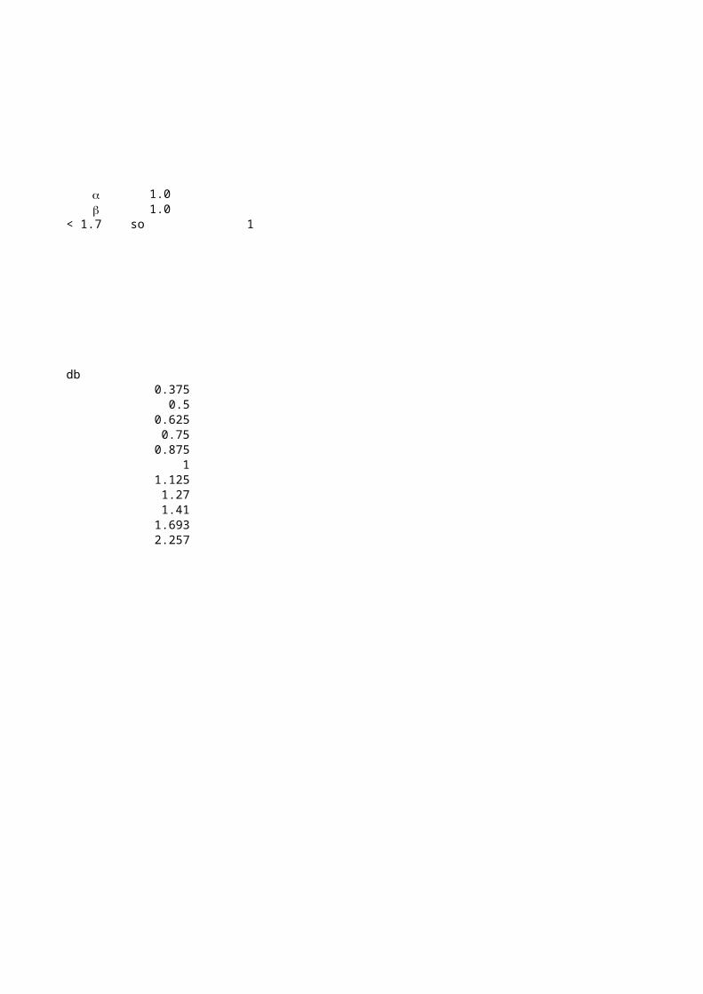
1.01.0
so 1
0.3750.5
0.6250.75
0.8751
1.1251.271.41
1.6932.257
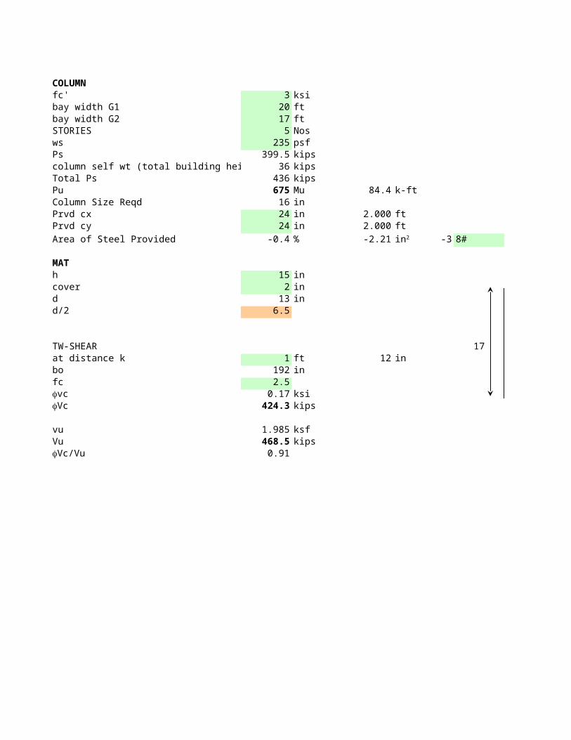
COLUMNfc' 3 ksibay width G1 20 ftbay width G2 17 ftSTORIES 5 Nosws 235 psfPs 399.5 kipscolumn self wt (total building height) 36 kipsTotal Ps 436 kipsPu 675 Mu 84.4 k-ftColumn Size Reqd 16 inPrvd cx 24 in 2.000 ftPrvd cy 24 in 2.000 ft
Area of Steel Provided -0.4 % -2.21 -3 8#
MATh 15 incover 2 ind 13 ind/2 6.5
TW-SHEAR 17at distance k 1 ft 12 inbo 192 infc 2.5
0.17 ksi424.3 kips
vu 1.985 ksfVu 468.5 kips
0.91
in2
fvcfVc
fVc/Vu
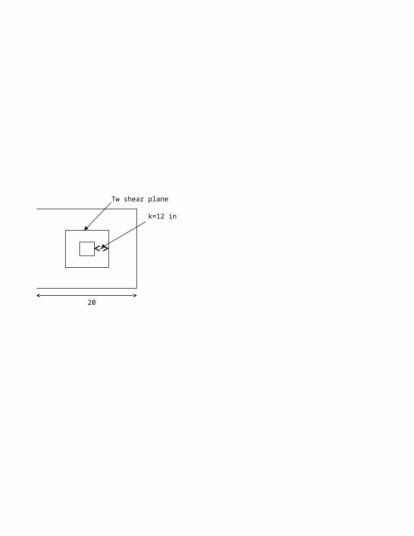
Tw shear plane
k=12 in
20
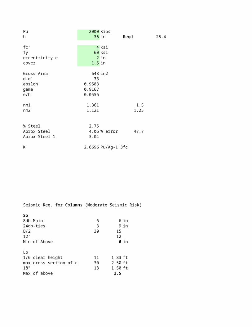
Pu 2000 Kips eh 36 in Reqd 25.4 1
1.2fc' 4 ksi 1.3fy 60 ksi 1.4eccentricity e 2 in 1.5cover 1.5 in 1.6
1.7Gross Area 648 in2 1.8d-d' 33 1.9epslon 0.9583 2gama 0.9167 2.1e/h 0.0556 2.2
2.3nm1 1.361 1.5 2.4nm2 1.121 1.25 2.5
2.62.7
% Steel 2.75 2.8Aprox Steel 4.06 % error 47.7 2.9Aprox Steel 1 3.04 3
3.1K 2.6696 Pu/Ag-1.3fc 3.2
3.33.43.53.63.73.83.94
Seismic Req. for Columns (Moderate Seismic Risk)
So8db-Main 6 6 in24db-ties 3 9 inB/2 30 1512' 12Min of Above 6 in
Lo1/6 clear height 11 1.83 ftmax cross section of colum 30 2.50 ft18" 18 1.50 ftMax of above 2.5
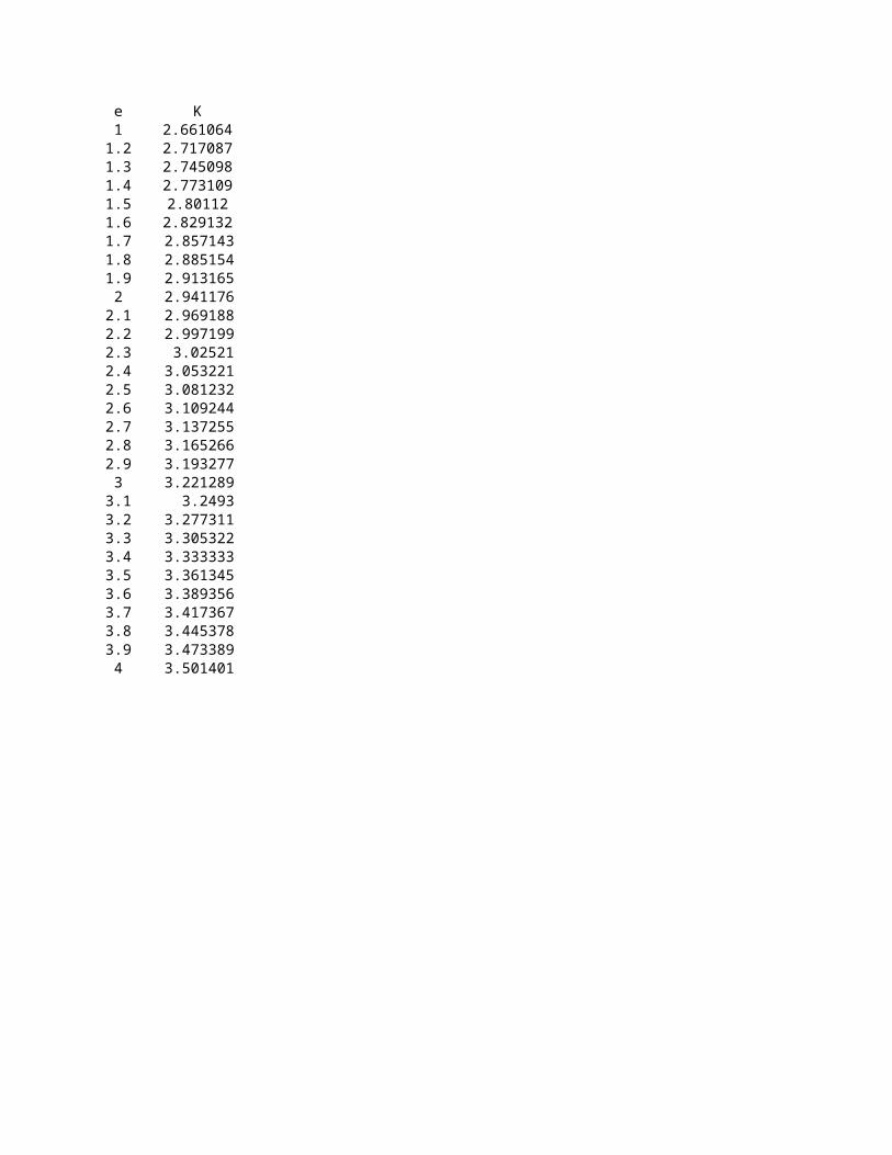
K2.6610642.7170872.7450982.7731092.80112
2.8291322.8571432.8851542.9131652.9411762.9691882.997199
3.025213.0532213.0812323.1092443.1372553.1652663.1932773.221289
3.24933.2773113.3053223.3333333.3613453.3893563.4173673.4453783.4733893.501401