bnwas installation and user manual ver 1.6
DESCRIPTION
BNWASTRANSCRIPT

BNWAS Installation and User Manual
Totem BNWAS Installation and User Manual
© All rights reserved Totem Plus Ltd.

TOTEM PLUS BNWAS Installation and User Manual
Page 2 of 51 Version 1.4
SAFETY INSTRUCTIONS
WARNING
Cabinet contains high voltage, which is HAZARDOUS and can cause
electrical shock. Only qualified personnel are allowed to work inside
the equipment.

TOTEM PLUS BNWAS Installation and User Manual
Page 3 of 51 Version 1.4
List of Changes
Version Issue Date Issued By Remarks
1.0 November 2010 V. Pimenov First Release
1.1 December 2010 V. Pimenov Amendments according to GL comments and recommendations
1.2 January 2011 V. Pimenov Recommended Cable table amended
1.3 April 2011 V. Pimenov Drawings update
1.4 May 2011 V. Pimenov Drawings update
1.5 May 2011 V. Pimenov Drawings update

TOTEM PLUS BNWAS Installation and User Manual
Page 4 of 51 Version 1.4
TABLE OF CONTENTS
1 Preface ________________________________________________________ 8
2 System Overview ________________________________________________ 9
2.1 Equipment List _________________________________________________________________ 10
2.2 Functional Description __________________________________________________________ 10 2.2.1 Operation Modes _________________________________________________________________ 11
2.3 Main Unit _____________________________________________________________________ 12
2.4 Reset Unit _____________________________________________________________________ 13
2.5 Wing Reset Unit ________________________________________________________________ 14
2.6 Alarm Unit ____________________________________________________________________ 15
2.7 I/O Unit _______________________________________________________________________ 16
2.8 Motion Detector ________________________________________________________________ 17
3 Operating Instructions __________________________________________ 18
3.1 The Main Screen _______________________________________________________________ 18
3.2 System setup ___________________________________________________________________ 19 3.2.1 Backup Officers setup __________________________________________________________________ 19 3.2.2 Mode setup ________________________________________________________________________ 20 3.2.3 Dormant Period setup ________________________________________________________________ 20 3.2.4 3d Stage Delay setup _________________________________________________________________ 20 3.2.5 Audio Options setup _________________________________________________________________ 20
4 Installation Manual _____________________________________________ 21
4.1 Location and Installation of the Main Unit __________________________________________ 21 4.1.1 Location of the Main Unit _____________________________________________________________ 21 4.1.2 Installation of the Main Unit ___________________________________________________________ 21
4.2 Location and Installation of I/O Unit _______________________________________________ 21
4.3 Location and Installation of Reset Units _____________________________________________ 22 4.3.1 Location of the Reset Units ____________________________________________________________ 22 4.3.2 Installation of the Reset Units __________________________________________________________ 22
4.4 Location and Installation of the Motion Detectors _____________________________________ 22 4.4.1 Location of the Motion Detectors _______________________________________________________ 22 4.4.2 Motion Detectors Installation __________________________________________________________ 22
4.5 Location and Installation of Alarm Units ____________________________________________ 23 4.5.1 Location of the Alarm Units ___________________________________________________________ 23 4.5.2 Installation of the Alarm Units _________________________________________________________ 23
4.6 Location and Installation of Wing Reset Units ________________________________________ 23 4.6.1 Location of the Wing Reset Units _______________________________________________________ 23 4.6.2 Installation of the Reset Units __________________________________________________________ 23
4.7 External I/O signals connection ___________________________________________________ 24 4.7.1 External Reset ______________________________________________________________________ 24 4.7.2 Auto Pilot On ______________________________________________________________________ 24 4.7.3 System Fault and Power Failure Outputs _________________________________________________ 24 4.7.4 RS485 Output for VDR _______________________________________________________________ 24
4.8 AC and DC power supply _________________________________________________________ 25
5 Maintenance __________________________________________________ 26

TOTEM PLUS BNWAS Installation and User Manual
Page 5 of 51 Version 1.4
6 Spare Parts ___________________________________________________ 27
7 Recommended Cables ___________________________________________ 28
8 Service Manual: Troubleshooting _________________________________ 29
8.1 Power Related Problems __________________________________________________________ 30 8.1.1 Lack of Power ______________________________________________________________________ 30
8.2 Controller Related Problems ______________________________________________________ 31 8.2.1 System is powered but Fault output is active ______________________________________________ 31
8.3 Serial Communication Related Problems ____________________________________________ 32 8.3.1 No Communication with VDR _________________________________________________________ 32
8.4 Motion Detector Related Problems _________________________________________________ 33 8.4.1 Fault: “MOTION 1,2,3, etc.” __________________________________________________________ 33
9 Specification ___________________________________________________ 34
9.1 Main Unit: ____________________________________________________________________ 34
9.2 I/O Unit: ______________________________________________________________________ 34
9.3 Reset Unit _____________________________________________________________________ 35
9.4 Wing Reset Unit ________________________________________________________________ 35
9.5 Alarm Unit: ____________________________________________________________________ 35
9.6 Motion Detector: ________________________________________________________________ 36
10 Technical Drawings ____________________________________________ 37

TOTEM PLUS BNWAS Installation and User Manual
Page 6 of 51 Version 1.4
Table of Figures
Figure 1: System Overview .....................................................................................................................................................................9 Should the bridge be left unattended or if the Officer Of the Watch (OOW) becomes incapacitated, the BNWAS system alerts the OOW in the bridge through visual alarm followed by an audio alarm (First stage alarm). Master and/or other qualified navigating officers would be alerted if OOW is not responding (Second stage alarm). ............................................ 10 If none of the personnel has pressed the Reset button, the system will activate the alarms units in every navigator's cabin and public areas (Third Stage alarm). See time diagram below (Figure 2). .................................................................... 10 Figure 2: Alarm Sequence ..................................................................................................................................................................... 10 Figure 3: Main Unit .............................................................................................................................................................................. 12 Figure 4: Reset Unit ............................................................................................................................................................................. 13 Figure 5: Wing Reset Unit .................................................................................................................................................................... 14 Figure 6: Alarm Unit ............................................................................................................................................................................. 15 Figure 7: I/O Unit ................................................................................................................................................................................ 16 Figure 8: Motion Detector .................................................................................................................................................................... 17 Figure 9: Main Unit Screens ................................................................................................................................................................. 18 Figure 10: Main Unit Dimension Drawings .......................................................................................................................................... 37 Figure 11: Reset Unit Dimension Drawings ......................................................................................................................................... 38 Figure 12: Alarm Unit Dimension Drawings ........................................................................................................................................ 39 Figure 13: I/O Unit Dimension Drawings ............................................................................................................................................. 40 Figure 14: Motion Detector Dimension Drawings ................................................................................................................................ 41 Figure 15: Motion Detector Dimension Drawings ................................................................................................................................ 42 Figure 16: I/O Signal Connections....................................................................................................................................................... 43 Figure 17: Power Supply Connections .................................................................................................................................................. 44 Figure 18 Reset Unit Connections ......................................................................................................................................................... 45 Figure 19: Motion Detector Connections ............................................................................................................................................. 46 Figure 20: Alarm Unit Connections ...................................................................................................................................................... 47 Figure 21 : Alarm Unit Dip Switch Configuration ................................................................................................................................ 48 Figure 22: Wing Reset Unit Connections .............................................................................................................................................. 50 Figure 23: Main Unit Connection ......................................................................................................................................................... 51

TOTEM PLUS BNWAS Installation and User Manual
Page 7 of 51 Version 1.4
Fi
gure 24: I/O Unit Layout ....................................................................................................................................................................... 51

TOTEM PLUS BNWAS Installation and User Manual
Page 8 of 51 Version 1.6
1 Preface
To the Owner
Thank you for purchasing Totem Plus Bridge Navigational Watch Alarm System (Totem BNWAS). Totem
BNWAS is a state of the art maritime product derived from a sophisticated technology that was developed in
Totem Plus. This manual provides the general layout, operation, installation, and maintenance of Totem
BNWAS.
What is BNWAS?
Safety of navigation is the greatest concern for shipping industry. The purpose of the BNWAS is to monitor bridge
activity and detect operator disability which could lead to marine accidents. The system monitors the awareness
of the Officer Of the Watch (OOW) and automatically alerts the Master or another qualified OOW if for any reason
the OOW becomes incapable of performing the OOW’s duties.
Watch Alarm prevents possible collisions or incidents related to the watchman fell asleep or incapacitated.
At the heart of the system is a microcontroller inside the I/O Unit. This unit is interfaced with Main Unit, Reset
Units, Alarm Units, Motion Detectors and external equipment.
The design and construction of the system is in accordance with IMO resolutions:
o MSC.128 (75) – Recommendation on Performance Standards for a Bridge Navigational Watch Alarm
System (BNWAS)
o A.694 (17) – General requirements for shipborne radio equipment, (GMDSS) and for electronic
navigational aids.
o A.686 (17) and A.830 (19), (as applicable) – Code on Alarms and Indicators.
o IEC 62616 Ed 1.0 (2010-02) – Maritime navigation and radio communication equipment and
systems – Bridge Navigational Watch Alarm System (BNWAS) – Methods of testing and required test
results.
o IEC 60945 Ed. 4.0 (2002-08) – Maritime navigation and radio communication equipment and
systems – General requirements – Methods of testing and required test results.
o IEC 62288-1 Ed. 1.0 (2008-07) - Maritime navigation and radio communication equipment and
systems - Presentation of navigation-related information on shipborne navigational displays – General
requirements, methods of testing and required test results
o IEC 61162-1 Ed. 3.0 (2007-04) - Maritime navigation and radio communication equipment and
systems – Digital interfaces – Part 1: Single talker and multiple listeners.
Abbreviations:
BNWAS – Bridge Navigational Watch Alarm System
IMO – International Maritime Organization
OOW – Officer Of the Watch
Td – dormant period
BCC – Bridge Control Console

TOTEM PLUS BNWAS Installation and User Manual
Page 9 of 51 Version 1.6
2 System Overview
Figure 1: System Overview
Totem BNWAS consists of:
1. Main Unit – placed as close as possible to the conning position on the bridge
2. Reset Units – located on the bridge at the workstations for navigating, monitoring, and
maneuvering other than conning position.
3. Wing Reset Units – located on the bridge wings at the maneuvering workstations.
4. Alarm Units – located in the capable officers cabins and public area
5. I/O Unit – located near the Main Unit (inside Bridge Control Console (BCC) or other
convenient place)
6. Motion Detectors – located on the Wheel House ceiling above areas where navigating, monitoring,
and maneuvering take place.
TOTEM PLUS BNWAS Installation and User Manual
Page 10 of 51 Version 1.6
2.1 Equipment List
# Unit Model Entry-level
Standard Scope Of Supply
Optional Total (Max)
1. Main Unit BWS1.0 1 1 - 1
2. Reset Unit RU1.0 - 2 4 6
3. Wing Reset Unit* WR1.0 - - 2 2 (substitutive with Reset Units)
4. Alarm Unit AU1.0 - 4 16 20 (in 7 groups)
5. I/O Unit IO1.0 1 1 - 2
6. Main Unit Cable CB2.0-03
5m 5m 10m 10 m
7. Motion Detector SRX-360N
- 1 6 7 (in 4 groups)
8. AC/DC Power supply PS1.0 - - 1 1
* Up to 10 additional Wing Reset Units can be installed as additional bridge visual indications, audible alarms, and remote audible alarms. The reset button will be blocked in this case.
2.2 Functional Description
The Totem BNWAS system is designed to automatically monitor duty personal activity by following: 1) motion
detectors located strategically around the bridge area 2) OOW operation on the bridge systems capable of
registering physical activity and mental alertness of the OOW (modern radars, ECDIS etc.) 3) reset buttons
located at the bridge working stations.
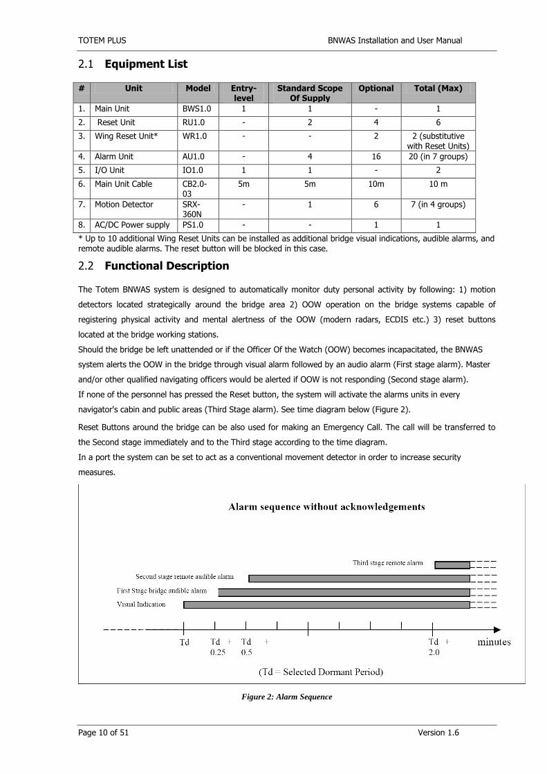
Should the bridge be left unattended or if the Officer Of the Watch (OOW) becomes incapacitated, the BNWAS
system alerts the OOW in the bridge through visual alarm followed by an audio alarm (First stage alarm). Master
and/or other qualified navigating officers would be alerted if OOW is not responding (Second stage alarm).
If none of the personnel has pressed the Reset button, the system will activate the alarms units in every
navigator's cabin and public areas (Third Stage alarm). See time diagram below (Figure 2).
Reset Buttons around the bridge can be also used for making an Emergency Call. The call will be transferred to
the Second stage immediately and to the Third stage according to the time diagram.
In a port the system can be set to act as a conventional movement detector in order to increase security
measures.
Figure 2: Alarm Sequence

TOTEM PLUS BNWAS Installation and User Manual
Page 11 of 51 Version 1.6
Once operational, the watch alarm function remains dormant for a Td period of between 3 and 12 min by setup.
At the end of this dormant period, the alarm system initiates a visual indication on the bridge by flashing light of
all reset buttons. If Reset is not pressed 15 seconds (0.25 of minute) after the visual indication is initiated,
BNWAS will sound a first stage audible alarm on the bridge by activating buzzer synchronized with flashing light.
If the First stage is not reset, BNWAS activates a Second Stage remote visual and audible alarm at the Backup
Officer location (according to setup) 15 seconds after the first stage audible alarm is initiated (0.5 minute after
end of dormant period). If the Second Stage is not reset after 90 seconds to 3 minutes (by setup) after the
second stage alarm is initiated, the system additionally activates the third stage remote visual and audible alarm
at the locations of more crew members that are capable of taking corrective actions (all Officers cabins and Public
Area).
2.2.1 Operation Modes
2.2.1.1 Auto Mode
BNWAS is activated if Autopilot/Track control system is ON and deactivated if Autopilot/Track control system is
OFF. The automatic switch performed by input status connected to relevant Heading/Track control system.
2.2.1.2 Manual Mode
BNWAS is operational regardless of Autopilot/Track control system status.
2.2.1.3 Off Mode
Watch function is not active. Emergency call is possible.
2.2.1.4 Security Mode
When just turned ON the system delays Security mode activation by 30 seconds. The time is given to leave the
bridge without triggering an alarm. During the delay the system gives beep sounds with longer last beep when
activated. If during Security mode a motion detected on the bridge the system triggers bridge alarm and transfers
it automatically to the second stage according to back-up officer setup on the Main Unit. If after 90 seconds to 3
minutes (by setup) nobody reset the system the third stage bridge alarm is activated.
2.2.1.5 Emergency Call
Emergency call can be activated by any of BNWAS reset buttons installed on the bridge including wings and Main
Unit. The OOW can activate the Emergency call by pressing and holding any button for 2 seconds. The call will
be immediately transferred to the second stage alarm (to the backup officer according to the setup of the
system) and if no reset in due time (according to setup) to the third stage (to all officers and public area). A short
press on any reset button will cancel the emergency call and start next dormant period.
2.2.1.6 Fault Indication
Fault LED is activated if one or more faults detected by the system. Entering the Fault page from the Main Menu
Display will reveal which Fault is currently active.

TOTEM PLUS BNWAS Installation and User Manual
Page 12 of 51 Version 1.6
2.3 Main Unit
Totem BNWAS Main Unit consists of four lines LCD screen, illuminated Reset Button, LED mode indicators and
illuminated control buttons. Internal Buzzer provides audible alarm. The Unit is a passive device connected to
microcontroller located in I/O Unit.
Figure 3: Main Unit
Table 1: Main Unit Elements Description
Index Description
1 Auto – Auto mode (system activated/deactivated by specific DI)
2 Manual – Manual mode (system is always On)
3 Security – Security mode (anti-theft alarm is armed. Emergency call is possible )
4 Off – System is in Off condition, no alarms activated (emergency call is possible)
5 Fault – System has a fault condition (list of faults available via menu)
6 Brightness +/- Increase/Decrease brightness of LED’s, buttons and LCD screen
7 LCD screen – four lines LCD panel (presents main screen and submenus)
8 Reset button – flashes when pre-warning is activated, cancels all audible alarms and
starts new dormant period. Activates Emergency Call when pressed for 2 seconds

TOTEM PLUS BNWAS Installation and User Manual
Page 13 of 51 Version 1.6
Index Description
9 Up – go up on presented menu
10 Down – go down on presented menu
11 Back – go back to the previous level of menu
12 Enter – enters the choice
9-12 Buttons in use for password enter
2.4 Reset Unit
The Reset Unit consists of illuminated Reset Button. The Unit is a passive device connected to microcontroller
located in I/O Unit
Figure 4: Reset Unit
Reset button – flashes when pre-warning is activated, cancels all audible alarms and starts new dormant
period. Activates Emergency Call when pressed for 2 seconds

TOTEM PLUS BNWAS Installation and User Manual
Page 14 of 51 Version 1.6
2.5 Wing Reset Unit
Reset Unit consists of illuminated Reset Button and buzzer. The Unit is a passive device connected to
microcontroller located in I/O Unit
Figure 5: Wing Reset Unit
Reset button – flashes when pre-warning is activated, cancels all audible alarms and starts new dormant
period. Activates Emergency Call when pressed for 2 seconds. Buzzer sounds when audible alarm is generated.

TOTEM PLUS BNWAS Installation and User Manual
Page 15 of 51 Version 1.6
2.6 Alarm Unit
Alarm Unit consists of illuminated Reset Button, buzzer, and three LED’s indicators.
Figure 6: Alarm Unit
Buzzer Off button (Yellow) – flashes when second or third stage alarm is activated, cancels the current local
audible alarm when pressed
Active LED (Green) – is active when the system is powered. Blinking when power is supplied but not yet
connected to IO Unit data terminal.
Backup Duty LED (Orange) – indicates that this location has been chosen for second stage bridge alarm to be
transferred (back-up officer). (This can be selected via the Main Unit located on the bridge).
Bridge Alarm LED (Red) – Indicates the bridge alarm has been activated by the system.
TOTEM PLUS BNWAS Installation and User Manual
Page 16 of 51 Version 1.6
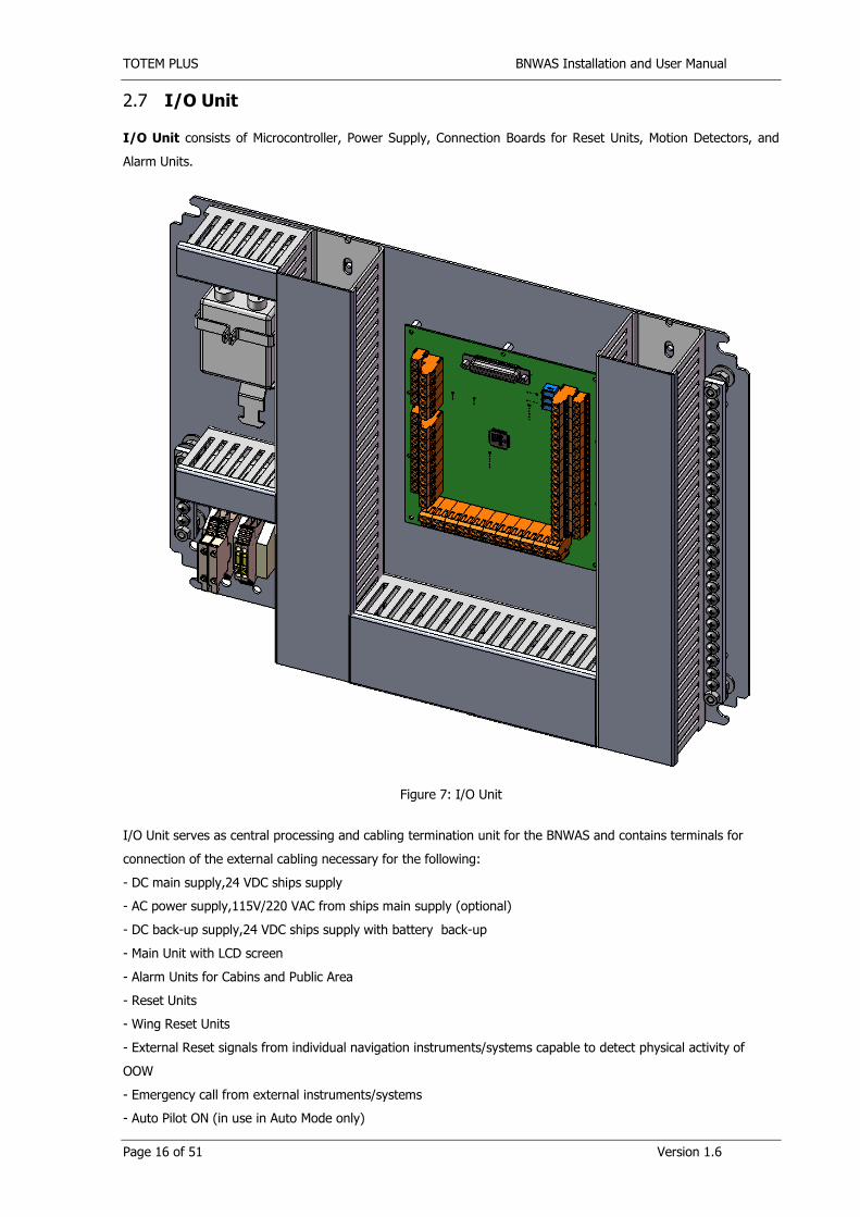
2.7 I/O Unit
I/O Unit consists of Microcontroller, Power Supply, Connection Boards for Reset Units, Motion Detectors, and
Alarm Units.
Figure 7: I/O Unit
I/O Unit serves as central processing and cabling termination unit for the BNWAS and contains terminals for
connection of the external cabling necessary for the following:
- DC main supply,24 VDC ships supply
- AC power supply,115V/220 VAC from ships main supply (optional)
- DC back-up supply,24 VDC ships supply with battery back-up
- Main Unit with LCD screen
- Alarm Units for Cabins and Public Area
- Reset Units
- Wing Reset Units
- External Reset signals from individual navigation instruments/systems capable to detect physical activity of
OOW
- Emergency call from external instruments/systems
- Auto Pilot ON (in use in Auto Mode only)

TOTEM PLUS BNWAS Installation and User Manual
Page 17 of 51 Version 1.6
2.8 Motion Detector
Motion Detector is 360˚ceiling mount 4-elements passive infrared (PIR) detector combined with Micro Wave
(MW).
Figure 8: Motion Detector
The SRX-360 is a combination of 1) 4-element passive infrared motion detector for use in ceiling mount
applications and 2) Micro Wave (MW) detector, providing motion detection by PYRO sensor element and MW
element (based on Doppler effect). Using micro controller for PIR & MW signal analyzing, with Special ASIC
technology for PIR pulse processing, assures “false detection free” operation.
The SRX-360 is equipped with a special hard spherical lens. This lens is the latest development in the security
field and complies with all the new standards requirements. It gives wide coverage patterns, even at low
mounting heights. It is especially immune to sunlight, halogen lights and fluorescent lights and is impervious to
tampering.

TOTEM PLUS BNWAS Installation and User Manual
Page 18 of 51 Version 1.6
3 Operating Instructions
3.1 The Main Screen
The main screen includes a 4-line LCD display of the main information related to BNWAS operation. The Number
on the right side is the time left till the end of dormant period in minutes. When it reaches 99 seconds, the time is
displayed in seconds. The S or M symbol is blinking when time count is running. In the right upper corner there is
a “system running” indicator.
Figure 9: Main Unit Screens
The first two rows of the main screen have no submenus and are for information only:
o Top Row - Duty Officer

TOTEM PLUS BNWAS Installation and User Manual
Page 19 of 51 Version 1.6
System allows one or two backup officers to be assigned at a time. If two officers have been chosen, an
ampersand sign (&) is used to separate names. Possible options are as follows:
CPT – Captain
C/O – Chef Officer
2ND - Second Officer
3RD - Third Officer
4TH – Fourth Officer (Any additional Officer capable of Watch Duty)
5TH – Fifth Officer (Any additional Officer capable of Watch Duty)
o Second Row – Dormant period in minutes
Dormant period (Td) is the delay time before triggering the bridge alarm if no OOW activity is detected
Third and Fourth rows have submenus. Symbol “>” is in use to indicate the row chosen at the moment. Up and
Down arrows are in use to make a choice. The Enter button to enters the sub-menu.
o Third Row - Setup
This item is password protected. There are two different passwords in the system:
The main one allows access to all setups of the system. It is so called Master password.
The secondary password gives access to assign back up officers only. It is Officers password.
o The fourth and last row - Fault
When inside the item list of current faults if any is visible. The faults possible are:
MOTION1 ALARM – System detected trouble in zone 1 of motion detection. The maximum number of
motion detection zones is 4.
AC FAILURE - System detected problem with AC electrical supply. Only 24VDC is available.
DC FAILURE - System detected problem with DC electrical supply. Only AC is available.
3.2 System setup
When Setup is chosen password dialog appears. If wrong password entered or there is more than 40
seconds delay during entering the system returns to the main screen.
When correct Master password is entered full list of options appears (Setup screen – 3). With Officers
password Backup Officer setup screen appears only (Setup screen 3-1).
3.2.1 Backup Officers setup
Backup officers setup has two submenus:
o 1ST BACKUP OFFICER – setup of the first backup officer
o 2ST BACKUP OFFICER – setup of the second backup officer
Inside each of two items there is the same list of backup officers except that second backup officer can be
disabled. The default is Captain as the first backup officer and Chief Officer as the second one. When an
officer has been selected by pressing the Enter button, the display will return to the previous menu (one
level up on the menu tree).

TOTEM PLUS BNWAS Installation and User Manual
Page 20 of 51 Version 1.6
3.2.2 Mode setup
Mode setup screen has list of four possible modes. Each mode has corresponded LED on the
Main Unit panel. The default is Manual. When a mode has been chosen by pressing on Enter button, the system
reacting by moving to one level up on the menu tree – to the Setup screen – 3 and corresponded LED becomes
active.
3.2.3 Dormant Period setup
Dormant Period setup screen has list of four possible Dormant periods: 3, 6, 9, 12 minutes. The default is 12
minutes. When a dormant period has been chosen by pressing on Enter button, the display will return to the
previous menu (Setup screen #3).
3.2.4 3d Stage Delay setup
3d Stage Delay setup screen has list of four possible 3d stage delays: 1.5, 2, 2.5, 3 minutes. This is the time
between Second and Third stage of Bridge alarm. The default is 1.5 minutes. There is an option to disable 3d
stage. If 3d stage is disabled the system will not transfer the alarm to the 3d stage. When a delay has been
chosen by pressing on Enter button, the display will return to the previous menu (Setup screen #3).
3.2.5 Audio Options setup
Audio Option setup screen has list of four possible audio patterns: OPTION 1 … OPTION 4. The sound differs by
length of the alarm sound and pause. Default is OPTION 1: one second sound is active fallowing one second
pause. When an option has been chosen by pressing on Enter button, the display will return to the previous
menu (Setup screen #3).

TOTEM PLUS BNWAS Installation and User Manual
Page 21 of 51 Version 1.6
4 Installation Manual
4.1 Location and Installation of the Main Unit
4.1.1 Location of the Main Unit
The Main Unit should be installed in the vicinity of the bridge conning position where OOW is mostly located
during the watch.
4.1.2 Installation of the Main Unit
1. Find a place on the Bridge console in the vicinity of the bridge conning position.
2. Minimum distance to a magnetic compass must be 500 mm.
3. There must be sufficient space available behind the unit to allow proper cable connection using
D25 connector.
4. Make cut out in the console panel according to the dimension drawings below
5. Make 4 x 5mm holes for the bolts
6. Prepare grounding to be connected to one of the Panel’s bolts
7. Connect the cable to D25 connector on the back side. Note that while you are connecting the
cable the system should be Off.
8. Bolt the panel to the console with M4 nuts, washers, and safety washers.
9. Adjust volume and ascend pattern of the buzzer using trimmers Rt1, Rt2, Rt3 on the Controller
PCB inside I/O unit. The sound shall be audible from all operational positions where the OOW
may reasonably be expected to be stationed.
10. Setup audio option using setup menu. The sound should be distinctive from other alarms on
the bridge.
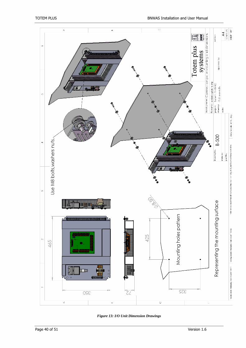
4.2 Location and Installation of I/O Unit
1. I/O Main Unit contains four Mounting Holes, two on top and two on the bottom.
2. Find a place inside console or cabinet. Maximum distance to the Main Unit is 5 m.
3. Make 8.5 mm holes according to the dimension drawings of I/O unit.
4. Bolt the Unit with M8 set of nuts and washers.
5. Cable shields should be connected to the system’s ground bus (GND).
6. System ground bus should be connected with a wire not less than 2 mm2 to the closest earth point
(GND) of the ship.

TOTEM PLUS BNWAS Installation and User Manual
Page 22 of 51 Version 1.6
4.3 Location and Installation of Reset Units
4.3.1 Location of the Reset Units
Reset units should be located only in areas of the bridge providing proper lookout. Flashing visual indication shall
be visible from all operational positions where the OOW may reasonably be expected to be stationed. Reset
buttons shall be easily accessible from the workstations for navigating, maneuvering, and monitoring.
4.3.2 Installation of the Reset Units
1. Make cut-out at the proper location according to the dimension drawings below.
2. Make 4 x 4mm holes for the bolts.
3. Prepare grounding to be connected to one of the Panel’s bolts.
4. Connect the wires according to the electrical drawings below.
5. Bolt the panel to the console with M3 nuts, washers, and safety washers.
4.4 Location and Installation of the Motion Detectors
4.4.1 Location of the Motion Detectors
Detectors should be placed at the bridge workstations (positions at which the crew is expected to be when
performing one of the normal bridge duties) only in areas of the bridge providing proper lookout. The following
workstations should be covered:
Conning position
Main radars
Helmsman position
Bridge Control console
When determining the detector’s location the following should be taken into account:
The surface should be with minimum vibration possible.
The coverage area of one Motion detectors is a circle about 10 m in diameter.
The space around the detector should be clear of obstacles.
Do not install the detector near air conditions, fans, ventilations, heaters, sources of bright light.
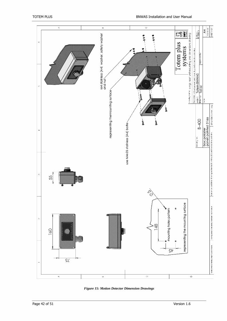
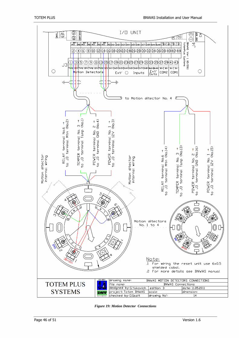
4.4.2 Motion Detectors Installation
1. Remove cover from detector body by loosening the lock-screw about 5mm and turning the
cover counterclockwise.
2. Remove Body from Bracket. The body is removed from base by turning it
counterclockwise.
3. Place the bracket at the ceiling. Insert the cables through the appropriate grooves in the
silicon gasket. Mount the bracket to ceiling using M4 or Sf3.5 self-drilling screws.
4. While the system is powered off, connect the cable to the detector’s bracket according to
electrical drawings below.

TOTEM PLUS BNWAS Installation and User Manual
Page 23 of 51 Version 1.6
5. Place detector body with the sign arrow against the dot market on the bracket. Turn
clockwise until the sign arrow on body placed in front of the sign arrow on bracket.
6. Adjust JP5 jumpers to AND mode.
7. Adjust JP1 jumpers to LED OFF mode (You can keep the LED operational during
commissioning. When navigation started it must be OFF).
8. Adjust sensitivity using JP2, JP6 jumpers and trimmers RV1, RV2. The sensitivity should
be enough to detect hand wave motion.
9. Place the four tabs of the cover in to the matching notches in the base and turn the cover
clockwise until it is fit tightly. Tighten the external lock screw.
10. Check on the Main Unit Screen that there is no fault for specific sensor.
11. Check that when a motion detected it resets dormant period.
12. To cancel false alarm on not existing Motion detectors, Jumper Tampering input to (TAMP)
to 12V
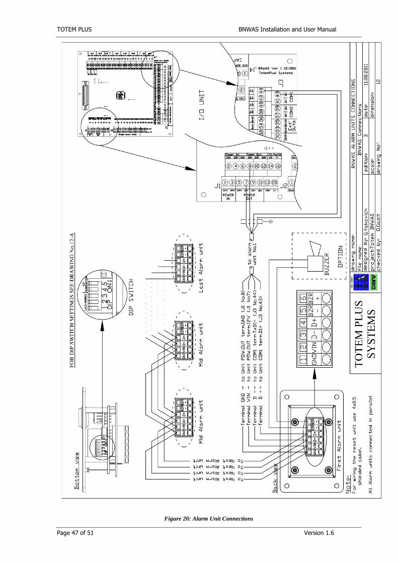
4.5 Location and Installation of Alarm Units
4.5.1 Location of the Alarm Units
Alarm Units should be placed in the locations of the Master, officers and further crew members capable of
taking corrective action as well as in the public area. Connect the Alarm Units in a parallel connection. This
schema allows the connection of a batch of Alarm Units on a single cable loop. Station configuration can be
set using the DIP Switch (illustrated on electrical drawings 12 & 12-A). If two or more Alarm Units are
required for a single location, use the same DIP Switch settings and connect then in parallel. The alarm
volume shall be sufficient for it to be heard throughout the locations above and to wake sleeping personnel.
4.5.2 Installation of the Alarm Units
1. Alarm Units Installation Make cut-out at the proper location according to the dimension drawings below.
2. Make 4 x 4mm holes for the bolts.
3. Prepare grounding to be connected to one of the Panel’s bolts.
4. Connect the wires according to the electrical drawings below.
5. Bolt the panel to the console with M3 nuts, washers, and safety washers.
4.6 Location and Installation of Wing Reset Units
4.6.1 Location of the Wing Reset Units
Open wings should be equipped with Wing Reset Units. It should be located as close as possible to the
maneuvering station. Flashing visual indication shall be visible from all operational positions where the OOW may
reasonably be expected to be stationed. Reset buttons shall be easily accessible from the workstation.
4.6.2 Installation of the Reset Units
1. Wing reset unit is bulkhead mounted.
2. Make 4 x 5 mm holes for the bolts according to dimension drawings below.
3. Open the cover and bolt the panel with M4 stainless nuts, washers, and safety washers.
4. Remove the gland from the box.

TOTEM PLUS BNWAS Installation and User Manual
Page 24 of 51 Version 1.6
5. Insert the wires through the gland.
6. Connect the wires according to the electrical drawings below.
7. If the unit installed as additional visual, audio or remote audio indication it should be connected in
parrallel to the Wing Reset Units except reset Button. Reset Button Should not be connected.
8. Install the gland
9. Adjust volume of the buzzer using trimmer
10. Close the cover and tight the cover screws.
4.7 External I/O signals connection
4.7.1 External Reset
5 External reset inputs provided by the system to connect bridge equipment capable of generating a reset
signal by contact closure. For connection use external I/O signals connection electrical drawings below.
4.7.2 Auto Pilot On
When the system is in Auto mode the On status of the input automatically brings the system to operation
and inhibits it when Off status is set. Contact closure output should be provided by ship’s heading or track
control system. The Auto mode is not suitable for use on a ship conforming with SOLAS V 19.2.2.3 which
requires BNWAS to be in operation whenever the ship is under way at sea. To avoid accidental deactivation,
in this case the input should be short circuit to 24V on the terminals. For connection use external I/O signals
connection electrical drawings below.
4.7.3 System Fault and Power Failure Outputs
System and Power Fault outputs provided to repeat fault indication on a central alarm panel if fitted. The
output circuit is an optocoupler. Optimal load is 3 mA. Maximum load is 50 mA. For right connection polarity
should be observed.
4.7.4 RS485 Output for VDR
RS485 output provides an interface according to IEC 61162-1 for VDR or another registering system. There
are terminals for two systems to be connected simultaneously. For connection use external I/O signals
connection electrical drawings below.
ALR sentence is in use with the following message content:
$BNALR,hhmmss.ss,xxx,A,A,c--c*hh<CR><LF>
– hhmmss.ss: this part left blank (zero field)
– xxx: alarm ID. In BNWAS is designated as "000"
– A: A =Dormant period exceeded
V =Dormant period not exceeded
– A: A =Alarm acknowledged
V =Alarm unacknowledged
–c --c: BNWAS mode :c 1 ;c 2 ;c 3
c 1 =AUT or MAN or OFF
c 2 =Dormant period in min,(03 –12)
c 3 =Alarm stage:1,2 or 3.
TOTEM PLUS BNWAS Installation and User Manual
Page 25 of 51 Version 1.6
Example: $BNALR,,000,A,V,AUT;03;1*hh<CR><L F>
The alarm message shall be sent with any change of the BNWAS settings for mode or dormant period, and
with any activated and reset alarm. For communication control BNWAS should send “heart beat” every 3
minutes where Stage field replaced by “L” = “alive”.
Example:
$BNALR,,000,A,V,AUT;03;L*hh<CR><L F>
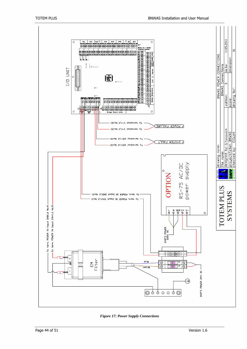
4.8 AC and DC power supply
24VDC or 115/220 VAC (optional) from ships mains serves as main power supply for BNWAS. Provision of
24VDC from battery maintained ships supply source is required as battery back-up power supply for BNWAS
and has to be connected. For connection use Power Supply Connections electrical drawings below.

TOTEM PLUS BNWAS Installation and User Manual
Page 26 of 51 Version 1.6
5 Maintenance
The BNWAS needs no maintenance or calibration. However it is recommended to plug the connectors in and out every year, to prevent oxidation of the contacts. All Units may be cleaned with a light wetted towel.

TOTEM PLUS BNWAS Installation and User Manual
Page 27 of 51 Version 1.6
6 Spare Parts
The spare parts include two fuses F1AL250V 5x20
TOTEM PLUS BNWAS Installation and User Manual
Page 28 of 51 Version 1.6
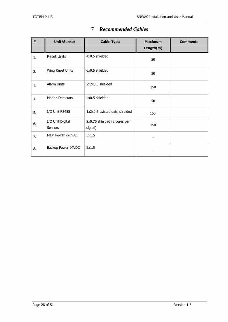
7 Recommended Cables
# Unit/Sensor Cable Type Maximum
Length(m)
Comments
1. Reset Units 4x0.5 shielded 50
2. Wing Reset Units 6x0.5 shielded 50
3. Alarm Units 2x2x0.5 shielded 150
4. Motion Detectors 4x0.5 shielded 50
5. I/O Unit RS485 1x2x0.5 twisted pair, shielded 150
6. I/O Unit Digital
Sensors
2x0.75 shielded (2 cores per
signal) 150
7. Main Power 220VAC 3x1.5 -
8. Backup Power 24VDC 2x1.5 -

TOTEM PLUS BNWAS Installation and User Manual
Page 29 of 51 Version 1.6
8 Service Manual: Troubleshooting
This troubleshooting manual will lead the service technician through a set of questions, which will be used to
diagnose the problem and find a solution. If a step doesn’t solve the problem, continue onward to the next step.
After all steps have been completed, and the problem still persists, please don’t hesitate to consult with a Totem
Plus Technician for further assistance.

TOTEM PLUS BNWAS Installation and User Manual
Page 30 of 51 Version 1.6
8.1 Power Related Problems
8.1.1 Lack of Power
System does not turn on
Check voltage AC voltage
OK?
Check DC voltage on
terminals
OK?
Trouble is in ship’s mains
Replace Power supply
Call Totem Plus
Trouble is in ship’s battery
No
Yes
Yes
Yes
No
No
Check output voltage of
24VDC power supply
inside I/O unit
OK?
Check small yellow
terminal switches
OK?
Switch it ON
No
Yes

TOTEM PLUS BNWAS Installation and User Manual
Page 31 of 51 Version 1.6
8.2 Controller Related Problems
8.2.1 System is powered but Fault output is active
Identify the Origin of the problem Remedy
Controller Watch Dog detecting fault Remove AC and DC power for 3 seconds and put it back for system reset

TOTEM PLUS BNWAS Installation and User Manual
Page 32 of 51 Version 1.6
8.3 Serial Communication Related Problems
8.3.1 No Communication with VDR
Identify the Origin of the problem Remedy
Have you tried to restart the System? Remove AC and DC power for 3 seconds and put it back
for system reset
Is the differential voltage of serial
signals within the IEC 61162
specification? (Should be minimum 2V)
If the output differential voltage is less than 2V check or
steady change Controller
Does it work with a different serial input
of VDR? (Use a port what you know is
working.)
If the port does work with, use a spare serial port, if
available, or replace the serial card
Is there interference?
1. Is the cable shielded and the cores
are twisted?
2. Is the shield connected to BNWAS
only (the talker side)?
1. Replace the cable
2. Connect the shield on the talker side only
If the polarity is correct? Change polarity

TOTEM PLUS BNWAS Installation and User Manual
Page 33 of 51 Version 1.6
8.4 Motion Detector Related Problems
8.4.1 Fault: “MOTION 1,2,3, etc.”
Identify the Origin of the problem
Remedy
Is the trouble circuit is closed?
When System is powered measure voltage
between GND and TAMPER terminals on
the Motion Detectors PCB inside I/O Unit
If there is 12V
Check the cover and body are firmly closed
and locking screw is fully screwed. If
problem persists change the Motion
Detector
If problems persists Change Motion detector port in the PCB if
available or replace the PCB

TOTEM PLUS BNWAS Installation and User Manual
Page 34 of 51 Version 1.6
9 Specification
9.1 Main Unit:
1 illuminated reset button
4 illuminated functional buttons
4 rows x 20 characters LCD display
4 color LED for Mode indication
brightness control (dimmer)
buzzer with adjustable pattern and volume
Dimensions:
D: 29 mm
W: 190 mm
H: 120 mm
Weight: 400 g
Front Face: 0.25 mm Lexan polycarbonate
IP: 22
9.2 I/O Unit:
Controller
5 external reset inputs
“External Emergency call” input
“Auto Pilot On” input
RS485 serial output for VDR (IEC61162-1)
Power Failure and Fault outputs
Up to 8 Motion Detectors (in groups of two)
Up to 6 Reset Units
Up to 20 Alarm Units (in 6 groups)
Dimensions: D: 80 mm
W: 350 mm
H: 465 mm
Weight: 5 kg
Primarily Power supply: 24VDC 0.5A or 115/220 VAC 50/60Hz 0.2/0.1 A (optional)
Backup Power Supply: 24VDC 0.5A

TOTEM PLUS BNWAS Installation and User Manual
Page 35 of 51 Version 1.6
9.3 Reset Unit
One illuminated button
Dimensions: D: 43 mm (does not include button)
W: 85 mm
H: 52.5 mm
Weight: 60 g
IP: 22
9.4 Wing Reset Unit
One illuminated button
Two buzzers
Watertight box
gland
Dimensions: D: 43 mm (does not include button)
W: 160 mm
H: 75 mm (does not include gland)
Weight: 600 g
IP: 56
9.5 Alarm Unit:
Controller
1 illuminated “Buzzer Off” button
3 color LEDs for status indication
buzzer with adjustable volume
Dimensions:
D: 35 mm
W: 85 mm
H: 52.5 mm
Weight: 80 g
IP: 22

TOTEM PLUS BNWAS Installation and User Manual
Page 36 of 51 Version 1.6
9.6 Motion Detector:
PIR and MW sensor with 36coverage pattern
Up to 3.6m mounting height
36/20m diameter coverage when mounted at 3.6m
Fully sealed sensor chamber
VLSI Technology (Very Large Scale Integration)
Omni directional 4 Element Pyro Sensor
Microwave detection based on Doppler concept
Unique Microwave Motion Sensor Module with microstrip patch antenna
AND &OR alarm signal selection
2-way Microwave sensitivity adjustment
2-way PIR sensitivity adjustment
Hard Spherical Lens 36coverage
Bidirectional temperature compensation
Fluorescent light stability
RFI &EMI Immunity.
Dimensions:
D: 58.5 mm
Diameter: 131 mm
Weight: 200 g
IP: 22

TOTEM PLUS BNWAS Installation and User Manual
Page 37 of 51 Version 1.6
10 Technical Drawings
Figure 10: Main Unit Dimension Drawings

TOTEM PLUS BNWAS Installation and User Manual
Page 38 of 51 Version 1.6
Figure 11: Reset Unit Dimension Drawings

TOTEM PLUS BNWAS Installation and User Manual
Page 39 of 51 Version 1.6
Figure 12: Alarm Unit Dimension Drawings
TOTEM PLUS BNWAS Installation and User Manual
Page 40 of 51 Version 1.6
Figure 13: I/O Unit Dimension Drawings

TOTEM PLUS BNWAS Installation and User Manual
Page 41 of 51 Version 1.6
Figure 14: Motion Detector Dimension Drawings
TOTEM PLUS BNWAS Installation and User Manual
Page 42 of 51 Version 1.6
Figure 15: Motion Detector Dimension Drawings

TOTEM PLUS BNWAS Installation and User Manual
Page 43 of 51 Version 1.6
Figure 16: I/O Signal Connections
TOTEM PLUS BNWAS Installation and User Manual
Page 44 of 51 Version 1.6
Figure 17: Power Supply Connections

TOTEM PLUS BNWAS Installation and User Manual
Page 45 of 51 Version 1.6
Figure 18 Reset Unit Connections
TOTEM PLUS BNWAS Installation and User Manual
Page 46 of 51 Version 1.6
Figure 19: Motion Detector Connections
TOTEM PLUS BNWAS Installation and User Manual
Page 47 of 51 Version 1.6
Figure 20: Alarm Unit Connections

TOTEM PLUS BNWAS Installation and User Manual
Page 48 of 51 Version 1.6
Figure 21 : Alarm Unit Dip Switch Configuration

TOTEM PLUS BNWAS Installation and User Manual
Page 49 of 51 Version 1.6

TOTEM PLUS BNWAS Installation and User Manual
Page 50 of 51 Version 1.6
Figure 22: Wing Reset Unit Connections

TOTEM PLUS BNWAS Installation and User Manual
Page 51 of 51 Version 1.6
Figure 23: Main Unit Connection
Figure 24: I/O Unit Layout