bolero 1 bolero 2 - baristashopen - best coffee beans from ... · pdf filecopyright bravilor...
TRANSCRIPT

�Copyright Bravilor Bonamat B.V.
Bolero 1Bolero 2
OPERATING PRINCIPLE

�Copyright Bravilor Bonamat B.V.
© 2011 Bravilor® Bonamat®All rights reserved.
No part of this document may be copied and/or published by means of printing, photocopying, microfilmingor by any other means whatsoever without the prior written consent of the manufacturer. This applies equallyto the associated drawings and/or diagrams.
The information contained in this document is based on general data concerning the construction,materials characteristics and working methods known to us at the time of publication, so we reserve the rightto make changes without notice. For this reason the instructions contained in this document should betreated as a guide to the installation, maintenance and repair, of the machines indicated on the front cover.
This document applies to the machines in its standard form. The manufacturer therefore accepts noliability for any damage or injury arising from specifications that deviate from the standard form of themachines as supplied to you.
Every possible care has been taken in the production of this document but the manufacturer accepts noliability for any errors in this document or for any consequences arising therefrom.

�Copyright Bravilor Bonamat B.V.
1. OPERATING PRINCIPLE 1. . . . . . . . . . . . . . . . . . . . . . . . . . . . . . . . . . . . . . . . . . 1.1 General operation 1. . . . . . . . . . . . . . . . . . . . . . . . . . . . . . . . . . . . . . . . . . . . . . . . . . . . . . 1.2 Water dosing system 2. . . . . . . . . . . . . . . . . . . . . . . . . . . . . . . . . . . . . . . . . . . . . . . . . . . 1.3 Start−up 4. . . . . . . . . . . . . . . . . . . . . . . . . . . . . . . . . . . . . . . . . . . . . . . . . . . . . . . . . . . . . . .
1.3.1 Initialisation 4. . . . . . . . . . . . . . . . . . . . . . . . . . . . . . . . . . . . . . . . . . . . . . . . . . . . . . . . 1.3.2 Filling 4. . . . . . . . . . . . . . . . . . . . . . . . . . . . . . . . . . . . . . . . . . . . . . . . . . . . . . . . . . . . . 1.3.3 Heating 4. . . . . . . . . . . . . . . . . . . . . . . . . . . . . . . . . . . . . . . . . . . . . . . . . . . . . . . . . . . . 1.3.4 Dosing 5. . . . . . . . . . . . . . . . . . . . . . . . . . . . . . . . . . . . . . . . . . . . . . . . . . . . . . . . . . . .
1.4 Powder dosing system 6. . . . . . . . . . . . . . . . . . . . . . . . . . . . . . . . . . . . . . . . . . . . . . . . . 1.5 Mixing system 7. . . . . . . . . . . . . . . . . . . . . . . . . . . . . . . . . . . . . . . . . . . . . . . . . . . . . . . . . 1.6 Ventilation system 7. . . . . . . . . . . . . . . . . . . . . . . . . . . . . . . . . . . . . . . . . . . . . . . . . . . . . 1.7 Operating system 8. . . . . . . . . . . . . . . . . . . . . . . . . . . . . . . . . . . . . . . . . . . . . . . . . . . . . .
1.7.1 Keyboard 8. . . . . . . . . . . . . . . . . . . . . . . . . . . . . . . . . . . . . . . . . . . . . . . . . . . . . . . . . . 1.7.2 Main board 8. . . . . . . . . . . . . . . . . . . . . . . . . . . . . . . . . . . . . . . . . . . . . . . . . . . . . . . . .
1.8 Hardware protections 9. . . . . . . . . . . . . . . . . . . . . . . . . . . . . . . . . . . . . . . . . . . . . . . . . . 1.8.1 Back−flow protection 9. . . . . . . . . . . . . . . . . . . . . . . . . . . . . . . . . . . . . . . . . . . . . . . . 1.8.2 Boiling protection 9. . . . . . . . . . . . . . . . . . . . . . . . . . . . . . . . . . . . . . . . . . . . . . . . . . . 1.8.3 Overflow protection 9. . . . . . . . . . . . . . . . . . . . . . . . . . . . . . . . . . . . . . . . . . . . . . . . .
1.9 Software protection 10. . . . . . . . . . . . . . . . . . . . . . . . . . . . . . . . . . . . . . . . . . . . . . . . . . . . 1.10 Programming 11. . . . . . . . . . . . . . . . . . . . . . . . . . . . . . . . . . . . . . . . . . . . . . . . . . . . . . . . . .
�Copyright Bravilor Bonamat B.V.
Fig. 1 The water dosing system 2. . . . . . . . . . . . . . . . . . . . . . . . . . . . . . . . . . . . . . . . . . . . . . . . . . . . . . . . Fig. 2 Float tank, complete 2. . . . . . . . . . . . . . . . . . . . . . . . . . . . . . . . . . . . . . . . . . . . . . . . . . . . . . . . . . . . Fig. 3 Pump motor + rotor 5. . . . . . . . . . . . . . . . . . . . . . . . . . . . . . . . . . . . . . . . . . . . . . . . . . . . . . . . . . . . . Fig. 4 Pump housing 5. . . . . . . . . . . . . . . . . . . . . . . . . . . . . . . . . . . . . . . . . . . . . . . . . . . . . . . . . . . . . . . . . . Fig. 5 Encoder 5. . . . . . . . . . . . . . . . . . . . . . . . . . . . . . . . . . . . . . . . . . . . . . . . . . . . . . . . . . . . . . . . . . . . . . . Fig. 6 Exhaust hood 7. . . . . . . . . . . . . . . . . . . . . . . . . . . . . . . . . . . . . . . . . . . . . . . . . . . . . . . . . . . . . . . . . . Fig. 7 Mixing unit 7. . . . . . . . . . . . . . . . . . . . . . . . . . . . . . . . . . . . . . . . . . . . . . . . . . . . . . . . . . . . . . . . . . . . . Fig. 8 Ventilation system 7. . . . . . . . . . . . . . . . . . . . . . . . . . . . . . . . . . . . . . . . . . . . . . . . . . . . . . . . . . . . . . Fig. 9 LCD display with error message 10. . . . . . . . . . . . . . . . . . . . . . . . . . . . . . . . . . . . . . . . . . . . . . . . . . Fig. 10 Door open 11. . . . . . . . . . . . . . . . . . . . . . . . . . . . . . . . . . . . . . . . . . . . . . . . . . . . . . . . . . . . . . . . . . . . Fig. 11 Programming key 11. . . . . . . . . . . . . . . . . . . . . . . . . . . . . . . . . . . . . . . . . . . . . . . . . . . . . . . . . . . . . . Fig. 12 Total counter 11. . . . . . . . . . . . . . . . . . . . . . . . . . . . . . . . . . . . . . . . . . . . . . . . . . . . . . . . . . . . . . . . . . Fig. 13 Day counter 11. . . . . . . . . . . . . . . . . . . . . . . . . . . . . . . . . . . . . . . . . . . . . . . . . . . . . . . . . . . . . . . . . . . Fig. 14 Day counter to zero 11. . . . . . . . . . . . . . . . . . . . . . . . . . . . . . . . . . . . . . . . . . . . . . . . . . . . . . . . . . . . Fig. 15 General selection screen 11. . . . . . . . . . . . . . . . . . . . . . . . . . . . . . . . . . . . . . . . . . . . . . . . . . . . . . . Fig. 16 Descaling symbol 12. . . . . . . . . . . . . . . . . . . . . . . . . . . . . . . . . . . . . . . . . . . . . . . . . . . . . . . . . . . . . . Fig. 17 Programming key / Door closed 12. . . . . . . . . . . . . . . . . . . . . . . . . . . . . . . . . . . . . . . . . . . . . . . . .

�Copyright Bravilor Bonamat B.V.
1. OPERATING PRINCIPLE
1.1 General operationThe machine works according to a pump systemdeveloped by Bravilor Bonamat. This system hasthe following advantages:� The components that are responsible for the
correct dosing of the water are housed in a coldwater unit. As a result, the largest cause of faultswith machines, the formation of scale on thedosing valves, is limited to a minimum.
� The float that regulates the water level is alsolocated in the cold−water circuit. This is anotherreason why the formation of scale is limited to aminimum.
�Copyright Bravilor Bonamat B.V.
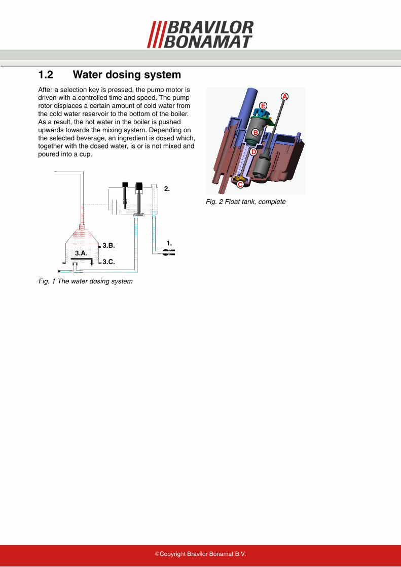
1.2 Water dosing systemAfter a selection key is pressed, the pump motor isdriven with a controlled time and speed. The pumprotor displaces a certain amount of cold water fromthe cold water reservoir to the bottom of the boiler.As a result, the hot water in the boiler is pushedupwards towards the mixing system. Depending onthe selected beverage, an ingredient is dosed which,together with the dosed water, is or is not mixed andpoured into a cup.
ÁÁÁÁÁÁÁÁÁÁÁÁ
ÁÁÁÁÁÁÁÁÁÁ
3.A.
1.
2.
3.B.
3.C.
Fig. 1 The water dosing system
ÁÁÁÁ
C
Á
ÁÁÁÁ
ÁÁ
A
B
ÁÁD
E
Fig. 2 Float tank, complete

�Copyright Bravilor Bonamat B.V.
The water dosing system consists of the followingmain components:1. Magnetic valve2. Float tank, complete
A. FloatB. Pump motorC.Pump rotorD.Pump housingE. Encoder
3. Element complete (boiler)A. ElementB. Temperature sensor high (NTC)C.Temperature sensor low (NTC)
�Copyright Bravilor Bonamat B.V.
1.3 Start−up1.3.1 Initialisation
The machine is switched on with the main switch.On the LCD (Liquid Crystal Display) the followingappear in succession:� all symbols that the display can show.
� the version number of the software(microprocessor) loaded from the factory.
� the version of the software table (Eeprom), alsoloaded from the factory.
This process takes approx. 3 seconds and ends withthe steaming cup in the LCD display to show thatthis phase has successfully finished.
1.3.2 Filling
The float tank and the boiler are connected by asiphon hose. Together, they form a communicatingvessel. When the machine is switched on for thefirst time, the float tank (fig.2 ) will be empty and thefloat (fig.2 A.) will be low.� The magnetic valve (fig.1 ,1.) is opened and fills
water in the float tank with a speed of 2 litres perminute, depending on the pressure.
� The water in the float tank flows to the boilerthrough the hose under the float tank.
� After the water level has pushed the floatupwards, the water level in the float tank is thesame as that of the boiler. The magnetic valve isswitched off.
� A signal sounds when the level of the float isreached.
Please note:Because the float tank is filled faster than the water”drops” to the boiler, the filling process will be madewith short intervals.
1.3.3 Heating
After the system is completely filled with water,element (fig.1 ,3.A.) is switched on by means of arelay in the machine.
The temperature sensor (fig.1 ,3.B.), which ismounted on the outside of the boiler, measures theactual temperature of the water. This ensures thatthe water in the boiler is heated to the desired finaltemperature.
During the heating, a thermometer flashes in theLCD display. This indicates that the machine is notyet ready for use.
The temperature sensor is of the type NTC(Negative Temperature Coefficient). The higher themeasured temperature the lower the resistance ofthe sensor.
Hot water has a lower specific weight than coldwater. As a result, the hot water in the boiler will notwant to flow back to the float tank through thesiphon hose at the bottom. That part of the systemwill therefore remain cold. The latter is veryimportant because precisely the parts of the floattank are sensitive for scale.
The temperature sensor is mounted on the outsideof the boiler. As a result, there is no feed−through inthe wall and therefore there cannot be anylong−term leakage.
This measurement is less direct. This is why thetemperature is regulated proportionally. The heatingswitches on for a certain time and off for a certaintime.
After the period that the heating has been off, ameasurement is made. The next time, the heatingwill be on for longer or shorter.
The higher the temperature in the boiler, the shorterthe moments become that the element is on, andthe longer the intermediate time becomes. In thisway, an accurate temperature is obtained in theboiler.
There is a second temperature sensor on the boiler(fig.1 ,3.C.). This sensor monitors the outlettemperature of the dosed water. If this sensormeasures a too low temperature, the machine isblocked. No more water is dosed.
�Copyright Bravilor Bonamat B.V.
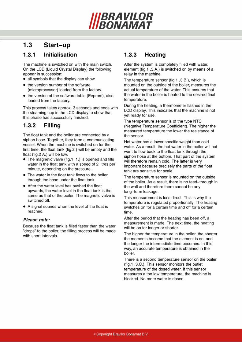
1.3.4 DosingDosing is allowed when:� The float is in the top position.
� After a selection key is pressed, the pump motor(fig.3 ) is driven for a certain time, depending onthe programmed amount, with a certain speed(number of revolutions).
Fig. 3 Pump motor + rotor
� The pump rotor rotates in the pump chamber,which is filled with water. This is formed by thebottom of the float tank and the underneath of thepump housing (fig.4 ).
Fig. 4 Pump housing
� The pump rotor pumps the water out of the pumpchamber, through the siphon hose in the bottomof the boiler.
� As a result, the hot water in the boiler is pushedout of the boiler.
� The float and the magnetic valve ensure that thelevel in the float tank is maintained and that waterremains in the pump chamber.
The volume of the displaced liquid (yield) is mainlydetermined by the time and speed of the pumpmotor.
The time that the motor is on is regulated from thesoftware and is very accurate.
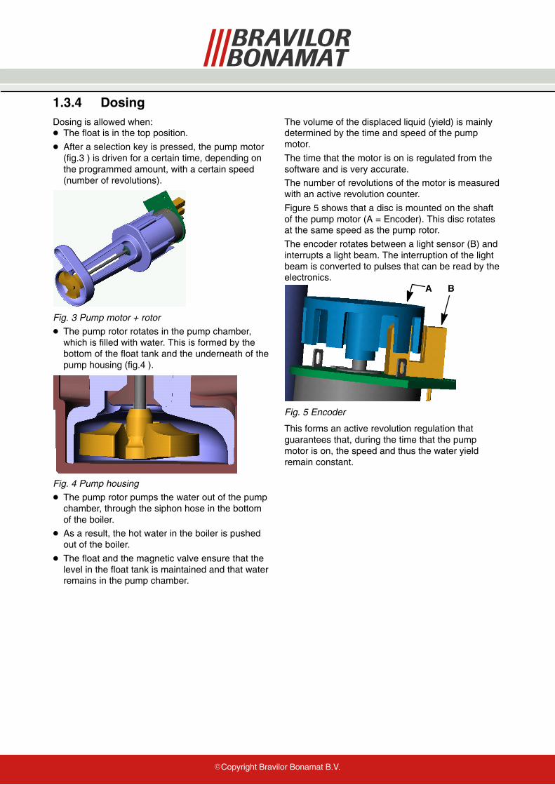
The number of revolutions of the motor is measuredwith an active revolution counter.
Figure 5 shows that a disc is mounted on the shaftof the pump motor (A = Encoder). This disc rotatesat the same speed as the pump rotor.
The encoder rotates between a light sensor (B) andinterrupts a light beam. The interruption of the lightbeam is converted to pulses that can be read by theelectronics.
A B
Fig. 5 Encoder
This forms an active revolution regulation thatguarantees that, during the time that the pumpmotor is on, the speed and thus the water yieldremain constant.
�Copyright Bravilor Bonamat B.V.
1.4 Powder dosing systemThe powder dosing system consists of an ingredientholder (canister) that is driven by a motor (canistermotor).
After the start key is pressed, the canister motor willrotate after a certain delay. This motor drives aworm, which transports the ingredient to the canisteroutlet.
The control of the canister motor makes it possibleto regulate timing and dosing speed independently.As a result, the ingredient can be poured into themixer at the same time that the water flows out.However, the canister motor will stop slightly earlierthan the water, to rinse the mixing jug clean.
Depending on the type of ingredient, “beatersprings” are used in the canister. These springsensure that less tunnel formation occurs. This is thecaking of ingredient against the walls.

�Copyright Bravilor Bonamat B.V.
1.5 Mixing systemThe mixing unit (fig.7 ) mixes the hot water and theingredient. After a selection key is pressed, thewater will be dosed in the mixing chamber after acertain delay. The product falls into the mixingchamber from above. Depending on the selectedbeverage, the mixer will start to rotate with a certainnumber of revolutions.
An exhaust opening is mounted on top of the mixingchamber (fig.6 ). This cover has an opening at therear, which is pressed into an exhaust openingthrough the sheet−metal work. The function of thisexhaust system is to ensure that vapour from themixing chamber does not get the chance to reachthe ingredient holder outlet.
Fig. 6 Exhaust hood
Fig. 7 Mixing unit
1.6 Ventilation systemThe ventilation system (fig.8 ) removes the steam,that developes during dosing. So the settling ofwarm steam and condensation in the mixingchamber will be prevented. Therefore the mixingchamber will get less dirty.
Fig. 8 Ventilation system
�Copyright Bravilor Bonamat B.V.
1.7 Operating systemThe operating system consists of a:� Keyboard
� Main board
1.7.1 Keyboard
The keyboard is located on the front of the machineand contains various keys and the display. Thisboard contains inputs and outputs of the machineand the microprocessor with memory. Savedsettings such as the dosing quantities, counters, etc.are stored here. When this circuit board is replaced,the customer−specific settings will be lost.A flat cable connects the keyboard to the mainboard in the machine.
1.7.2 Main board
The main board is located on the rear inside themachine and it is supplied from an externaltransformer. This board contains a number ofcomponents that convert the alternating current ofthe transformer into 24 V direct current. The mainboard also contains the relay for controlling theheating element.
�Copyright Bravilor Bonamat B.V.
1.8 Hardware protectionsThe machine is equipped with a number of hardwareprotections. These protections ensure that nodangerous situations can arise, such as overheatingand/or water in the machine.
1.8.1 Back−flow protection
The water from the magnetic valve is sprayedagainst the cover through a pipe in the cold watertank. Then it flows into the cold water tank. In thisway, water is prevented from flowing back into thesystem and getting into the water system when thewater pressure is released from the magnetic valve.
1.8.2 Boiling protection
The boiling−dry protection is mounted on the outsideof the boiler by means of two Klixons. If the boiler,for whatever reason, is not switched off by thecontrol, the Klixons make sure that the voltage onthe element is mechanically switched off to preventoverheating.
1.8.3 Overflow protection
This protection is located in the cold water tank andensures that, when the water level is too high,excess water is passed through the overflow hose atthe bottom of the machine.

�Copyright Bravilor Bonamat B.V.
1.9 Software protectionThe machine has been equipped with a number ofsoftware protections; the software monitors all inputsand outputs of the machine throughout the process.If non−allowed situations arise, the software willintervene. This intervention results in the machinebeing switched off and an error message beingshown on the display.
Fig. 9 LCD display with error message
ERROR LIST
Error 1 not applicable
Error 2 Temperature in boiler too high:− If the temperature sensor (NTC) measures
a value that is outside its range (0 Ohm orinfinity), the machine is switched off and’Error 2’ appears in the LCD display. Thisalso applies if the boiling protection (seehardware protection) is activated.
Error 3 not applicable
Error 4 not applicable
Error 5 not applicable
Error 6 Magnetic valve opened too long:− If, for whatever reason, the process of filling
the float tank takes too long, the machine isswitched off and ’Error 6’ appears in the LCDdisplay.
Error 7 Wrong Chip card:− In a number of cases, it is possible to place a
chip card in a chip card reader. This ispresent on the keyboard. Any data presentcan be downloaded or uploaded. If thesoftware on this chip card does notcorrespond with the software in the machine,’Error 7’ appears in the LCD display.
Error 8 Communication error between both prints:− There is constant communication during
machine start−up and during use. This isdone via the flatcable between the keyboardand the main board. If communication isimpossible, ’Error 8’ appears in the LCDdisplay.
Error 9 Pump motor rotates too slow or does notrotate at all:
− The pump motor is rotating during machinestart−up and during use. The light sensordetects no or too little pulses and ’Error 9’ willappear in the LCD display.
�Copyright Bravilor Bonamat B.V.
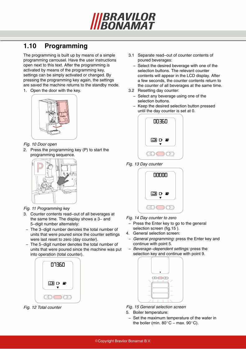
1.10 ProgrammingThe programming is built up by means of a simpleprogramming carrousel. Have the user instructionsopen next to this text. After the programming isactivated by means of the programming key,settings can be simply activated or changed. Bypressing the programming key again, the settingsare saved the machine returns to the standby mode.1. Open the door with the key.
Fig. 10 Door open2. Press the programming key (P) to start the
programming sequence.
Fig. 11 Programming key3. Counter contents read−out of all beverages at
the same time. The display shows a 3− and5−digit number alternately:
− The 3−digit number denotes the total number ofunits that were poured since the counter settingswere last reset to zero (day counter).
− The 5−digit number denotes the total number ofunits that were poured since the machine was putinto operation (total counter).
Fig. 12 Total counter
3.1 Separate read−out of counter contents ofpoured beverages:
− Select the desired beverage with one of theselection buttons. The relevant countercontents will appear in the LCD display. Aftera few seconds, the counter contents return tothe counter of all beverages at the same time.
3.2 Resetting day counter:− Select any beverage using one of the
selection buttons.− Keep the desired selection button pressed
until the day counter is set at 0.
Fig. 13 Day counter
Fig. 14 Day counter to zero− Press the Enter key to go to the general
selection screen (fig.15 ).4. General selection screen:− General programming: press the Enter key and
continue with point 5.− Beverage−dependent settings: press the
selection key and continue with point 9.
Fig. 15 General selection screen5. Boiler temperature:− Set the maximum temperature of the water in
the boiler (min. 80�C − max. 90�C).
�Copyright Bravilor Bonamat B.V.
6. Descaling signal:− Ask your local water company about the hardness
of the water supply. Always select the rightsetting. The default setting of the machine isposition 3 (1000L). The machine continuouslyregisters the time that the inlet valve is open andtherefore the number of litres of water that haspassed through the system. When the number ofregistered litres is greater than or equal to theprogrammed value, the descaling symbol in theLCD display starts to flash.
Fig. 16 Descaling symbol7. Energy−saving mode:− Setting the number of minutes/hours, after which
the machine must switch over to the ECO mode.All functions such as boiler, ventilator anddisplay illumination switch off and [ECO]appears in the LCD display. The next time that aselection key is pressed, the machine switcheson again. Depending on the switch−off time, itcan take a few minutes before the machine isready for use again.
8. Copy Card:− Customer specific settings can be copied on the
chipcard, whereupon these can be downloadedto other equivalent machines.� The procedure can be found on the extranet
“Special Codes”.
9. General selection screen.10. Amount drink dependent:− For the mug and jug selection buttons.− Setting the amount of water in ml. The software
will convert a larger amount to a longer pumpingtime. If the amount of water is changed, thebasic strength is automatically adapted, so thatthe strength increases or decreasesproportionally.
10.1 Block dosing:− Decrease the value to the minimum. The
display will show ’OFF’.11. Basic strength drink dependent:− Setting amount of ingredient (in %). The
software translates the programmed percentageto the speed of the canister motor and thereforethe strength of the ingredient. (See ingredientsheet).
12. Mixer on/off:− By switching the mixer ON, the beverage is
mixed and, with coffee, a layer of cream isobtained on the top. If this is not desired, andblack coffee is required, set this option to OFF.With other ingredients such as cocoa, the mixermust always be set to ON to prevent clogging.
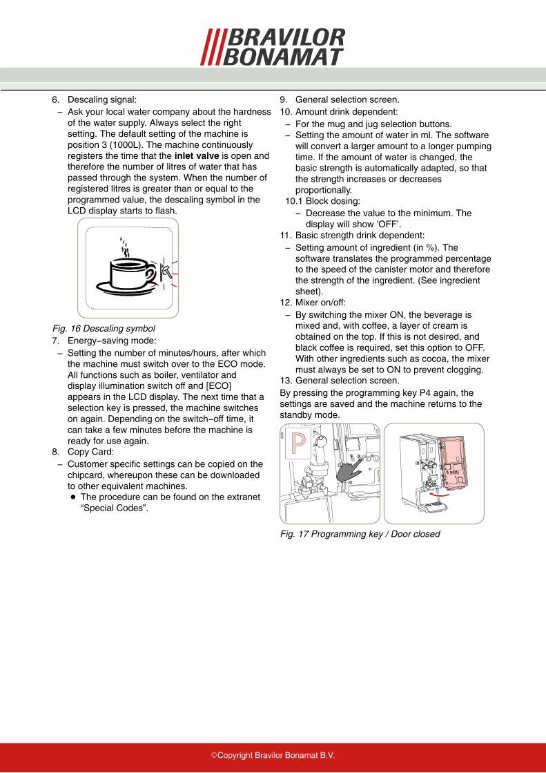
13. General selection screen.By pressing the programming key P4 again, thesettings are saved and the machine returns to thestandby mode.
Fig. 17 Programming key / Door closed

�Copyright Bravilor Bonamat B.V.
© 07−2011