bollard assessment final - city of albuquerque · coa project no. 5015.00 multi-use trail bollard...
TRANSCRIPT

CITY OF ALBUQUERQUE CITY WIDE-ON CALL ENGINEERING SERVICES
(TRANSPORTATION & STORM DRAINAGE) 5015.00
TASK 3 MULTI-USE TRAIL BOLLARD ASSESSMENT
Prepared For:
Prepared By:
September 5, 2013

CoA Project Number 5015.00 Multi-Use Trail Bollard Assessment
September 5, 2013 i
Table of Contents Page
1. Introduction ............................................................................................................................................ 1
2. AASHTO Criteria ...................................................................................................................................... 1
2.1 Multi‐Use Trails and Bollards ........................................................................................................... 1
2.2 AASHTO and MUTCD Bollard Guidelines ......................................................................................... 2
3. City of Albuquerque Bollard Installations............................................................................................... 3
4. National Guidance .................................................................................................................................. 9
5. Summary and Recommendations ........................................................................................................ 10
List of Figures Page
Figure 1: Bear Canyon Arroyo (East Entrance) .............................................................................................. 5
Figure 2: Bear Canyon Arroyo (West Entrance) ............................................................................................ 6
Figure 3: Bear Canyon Arroyo Trail ............................................................................................................... 7
Figure 4: Gail Ryba Bridge ............................................................................................................................. 8
Figure 5: Recommended Practice for Bollard Placement ........................................................................... 11
List of Tables Page
Table 1: Multi‐Use Trail Design Criteria Summary ........................................................................................ 4
List of Appendices
Appendix A: City of Albuquerque Standard Detail
Appendix B: Agency Bollard Standard Details
Appendix C: GARTC Draft Bollard Policy

CoA Project No. 5015.00 Multi-Use Trail Bollard Assessment
September 5, 2013 1
1. INTRODUCTION
The purpose of this report is to identify relevant design criteria for bollards on multi‐use trail facilities, review the installation of bollards on multi‐use trails at several locations identified by the City, and develop best practices for implementation by the City of Albuquerque.
Common problems associated with bollards and multi‐use trail facilities in Albuquerque include the following:
Bollards present a collision hazard when placed on a multi‐use trail.
Inconsistent installations lead to user confusion and do not meet a consistent user expectation.
Inadequate spacing between bollards results in users being unable to access facilities and don not comply with ADA requirements.
Removable bollards are illegally removed from their locations when not locked.
When not in place, removable bollards have a 1‐inch high collar that becomes a trip hazard.
When bollards are not in place, unauthorized motorized vehicles may utilize multi‐use facilities.
2. AASHTO CRITERIA
2.1 Multi‐Use Trails and Bollards
Bollards are a commonly used method of controlling vehicular access to multi‐use trails. However, per the American Association of State Highway and Transportation Officials (AASHTO) Guide for the Development of Bicycle Facilities, 2012 (Fourth Edition):
“The routine use of bollards and other similar barriers to restrict motor vehicle traffic is not recommended. Bollards should not be used unless there is a documented history of unauthorized intrusion by motor vehicles. Barriers such as bollards, fences, or other similar devices create permanent obstacles to path users.”
“Furthermore, physical barriers are often ineffective at the job they were intended for – keeping out motorized traffic. People who are determined to use the path illegally will often find a way around the physical barrier, damaging path structures and adjacent vegetation. A three‐step approach may be used to prevent unauthorized motor vehicle entry to shared use paths:
1. Post signs identifying the entry as a shared use path and regulatory signs prohibiting motor vehicle entry.
2. Design the path entry locations so that it does not look like a vehicle access and make intentional access by unauthorized users difficult. A preferred method of restricting entry of motor vehicles is to split the entry way into two sections separated by low landscaping.
3. Assess whether signing and path entry design prevents or reduces unauthorized traffic to tolerable levels. If motor vehicle incursion is isolated to a specific location, consider targeted surveillance and enforcement.”
There are no standards or recommended guidelines that have been established to identify a threshold for what constitutes a history of unauthorized motorized vehicular use on a multi‐use trail, and the City of Albuquerque does not have a policy for when bollards should be considered.

CoA Project No. 5015.00 Multi-Use Trail Bollard Assessment
September 5, 2013 2
2.2 AASHTO and MUTCD Bollard Guidelines
If a need for the implementation of bollards for a multi‐use trail is identified, AASHTO has set forth several guidelines for the design of vertical barriers to make them as compatible as possible with the needs of path users and bicyclists. It should be noted that the parameters listed below are recommended practices and not design standards.
Bollards should be marked with a retroreflectorized material on both sides or with appropriate object markers, per Section 9B.26 of the Manual of Uniform Traffic Control Devices (MUTCD).
o MUTCD Section 9B.26 Object Markers
Fixed objects adjacent to shared‐use paths may be marked with Type 1, Type 2, or Type 3 object markers. If the object maker is not intended to also be seen by motorists, a small version of the Type 3 object marker may be used.
Standard:
Obstructions in the traveled way of a shared‐use path shall be marked with retroreflectorized material or appropriate object markers.
All object markers shall be retroreflective.
On Type 3 object markers, the alternating black and retroreflective yellow stripes shall be sloped down at an angle of 45 degrees toward the side of which traffic is to pass the obstruction.

CoA Project No. 5015.00 Multi-Use Trail Bollard Assessment
September 5, 2013 3
Bollards should permit passage, without dismounting, for adult tricycles, bicycles towing trailers, and tandem bicycles. Bollards should not restrict access for people with disabilities.
o Outdoor Developed Areas Accessibility Guidelines: 3 feet for clear tread width
o Architectural and Transportation Barriers Compliance Board (Access Board): 5‐feet is the minimum clear width for shared use paths
Bollard placement should provide adequate sight distance to allow users to adjust their speed to avoid hitting them.
Bollards should be a minimum height of 40 inches and minimum diameter of 4 inches.
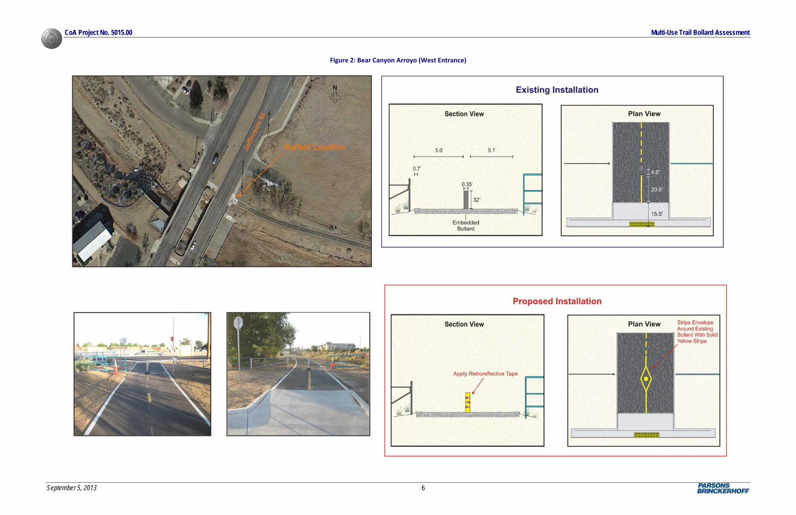
Striping an envelope around the approach to the post is recommended as shown below, to guide users around the object.
Source: AASHTO Guide for the Development of Bicycle Facilities, 2012 (Fourth Edition):
One strategy is to use flexible delineators, which may reduce unauthorized vehicle access without causing the injuries that are common with rigid bollards.
Bollards should be installed in locations where vehicles cannot easily bypass the bollard. Use of one bollard in the center of the path is preferred. When more than one post is used, an odd number of posts spaced at 6 feet is desirable. However, two posts are not recommended, as they direct opposing path users towards the middle, creating conflicts and the possibility of a head‐on collision. Wider spacing can allow entry to motor vehicles, while narrower spacing might prevent entry by adult tricycles, wheelchairs users, and bicycles with trailers.
Bollards should be set back from the roadway a minimum of 30 feet. Bollards set back from the intersection allow path users to navigate around the bollard before approaching the roadway.
Hardware installed in the ground to hold a bollard or post should be flush with the surface to avoid creating an additional obstacle.
Lockable, removable (or reclining) bollards allow entrance by authorized vehicles.
3. CITY OF ALBUQUERQUE BOLLARD INSTALLATIONS
The City of Albuquerque has installed bollards at numerous locations throughout the City’s trail system to control vehicular access on trails. Currently, standards or recommended practices to ensure consistent application are not fully established by the City of Albuquerque to govern the design and installation of trail bollards. The only City Standard Drawing established for bollard installation pertains to an installation for access to a drainage facility (see Appendix A). As part of this assessment, the City

CoA Project No. 5015.00 Multi-Use Trail Bollard Assessment
September 5, 2013 4
of Albuquerque requested that bollards at the following locations be reviewed and compared to AASHTO design guidelines:
Bear Canyon Arroyo Bridge (East Entrance), at the north end of Brentwood Lane (Figure 1)
Bear Canyon Arroyo Bridge (West Entrance), adjacent to the east side of Jefferson Street, north of Balloon Park Road (Figure 2)
Bear Canyon Arroyo Trail, adjacent to the west side of Jefferson Street, north of Balloon Park Road (Figure 3)
Gail Ryba Bridge (East Entrance), which crosses over the Rio Grande, adjacent to the Bosque Trail (Figure 4)
It should be noted that during the development of this assessment, changes were made to the bollard installations at the Bear Canyon Arroyo Bridge (East Entrance) and at the Bear Canyon Arroyo Bridge (West Entrance). For the purpose of this assessment, only the new installations were documented and evaluated as compared to AASHTO design guidelines. Table 1 summarizes the relevant design criteria for the each of the installations and indicates if the criteria meet or exceed AASHTO criteria.
Table 1: Multi‐Use Trail Design Criteria Summary
Retroreflectorized Material
Appropriate Object Markers ‐ ‐
ADA Accessible
(3 feet)
Clear Width
(5 feet)
Height
(40 inches)
Width
(4 inches)
One Bollard in Center
Odd Number of Posts with 6
foot Spacing‐ ‐
‐
‐ Criteria Met
‐ Criteria Not Met
Removable Bollards for Access
Flush Mounting Hardware
Permit Passage
Bollard Dimensions
Placement
Flexible Delineators
Setback(30 foot)minimum
Visibility
Gail Ryba Bridge
(East Entrance)
Adequate Sight Distance
Striped Envelope
Bear Canyon Arroyo Trail
(West Jefferson)
Bear Canyon Arroyo Bridge
(East Entrance)
Bear Canyon Arroyo Bridge
(West Entrance)

CoA Project No. 5015.00 Multi-Use Trail Bollard Assessment
September 5, 2013 5
Figure 1: Bear Canyon Arroyo (East Entrance)
CoA Project No. 5015.00 Multi-Use Trail Bollard Assessment
September 5, 2013 6
Figure 2: Bear Canyon Arroyo (West Entrance)

CoA Project No. 5015.00 Multi-Use Trail Bollard Assessment
September 5, 2013 7
Figure 3: Bear Canyon Arroyo Trail

CoA Project No. 5015.00 Multi-Use Trail Bollard Assessment
September 5, 2013 8
Figure 4: Gail Ryba Bridge

CoA Project No. 5015.00 Multi-Use Trail Bollard Assessment
September 5, 2013 9
The evaluation findings show that the bollard installations reviewed are not in compliance with AASHTO and MUTCD recommendations. In conjunction with a cursory review of additional locations, the following issues are consistent throughout the City of Albuquerque:
Bollards are rarely retroreflectorized or emblazoned with retroreflectorized tape.
Bollards are not 40 inches in height and were always much shorter.
Striping is inconsistent between sites and even within a given trail segment.
Bollard placement (number and spacing) is inconsistent throughout the City.
Bollards are often placed too close to the roadway, frequently at the back of the entrance ramp to the trail.
The proposed modifications to the existing installations maintain existing equipment and enhance conditions with retroreflective paint and tape and optimization of bollard placement. Retractable, 40‐inch bollards were not specified unless a new bollard was required.
4. NATIONAL GUIDANCE
Since national standards governing the placement of bollards on multi‐use trails do not currently exist, different agencies, committees and coalitions have developed best practices or suggested guidance for bollard types, placement, and locations. The common thought is that bollards should be utilized to increase trail safety by providing separation between motorized vehicles and trail users. A trail entry point should provide safe access to users and keep unauthorized vehicles out.
The following are a summary of best practices and guidelines, including a summary of recommended revisions to the MUTCD (California), Section 9C‐101, for the implementation of bollards on multi‐use trails developed in California by the City of Sacramento and California Department of Transportation:
The first steps to control entry at a trail approach should be to install signs that state vehicle entry is prohibited, and to design the entry to discourage vehicle access.
Barriers should be placed out of the path of travel. Place bollards on the centerline or lane line of a trail.
Bollards should be permanently reflective for nighttime visibility and coated with a bright color for daytime visibility.
Bollards should be placed so that there is sufficient sight distance to allow users to adjust speed.
Bollards should permit passage, without dismounting, for adult tricycles, bicycles towing trailers, and tandem bicycles. Five feet of clearance should be measured face to face and not center to center.
o When placed off the pavement, bollards should be placed a minimum of 2‐feet from the edge of the trail or outer lane line.
Fold down and sleeve bollards should not be used on trails because when they are not in use, they are a hazard to users.
o If removable bollards are used, the foundation shall be flush with the surface.
Use special advance warning signs or pavement markings where sight distance is a concern.
Develop a separate access for authorized vehicles when warranted on shared facilities.

CoA Project No. 5015.00 Multi-Use Trail Bollard Assessment
September 5, 2013 10
These guidelines are largely consistent with other agency practices and recommendations. A summary of agency and organization guidelines and standard drawings are included in Appendix B.
5. SUMMARY AND RECOMMENDATIONS
The Albuquerque metropolitan area has more than 175 miles of paved multi‐use trails. While bollards are commonly used on these facilities, the City of Albuquerque does not have established standards defining the appropriate installation of bollards on a multi‐use trail and the applications are inconsistent. AASHTO together with the MUTCD, has developed recommended criteria for the installation of bollards on multi‐use trails, which are not design standards, but have been established as best practices.
The goal of bollards should be to balance the need to discourage unauthorized motorized vehicle access on a trail with the need to provide the trail users a facility without unnecessary obstructions. Therefore, developing a series of best practices for the installation of bollards on the City of Albuquerque trail system is critical for the purpose of not only providing consistency within the trail system, but also establishing a level of expectancy with the trail users that will result in less confusion and improvements in accessibility for all types of users.
Following is a list of best practices that should be consistent when installing bollards at any trail facility by the City of Albuquerque (Figure 5):
Only apply bollards if the need is demonstrated, or if the trail entrance cannot be designed or modified to discourage use by unauthorized motor vehicles. Bollard use should be reserved for problematic locations.
o Bollards should not be installed on trail facilities that parallel a roadway unless it is identified as a problematic location.
o Bollards should be considered along obscured facilities that are not readily visible and at other problematic locations.
All bollards should be made of a retroreflectorized material or have retroreflectorized tape affixed to them for easy visibility from both approaches to the bollard.
o Where possible, retractable bollards should be implemented. Appropriate usage ensures that the bollards will remain in place and cannot be removed from the site and when retracted, the bollard will not be a hazard.
Bollards should be 40 inches in height (minimum) and 4 inches (minimum) in diameter to ensure visibility.
In most instances, a single bollard should be placed at the centerline of the trail, where adequate sight distance is available.
o Two bollards should not be used as they typically will be placed in the center of the travel way for each travel direction.
o If it is necessary to restrict access adjacent to the multi‐use trail to restrict motorized traffic, bollards should be placed a minimum of 2‐feet off of the edge of the trail.
A minimum clear width of 5 feet should be provided between the edge of trail and the bollard.

CoA Project No. 5015.00 Multi-Use Trail Bollard Assessment
September 5, 2013 11
A striped envelope (4 inch, retroreflective yellow) should be striped around the bollard to provide guidance to divert users around the bollard. A striped yellow centerline should also be provided along the trail for 25‐feet on either side of the bollard.
Bollards should be set back 30‐feet from the roadway to separate the conflict point for users between the roadway and bollards, or as far back as is practical based on site conditions.
Figure 5: Recommended Practice for Bollard Placement
These recommendations are consistent with a draft policy being developed by the Greater Albuquerque Recreational Trails Committee (GARTC) (Appendix C) and current practices of the City of Albuquerque Parks and Recreation Department (coordination meeting held July 22, 2013). Standards to ensure consistent application should be implemented by all departments of the City of Albuquerque. Every trail and entrance are unique and special consideration will need to be given to each site to determine how best to place bollards, if the need for bollards is demonstrated.

September 5, 2013
Appendices

September 5, 2013
Appendix A: City of Albuquerque Standard Detail


September 5, 2013
Appendix B: Agency Bollard Standard Details

AmericanAssociationofStateHighwayTransportationOfficials(AASHTO)
GuidetoBicycleFacilities,4thEdition


BicyclingInfo.org
DesignDetails(web)

Home > Engineer Bicycle Facilities > Shared Use Paths > Design Details
Design Details
Width and clearance
Ten feet or 3 meters is the recommended minimum width for a two-way, shared use path on a separate right of way. Other critical measurements include:
8 feet (2.4m) may be used where bicycle traffic is expected to be low at all times, pedestrian use is only occasional, sightlines are good, passing opportunities are provided, and maintenance vehicles will not destroy the edge of the trail.
•
12 feet is recommended where substantial use by bicycles, joggers, skaters, and pedestrians is expected, and where grades are steep (see later).
•
2 feet of graded area should be maintained adjacent to both sides of the path.•3 feet of clear distance should be maintained between the edge of the trail and trees, poles, walls, fences, guardrails or other lateral obstructions.
•
8 feet of vertical clearance to obstructions should be maintained; rising to 10 feet in tunnels and where maintenance and emergency vehicles must operate.
•
Design speed, horizontal and vertical alignment
The design of a shared use path should take into account the likely speed of users, the ability of bicyclists to turn corners without falling over, skidding, or hitting their pedal on the ground as they lean over. The AASHTO Guide for the Design of Bicycle Facilities has a number of tables, and equations to help designers meet the tolerances of a bicyclist based on the following key numbers:
20 miles per hour (30 km/h ) is the minimum design speed to use in designing a trail•30 miles per hour (50 km/h) should be used where downgrades exceed 4 percent•15 miles per hour (25 km/h) should be used on unpaved paths where bicyclists tend to ride more slowly (and cannot stop as fast without skidding or sliding on a loose surface)
•
The result is a series of recommended desirable minimum curve radii for corners that should be safe for bicyclists.
Page 1 of 6bicyclinginfo.org: Design Details
9/4/2013http://www.bicyclinginfo.org/engineering/paths-details.cfm

Lighting
Shared use paths in urban and suburban areas often serve travel needs both day and night, for example commuter routes and trails accessing college campuses. Fixed source lighting improves visibility along trails and at intersections, and is critical for lighting tunnels and underpasses. The AASHTO guide recommends using average maintained illumination levels of between 5 and 22 lux, and the Florida DOT recommends 25 as the average initial lux. Also, there needs to be a periodic monitoring of the lights and a maintenance program.
Preventing motor vehicle use of paths
In some locations, shared use paths may be mistaken for motor vehicle roads or may suffer from illegal or unauthorized motorized use. At intersections with roadways, therefore, the path should be clearly signed, marked and/or designed to discourage or prevent unauthorized motorized access. A variety of alternatives exist to achieve this:
bollards. Probably the most common device is the bollard, often lockable, collapsible or removable to allow for authorized access to the trail. Great care should be used in locating the bollard to ensure that they are visible, allow trail users through, and are not placed so as to channel both directions of trail users towards the same point in the trail. If bollards are to be used, they should be retro-reflective, brightly colored, and have pavement markings around them. On a ten foot trail, one bollard should be used in the center of the trail. If more than one bollard is necessary, there should be five feet between them.
a.
splitting the trail in two. Many manuals suggest the option of splitting a ten foot trail into two five foot approaches to an intersection, with a planted triangle between them. This may increase maintenance costs.
b.
medians. The Florida DOT manual notes that "curbing with tight radii leading up to the roadway can often prevent motorists from attempting to enter the path. Medians should be set back from the intersection 25 feet (8m) to allow bicyclists to exit the roadway fully before navigating the reduced pathway width."
c.
Signing and marking
While fewer signs may be needed on paths compared to on-street facilities, adequate signing and marking are essential on shared use paths, just as they are on streets and highways. Trail users need to know about potential conflicts, regulatory information, destinations, cross streets etc. The Manual on Uniform Traffic Control Devices (MUTCD) provides some minimum traffic control measures that should be applied and a range of options.
Page 5 of 6bicyclinginfo.org: Design Details
9/4/2013http://www.bicyclinginfo.org/engineering/paths-details.cfm

This site is funded by the U.S. Department of Transportation Federal Highway Administration and maintained by the Pedestrian and Bicycle Information Center within the University of North Carolina Highway Safety Research Center. Please read our Usage
Guidelines
Striping: a yellow center line stripe is recommended where trails are busy, where sight distances are restricted, and on some unlit trails where night time riding is expected. The line should be dashed when adequate passing sight distance exists, and solid when no passing is recommended.
A solid white line may be used to separate pedestrians from bicycle/blading traffic, and solid white edge stripes may also be useful where nighttime riding is expected.
Warning signs: a range of warning signs can be used to inform users that recommended design criteria cannot be met, for example curve radii or grades or where unexpected conditions may exist.
Informational signs: trail users need to know where they are, where they are going, what cross streets they are crossing, how far destinations are away, and what services are available close to the trail. The MUTCD has information on the appropriate signs to use in these instances. Although not in the MUTCD, many trails post signs encouraging uniform trail user etiquette (e.g. "give audible signal when passing" or which type of trail user has the right-of-way).
Intersection markings and signs: pavement marking and signs at intersections should channel users to cross at clearly defined locations and indicate that crossing traffic is to be expected. Similar devices to those used on roadways (STOP and YIELD signs, stop bars etc) should be used on trails as appropriate.
The AASHTO Guide notes that in addition to traditional warning signs in advance of intersections, motorists can be alerted to the presence of a trail crossing through flashing warning lights, zebra-style or colored pavement crosswalks, raised crosswalks, signals, and neck-downs/curb-bulbs. However, some devices such as flashing warning lights are expensive to install and maintain and should be kept to a minimum.
Page 6 of 6bicyclinginfo.org: Design Details
9/4/2013http://www.bicyclinginfo.org/engineering/paths-details.cfm

Caltrans
CaltransHighwayDesignManualChapter1000

HIGHWAY DESIGN MANUAL 1000-1 May 7, 2012
CHAPTER 1000 BICYCLE TRANSPORTATION
DESIGN
Topic 1001 - Introduction
Index 1001.1 – Bicycle Transportation
The needs of non motorized transportation are an essential part of all highway projects. Mobility for all travel modes is recognized as an integral element of the transportation system. Therefore, the guidance provided in this manual complies with Deputy Directive 64-Revision #1: Complete Streets: Integrating the Transportation System. See AASHTO, “Guide For The Development Of Bicycle Facilities”.
Design guidance for Class I bikeways (bike paths), Class III bikeways (bike routes) and Trails are provided in this chapter. Design guidance that addresses the mobility needs of bicyclists on all roads as well as on Class II bikeways (bike lanes) is distributed throughout this manual where appropriate.
See Topic 116 for guidance regarding bikes on freeways.
1001.2 Streets and Highways Code References
The Streets and Highways Code Section 890.4 defines a “bikeway” as a facility that is provided primarily for bicycle travel. Following are other related definitions, found in Chapter 8 Nonmotorized Transportation, from the Streets and Highway Code:
(a) Section 887 -- Definition of nonmotorized facility.
(b) Section 887.6 -- Agreements with local agencies to construct and maintain nonmotorized facilities.
(c) Section 887.8 -- Payment for construction and maintenance of nonmotorized facilities approximately paralleling State highways.
(d) Section 888 -- Severance of existing major non motorized route by freeway construction.
(e) Section 888.2 -- Incorporation of non motorized facilities in the design of freeways.
(f) Section 888.4 -- Requires Caltrans to budget not less than $360,000 annually for non motorized facilities used in conjunction with the State highway system.
(g) Section 890.4 -- Class I, II, and III bikeway definitions.
(h) Section 890.6 - 890.8 -- Caltrans and local agencies to develop design criteria and symbols for signs, markers, and traffic control devices for bikeways and roadways where bicycle travel is permitted.
(i) Section 891 -- Local agencies must comply with design criteria and uniform symbols.
(j) Section 892 -- Use of abandoned right-of-way as a nonmotorized facility.
1001.3 Vehicle Code References
(a) Section 21200 -- Bicyclist's rights and responsibilities for traveling on highways.
(b) Section 21202 -- Bicyclist's position on roadways when traveling slower than the normal traffic speed.
(c) Section 21206 -- Allows local agencies to regulate operation of bicycles on pedestrian or bicycle facilities.
(d) Section 21207 -- Allows local agencies to establish bike lanes on non-State highways.
(e) Section 21207.5 -- Prohibits motorized bicycles on bike paths or bike lanes.
(f) Section 21208 -- Specifies permitted movements by bicyclists from bike lanes.
(g) Section 21209 -- Specifies permitted movements by vehicles in bike lanes.
(h) Section 21210 -- Prohibits bicycle parking on sidewalks unless pedestrians have an adequate path.
(i) Section 21211 -- Prohibits impeding or obstruction of bicyclists on bike paths.
(j) Section 21400 – Adopt rules and regulations for signs, markings, and traffic control devices for roadways user.

HIGHWAY DESIGN MANUAL 1000-9 May 7, 2012
with adequate stopping sight distances. The
minimum stopping sight distance based on design speed shall be 125 feet for 20 miles per hour, 175 feet for 25 miles per hour and 230 feet for 30 miles per hour. The distance required to bring a bicycle to a full controlled stop is a function of the bicyclist’s perception and brake reaction time, the initial speed of the bicycle, the coefficient of friction between the tires and the pavement, and the braking ability of the bicycle.
Stopping sight distance is measured from a bicyclist’s eyes, which are assumed to be 4 ½ feet above the pavement surface to an object ½-foot high on the pavement surface.
(11) Length of Crest Vertical Curves. Figure 1003.1C indicates the minimum lengths of crest vertical curves for varying design speeds.
(12) Lateral Clearance on Horizontal Curves. Figure 1003.1D indicates the minimum clearances to line of sight obstructions, m, for horizontal curves. It is assumed that the bicyclist’s eyes are 4 ½ feet above the pavement surface to an object ½-foot high on the pavement surface.
Bicyclists frequently ride abreast of each other on bicycle paths, and on narrow bicycle paths, bicyclists have a tendency to ride near the middle of the path. For these reasons, lateral clearances on horizontal curves should be calculated based on the sum of the stopping sight distances for bicyclists traveling in opposite directions around the curve. Where this is not possible or feasible, the following or combination thereof should be provided: (a) the path through the curve should be widened to a minimum paved width of 14 feet; and (b) a yellow center line curve warning sign and advisory speed limit signs should be installed.
(13) Grades. Bike path grades must meet DIB 82. The maximum grade rate recommended for bike paths should be 5 percent. Sustained grades should be limited to 2 percent.
(14) Pavement Structure. The pavement material and structure of a bike path should be designed in the same manner as a highway, with a recommendation from the District Materials Branch. It is important to construct and
maintain a smooth, well drained, all-weather riding surface with skid resistant qualities, free of vegetation growth. Principal loads will normally be from maintenance and emergency vehicles.
(15) Drainage. For proper drainage, the surface of a bike path should have a minimum cross slope of 1 percent to reduce ponding and maximum of 2 percent Per DIB 82. Sloping of the traveled way in one direction usually simplifies longitudinal drainage design and surface construction, and accordingly is the preferred practice. However, the unpaved shoulders slope away from the path at 2 percent. Ordinarily, surface drainage from the path will be adequately dissipated as it flows down the gently sloping shoulder. However, when a bike path is constructed on the side of a hill, a drainage ditch of suitable dimensions may be necessary on the uphill side to intercept the hillside drainage. Where necessary, catch basins with drains should be provided to carry intercepted water across the path. Such ditches should be designed in such a way that no undue obstacle is presented to bicyclists.
Culverts or bridges are necessary where a bike path crosses a drainage channel.
(16) Entry Control for Bicycle Paths. Obstacle posts and gates are fixed objects and placement within the bicycle path traveled way can cause them to be an obstruction to bicyclists. Obstacles such as posts or gates may be considered only when other measures have failed to stop unauthorized motor vehicle entry. Also, these obstacles may be considered only where safety and other issues posed by actual unauthorized vehicle entry are more serious than the safety and access issues posed to bicyclists, pedestrians and other authorized path users by the obstacles.
The 3-step approach to prevent unauthorized vehicle entry is:
(a) Post signs identifying the entry as a bicycle path with regulatory signs prohibiting motor vehicle entry where roads and bicycle paths cross and at other path entry points.
(b) Design the path entry so it does not look like a vehicle access and makes intentional

1000-10 HIGHWAY DESIGN MANUAL May 7, 2012 access by unauthorized users more difficult.
Dividing a path into two one-way paths prior to the intersection, separated by low plantings or other features not conducive to motor vehicle use, can discourage motorist from entering and reduce driver error.
(c) Assess whether signing and path entry design prevents or minimizes unauthorized entry to tolerable levels. If there are documented issues caused by unauthorized motor vehicle entry, and other methods have proven ineffective, assess whether the issues posed by unauthorized vehicle entry exceed the crash risks and access issues posed by obstacles.
If the decision is made to add bollards, plantings or similar obstacles, they should be:
• Yielding to minimize injury to bicyclists and pedestrians who may strike them.
• Removable or moveable (such as gates) for emergency and maintenance access must leave a flush surface when removed.
• Reflectorized for nighttime visibility and painted, coated, or manufactured of material in a bright color to enhanced daytime visibility.
• Illuminated when necessary.
• Spaced to leave a minimum of 5 feet of clearance of paved area between obstacles (measured from face of obstacle to face of adjacent obstacle). Symmetrically about the center line of the path.
• Positioned so an even number of bicycle travel lanes are created, with a minimum of two paths. Odd number of openings increases the risk of head-on collisions if traffic in both directions tries to use the same opening.
• Placed so additional, non-centerline/lane line posts are located a minimum of 2 feet from the edge of pavement.
• Delineated as shown in California MUTCD Figure 9C-2.
• Provide special advance warning signs or painted pavement markings if sight distance is limited.
• Placed 10 to 30 feet back from an intersection, and 5 to 10 feet from a bridge, so bicyclists approach the obstacle straight-on and maintenance vehicles can pull off the road.
• Placed beyond the clear zone on the crossing highway, otherwise breakaway.
When physical obstacles are needed to control unauthorized vehicle access, a single non-removable, flexible, post on the path centerline with a separate gate for emergency/maintenance vehicle access next to the path, is preferred. The gate should swinging away from the path,
Fold-down obstacle posts or bollards shall not be used within the paved area of bicycle paths. They are often left in the folded down position, which presents a crash hazard to bicyclists and pedestrians. When vehicles drive across fold-down obstacles, they can be broken from their hinges, leaving twisted and jagged obstructions that project a few inches from the path surface.
Obstacle posts or gates must not be used to force bicyclists to slow down, stop or dismount. Treatments used to reduce vehicle speeds may be used where it is desirable to reduce bicycle speeds.
For obstacle post visibility marking, and pavement markings, see the California MUTCD, Section 9C.101(CA).
(17) Lighting. Fixed-source lighting raises awareness of conflicts along paths and at intersections. In addition, lighting allows the bicyclist to see the bicycle path direction, surface conditions, and obstacles. Lighting for bicycle paths is important and should be considered where nighttime use is not prohibited, in sag curves (see Index 201.5), at intersections, at locations where nighttime security could be a problem, and where obstacles deter unauthorized vehicle entry to bicycle paths. See Index 1003.1(16). Daytime lighting should also be considered through underpasses or tunnels.

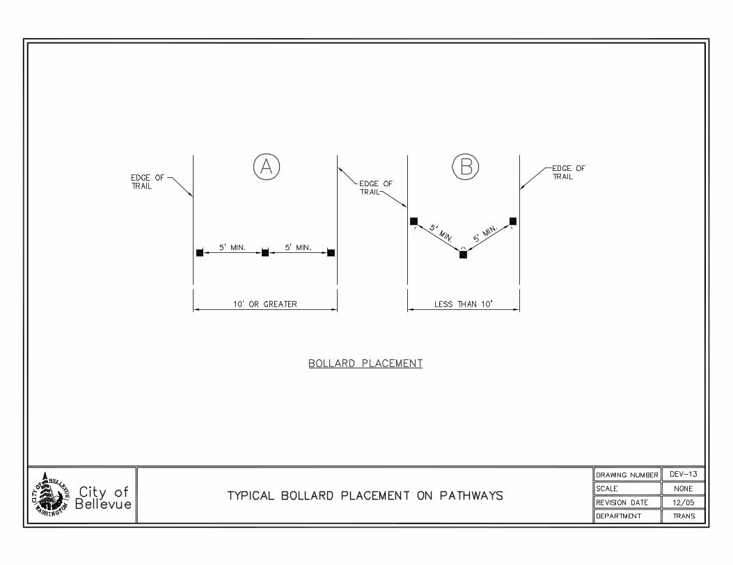
CityofBellevue(WA)
StandardDetails


CityofFremont(CA)
RetractableBollardStandardDetail

PARK STANDARD DETAILS
RETRACTABLE BOLLARD
1 OF 1 PSD SF-2 05/06/0211 RER EL/TB N.T.S. PSD SF-2.DWG
FINISH GRADE
ADJACENT
PAVING
CONCRETE FOOTING
SEE SPECIFICATIONS
CONNECT SOLID DRAIN PIPE TO
STORM DRAIN. SEE GRADING
AND DRAINAGE PLAN.
FLAT TOP
5" DIAMETER
COMPACTED SUBGRADE
NOTES:
1. COLOR: BLACK; SEE SPECIFICATIONS
2. SUBMIT COLOR SAMPLE TO CITY LANDSCAPE ARCHITECT FOR APPROVAL PRIOR TO ORDERING.
3. INSTALL PER MANUFACTURER'S SPECIFICATIONS.
4. WHERE STORM DRAIN IS NOT AVAILABLE INSTALL DRAIN SUMP WITH CITY APPROVAL. SUMP TO BE CLASS II
WASHED DRAIN ROCK WRAPPED IN MIRAFI 140 FABRIC, OR APPROVED EQUAL. SEE PSD SF-4.
KEY HOLE
GAS JACK, TYP.
LOCK BAR. TYP.
BOLLARD CASING -
INSTALL PER LAYOUT PLAN
4" SOLID DRAIN PIPE
26
1
/2
"
RETRACTABLE
BOLLARD
10"10"
ACCEPTABLE MANUFACTURER, OR APPROVED EQUAL:
URBACO
CHATEAUNEUF SEMI-AUTOMATIC RETRACTABLE BOLLARD
MODEL #9240, 26" HEIGHT ABOVE GROUND LEVEL
PHONE #: (888) 987-2220
12'
9"
COVER
LOCK
PLAN VIEW
WHEN IN CONCRETE, ADD
DEEP JOINT TO CONTROL
CRACKING
December 13, 2011
2011-65

CityofOakland(CA)
BollardPlacementandMarkingsStandardDrawings


FederalHighwayAdministration(FHWA)–TrailProgram
Bollards,Gates,andotherBarriers(web)
About Programs Resources Briefing Room Contact Search FHWA
FHWA RTP Contact
Christopher Douwes Trails and Enhancements Program Manager Federal Highway Administration FHWA HEPH-10 Rm E74-474 1200 New Jersey Ave SE Washington DC 20590-0001 Phone: 202-366-5013 Fax: 202-366-3409
State RTP Contacts
Contact your State RTP Administrator to ask about policies and funding in your State.
See also: Federal Agency Contacts
Overview
Legislation
Guidance
Accessibility Guidance
•
Financial Management
•
State Practices•
Funding
Publications
Meetings & Events
Resources
RTP & TE Update
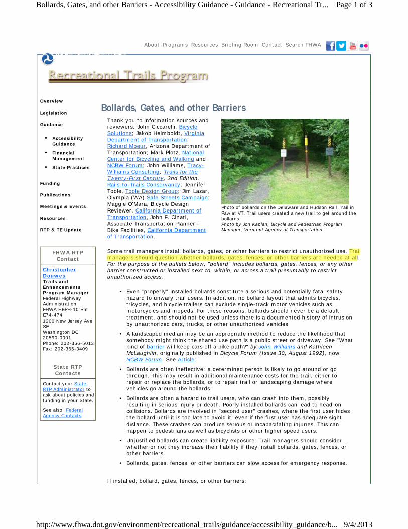
Photo of bollards on the Delaware and Hudson Rail Trail in Pawlet VT. Trail users created a new trail to get around the bollards. Photo by Jon Kaplan, Bicycle and Pedestrian Program Manager, Vermont Agency of Transportation.
Bollards, Gates, and other BarriersThank you to information sources and reviewers: John Ciccarelli, Bicycle Solutions; Jakob Helmboldt, Virginia Department of Transportation; Richard Moeur, Arizona Department of Transportation; Mark Plotz, National Center for Bicycling and Walking and NCBW Forum; John Williams, Tracy-Williams Consulting; Trails for the Twenty-First Century, 2nd Edition, Rails-to-Trails Conservancy; Jennifer Toole, Toole Design Group; Jim Lazar, Olympia (WA) Safe Streets Campaign; Maggie O'Mara, Bicycle Design Reviewer, California Department of Transportation, John F. Cinatl, Associate Transportation Planner - Bike Facilities, California Department of Transportation.
Some trail managers install bollards, gates, or other barriers to restrict unauthorized use. Trail managers should question whether bollards, gates, fences, or other barriers are needed at all. For the purpose of the bullets below, "bollard" includes bollards, gates, fences, or any other barrier constructed or installed next to, within, or across a trail presumably to restrict unauthorized access.
Even "properly" installed bollards constitute a serious and potentially fatal safety hazard to unwary trail users. In addition, no bollard layout that admits bicycles, tricycles, and bicycle trailers can exclude single-track motor vehicles such as motorcycles and mopeds. For these reasons, bollards should never be a default treatment, and should not be used unless there is a documented history of intrusion by unauthorized cars, trucks, or other unauthorized vehicles.
•
A landscaped median may be an appropriate method to reduce the likelihood that somebody might think the shared use path is a public street or driveway. See "What kind of barrier will keep cars off a bike path?" by John Williams and Kathleen McLaughlin, originally published in Bicycle Forum (Issue 30, August 1992), now NCBW Forum. See Article.
•
Bollards are often ineffective: a determined person is likely to go around or go through. This may result in additional maintenance costs for the trail, either to repair or replace the bollards, or to repair trail or landscaping damage where vehicles go around the bollards.
•
Bollards are often a hazard to trail users, who can crash into them, possibly resulting in serious injury or death. Poorly installed bollards can lead to head-on collisions. Bollards are involved in "second user" crashes, where the first user hides the bollard until it is too late to avoid it, even if the first user has adequate sight distance. These crashes can produce serious or incapacitating injuries. This can happen to pedestrians as well as bicyclists or other higher speed users.
•
Unjustified bollards can create liability exposure. Trail managers should consider whether or not they increase their liability if they install bollards, gates, fences, or other barriers.
•
Bollards, gates, fences, or other barriers can slow access for emergency response.•
If installed, bollard, gates, fences, or other barriers:
Page 1 of 3Bollards, Gates, and other Barriers - Accessibility Guidance - Guidance - Recreational Tr...
9/4/2013http://www.fhwa.dot.gov/environment/recreational_trails/guidance/accessibility_guidance/b...

Must not restrict access for people with disabilities (ABA, Rehabilitation Act, and ADA: cited above).
•
Must be easily visible, especially in low light conditions. Section 9C.03 of the Manual on Uniform Traffic Control Devices (MUTCD) requires retroreflectorization of any obstruction in the traveled way of a shared-use path. This includes posts along the edge of a path (within a path's "shoulder"). In addition, MUTCD Figure 9C-2 defines a diamond-shaped marking that should be used around bollards or other obstructions within a path.
•
Should have sufficient sight distance to allow users to adjust speed. This is especially important on paths that have traffic calming features such as curves or landscaping near the bollards. Insufficient sight distance increases the likelihood that bollards will be dangerous hazards.
•
Should permit passage, without dismounting, for adult tricycles, bicycles towing trailers, and tandem bicycles. All users legally permitted to use the facility should be accommodated; failure to do so increases the likelihood that the bollards will be dangerous hazards.
•
According to Trails for the Twenty-First Century, 2nd Edition (April 2001), published by the Rails-to-Trails Conservancy:
If you determine that a traffic barrier is necessary, ensure that barriers are well marked and visible to bicyclists, day or night... Bollards must be at least 3 feet tall and should be placed at least 10 feet from the intersection. This will allow trail users to cross the intersection before negotiating the barrier posts...
One bollard is generally sufficient to indicate that a path is not open to motorized vehicles. The post should be placed in the center of the trail tread. Where more than one post is necessary, a 5-foot spacing is used to permit passage of bicycle trailers, adult tricycles, and wheelchairs. Always use one or three bollards, never two. Two bollards, both placed in the paved portion of the trail, will channel trail users into the center of the trail, causing possible head-on collisions. Bollards should be designed to be removable or hinged to permit entrance by emergency and service vehicles... (Pages 85-86).
Additional Notes:
Spacing between bollards should permit passage of bicycle trailers and adult tricycles without dismounting, and manual and motorized wheelchairs. A "5-foot spacing" means 5-foot gaps between bollards, not a 5-foot center-to-center placement.
•
Bollards should be designed to be knock-down, removable, or hinged to permit entrance by emergency and service vehicles. A knocked-down bollard must be reinstalled or removed immediately to avoid having an additional safety hazard.
•
Hardware installed in the ground to hold bollard or posts must be flush with the surface to avoid having an additional safety hazard.
•
Bollards, gates, fences, or other barriers outside the trail tread (on each side) may be acceptable if there is sufficient clear trail tread to avoid head-on collisions and to ensure accessibility. But the purpose of the bollards, gates, fences, or other barriers should be questioned.
•
Additional Resources:
Presentation: Bicycle Path Entry Control. (Ed Cox, Bicycle and Pedestrian Coordinator, City of Sacramento, CA and Maggie O'Mara, Senior Transportation Engineer, California Department of Transportation) This presentation discusses methods to control entry to shared use paths. It considers issues related to bollards, gates, and other barriers. It looks at examples and discusses what works well and what doesn't. Disclaimer: This presentation is provided in the interest of information exchange,
•
Page 2 of 3Bollards, Gates, and other Barriers - Accessibility Guidance - Guidance - Recreational Tr...
9/4/2013http://www.fhwa.dot.gov/environment/recreational_trails/guidance/accessibility_guidance/b...

Privacy Policy | Freedom of Information Act (FOIA) | Accessibility | Web Policies & Notices | No Fear Act | Report Waste, Fraud and Abuse U.S. DOT Home | USA.gov | WhiteHouse.gov Federal Highway Administration | 1200 New Jersey Avenue, SE | Washington, DC 20590 | 202-366-4000
and reflects the views of the authors. Providing this resource does not necessarily represent endorsement by the U.S. Department of Transportation.
Page 3 of 3Bollards, Gates, and other Barriers - Accessibility Guidance - Guidance - Recreational Tr...
9/4/2013http://www.fhwa.dot.gov/environment/recreational_trails/guidance/accessibility_guidance/b...

MaricopaAssociationofGovernments(AZ)
StandardDetail


MinnesotaDepartmentofTransportation(Mn/DOT)
Mn/DOTBikewayFacilityDesignManual

Chap
ter 5
Share
d-Use
Path
s
Mn/DOT Bikeway Facility Design Manual 123
Chapter 5: Shared-Use Paths
5-1.0 IntroductionThis chapter provides guidelines for design of bicycle transportation facilities that are
separated from the roadway. In most cases, a path separated from the roadway may be
used by bicyclists, pedestrians, roller skaters, and individuals in wheel chairs, as well as
other users, and the path must be designed for shared use. This manual does not provide
guidance on design or construction of recreational off-road mountain biking paths. The 2006
Department of Natural Resources, Trail Planning Design, and Development Guidelines,
provides detailed guidance on shared use paved trails, natural surface trails, winter use trails
and bikeways.
5-1.1 Types of Off-Roadway Bicycle FacilitiesIn addition to shared-use paths, several other types of off-roadway facilities may meet the
needs of various users, as described below.
5-1.1.1 Shared-Use PathsShared-use path is a term adopted by the 1999 AASHTO Guide for the Development of
Bicycle Facilities in recognition that
paths are seldom, if ever, used
only by bicycles. As shown in
Figure 5-1, a shared-use path is
typically located on exclusive right-
of-way, with no fixed objects in the
pathway and minimal cross flow by
motor vehicles. Portions of a
shared-use path may be within the
road right-of-way but physically
separated from the roadway by a
barrier or landscaping. Users
typically include bicyclists, in-line
skaters, wheelchair users (both
non-motorized and motorized) and
pedestrians, including walkers,
runners, people with baby strollers
or dogs with people.
Shared-use paths are a valuable element of bicycle networks and serve both a transportation
and recreation function, providing route continuity for commuting and recreation trips, access
to destinations not otherwise available to bicyclists on the street and road system, and
access between buildings and other discontinuities in the street network. Where shared-use
paths have been added to the transportation network, they have proven to be significant
Figure 5-1:Example of typical shared-use path

5-4.3.3 Curb Ramp Design and ArrangementsUse curb ramps at every intersection between a shared-use path and a roadway. If the
approaching path is perpendicular to the curb, the width of the curb ramp should be at least as
wide as the average width of the shared-use path. If the path is parallel to the curb, the width of
the curb ramp should equal the path width or 2.7 m (9 ft), whichever is greater.
If a crossing or crosswalk is intended for bicyclists, the curb ramp or sloping pavement should be
flush with the street. The slope of the curb ramp shall be no greater than 8.3 percent (12:1), and
the slope of the curb ramp flares should be no greater than 10 percent (10:1).
Curb ramps shall include a 0.6 m (2.0 ft) wide strip of
detectable warnings at their base to ensure that path users
with vision impairments are aware of the intersection,
according to the Americans with Disabilities Act
Accessibility Guidelines (ADAAG). According to ADAAG
and Mn/DOT Standard Plate 7036, detectable warnings
should consist of raised truncated domes that meet the
following specifications:
● Bottom diameter 23 mm (0.9 in) to 36 mm
(1.4 in)● Top diameter 50 to 65 percent of base diameter
● Height of 5 mm (0.2 in)● Center-to-center spacing of 41 to 61 mm (1.6 to
2.4 in)● A color contrasting with adjacent pavement, either
light on dark or dark on light, which can help all
path users to locate the curb on the opposite corner
as well as provide visual cue of the truncated dome
strip.
Other detectable surfaces, such as aggregate and grooves,
are less detectable and less easily understood by people
with vision impairments. ADAAG specifies truncated domes
over rounded domes because they provide greater access
to people with mobility impairments.
5-4.3.4 Controlling Motor Vehicle AccessA good method of controlling access onto a path by motor
vehicles is to split the entry into two one-way sections of
path, each 1.5 m (5 ft) wide, separated by low
landscaping or other material. Emergency vehicles can
still enter if necessary by straddling the landscaping. In
most situations, this is preferable to bollards, chicanes, or
other methods.
154 Chapter 5: Shared-Use Paths
Mn/DOT Bikeway Facility Design Manual March 2007
Too many bollards inhibitpath access.
Example of swing-downbollard to allow emergencyand maintenance vehicleaccess
Figure 5-20:Bollards

March 2007 Mn/DOT Bikeway Facility Design Manual
Chapter 5: Shared-Use Paths 155
A bollard may also be used at the entrance to a bicycle path. See Figure 5-20. When used, a
single bollard may be installed in the
middle of the path to deny access to
motor vehicles. Removable or hinged
flexible bollards are recommended so
service vehicles can use the path.
When more than one bollard is used,
there should always be one in the center
of the path, and bollards on both edges,
1.5 m (5 ft) from the center bollard.
This spacing will accommodate any type
of bicycle or wheelchair.
Gates and other devices that require
path users to maneuver around objects
are strongly discouraged. See Figure
5-21.
5-4.3.5 One-Way Paths and Signalized IntersectionsOne-way paths have the advantage of increased visibility and safety at signalized intersections.
Where there are substantial numbers of right-turning motorists and through bicyclists, the one-
way path intersection design shown in Figure 5-22 should be considered. End the one-way path
20 to 30 m (65 to 100 ft) before the intersection and let bicyclists continue on a bicycle lane in
the roadway.
Figure 5-21:Gates across a bicycle path (not recommended)
< 30 m (100 ft)
path
< 20 m (65 ft)
LANE
BIKE
LANE
BIKE
> 1.5 m (> 5 ft)
Figure 5-22:One-Way Path Approaching Intersection

NewYorkCityDepartmentofParksandRecreation(NYCDPR)
NYCBicycleMasterPlan


OregonDepartmentofTransportation
BicycleandPedestrianDesignGuide(2011)


CHAPTER 7: SHARED USE PATHS
7-15OR E G O N BI C Y C L E A N D PE D E S T R I A N DE S I G N GU I D E
Preventing Motor-Vehicle AccessGeometric Design
The most effective way to discourage motor vehicle access to paths is to make it physically diffi cult to do so. One method branches the path into two narrower one-way paths just before it reaches the roadway, making it diffi cult for a motor vehicle to gain access to the path.
Figure 7-20: Path splits to prevent it appearing like a driveway
Another method is to create very tight curb returns to make it diffi cult for motorists to enter a path from the roadway.
17’ **
3’
2 :1
40’** 23’ req’d over RR tracks17’.4” over NHS Highways routes17.0’ over NHS (Non Highway Routes)16.0’ over non - NHS Routes
200’
17’
3’
2:1
5%
*
**
400’
17’
3’
FILL2:1
5%
FILL**
*
* not to scale
MONTHSTICKER YEARSTICKER
MONTHSTICKER YEARSTICKER
MONTHSTICKER YEARSTICKERMONTHSTICKER YEARSTICKER
Figure 7-19: Path overcrossings, various confi gurations
short curbradius
detectablewarning
Figure 7-21: Tight curb radii prevent motor vehicle access
BollardsBollards may be used to limit vehicle traffi c on paths. However, they are often hard to see, cyclists may not expect them and injuries result when cyclists hit them. Overuse of bollards is a serious hazard to bicyclists and may prevent path use by trailers, wheelchairs and other legitimate path users. In a group of riders, the riders in front block the visibility of those behind, setting up cyclists in the back of the pack for a crash.

7-16 OR E G O N BI C Y C L E A N D PE D E S T R I A N DE S I G N GU I D E
CHAPTER: 7 SHARED USE PATHS
Offset FencingPlacing railing or other barrier part way across a trail makes it possible for intended users to accesses the trail; maintenance vehicle operators are provided with keys to unlock the fences when they need access. The fences, like bollards, can be hazards to bicyclists and can restrict certain trail users from gaining access to the trail. They should be coated with retro-refl ective material and well-lit.
Detectable warning
Offset fencing must have reflective coating
Short curb radius
Offset must be sufficient for tandems and trailers
Figure 7-22: Offset gates prevent motor vehicle access
Offset fencing
Bollards should only be used when absolutely necessary. When used, they must be spaced wide enough (min. 5 feet) for easy passage by cyclists, bicycle trailers and adult tricycles as well as wheelchair users. A single bollard is preferred, as two may channelize bicyclists to the middle opening, with a potential for collisions. They should not be placed right at the intersection, but set back 20 feet or more, so users can concentrate on motor vehicle traffi c confl icts rather than on avoiding the bollard. They should be painted with bright, light colors for visibility, illuminated and/or retro-refl ectorized. A striped envelope around the bollard will direct path users away from the fi xed object hazard. Flexible delineators, that collapse when struck by a bicyclist, should be considered.
Bollards are overused and can cause injury
Split path entry eliminates need for bollards

WashingtonStateDepartmentofTransportation(WSDOT)
WSDOTDesignManualChapter1515
WSDOTStandardPlans

WSDOT Design Manual M 22-01.09 Page 1515-1 July 2012
Chapter 1515 Shared-Use Paths
1515.01 General 1515.02 References 1515.03 Definitions 1515.04 Shared-Use Path Design – The Basics 1515.05 Intersections and Crossings Design 1515.06 Grade Separation Structures 1515.07 Signing, Pavement Markings, and Illumination 1515.08 Restricted Use Controls 1515.09 Documentation
1515.01 General
Shared-use paths are designed for both transportation and recreation purposes and are used by pedestrians, bicyclists, skaters, equestrians, and other users. Some common locations for shared-use paths are along rivers, streams, ocean beachfronts, canals, utility rights of way, and abandoned railroad rights of way; within college campuses; and within and between parks as well as within existing roadway corridors. A common application is to use shared-use paths to close gaps in bicycle networks. There might also be situations where such facilities can be provided as part of planned developments. Where a shared-use path is designed to parallel a roadway, provide a separation between the path and the vehicular traveled way in accordance with this chapter.
As with any roadway project, shared-use path projects need to fit into the context of a multimodal community. Exhibits are provided throughout this chapter to illustrate possible design solutions, which should be treated with appropriate flexibility as long as doing so complies with corresponding laws, regulations, standards, and guidance. Engage various discipline experts, including landscape architects, soil and pavement engineers, maintenance staff, traffic control experts, ADA and bicycle coordinators, and others. Additionally, when designing such facilities, consider way-finding.
This chapter includes technical provisions for making shared-use paths accessible to persons with disabilities. Design shared-use paths and roadway crossings in consultation with your region’s ADA Coordinator, Bicycle Coordinator, and State Bicycle and Pedestrian Coordinator. For additional information on pedestrian and bicycle facilities, see Chapters 1510 and 1520, respectively.
1515.02 References
(1) Federal/State Laws and Codes Americans with Disabilities Act of 1990 (ADA)
ADA (28 CFR Part 35, as revised September 15, 2010)
23 CFR Part 652, Pedestrian and Bicycle Accommodations and Projects
49 CFR Part 27, Nondiscrimination on the Basis of Disability in Programs or Activities Receiving Federal Financial Assistance (Section 504 of the Rehabilitation Act of 1973 implementing regulations)
Shared-Use Paths Chapter 1515
Page 1515-18 WSDOT Design Manual M 22-01.09 July 2012
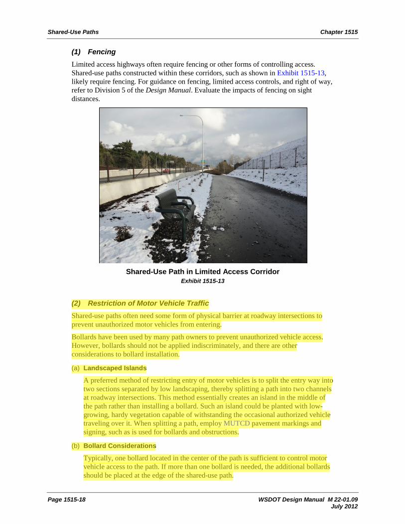
(1) Fencing Limited access highways often require fencing or other forms of controlling access. Shared-use paths constructed within these corridors, such as shown in Exhibit 1515-13, likely require fencing. For guidance on fencing, limited access controls, and right of way, refer to Division 5 of the Design Manual. Evaluate the impacts of fencing on sight distances.
Shared-Use Path in Limited Access Corridor Exhibit 1515-13
(2) Restriction of Motor Vehicle Traffic Shared-use paths often need some form of physical barrier at roadway intersections to prevent unauthorized motor vehicles from entering.
Bollards have been used by many path owners to prevent unauthorized vehicle access. However, bollards should not be applied indiscriminately, and there are other considerations to bollard installation.
(a) Landscaped Islands
A preferred method of restricting entry of motor vehicles is to split the entry way into two sections separated by low landscaping, thereby splitting a path into two channels at roadway intersections. This method essentially creates an island in the middle of the path rather than installing a bollard. Such an island could be planted with low-growing, hardy vegetation capable of withstanding the occasional authorized vehicle traveling over it. When splitting a path, employ MUTCD pavement markings and signing, such as is used for bollards and obstructions.
(b) Bollard Considerations
Typically, one bollard located in the center of the path is sufficient to control motor vehicle access to the path. If more than one bollard is needed, the additional bollards should be placed at the edge of the shared-use path.

Chapter 1515 Shared-Use Paths
WSDOT Design Manual M 22-01.09 Page 1515-19 July 2012
Install bollards at entrances to shared-use paths to discourage motor vehicles from entering. Do not use bollards to divert or slow path traffic. When locating such installations, stripe an envelope around the bollards and paint and reflectorize them to be visible to path users both day and night. Bollards located on or adjacent to shared-use paths represent an object that needs to be avoided by bicyclists and pedestrians. To increase the potential for appropriate maneuvering to occur, provide designs where the post is clearly visible and recognizable.
When designing bollards, the following apply:
• The desirable design is to provide a single bollard, installed in the middle of the path to reduce confusion.
• When multiple bollard posts are used in wide path sections, use a minimum 5-foot spacing between the edge of concrete footings to permit passage of bicycle-towed trailers, wheelchairs, and adult tricycles, with room for bicycle passage without dismounting.
• Provide 4 feet minimum (5 feet desirable) clear width between the edge of concrete footing and edge of path.
• At a minimum, provide stopping sight distance to bollards. An ideal location for bollard placement is in a relatively straight area of the path where the post placement has the stopping sight distance given in Exhibit 1515-14a and 14b. Do not place bollards in difficult-to-see locations (for example, immediately upon entering a tunnel).
• For cases where multiple posts are used longitudinally along the path, locate them at least 20 feet apart, with the first post in line from each direction having stopping sight distance.
• Use a contrasting striping pattern on the post.
• Use reflective materials on the post, such as a band at the top and at the base.
• Design all bollards along a corridor to be uniform in appearance. Frequent cyclists can become familiar with the posts and recognize them easily.
• Provide pavement markings in accordance with the Standard Plans and MUTCD at all bollards on paved paths.
• Use removable bollards (Bollard Type 1) to permit access by emergency and service vehicles.
• Nonremovable bollards (Bollard Type 2) may be used where access is not needed.
Refer to the Standard Plans for bollard designs and the Standard Plans and MUTCD for pavement markings at bollards.
When bollards need to be placed near the roadway, see Chapter 1600 for clear zone requirements.
1515.09 Documentation
For the list of documents required to be preserved in the Design Documentation Package and the Project File, see the Design Documentation Checklist: www.wsdot.wa.gov/design/projectdev/


September 5, 2013
Appendix C: GARTC Draft Bollard Policy


6100 Uptown Boulevard Suite 700
Albuquerque, New Mexico 87110