brickforce engineers guide - load tables.pdf
DESCRIPTION
Engineers GuideTRANSCRIPT

Innovative solutions for the construction industry
Brickforce® Engineers guide and load tables

2
Table of Contents
03 The Brickforce® range
05 Design notes
06 Laterally loaded pan-
els & limiting dimen-
sions
08 Tables
17 Panels with openings
18 Tables for panels
with openings
19 Design calculations
21 Design tables
24 Reinforced masonry
lintels & beams
25 Practical hints
26 Development, testing
& quality control
27 Product testing
28 Panel design service
Your hidden strength
Brickforce® has been in continuous use since 1918. Wall panels were designed to cope with lateral wind load and, by spanning between stanchion bases, eliminated the need for wall footings.
Furthermore, in 1972 when an additional factory extension was built, Brickforce® was used in the walls for wind loading and to extend the centres of movement joints. Several of these panels were 45 metres in length but there were no signs of cracking from thermal effects.
With the development of BS Codes of Practice and the Masonry Eurocode, the range of Brickforce® introduced in 1995 allows the designer more flexibility and the bricklayer an easier product to han-dle and position.
This is achieved by using a range of different flattened wire sizes with an integral cross wire. As the cross wires are in the same plane as the main wires, Brickforce® is only between 2.75 mm and 3 mm thick overall, achieving maximum cover for bond and ease of handling and placing. Furthermore, to ensure the correct product is used, every strip of Brickforce® is marked by ink jetting, with the product name and size code, plus a production traceability code, for QA purposes. This guide has been produced to help Engineers appreciate the advantages of using structural bed joint reinforcement together with the necessary information for designs to be undertaken. If further assistance is required, our technical team will be pleased to help with either telephone enquiries or design requests.
Technical assistance available
✔ Free design service for: panels, lintels, beams✔ Telephone enquiry service✔ Office/site liaison with engineering staff✔ Details and take-offs
We also offer a CPD seminar presentation on the design and use of bed joint reinforcement. This is available at lunchtimes or evenings and would suit Engineers, Architects, Clerks of Works and Colleges.
3
The Brickforce® range
This range of sizes has been developed to help the Design Engineer produce an efficient, cost effective, reinforced masonry design utilising a product format which was originally used in 1918.
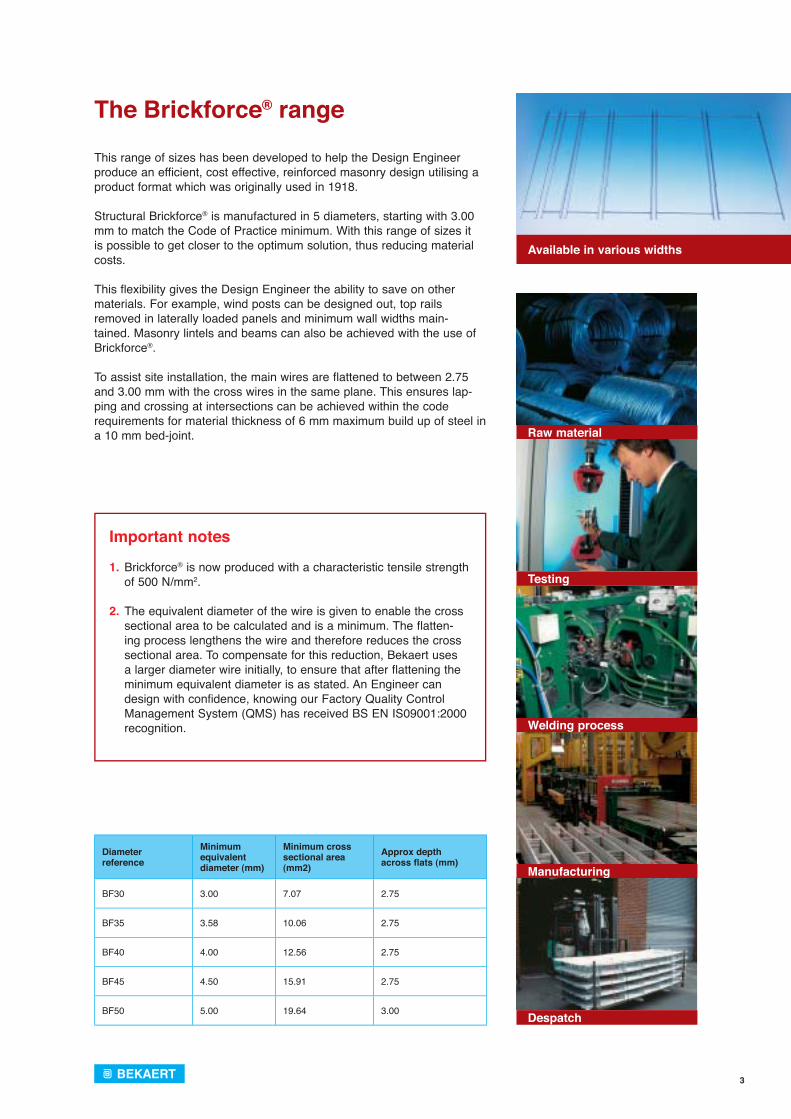
Structural Brickforce® is manufactured in 5 diameters, starting with 3.00 mm to match the Code of Practice minimum. With this range of sizes it is possible to get closer to the optimum solution, thus reducing material costs.
This flexibility gives the Design Engineer the ability to save on other materials. For example, wind posts can be designed out, top rails removed in laterally loaded panels and minimum wall widths main-tained. Masonry lintels and beams can also be achieved with the use of Brickforce®.
To assist site installation, the main wires are flattened to between 2.75 and 3.00 mm with the cross wires in the same plane. This ensures lap-ping and crossing at intersections can be achieved within the code requirements for material thickness of 6 mm maximum build up of steel in a 10 mm bed-joint.
Available in various widths
Raw material
Testing
Welding process
Manufacturing
Despatch
Diameter reference
Minimum equivalentdiameter (mm)
Minimum cross sectional area (mm2)
Approx depthacross fl ats (mm)
BF30 3.00 7.07 2.75
BF35 3.58 10.06 2.75
BF40 4.00 12.56 2.75
BF45 4.50 15.91 2.75
BF50 5.00 19.64 3.00
Important notes
1. Brickforce® is now produced with a characteristic tensile strength of 500 N/mm2.
2. The equivalent diameter of the wire is given to enable the cross sectional area to be calculated and is a minimum. The flatten-ing process lengthens the wire and therefore reduces the cross sectional area. To compensate for this reduction, Bekaert uses a larger diameter wire initially, to ensure that after flattening the minimum equivalent diameter is as stated. An Engineer can design with confidence, knowing our Factory Quality Control Management System (QMS) has received BS EN IS09001:2000 recognition.
4
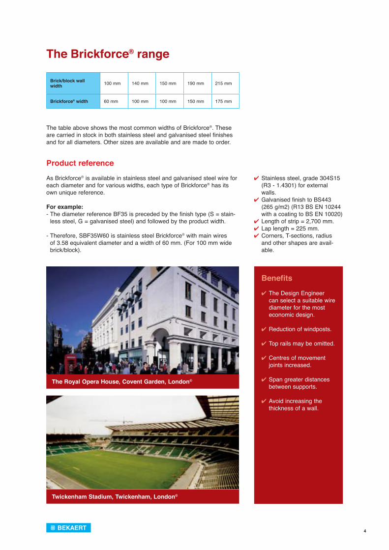
✔ Stainless steel, grade 304S15 (R3 - 1.4301) for external walls.
✔ Galvanised finish to BS443 (265 g/m2) (R13 BS EN 10244 with a coating to BS EN 10020)
✔ Length of strip = 2,700 mm. ✔ Lap length = 225 mm. ✔ Corners, T-sections, radius
and other shapes are avail-able.
Twickenham Stadium, Twickenham, London©
The Royal Opera House, Covent Garden, London©
The Brickforce® range
The table above shows the most common widths of Brickforce®. These are carried in stock in both stainless steel and galvanised steel finishes and for all diameters. Other sizes are available and are made to order.
Product reference
As Brickforce® is available in stainless steel and galvanised steel wire for each diameter and for various widths, each type of Brickforce® has its own unique reference.
For example: - The diameter reference BF35 is preceded by the finish type (S = stain-
less steel, G = galvanised steel) and followed by the product width.
- Therefore, SBF35W60 is stainless steel Brickforce® with main wires of 3.58 equivalent diameter and a width of 60 mm. (For 100 mm wide brick/block).
Brick/block wall width 100 mm 140 mm 150 mm 190 mm 215 mm
Brickforce® width 60 mm 100 mm 100 mm 150 mm 175 mm
Benefits
✔ The Design Engineer can select a suitable wire diameter for the most economic design.
✔ Reduction of windposts.
✔ Top rails may be omitted.
✔ Centres of movement joints increased.
✔ Span greater distances between supports.
✔ Avoid increasing the thickness of a wall.

5
Important notes
The maximum depth of reinforcement becomes critical at laps, cor-ners, intersections and wall tie positions - hence Bekaert's preference for flattened wires. This flattened profile, together with the integral cross wires, enables larger diameters of wire to be used without an increase in the overall steel thickness, therefore, reinforcement conti-nuity can be maintained. By using welded corner units and T-sections etc., within the maximum steel depth of 6 mm the bricklayer has no problems with layer build up, and the bed joint thickness remains as designed.Also, by using a larger diameter at 450 mm centres instead of a smaller one at 225 mm centres, minimum quantities of reinforce-ment are used, construction is faster and wall ties can be easily positioned in the intermediate bed joints.
6. The minimum cover stipulated in BS5628 Part 2 is 15 mm, but it is usual when designing to use 20 mm. This will allow for either raked joints or give the bricklayer 5 mm tolerance when laying the reinforcement.
7. The tables for 215 mm wide block assume the use of collar jointed wall construction in accordance with BS5628 Part 1. The rein-forcement used in Bekaert Bricktie, is made from the same range of wire diameters as Brickforce®, but has 20 mm x 3 mm cross pieces, enabling the wall to be designed as a single leaf.
Design notes
All structural bed joint reinforcement is covered by BS5628 Part 2, and or EN845-3, the Code of Practice for the structural use of rein-forced and pre-stressed masonry. The main points of this code in relation to bed joint reinforcement are listed ....
1. For laterally loaded panels a minimum cross sectional area of rein-forcement at 14 mm2 is required, placed at vertical intervals not exceeding 450 mm. Furthermore, the partial safety factor for the compressive strength of masonry should be taken from clause 27 of BS5628 Part 1.
2. An increase in the limiting dimension is permissible to 60 x the effec-tive thickness and a corresponding increase in panel area is available depending on the support conditions.
3. Various design methods are acceptable, the more popular for lateral load resistance is A5 method three: Design using modified orthogonal ratio. A typical panel design using this method is shown on pages 19 and 20.
4. Durability and material finish are covered in Table 14 of BS5628 Part 2. Galvanised material, unless coated to a minimum weight of 940 g/m2 is only for use in internal walls as the required 940 g/m2 galvanis-ing on small diameter wires is impossible to achieve consistently. For external walls, including the inner leaf of a cavity wall, only austenitic stainless steel is used in line with EN 845-3.
5. To allow bond to develop between reinforcement and mortar a maxi-
mum depth of steel of 6 mm is given, thus allowing 2 mm cover top and bottom. Brickforce®
Bricktie
6
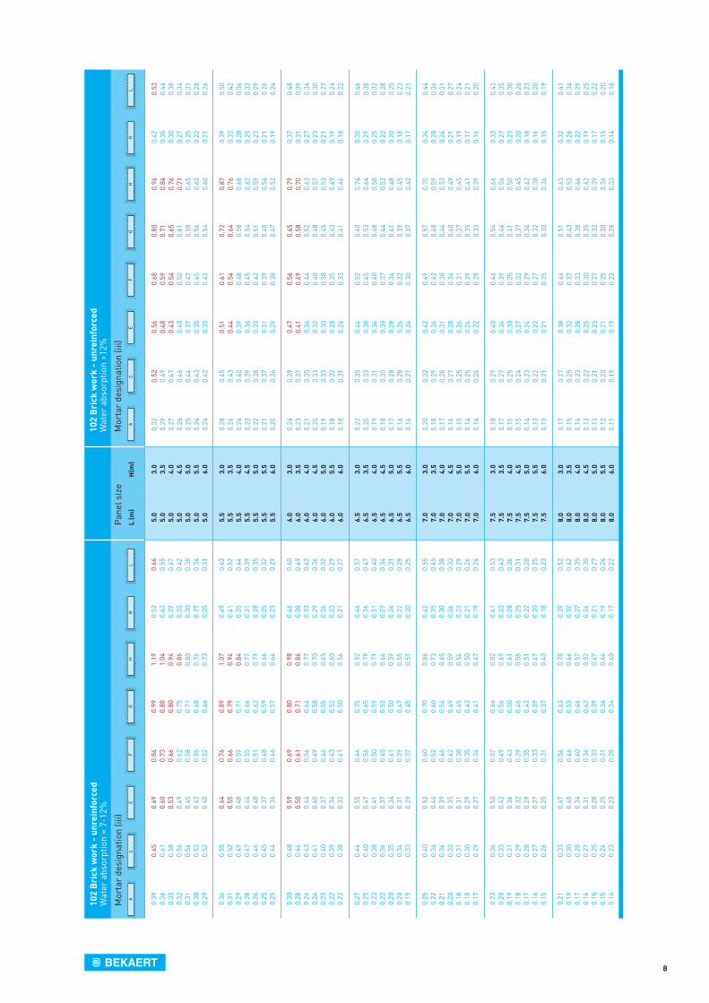
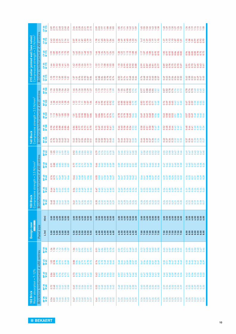
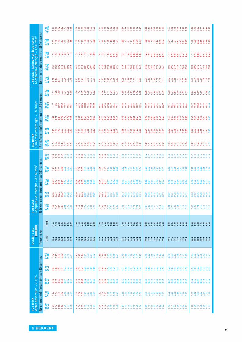
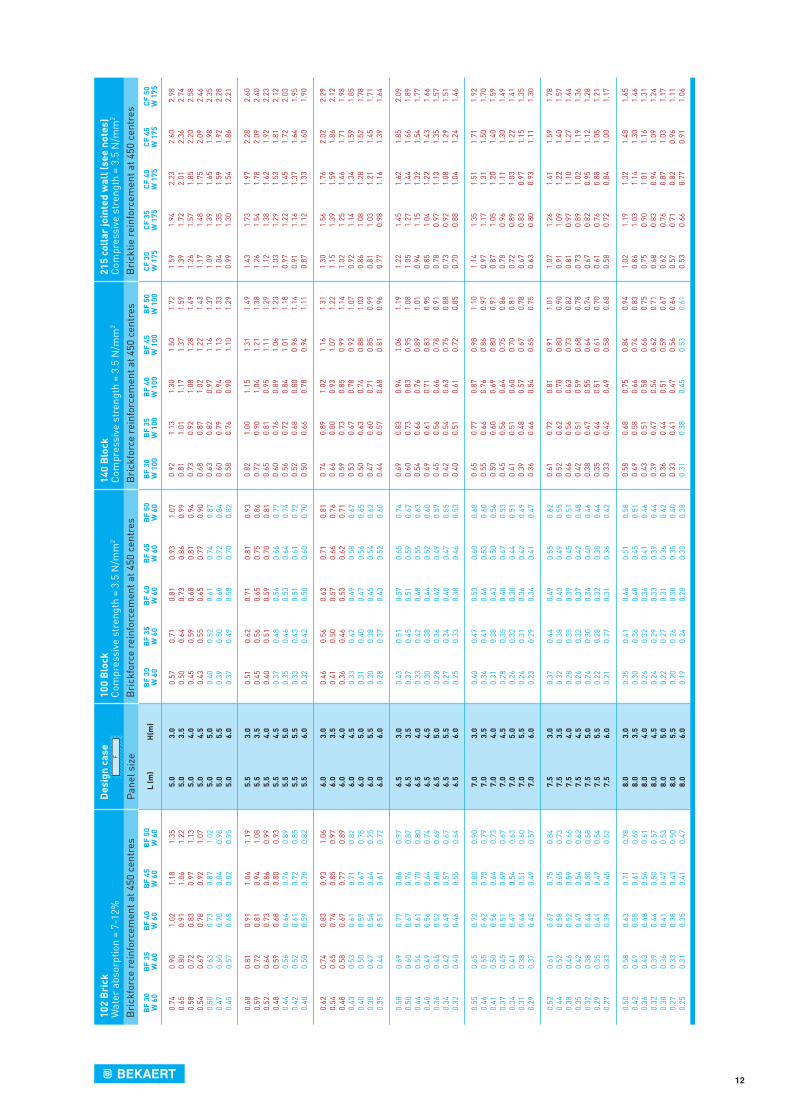
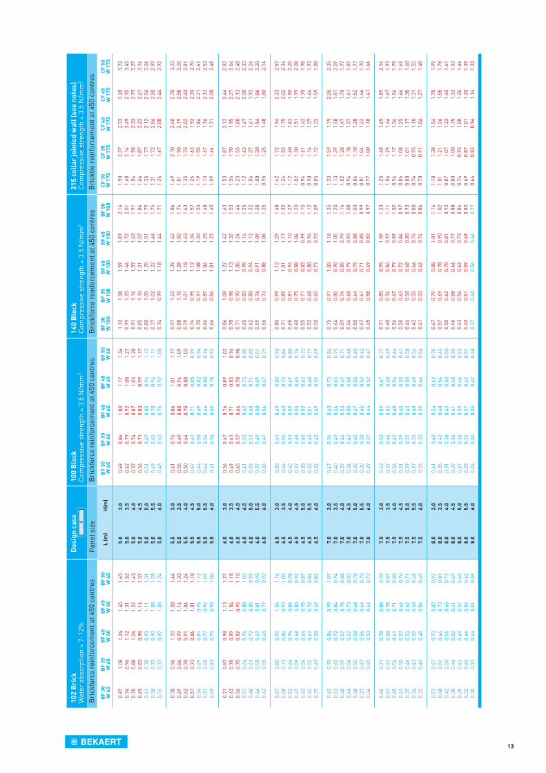
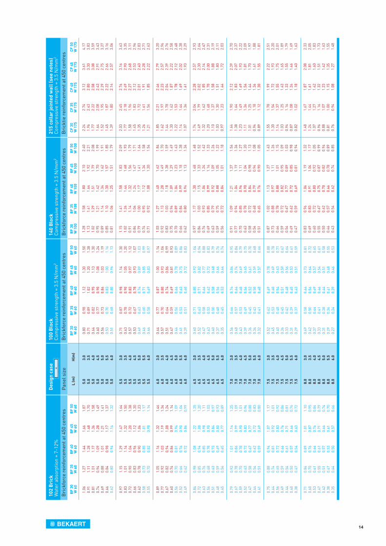
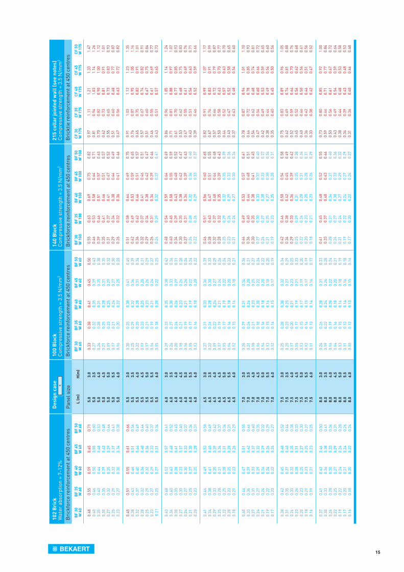
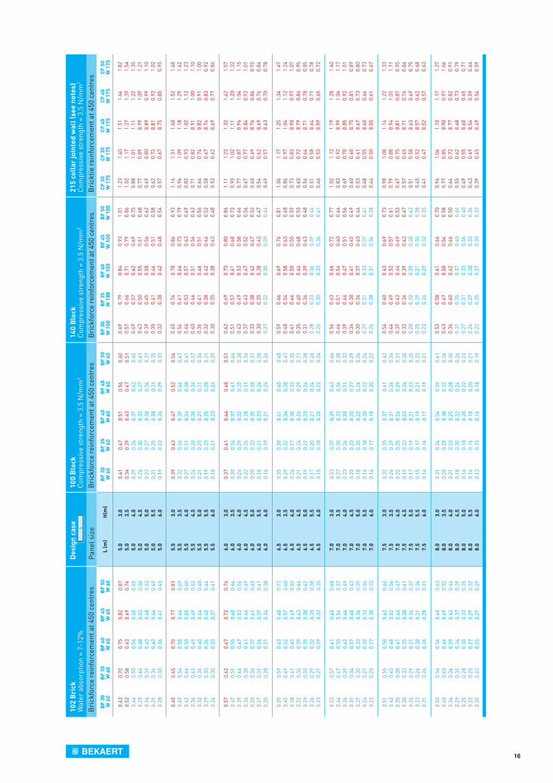
Load tables for reinforcement of laterally loaded masonry panels
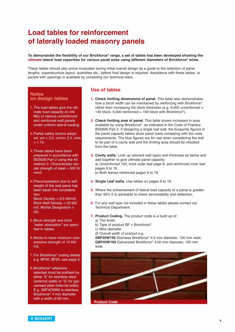
To demonstrate the flexibility of our Brickforce® range, a set of tables has been developed showing the ultimate lateral load capacities for various panel sizes using different diameters of Brickforce® wires.
These tables should also prove invaluable during initial overall design as a guide to the selection of panel lengths, superstructure layout, quantities etc., before final design is required. Assistance with these tables, or panels with openings is available by contacting our technical team.
Noteson design tables
1. The load tables give the ulti-mate load capacity (in kN/M2) of various unreinforced and reinforced wall panels under uniform lateral loading.
2. Partial safety factors adopt-
ed: γm = 3.0, γmm= 2.3, γms = 1.15.
3. These tables have been prepared in accordance with BS5628 Part 2 using the A5 method 3. Characteristic ten-sile strength of steel = 500 N/mm2.
4. Precompression due to self weight of the wall panel has been taken into considera-tion.
Block Density = 6.5 kN/m3. Brick Wall Density = 20 kN/m3. Mortar Designation = (iii).
5. Block strength and brick “water absorption” are speci-fied in tables.
6. Bricks to have minimum com-pressive strength of 15 kN/m2.
7. For Brickforce® coding details e.g. BF30, BF35, see page 3.
8. Brickforce® reference
selected must be prefixed by either ‘S’ for stainless steel (external walls) or ‘G’ for gal-vanised steel (internal walls). E.g. SBF4OW60 is stainless Brickforce® 4 mm diameter with a width of 60 mm.
Use of tables 1. Check limiting dimensions of panel. This table also demonstrates
how a block width can be maintained by reinforcing with Brickforce® rather than increasing the block thickness (e.g. 6,000 unreinforced = 140 block: 6,000 reinforced = 100 block with Brickforce®).
2. Check limiting area of panel. This table shows increases in area available by using Brickforce®, as indicated in the Code of Practice BS5628 Part 2. If designing a single leaf wall, the burgundy figures in the panel capacity tables show panel sizes complying with the code requirements. The blue figures are for use when considering the leaf to be part of a cavity wall and the limiting area should be checked from the table.
3. Cavity walls. Look up relevant wall types and thickness as below and add together to give ultimate panel capacity:
a) Unreinforced 102, brick outer leaf page 8, and reinforced inner leaf pages 9 to 16.
b) Both leaves reinforced pages 9 to 16.
4. Single Leaf walls. Use tables on pages 9 to 16.
5. Where the enhancement of lateral load capacity of a panel is greater than 50% it is advisable to check serviceability and deflection.
6. For any wall type not included in these tables please contact our
Technical Department.
7. Product Coding. The product code is a build up of: a) The finish. b) Type of product BF = Brickforce®. c) Wire diameter. d) Overall width of product e.g. SBF45W150 Stainless Brickforce® 4.5 mm diameter, 150 mm wide. GBF40W100 Galvanised Brickforce® 4.00 mm diameter, 100 mm
wide.
Product Code
7
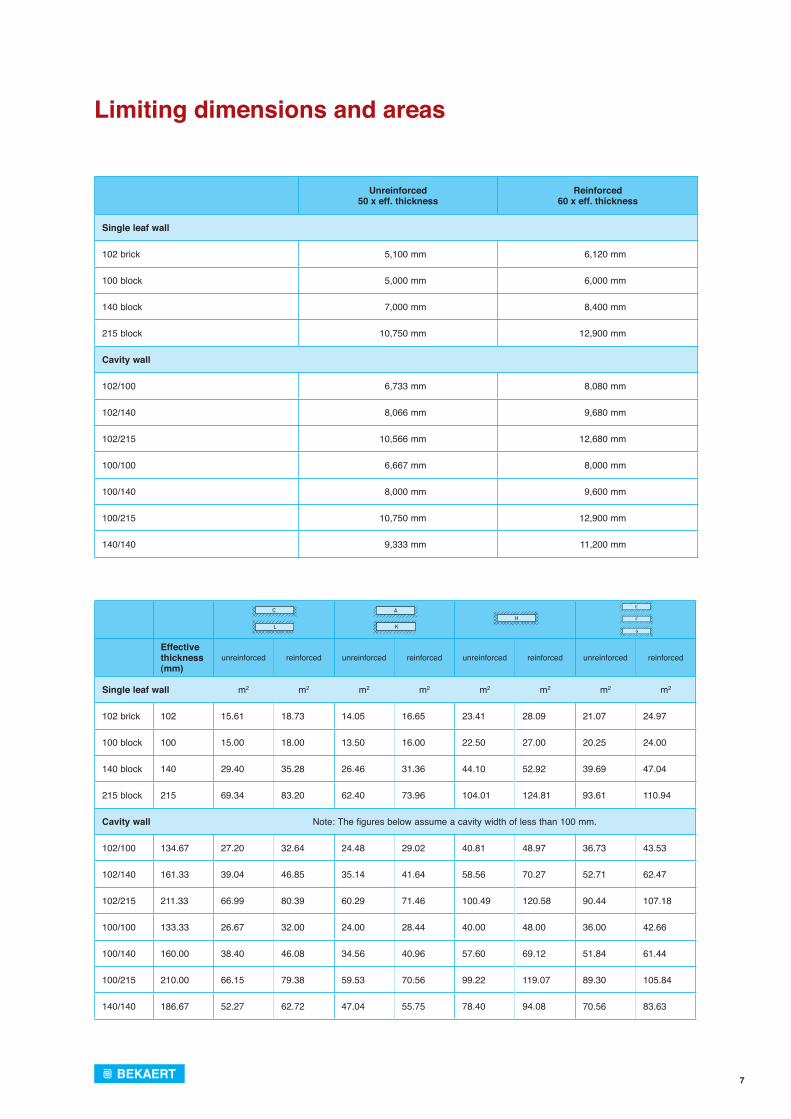
Limiting dimensions and areas
Unreinforced50 x eff. thickness
Reinforced60 x eff. thickness
Single leaf wall
102 brick 5,100 mm 6,120 mm
100 block 5,000 mm 6,000 mm
140 block 7,000 mm 8,400 mm
215 block 10,750 mm 12,900 mm
Cavity wall
102/100 6,733 mm 8,080 mm
102/140 8,066 mm 9,680 mm
102/215 10,566 mm 12,680 mm
100/100 6,667 mm 8,000 mm
100/140 8,000 mm 9,600 mm
100/215 10,750 mm 12,900 mm
140/140 9,333 mm 11,200 mm
Effective thickness (mm)
unreinforced reinforced unreinforced reinforced unreinforced reinforced unreinforced reinforced
Single leaf wall m2 m2 m2 m2 m2 m2 m2 m2
102 brick 102 15.61 18.73 14.05 16.65 23.41 28.09 21.07 24.97
100 block 100 15.00 18.00 13.50 16.00 22.50 27.00 20.25 24.00
140 block 140 29.40 35.28 26.46 31.36 44.10 52.92 39.69 47.04
215 block 215 69.34 83.20 62.40 73.96 104.01 124.81 93.61 110.94
Cavity wall Note: The figures below assume a cavity width of less than 100 mm.
102/100 134.67 27.20 32.64 24.48 29.02 40.81 48.97 36.73 43.53
102/140 161.33 39.04 46.85 35.14 41.64 58.56 70.27 52.71 62.47
102/215 211.33 66.99 80.39 60.29 71.46 100.49 120.58 90.44 107.18
100/100 133.33 26.67 32.00 24.00 28.44 40.00 48.00 36.00 42.66
100/140 160.00 38.40 46.08 34.56 40.96 57.60 69.12 51.84 61.44
100/215 210.00 66.15 79.38 59.53 70.56 99.22 119.07 89.30 105.84
140/140 186.67 52.27 62.72 47.04 55.75 78.40 94.08 70.56 83.63
8

9
10
11
12
13
14
15
16
17
Panels with openings
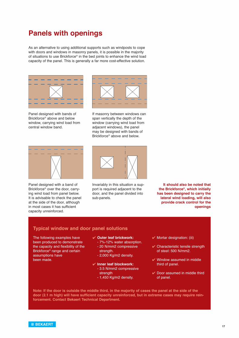
As an alternative to using additional supports such as windposts to cope with doors and windows in masonry panels, it is possible in the majority of situations to use Brickforce® in the bed joints to enhance the wind load capacity of the panel. This is generally a far more cost-effective solution.
Panel designed with bands of Brickforce® above and below window, carrying wind load from central window band.
If masonry between windows can span vertically the depth of the window (carrying wind load from adjacent windows), the panel may be designed with bands of Brickforce® above and below.
Invariably in this situation a sup-port is required adjacent to the door, and the panel divided into sub-panels.
Panel designed with a band of Brickforce® over the door, carry-ing wind load from panel below. It is advisable to check the panel at the side of the door, although in most cases it has sufficient capacity unreinforced.
It should also be noted that the Brickforce®, which initially
has been designed to carry the lateral wind loading, will also provide crack control for the
openings
Typical window and door panel solutions
The following examples have been produced to demonstrate the capacity and flexibility of the Brickforce® range and certain assumptions have been made.
✔ Outer leaf brickwork: - 7%-12% water absorption. - 20 N/mm2 compressive
strength. - 2,000 Kg/m2 density.
✔ Inner leaf blockwork: - 3.5 N/mm2 compressive
strength - 1,450 Kg/m2 density.
✔ Mortar designation: (iii)
✔ Characteristic tensile strength of steel: 500 N/mm2.
✔ Window assumed in middle third of panel.
✔ Door assumed in middle third of panel.
Note: If the door is outside the middle third, in the majority of cases the panel at the side of the door (2.1 m high) will have sufficient capacity unreinforced, but in extreme cases may require rein-forcement. Contact Bekaert Technical Department.
18
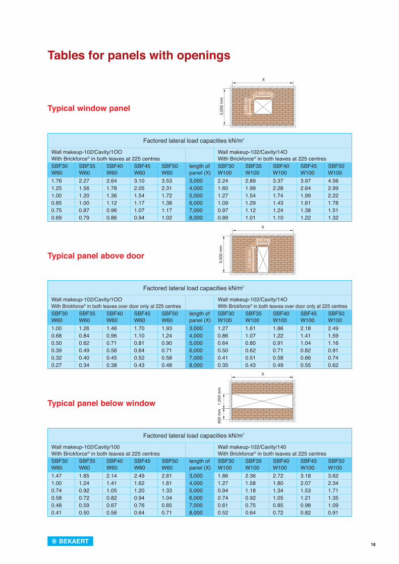
Typical window panel
Typical panel above door
Typical panel below window
X
3,00
0 m
m
1,500 mm
1,20
0 m
m
X
1,20
0 m
m90
0 m
m
X3,
000
mm
900 mm
2,10
0 m
m
Tables for panels with openings
SBF30 SBF35 SBF40 SBF45 SBF50 length of SBF30 SBF35 SBF40 SBF45 SBF50 W60 W60 W60 W60 W60 panel (X) W100 W100 W100 W100 W100 1.76 2.27 2.64 3.10 3.53 3,000 2.24 2.89 3.37 3.97 4.561.25 1.56 1.78 2.05 2.31 4,000 1.60 1.99 2.28 2.64 2.991.00 1.20 1.36 1.54 1.72 5,000 1.27 1.54 1.74 1.99 2.220.85 1.00 1.12 1.17 1.38 6,000 1.09 1.29 1.43 1.61 1.780.75 0.87 0.96 1.07 1.17 7,000 0.97 1.12 1.24 1.38 1.510.69 0.79 0.86 0.94 1.02 8,000 0.89 1.01 1.10 1.22 1.32
SBF30 SBF35 SBF40 SBF45 SBF50 length of SBF30 SBF35 SBF40 SBF45 SBF50 W60 W60 W60 W60 W60 panel (X) W100 W100 W100 W100 W100 1.00 1.26 1.46 1.70 1.93 3,000 1.27 1.61 1.86 2.18 2.490.68 0.84 0.96 1.10 1.24 4,000 0.86 1.07 1.22 1.41 1.590.50 0.62 0.71 0.81 0.90 5,000 0.64 0.80 0.91 1.04 1.160.39 0.49 0.56 0.64 0.71 6,000 0.50 0.62 0.71 0.82 0.910.32 0.40 0.45 0.52 0.58 7,000 0.41 0.51 0.58 0.66 0.740.27 0.34 0.38 0.43 0.48 8,000 0.35 0.43 0.49 0.55 0.62
Wall makeup-102/Cavity/1OO With Brickforce® in both leaves at 225 centres
Wall makeup-102/Cavity/1OO With Brickforce® in both leaves over door only at 225 centres
Wall makeup-102/Cavity/14O With Brickforce® in both leaves at 225 centres
Wall makeup-102/Cavity/14O With Brickforce® in both leaves over door only at 225 centres
Factored lateral load capacities kN/m2
Factored lateral load capacities kN/m2
SBF30 SBF35 SBF40 SBF45 SBF50 length of SBF30 SBF35 SBF40 SBF45 SBF50 W60 W60 W60 W60 W60 panel (X) W100 W100 W100 W100 W100 1.47 1.85 2.14 2.49 2.81 3,000 1.86 2.36 2.72 3.18 3.621.00 1.24 1.41 1.62 1.81 4,000 1.27 1.58 1.80 2.07 2.340.74 0.92 1.05 1.20 1.33 5,000 0.94 1.18 1.34 1.53 1.710.58 0.72 0.82 0.94 1.04 6,000 0.74 0.92 1.05 1.21 1.350.48 0.59 0.67 0.76 0.85 7,000 0.61 0.75 0.85 0.98 1.090.41 0.50 0.56 0.64 0.71 8,000 0.52 0.64 0.72 0.82 0.91
Wall makeup-102/Cavity/100With Brickforce® in both leaves at 225 centres
Wall makeup-102/Cavity/140With Brickforce® in both leaves at 225 centres
Factored lateral load capacities kN/m2
19
Allowable = Md where Md = fkx Z ∴ α(Wkγf) L2 = fkx ZWind load α x L2 γm γm
6 m
7.5 m
∴Wkγf = 1.1 x 103 x 1022 = 0.21 kN/m2
3.0 x 6 x 106 x 7.52 x 0.05
Design calculations
Typical design of wall panel to resist lateral loading
Where lateral loading occurs, and enhanced resistance to the load is required, bed joint reinforcement should be used as required by Clause A2.4 (Annex A) of BS5628 Part 2:2000. This states that it may be assumed the wall will have enhanced lateral load resistance compared with an unreinforced wall, if reinforcement with a minimum cross sectional area of 14 mm2 is placed at vertical centres not exceeding 450 mm.
It is normally more economic to reinforce a wall to resist horizontal pressure than to provide alternative solutions such as intermediate piers, windposts or an increase in wall thickness.
The following calculations show the design case A5 method 3 from BS5628 Part 2 using a modified orthogonal ratio. To enable this method to be used, bending moment co-efficient tables are also provided on pages 21 to 23.
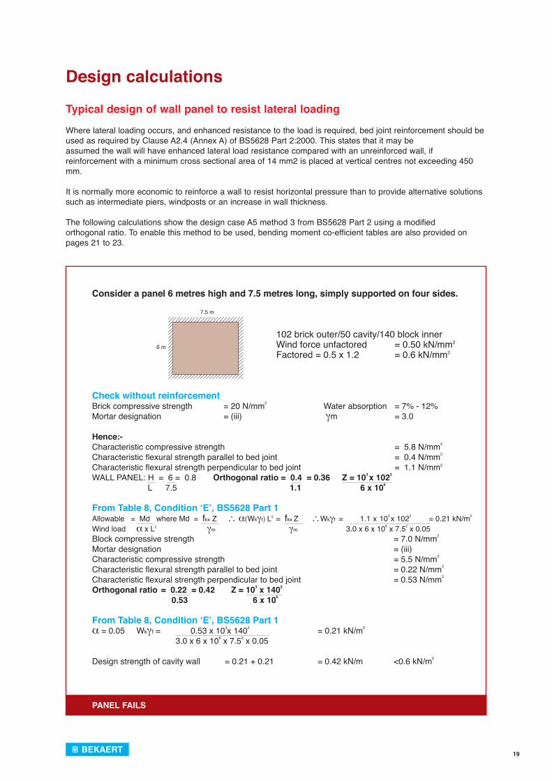
Consider a panel 6 metres high and 7.5 metres long, simply supported on four sides.
102 brick outer/50 cavity/140 block innerWind force unfactored = 0.50 kN/mm2
Factored = 0.5 x 1.2 = 0.6 kN/mm2
Check without reinforcement Brick compressive strength = 20 N/mm2 Water absorption = 7% - 12% Mortar designation = (iii) γm = 3.0
Hence:- Characteristic compressive strength = 5.8 N/mm2
Characteristic fl exural strength parallel to bed joint = 0.4 N/mm2
Characteristic fl exural strength perpendicular to bed joint = 1.1 N/mm2
WALL PANEL: H = 6 = 0.8 Orthogonal ratio = 0.4 = 0.36 Z = 103 x 1022
L 7.5 1.1 6 x 10⁶
From Table 8, Condition ‘E’, BS5628 Part 1
Block compressive strength = 7.0 N/mm2
Mortar designation = (iii)Characteristic compressive strength = 5.5 N/mm2
Characteristic fl exural strength parallel to bed joint = 0.22 N/mm2
Characteristic fl exural strength perpendicular to bed joint = 0.53 N/mm2
Orthogonal ratio
From Table 8, Condition ‘E’, BS5628 Part 1α = 0.05 Wkγf = 0.53 x 103x 1402 = 0.21 kN/m2
3.0 x 6 x 106 x 7.52 x 0.05
Design strength of cavity wall = 0.21 + 0.21 = 0.42 kN/m <0.6 kN/m2
= 0.22 = 0.42 Z = 103 x 1402
0.53 6 x 10⁶
PANEL FAILS
20
Design calculations
Typical design of wall panel to resist lateral loading
Therefore, we will need to enhance with Brickforce® bed joint reinforcement using A5 method 3 (BS5628 Part 2).
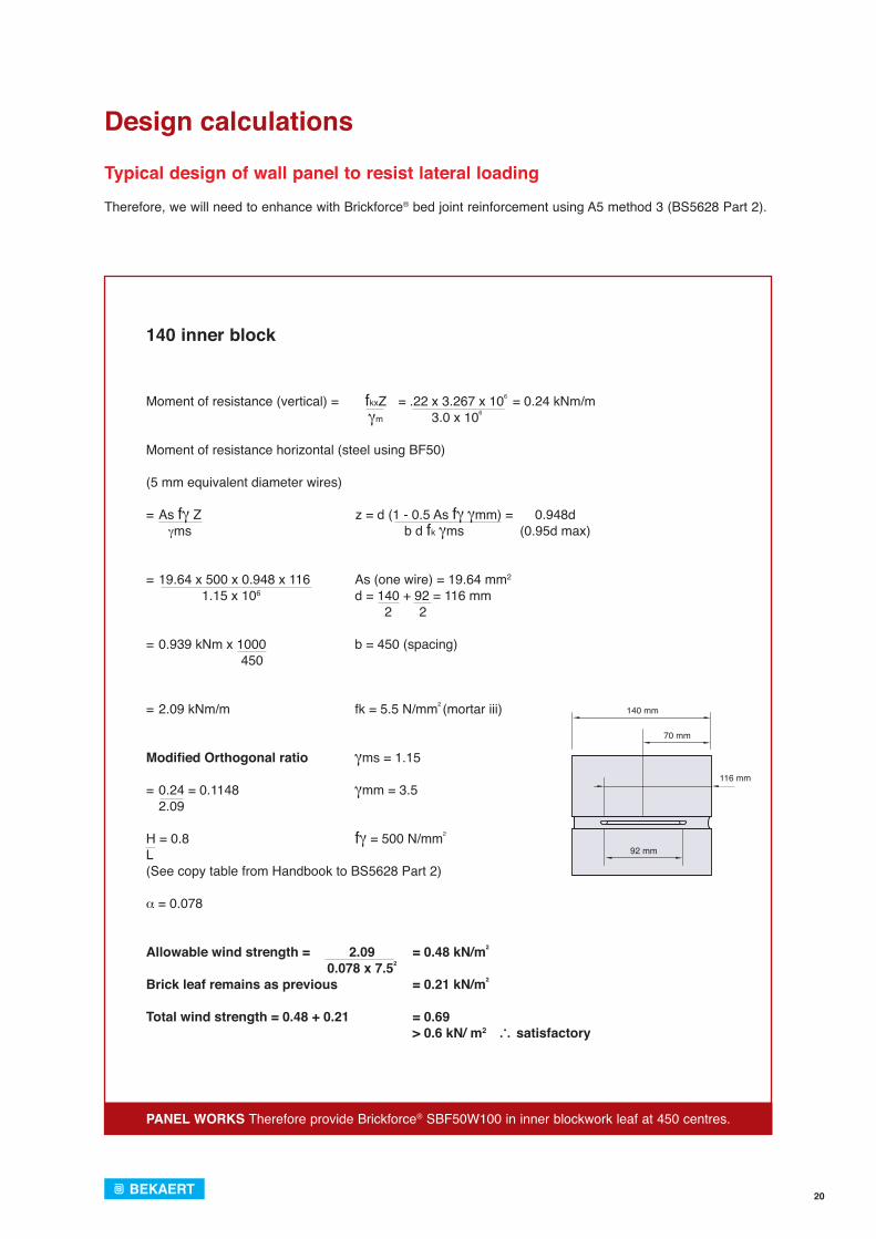
140 inner block
Moment of resistance (vertical) = fkxZ = .22 x 3.267 x 106 = 0.24 kNm/m γm 3.0 x 10⁶
Moment of resistance horizontal (steel using BF50)
(5 mm equivalent diameter wires)
= As fγ Z z = d (1 - 0.5 As fγ γmm) = 0.948d γms b d fk γms (0.95d max)
= 19.64 x 500 x 0.948 x 116 As (one wire) = 19.64 mm2
1.15 x 10⁶ d = 140 + 92 = 116 mm 2 2
= 0.939 kNm x 1000 b = 450 (spacing) 450
= 2.09 kNm/m fk = 5.5 N/mm2 (mortar iii)
Modifi ed Orthogonal ratio γms = 1.15
= 0.24 = 0.1148 γmm = 3.5 2.09
H = 0.8 fγ = 500 N/mm2
L(See copy table from Handbook to BS5628 Part 2)
α = 0.078
Allowable wind strength = 2.09 = 0.48 kN/m2
0.078 x 7.52
Brick leaf remains as previous = 0.21 kN/m2
Total wind strength = 0.48 + 0.21 = 0.69 > 0.6 kN/ m2 ∴ satisfactory
140 mm
70 mm
116 mm
92 mm
PANEL WORKS Therefore provide Brickforce® SBF50W100 in inner blockwork leaf at 450 centres.
21
μα
α α
μα
L
H
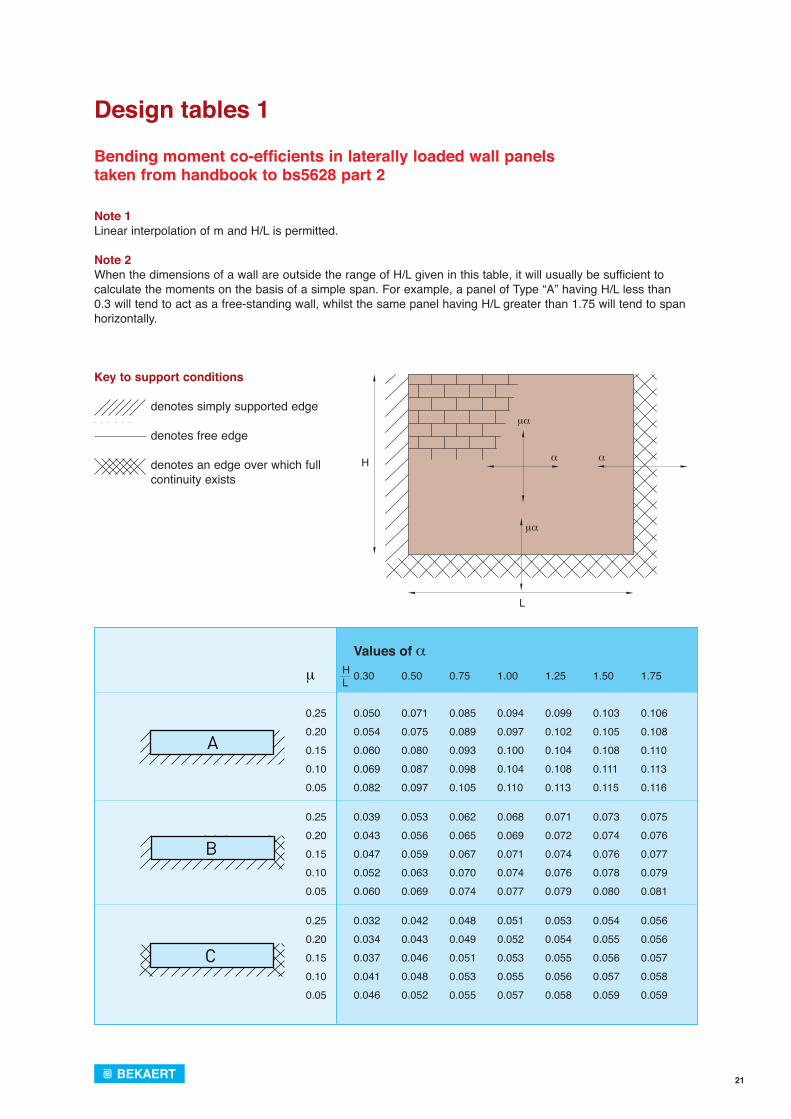
Design tables 1
Bending moment co-efficients in laterally loaded wall panels taken from handbook to bs5628 part 2
Note 1 Linear interpolation of m and H/L is permitted.
Note 2 When the dimensions of a wall are outside the range of H/L given in this table, it will usually be sufficient to calculate the moments on the basis of a simple span. For example, a panel of Type “A” having H/L less than 0.3 will tend to act as a free-standing wall, whilst the same panel having H/L greater than 1.75 will tend to span horizontally.
Values of α μ 0.30 0.50 0.75 1.00 1.25 1.50 1.75
0.25 0.050 0.071 0.085 0.094 0.099 0.103 0.1060.20 0.054 0.075 0.089 0.097 0.102 0.105 0.1080.15 0.060 0.080 0.093 0.100 0.104 0.108 0.1100.10 0.069 0.087 0.098 0.104 0.108 0.111 0.113 0.05 0.082 0.097 0.105 0.110 0.113 0.115 0.116
0.25 0.039 0.053 0.062 0.068 0.071 0.073 0.0750.20 0.043 0.056 0.065 0.069 0.072 0.074 0.0760.15 0.047 0.059 0.067 0.071 0.074 0.076 0.0770.10 0.052 0.063 0.070 0.074 0.076 0.078 0.0790.05 0.060 0.069 0.074 0.077 0.079 0.080 0.081
0.25 0.032 0.042 0.048 0.051 0.053 0.054 0.0560.20 0.034 0.043 0.049 0.052 0.054 0.055 0.0560.15 0.037 0.046 0.051 0.053 0.055 0.056 0.0570.10 0.041 0.048 0.053 0.055 0.056 0.057 0.0580.05 0.046 0.052 0.055 0.057 0.058 0.059 0.059
HL
Key to support conditions
denotes simply supported edge
denotes free edge denotes an edge over which full
continuity exists
22
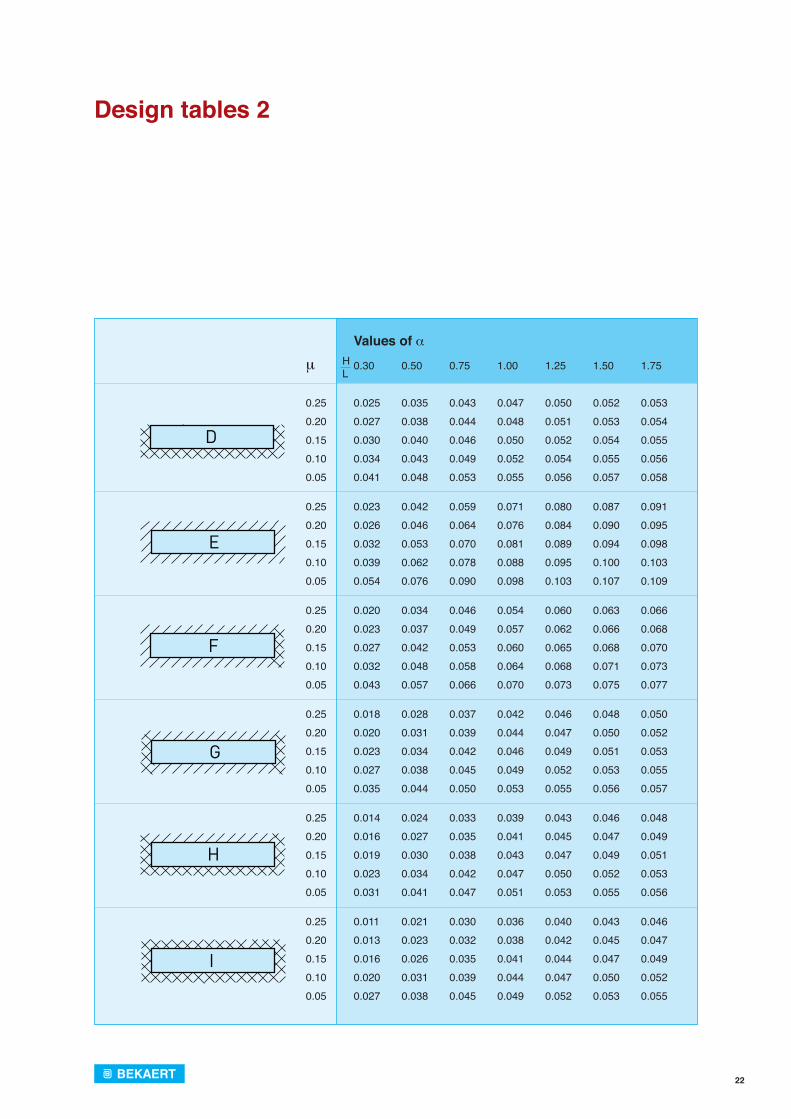
Design tables 2
HL
Values of αμ 0.30 0.50 0.75 1.00 1.25 1.50 1.75
0.25 0.025 0.035 0.043 0.047 0.050 0.052 0.0530.20 0.027 0.038 0.044 0.048 0.051 0.053 0.0540.15 0.030 0.040 0.046 0.050 0.052 0.054 0.0550.10 0.034 0.043 0.049 0.052 0.054 0.055 0.056 0.05 0.041 0.048 0.053 0.055 0.056 0.057 0.058
0.25 0.023 0.042 0.059 0.071 0.080 0.087 0.0910.20 0.026 0.046 0.064 0.076 0.084 0.090 0.0950.15 0.032 0.053 0.070 0.081 0.089 0.094 0.0980.10 0.039 0.062 0.078 0.088 0.095 0.100 0.1030.05 0.054 0.076 0.090 0.098 0.103 0.107 0.109
0.25 0.020 0.034 0.046 0.054 0.060 0.063 0.0660.20 0.023 0.037 0.049 0.057 0.062 0.066 0.0680.15 0.027 0.042 0.053 0.060 0.065 0.068 0.0700.10 0.032 0.048 0.058 0.064 0.068 0.071 0.0730.05 0.043 0.057 0.066 0.070 0.073 0.075 0.077
0.25 0.018 0.028 0.037 0.042 0.046 0.048 0.0500.20 0.020 0.031 0.039 0.044 0.047 0.050 0.0520.15 0.023 0.034 0.042 0.046 0.049 0.051 0.0530.10 0.027 0.038 0.045 0.049 0.052 0.053 0.055 0.05 0.035 0.044 0.050 0.053 0.055 0.056 0.057
0.25 0.014 0.024 0.033 0.039 0.043 0.046 0.0480.20 0.016 0.027 0.035 0.041 0.045 0.047 0.0490.15 0.019 0.030 0.038 0.043 0.047 0.049 0.0510.10 0.023 0.034 0.042 0.047 0.050 0.052 0.0530.05 0.031 0.041 0.047 0.051 0.053 0.055 0.056
0.25 0.011 0.021 0.030 0.036 0.040 0.043 0.0460.20 0.013 0.023 0.032 0.038 0.042 0.045 0.0470.15 0.016 0.026 0.035 0.041 0.044 0.047 0.0490.10 0.020 0.031 0.039 0.044 0.047 0.050 0.0520.05 0.027 0.038 0.045 0.049 0.052 0.053 0.055
23
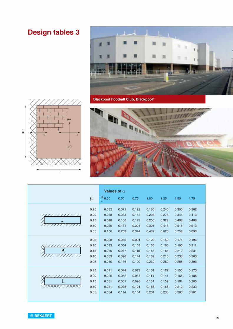
Design tables 3
Values of αμ 0.30 0.50 0.75 1.00 1.25 1.50 1.75
0.25 0.032 0.071 0.122 0.180 0.240 0.300 0.3620.20 0.038 0.083 0.142 0.208 0.276 0.344 0.4130.15 0.048 0.100 0.173 0.250 0.329 0.408 0.4880.10 0.065 0.131 0.224 0.321 0.418 0.515 0.613 0.05 0.106 0.208 0.344 0.482 0.620 0.759 0.898
0.25 0.028 0.056 0.091 0.123 0.150 0.174 0.1960.20 0.033 0.064 0.103 0.136 0.165 0.190 0.2110.15 0.040 0.077 0.119 0.155 0.184 0.210 0.2310.10 0.053 0.096 0.144 0.182 0.213 0.238 0.2600.05 0.080 0.136 0.190 0.230 0.260 0.286 0.306
0.25 0.021 0.044 0.073 0.101 0.127 0.150 0.1700.20 0.025 0.052 0.084 0.114 0.141 0.165 0.1850.15 0.031 0.061 0.098 0.131 0.159 0.184 0.2050.10 0.041 0.078 0.121 0.156 0.186 0.212 0.2330.05 0.064 0.114 0.164 0.204 0.235 0.260 0.281
HL
μα
αα
μα
L
H
Blackpool Football Club, Blackpool©
24
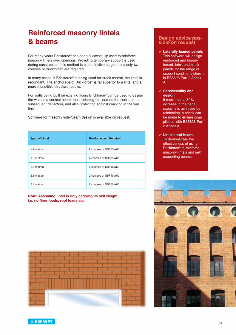
Reinforced masonry lintels & beams
For many years Brickforce® has been successfully used to reinforce masonry lintels over openings. Providing temporary support is used during construction, this method is cost effective as generally only two courses of Brickforce® are required.
In many cases, if Brickforce® is being used for crack control, the lintel is redundant. The anchorage of Brickforce® is far superior to a lintel and a more monolithic structure results.
For walls being built on existing floors Brickforce® can be used to design the wall as a vertical beam, thus reducing the load on the floor and the subsequent deflection, and also protecting against cracking in the wall finish.
Software for masonry lintel/beam design is available on request.
Design advice pos-sible on request
✔ Laterally loaded panelsThis software will design reinforced and unrein-forced, brick and block panels for the range of support conditions shown in BS5628 Part 2 Annex A.
✔ Serviceability and designIf more than a 50% increase in the panel capacity is achieved by reinforcing, a check can be made to ensure com-pliance with BS5628 Part 2 Annex A.
✔ Lintels and beamsTo demonstrate the effectiveness of using Brickforce® to reinforce masonry lintels and self supporting beams.
Span of Lintel Reinforcement Required
1.2 metres 2 courses of SBF35W60
1.5 metres 2 courses of SBF35W60
1.8 metres 2 courses of SBF40W60
2.1 metres 2 courses of SBF40W60
2.4 metres 2 courses of SBF50W60
Note: Assuming lintel is only carrying its self weight. i.e. no floor loads, roof loads etc.
25
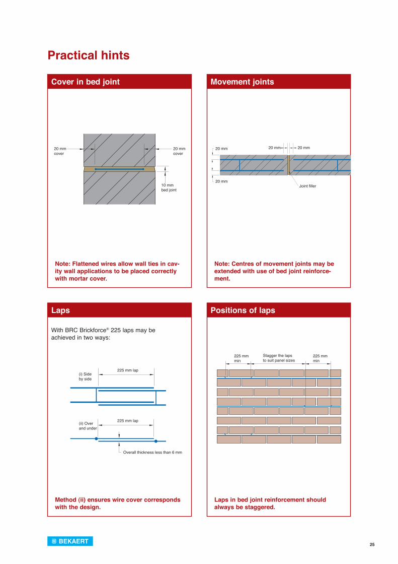
20 mm cover
20 mm cover
10 mm bed joint
225 mm min
225 mm min
Stagger the lapsto suit panel sizes
(i) Side by side
225 mm lap
225 mm lap(ii) Over and under
Overall thickness less than 6 mm
With BRC Brickforce® 225 laps may be achieved in two ways:
Practical hints
Cover in bed joint
Laps
Movement joints
Positions of laps
Note: Flattened wires allow wall ties in cav-ity wall applications to be placed correctly with mortar cover.
Method (ii) ensures wire cover corresponds with the design.
Laps in bed joint reinforcement should always be staggered.
20 mm
20 mm
20 mm 20 mm
Joint fi ller
Note: Centres of movement joints may be extended with use of bed joint reinforce-ment.

26
Development, testing and quality control
Brickforce® together with Bekaert’s other masonry reinforcement products is manufactured with CARES approval. Our Company Quality Management Systems (QMS) have also received BS EN IS0 9001:2000 recognition.
To assist in product traceability, each strip of Brickforce® is ink jetted at regular intervals along one wire with its reference and a manufacturing code. This ensures that the bricklayer uses the correct product and helps the Engineer to easily check on his specification - ensuring every strip can be traced to the day of manufacture and the original material from which it was made.
Bekaert is committed to a sustainable future.
In addition to producing a range of products which enable the construc-tion industry to create sustainable buildings, Bekaert also endeavours to reduce our own impact on the planet, and are working towards ISO 14001 qualification.
Our current in-house commitments include sourcing of sustainable paper for our printed literature and office use, recycling our office waste, and encouraging the use of energy efficient practices at all of our sites.
In addition to most of our products incorporating a high proportion of recyclable materials, many also make use of material that has already been recycled. We continually monitor and make strenuous efforts to reduce our use, or requirement for fossil fuels or other natural resources; whether in control-ling our working environment, in product packaging or delivering finished goods.
Traceability code
Daily testing of flattened wire
Checking raw material for traceability
British standards
Bed joint reinforcement is covered by the following British Standards to which Bekaert products conform:
- BS5628 Part 2 Structural bed joint rein-
forcement (minimum material specification and design requirements).
- BS5628 Part 3 The use of crack control
bed joint reinforcement.
- BS970, BS1554 and BS 10 088
Stainless steel as speci-fied in BS5628 Part 2.
- BS EN 10020 with BS EN 10244 - zinc coating
Galvanised steel wire for use in internal walls.
Production
Brickforce® is made and then checked to ensure that our reinforcement is in accordance with BS 5628-2 for structural reinforcement and BS EN 845-3 Specification for ancillary components for masonry. We test Brickforce® to BS EN 1002-1:2001 Tensile Testing of Metallic Materials for Structural Reinforcement. Regular daily checks are made on the size, strength, flatness and cross-sectional area of the wire. As the flattening process also elongates the wire and reduces the diameter, the production process is started with a larger diameter wire than required, so after the flattening loss of diameter, the minimum cross sectional area as stated is achieved.
27
Acknowledgements
We would like to thank the following organisations for their co-operation and permission to use photographs in the production of this brochure:
- Twickenham Stadium, Twickenham, London - John Mowlem Construction.
- The Royal Opera House, Covent Garden, London - David Barbour and Building Design Partnership.
- Blackpool Football Club, Blackpool - Ballast PLC. - Stoke-on-Trent College and their staff for allowing photography of work
examples.
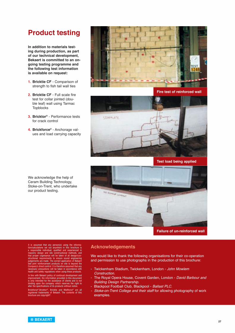
Product testing
In addition to materials test-ing during production, as part of our technical development, Bekaert is committed to an on-going testing programme and the following test information is available on request:
1. Bricktie CF - Comparison of strength to fish tail wall ties
2. Bricktie CF - Full scale fire test for collar jointed (dou-ble leaf) wall using Tarmac Topblocks
3. Bricktor® - Performance tests
for crack control 4. Brickforce® - Anchorage val-
ues and load carrying capacity
We acknowledge the help of Ceram Building Technology, Stoke-on-Trent, who undertake our product testing.
Fire test of reinforced wall
Test load being applied
Failure of un-reinforced wall
It is assumed that any person(s) using the informa-tion/calculations set out anywhere in this brochure is a responsible individual, qualified and experienced in masonry design and site constructional methods, and that proper cognisance will be taken of all design/con-structionaI requirements to ensure sound engineering judgements are made. The correct application of Bekaert bed joint reinforcement products on site is beyond the Company’s direct control. It is therefore assumed that any necessary precautions will be taken in accordance with health and safety regulations when using these products.
In line with Bekaert policy of continual development and improvement, the information provided in this document is only intended for the assistance of clients and is not binding upon the company which reserves the right to alter the specifications of its products without notice.
Brickforce®,Bricktor®, Bricktie and Wallforce® are all registered trademarks of Bekaert. The contents of this brochure are copyright©.
Mad
e b
y A
punta
/ F
eb
ruary
2010 /
53.1
0.0
5
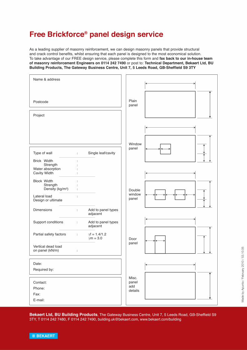
Name address
Plainpanel
Windowpanel
Doublewindowpanel
Doorpanel
Misc.paneladddetails
Postcode
Project
Contact:Phone:Fax:E-mail:
Date:Required by:
Brick
Water absorptionCavity Width
WidthStrength
Block
Lateral loadDesign or ultimate
Dimensions Add to panel typesadjacent
Support conditions Add to panel typesadjacent
Partial safety factors
Vertical dead loadon panel (kN/m)
f = 1.4/1.2m = 3.0
WidthStrengthDensity (kg/m3)
Type of wall Single leaf/cavity
Free Brickforce® panel design service
As a leading supplier of masonry reinforcement, we can design masonry panels that provide structuraland crack control benefits, whilst ensuring that each panel is designed to the most economical solution.To take advantage of our FREE design service, please complete this form and fax back to our in-house team of masonry reinforcement Engineers on 0114 242 7490 or post to: Technical Department, Bekaert Ltd, BU Building Products, The Gateway Business Centre, Unit 7, 5 Leeds Road, GB-Sheffield S9 3TY
Bekaert Ltd, BU Building Products, The Gateway Business Centre, Unit 7, 5 Leeds Road, GB-Sheffi eld S9 3TY, T 0114 242 7480, F 0114 242 7490, [email protected], www.bekaert.com/building