bubble column report
TRANSCRIPT
8/6/2019 Bubble Column Report
http://slidepdf.com/reader/full/bubble-column-report 1/8
Study of Hydrodynamic Characteristics
Of Two Phase Flow Mixture
PMMT Lab ReportSESSION 2010-12
By
Qazi Tanveer Ahmad Khan
MS Process Engineering
8/6/2019 Bubble Column Report
http://slidepdf.com/reader/full/bubble-column-report 2/8
ABSTRACT
This experiment demonstrates the hydrodynamic study of two phase mixture by using bubble
column equipment. In experiment water and air is used as two phase mixture. Initial height of
water column for zero air flowrate was measured, now by increasing air flowrate void fraction,
different flow patterns and pressure drop of two phase mixture was observed. Initial height of water for zero air flowrate was 83 cm,but when air is introduced from the bottom of bubble
colum,first flow pattern observed was bubbly flow. Similarly by increasing air flowrate observed
mixed bubbly and churn flow patterns respectively. Plug flow is not observed because diameter
of column is lager for this gas flowrate and also no annular and flow is observed due to the
reason that water quantity was much high as compared to air flowrate.For all these flow patterns
pressure drop and void fraction are also calculated. Pressure drop and void fraction observed
were maximum for churn flow, 1.102kpa and 0.135 respectively.
8/6/2019 Bubble Column Report
http://slidepdf.com/reader/full/bubble-column-report 3/8
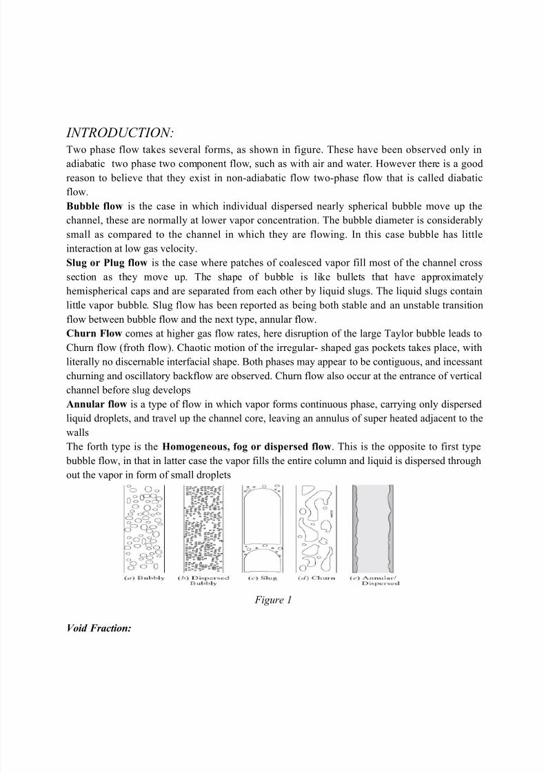
INTRODUCTION:Two phase flow takes several forms, as shown in figure. These have been observed only in
adiabatic two phase two component flow, such as with air and water. However there is a good
reason to believe that they exist in non-adiabatic flow two-phase flow that is called diabatic
flow.
Bubble flow is the case in which individual dispersed nearly spherical bubble move up the
channel, these are normally at lower vapor concentration. The bubble diameter is considerably
small as compared to the channel in which they are flowing. In this case bubble has little
interaction at low gas velocity.
Slug or Plug flow is the case where patches of coalesced vapor fill most of the channel cross
section as they move up. The shape of bubble is like bullets that have approximately
hemispherical caps and are separated from each other by liquid slugs. The liquid slugs contain
little vapor bubble. Slug flow has been reported as being both stable and an unstable transition
flow between bubble flow and the next type, annular flow.
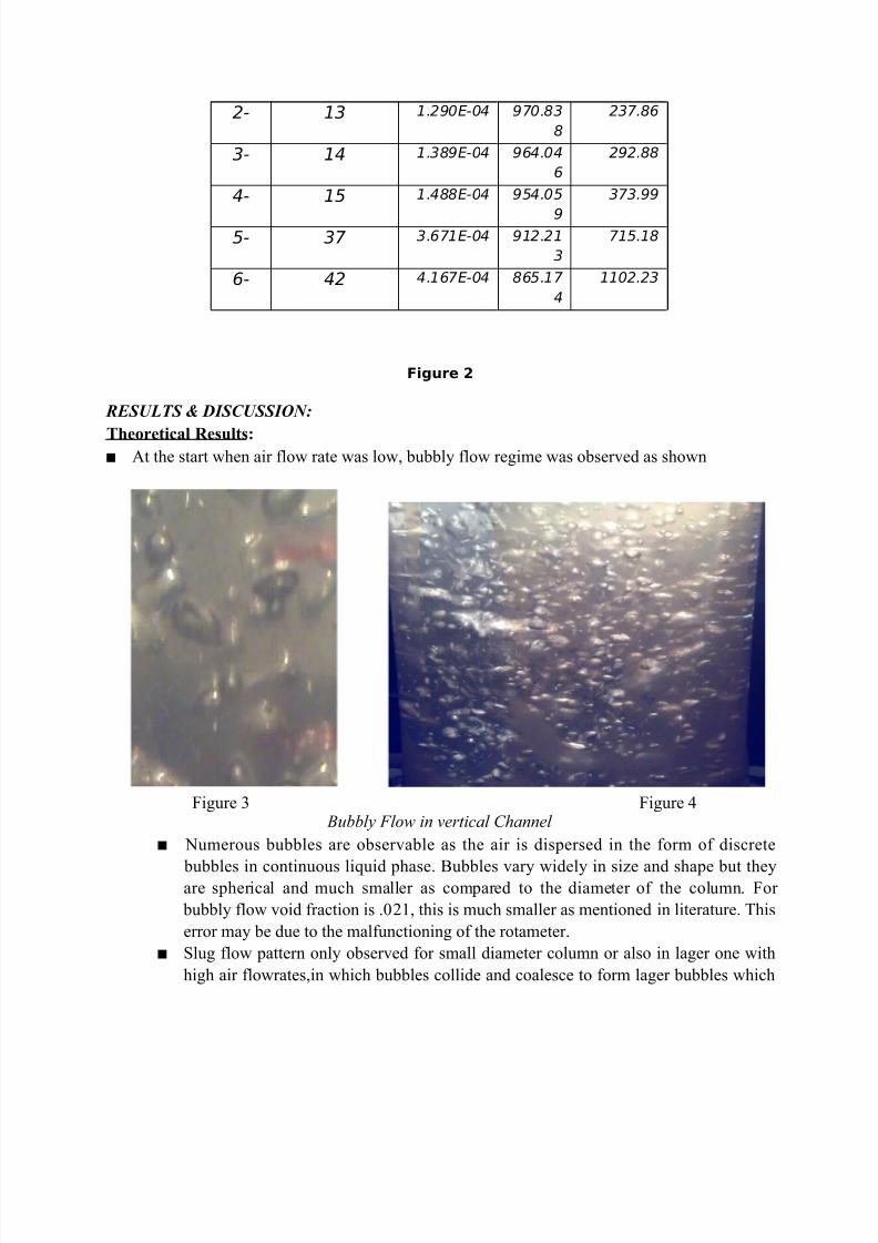
Churn Flow comes at higher gas flow rates, here disruption of the large Taylor bubble leads to
Churn flow (froth flow). Chaotic motion of the irregular- shaped gas pockets takes place, with
literally no discernable interfacial shape. Both phases may appear to be contiguous, and incessant
churning and oscillatory backflow are observed. Churn flow also occur at the entrance of vertical
channel before slug develops
Annular flow is a type of flow in which vapor forms continuous phase, carrying only dispersedliquid droplets, and travel up the channel core, leaving an annulus of super heated adjacent to the
walls
The forth type is the Homogeneous, fog or dispersed flow. This is the opposite to first type
bubble flow, in that in latter case the vapor fills the entire column and liquid is dispersed through
out the vapor in form of small droplets
Figure 1
Void Fraction:
8/6/2019 Bubble Column Report
http://slidepdf.com/reader/full/bubble-column-report 4/8
It is defined as the ratio of the volum of vapor in the mixture to the Total Volume of the bed.It is
very important parameter for two phase flow as it si the key to determine the other physical
parameter in two phase flows like density, viscosity of the mixture as well as relative abverage
velocity of two phases. It has great importance for heat transfer and pressure drop calculations.
Pressure Drop:
Pressure loses in two phase gas- liquid system varies from single phase because an interface can
be smooth or rough depending upon the flow regime, as in churn flow there is no definite
boundary or interface. Two-phase pressure drop may be up to a factor of 10 higher than those in
single phase.
Most of the correlations for pressure drop prediction are empirical so they are limited by the
range of applicability. The pressure drop can vary significantly between different regimes.
Various models have been formed to predict pressure drop. One of then is as follows.The basis
of correlation is that the two phase pressure drop is equal to single phase pressure drop of either
phase multiplied by a factor that is derived by the single phase pressure drop of the two phases.
Theoretically a modulus of pressure drop is calculated and is multiplied by the gas phase pressure drop. This modulus is calculated by different correlations each stand for one type of
flow regime.
Here pressure drop has been calculated with the help of void fraction and static head.. Pressure
drop increases with the increase in void fraction. Experimental ranges are given in tabulated
form.
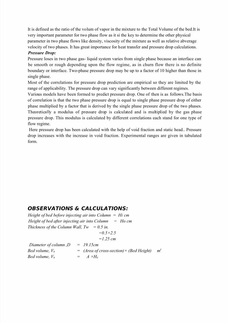
OBSERVATIONS & CALCULATIONS: Height of bed before injecting air into Column = Hi cm
Height of bed after injecting air into Column = Ho cm
Thickness of the Column Wall, Tw = 0.5 in.=0.5×2.5
=1.25 cm
Diameter of column ,D = 19.15cm
Bed volume, V b = (Area of cross-section)× (Bed Height) m3
Bed volume, V b = A ×H 0
8/6/2019 Bubble Column Report
http://slidepdf.com/reader/full/bubble-column-report 5/8
Area of Cross-section, A = ((π/4)×D2 )
= 0.0283m
Void Fraction, α = Volume of airTotal volume of bed
Void Fraction = (A×∆H)/V b
Table 1 Sr.No
.
Gas Flow rate
(L/m)
Hi
(cm)
Ho
(cm)
∆H
(cm)Flow regime
V b
m3α
1- 12 83 84.8 1.8 Bubbly 0.02399 0.0210
2- 13 83 85.5 2.5 Bubbly 0.0239 0.0292
3- 14 83 86.1 3.1Mixed
bubbly0.0241 0.0360
4- 15 83 87 4
Mixed
bubbly 0.0243 0.0460
5- 37 83 91 8 Churn 0.02548 0.0879
6- 42 83 96 13 Churn 0.0268 0.135
B)- PRESSURE DROP CALCULATION:
Pressure Drop ,∆P = ρm×g×∆H
Where;
ρm = density of Mixture
g= Gravitational constant
=9.8 m/sec2
∆H= Bed Expansion
ρm = α×ρ A + (1- α)×ρW
ρ A =1.29kg/m3
ρW =1000kg/m3
Superficial velocity,Ģ = Gas Volumetric Flow rate/Area of cross-section of column
Table 2Sr.N
o.
Gas Flow
rate
(L/m)
Ģ
m/sec
ρm
kg/m3
∆P
pa
1- 12 1.190E-04 979.02
7
172.70
8/6/2019 Bubble Column Report
http://slidepdf.com/reader/full/bubble-column-report 6/8
2- 13 1.290E-04 970.83
8
237.86
3- 14 1.389E-04 964.04
6
292.88
4- 15 1.488E-04 954.05
9
373.99
5- 37 3.671E-04 912.21
3
715.18
6- 42 4.167E-04 865.17
4
1102.23
Figure 2
RESULTS & DISCUSSION:
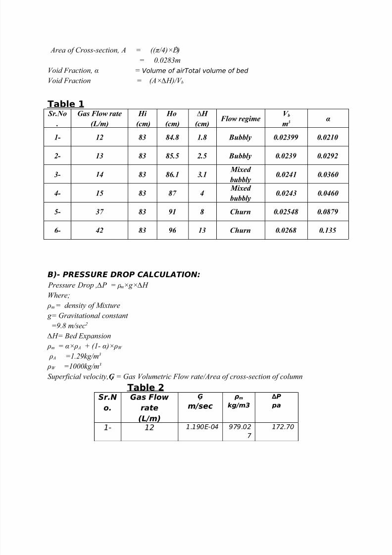
Theoretical Results: At the start when air flow rate was low, bubbly flow regime was observed as shown
Figure 3 Figure 4 Bubbly Flow in vertical Channel
Numerous bubbles are observable as the air is dispersed in the form of discrete
bubbles in continuous liquid phase. Bubbles vary widely in size and shape but theyare spherical and much smaller as compared to the diameter of the column. For
bubbly flow void fraction is .021, this is much smaller as mentioned in literature. This
error may be due to the malfunctioning of the rotameter.
Slug flow pattern only observed for small diameter column or also in lager one with
high air flowrates,in which bubbles collide and coalesce to form lager bubbles which
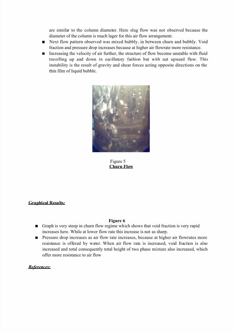
8/6/2019 Bubble Column Report
http://slidepdf.com/reader/full/bubble-column-report 7/8

8/6/2019 Bubble Column Report
http://slidepdf.com/reader/full/bubble-column-report 8/8
1) http://wins.engr.wisc.edu/teaching/mpfBook.2) Moustafa Ghiaasiaan: Two Phase Flow Boiling and Condensation In
Conventional and Miniature systems, Cambridge University press, UK, 2008.