building a light indoor foamy aircraft - flying · pdf filebuilding a light indoor foamy...
TRANSCRIPT
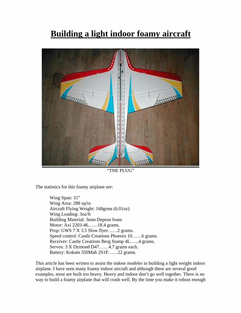
Building a light indoor foamy aircraft
“THE PLUG”
The statistics for this foamy airplane are:
Wing Span: 31”Wing Area: 288 sq/inAircraft Flying Weight: 168grms (6.01oz)Wing Loading: 3oz/ftBuilding Material: 3mm Depron foamMotor: Axi 2203-46……18.4 grams.Prop: GWS 7 X 3.5 Slow flyer……2 grams.Speed control: Castle Creations Phoenix 10……6 grams.Receiver: Castle Creations Berg Stamp 4L…...4 grams.Servos: 3 X Dymond D47……4.7 grams each.Battery: Kokam 350Mah 2S1P……22 grams.
This article has been written to assist the indoor modeler in building a light weight indoorairplane. I have seen many foamy indoor aircraft and although there are several goodexamples, most are built too heavy. Heavy and indoor don’t go well together. There is noway to build a foamy airplane that will crash well. By the time you make it robust enough

to handle any crash, all it will do, is crash. You will have to fly it so fast that nothingshort of an indoor football stadium will be big enough to fly it in. Since most indoorvenues are the size of a high school basketball court, speed and weight are big concerns.You will need to be able to fly slowly and in control at all times. Light weight planesallow you to do this with ease.The method described in this article is by no means the only way to build a light aircraft.However, it is a way that I have found to be both easy and inexpensive. Also, it isguaranteed to fly well.I have broken it down into three sections. The first section is dedicated to selecting anairplane design, selecting equipment, cutting it out and finally, giving it your favoritepaint scheme. The second section will cover the basic construction with several buildingtips along the way. And finally, section three is the addition of the drive system, radiogear and rigging the plane for flight. I will discuss trimming and mixing at the end of thisphase as well.The plane I have chosen to demonstrate my method is called “The Plug”. It is an F3Pmodel. F3P is the official class of indoor competition.
Section 1:Choosing a design
There are several good F3P designs out there. Either, talk to your local indoor clubmembers and see what they like, or serf the net until you find one that catches your eye.There are a few things to keep in mind when you are choosing your design. The airplaneshould be somewhere around the 30” to 40” wingspan. The plane should be made with amaximum of 3mm foam. Anything thicker will be too heavy. Three servos is fairlystandard, one on ailerons, one on rudder and one on elevator. However, there is nothingwrong with using a 4th servo, allowing you to use one per aileron. If you are planning ondoing 4D flying, you will need the fourth servo for the propeller. Resist buying a servojust because it is cheap. Servo centering and torque is more important than inexpensive.Just try to buy ones that weigh less than 8 grams. Any three, four or five channel receiverdesigned for indoors is acceptable. Again, one that has the case removed to keep theweight down to less than 10 grams is preferable. A good Outrunner motor with a brandname speed controller is a good investment. The weight should be no more than 25 gramsfor the motor and 5 grams for the speed control. Some people like the brushed gearedmotors. That is a personal choice. However, I have found that there is a huge weightpenalty for this style of motor. Batteries are one of the areas that most people over buy,consequently adding a lot of unnecessary weight to their model. Most hobby store salesstaff tries to sell you what they have in stock and not what you really need. The batteriesyou choose should have a high “C” rating. Basically this means that your battery canpump out high amps during discharge to give your motor a lot of “oomph” withoutkilling the battery. This is necessary to get yourself out of trouble in the gym. I guaranteethat you will get yourself in trouble and power is your friend. You will not fly more thanabout 10 to 12 minutes indoors due to the concentration required. So a large Mah rating isnot needed. Anything less than 640 Mah with three cells should be ok if the weight is lessthan 50 grams. I find that I have been leaning towards the lighter 2 cell high dischargepacks lately. I am still getting 10 minutes of 3D flight time with these smaller, lighter
packs. Although admittedly they don’t have the same power as a 3 cell pack, I can stilldrill the ceiling if I go to full throttle on an up line. And, they weigh only 23 grams. Imust also inform you at this time, the weights I have given you for the radio gear are amaximum and a guideline only. Anywhere you can save weight is good. Note in the“statistics” section on the previous page, the weights of the equipment that I use. All thisequipment was purchased at local hobby shops. None of it is a special order. I’m surewith a little research that you can find the same equipment or better for less of a weightpenalty.
Section 2:Construction
Buy a piece of 24” x 36” 3mm Depron foam. If your plane selection is a big one, buy twopieces. Select a set of plans. With your favorite plans you now need to get the designfrom the paper to the foam. You can free hand the plans onto the foam or cut up yourplans and use them as templates or make wood templates. If you have a kit that is alreadycut out, you are a head of the game. I like to get a second copy of the plans. I then cut upthe second copy to make wood templates with. I do this by spraying contact cement(3M’s spray 77) on the back of the plans, then placing the plans on a sheet of 1/8th lightply. A 1/8”door skin works well too. Many people have come up with other suitablematerials for the templates. They just need to be stiff and reusable. I then cut the piecesout with my scroll saw. Sand the edges smooth so the knife won’t catch an edge. With alittle work, you can have a set of templates in an hour or so. Now you can make manycopies of your favorite plane in minutes. At this point, I simply place the templates on thefoam and start cutting out the parts. The idea is to kit the plane.Here is a tip for cutting foam. Depron foam is a very course material. X-Acto bladesbecome dull in a very short period of time. I generally go through about five or sixnumber eleven blades just to cut out one plane. This may sound excessive to somehowever, I never get tear out. When the blade becomes dull, the foam will tear or snagcausing a tear out. This leaves a mangled edge that can destroy the look of your newplane. If it is a critical part, such as wing slots, tear out can destroy the part completely.Then you have to buy more foam. I get nice clean edges by simply replacing the blades assoon as I feel any kind of snag or blade catch, no matter how light. If it is an importantcut, as mentioned above, I just replace the blade before I begin. I may go through over100 blades in one season. Then again, I will build about 18+ foamies in a season. If youare proficient at sharpening blades, you will save yourself some money by reusing themover and over again. Maybe even enough to buy some more foam for another few planes.
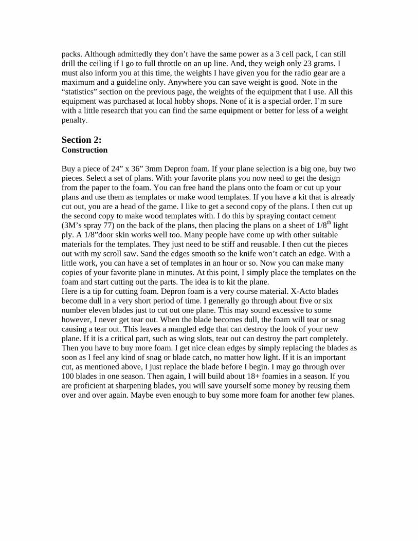
Here is a copy of the plans for “The Plug”.
Now it is time to start kitting “The Plug”. Cut out all the pieces and get them ready forpaint. Using painter’s tape, layout your paint design on the foam pieces. Try to keep itsimple at first. If you make your plane too pretty, you won’t want to crash it. The idea offoamy flying is to make inexpensive planes that are cheap and easy to replace. That wayyou won’t feel bad if you have a mishap. And, you will have a mishap. Have you evernoticed how well you can fly a simulator? Without the fear of crashing, ones mind isclear to concentrate on the maneuver, not the crash. So make your first few paint designssimple, keeping in mind that they are disposable planes. This way your learning curvewill be incredibly steep. Plus, your flying will become much more enjoyable. You willnotice the paint design that I have chosen is very simple and quick to do. I paint the foamwith an inexpensive acrylic paint that I purchase from Michael’s art supplies. I apply itwith cheap foam brushes. The paint sells for about $2 for 8fl.oz bottle.That is enough paint for many planes. The brushes run around $0.65 a piece. If you buythe brushes in a multi pack, they will be even cheaper yet. I use about four differentcolors on most of my planes. Tip: Brush your paint from the tape to the foam in a verylight coat for the first coat. Give this layer time to dry. That is about 30 minutes withoutheat. If you have a heat gun, you can dry this layer in about 3 minutes. Just be careful notto melt your foam. Apply just enough heat on a low setting to dry the paint, not heat the
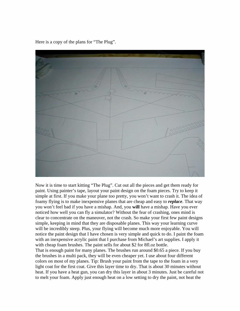
foam. Foam will warp and become brittle with excess heat. The next coat of paint willusually be enough to get a nice even coat. Let this layer dry and peel off the tapecarefully. If you have done it right, you will have very sharp paint lines. The key is thelight first coat.
This stage took me about 2.5 hours to do. That includes painting both sides.
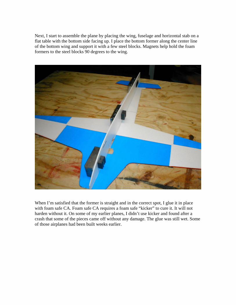
Next, I start to assemble the plane by placing the wing, fuselage and horizontal stab on aflat table with the bottom side facing up. I place the bottom former along the center lineof the bottom wing and support it with a few steel blocks. Magnets help hold the foamformers to the steel blocks 90 degrees to the wing.
When I’m satisfied that the former is straight and in the correct spot, I glue it in placewith foam safe CA. Foam safe CA requires a foam safe “kicker” to cure it. It will notharden without it. On some of my earlier planes, I didn’t use kicker and found after acrash that some of the pieces came off without any damage. The glue was still wet. Someof those airplanes had been built weeks earlier.
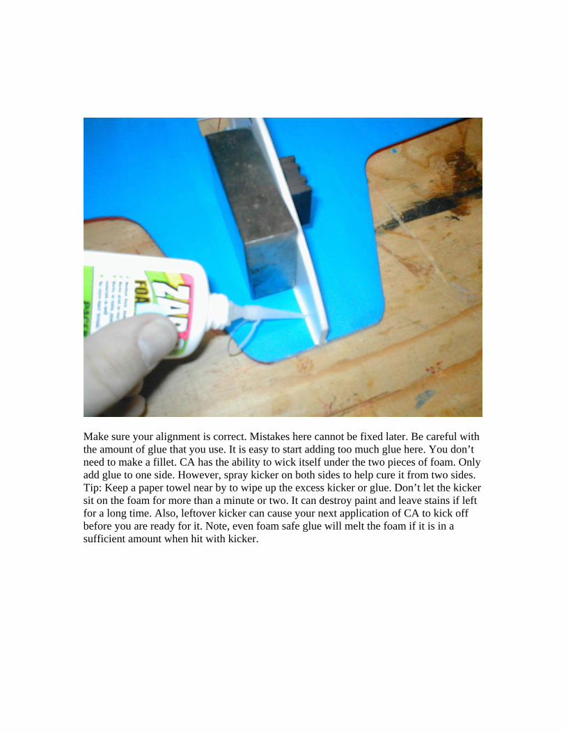
Make sure your alignment is correct. Mistakes here cannot be fixed later. Be careful withthe amount of glue that you use. It is easy to start adding too much glue here. You don’tneed to make a fillet. CA has the ability to wick itself under the two pieces of foam. Onlyadd glue to one side. However, spray kicker on both sides to help cure it from two sides.Tip: Keep a paper towel near by to wipe up the excess kicker or glue. Don’t let the kickersit on the foam for more than a minute or two. It can destroy paint and leave stains if leftfor a long time. Also, leftover kicker can cause your next application of CA to kick offbefore you are ready for it. Note, even foam safe glue will melt the foam if it is in asufficient amount when hit with kicker.
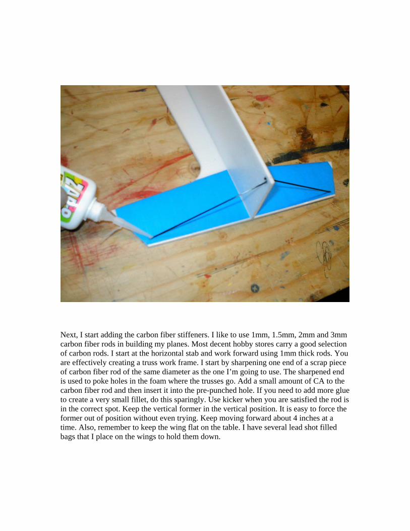
Next, I start adding the carbon fiber stiffeners. I like to use 1mm, 1.5mm, 2mm and 3mmcarbon fiber rods in building my planes. Most decent hobby stores carry a good selectionof carbon rods. I start at the horizontal stab and work forward using 1mm thick rods. Youare effectively creating a truss work frame. I start by sharpening one end of a scrap pieceof carbon fiber rod of the same diameter as the one I’m going to use. The sharpened endis used to poke holes in the foam where the trusses go. Add a small amount of CA to thecarbon fiber rod and then insert it into the pre-punched hole. If you need to add more glueto create a very small fillet, do this sparingly. Use kicker when you are satisfied the rod isin the correct spot. Keep the vertical former in the vertical position. It is easy to force theformer out of position without even trying. Keep moving forward about 4 inches at atime. Also, remember to keep the wing flat on the table. I have several lead shot filledbags that I place on the wings to hold them down.
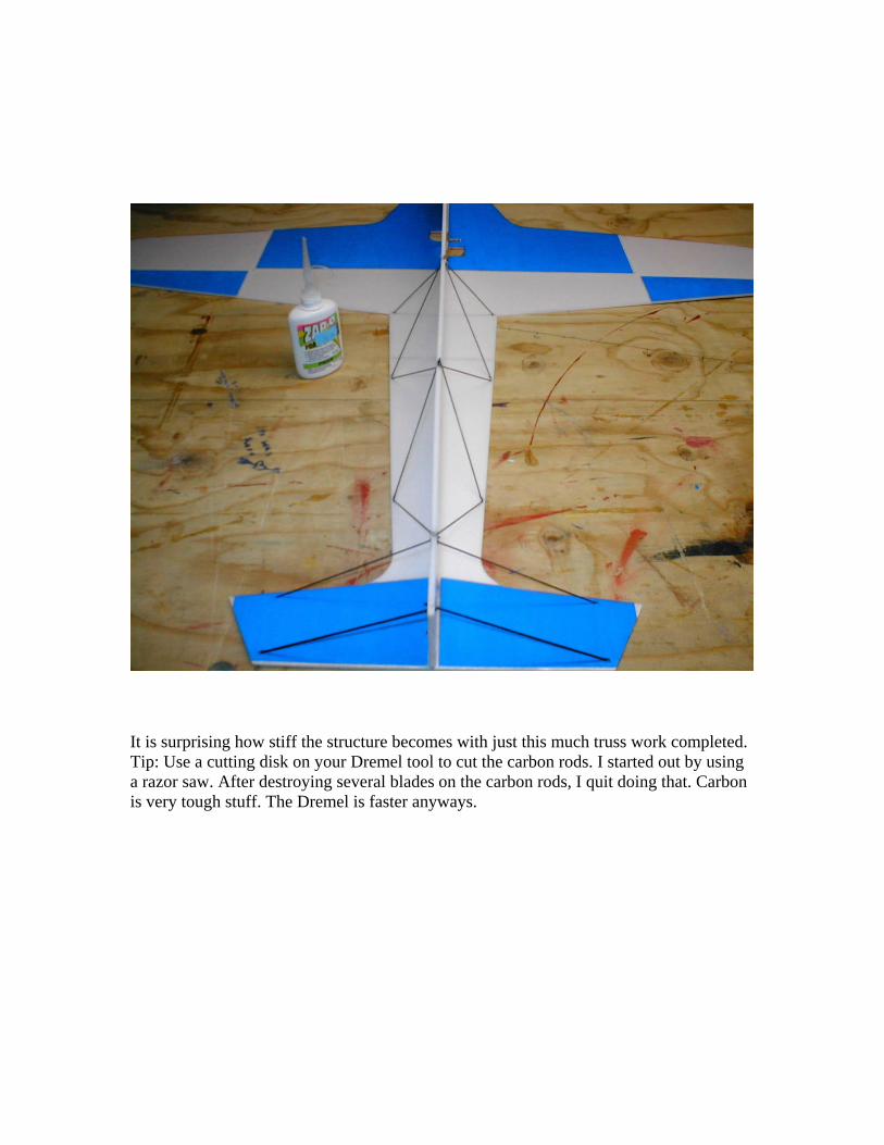
It is surprising how stiff the structure becomes with just this much truss work completed.Tip: Use a cutting disk on your Dremel tool to cut the carbon rods. I started out by usinga razor saw. After destroying several blades on the carbon rods, I quit doing that. Carbonis very tough stuff. The Dremel is faster anyways.
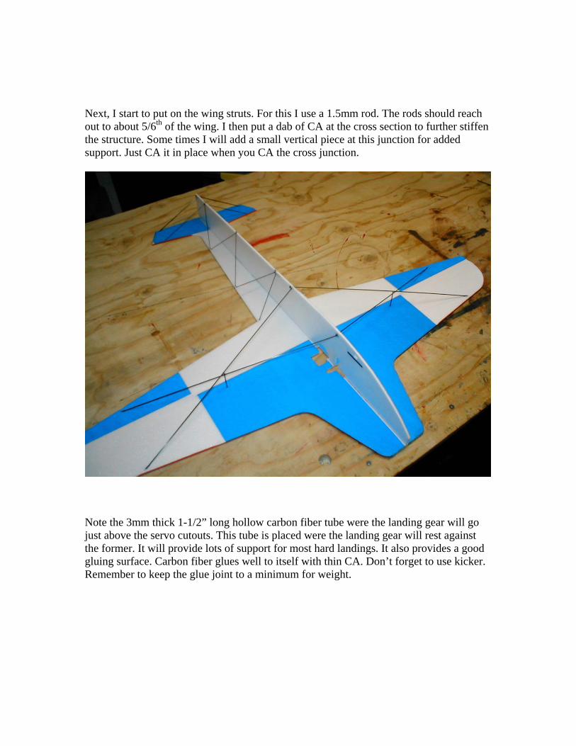
Next, I start to put on the wing struts. For this I use a 1.5mm rod. The rods should reachout to about 5/6th of the wing. I then put a dab of CA at the cross section to further stiffenthe structure. Some times I will add a small vertical piece at this junction for addedsupport. Just CA it in place when you CA the cross junction.
Note the 3mm thick 1-1/2” long hollow carbon fiber tube were the landing gear will gojust above the servo cutouts. This tube is placed were the landing gear will rest againstthe former. It will provide lots of support for most hard landings. It also provides a goodgluing surface. Carbon fiber glues well to itself with thin CA. Don’t forget to use kicker.Remember to keep the glue joint to a minimum for weight.
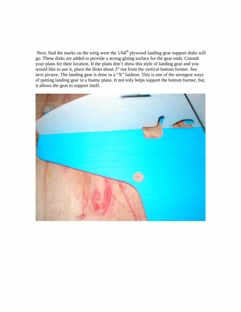
Next, find the marks on the wing were the 1/64th plywood landing gear support disks willgo. These disks are added to provide a strong gluing surface for the gear ends. Consultyour plans for their location. If the plans don’t show this style of landing gear and youwould like to use it, place the disks about 3” out from the vertical bottom former. Seenext picture. The landing gear is done in a “X” fashion. This is one of the strongest waysof putting landing gear in a foamy plane. It not only helps support the bottom former, but,it allows the gear to support itself.
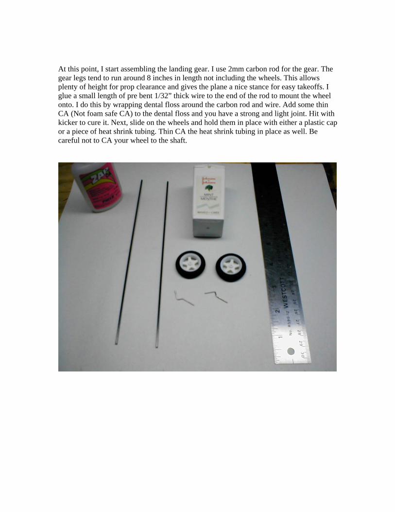
At this point, I start assembling the landing gear. I use 2mm carbon rod for the gear. Thegear legs tend to run around 8 inches in length not including the wheels. This allowsplenty of height for prop clearance and gives the plane a nice stance for easy takeoffs. Iglue a small length of pre bent 1/32” thick wire to the end of the rod to mount the wheelonto. I do this by wrapping dental floss around the carbon rod and wire. Add some thinCA (Not foam safe CA) to the dental floss and you have a strong and light joint. Hit withkicker to cure it. Next, slide on the wheels and hold them in place with either a plastic capor a piece of heat shrink tubing. Thin CA the heat shrink tubing in place as well. Becareful not to CA your wheel to the shaft.
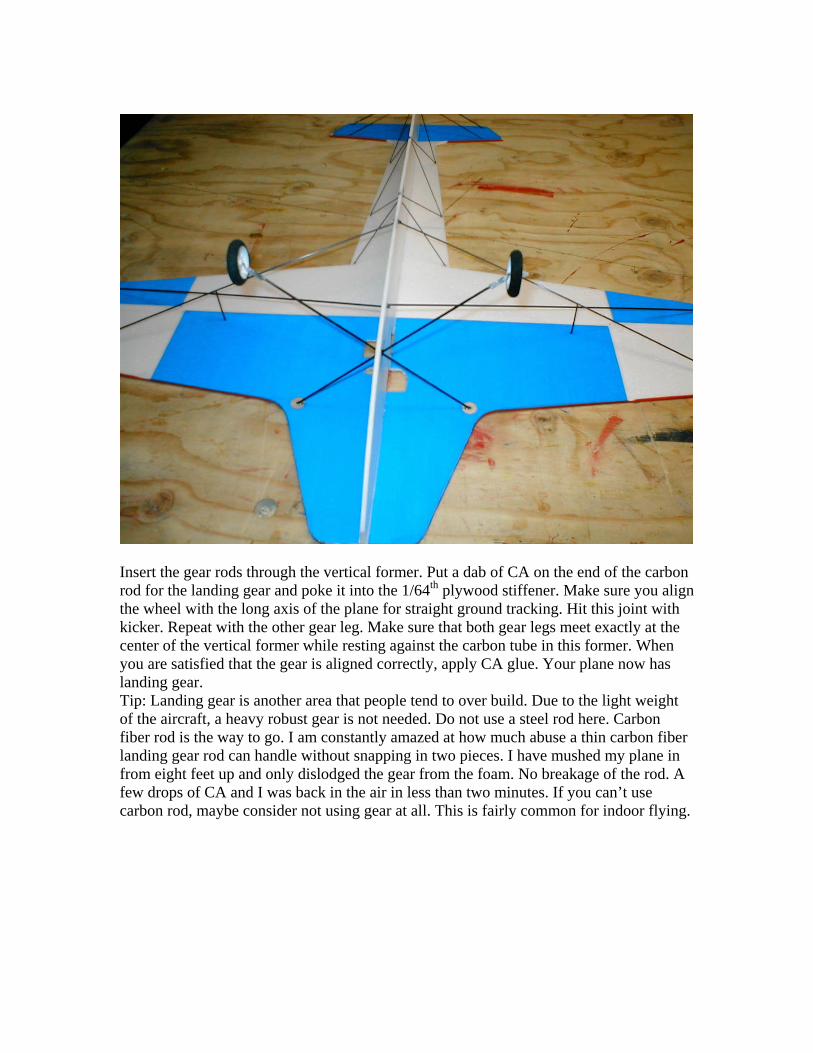
Insert the gear rods through the vertical former. Put a dab of CA on the end of the carbonrod for the landing gear and poke it into the 1/64th plywood stiffener. Make sure you alignthe wheel with the long axis of the plane for straight ground tracking. Hit this joint withkicker. Repeat with the other gear leg. Make sure that both gear legs meet exactly at thecenter of the vertical former while resting against the carbon tube in this former. Whenyou are satisfied that the gear is aligned correctly, apply CA glue. Your plane now haslanding gear.Tip: Landing gear is another area that people tend to over build. Due to the light weightof the aircraft, a heavy robust gear is not needed. Do not use a steel rod here. Carbonfiber rod is the way to go. I am constantly amazed at how much abuse a thin carbon fiberlanding gear rod can handle without snapping in two pieces. I have mushed my plane infrom eight feet up and only dislodged the gear from the foam. No breakage of the rod. Afew drops of CA and I was back in the air in less than two minutes. If you can’t usecarbon rod, maybe consider not using gear at all. This is fairly common for indoor flying.
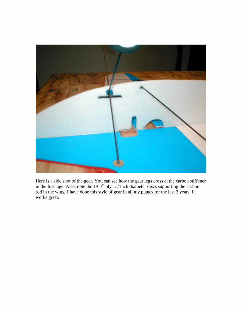
Here is a side shot of the gear. You can see how the gear legs cross at the carbon stiffenerin the fuselage. Also, note the 1/64th ply 1/2 inch diameter discs supporting the carbonrod in the wing. I have done this style of gear in all my planes for the last 3 years. Itworks great.
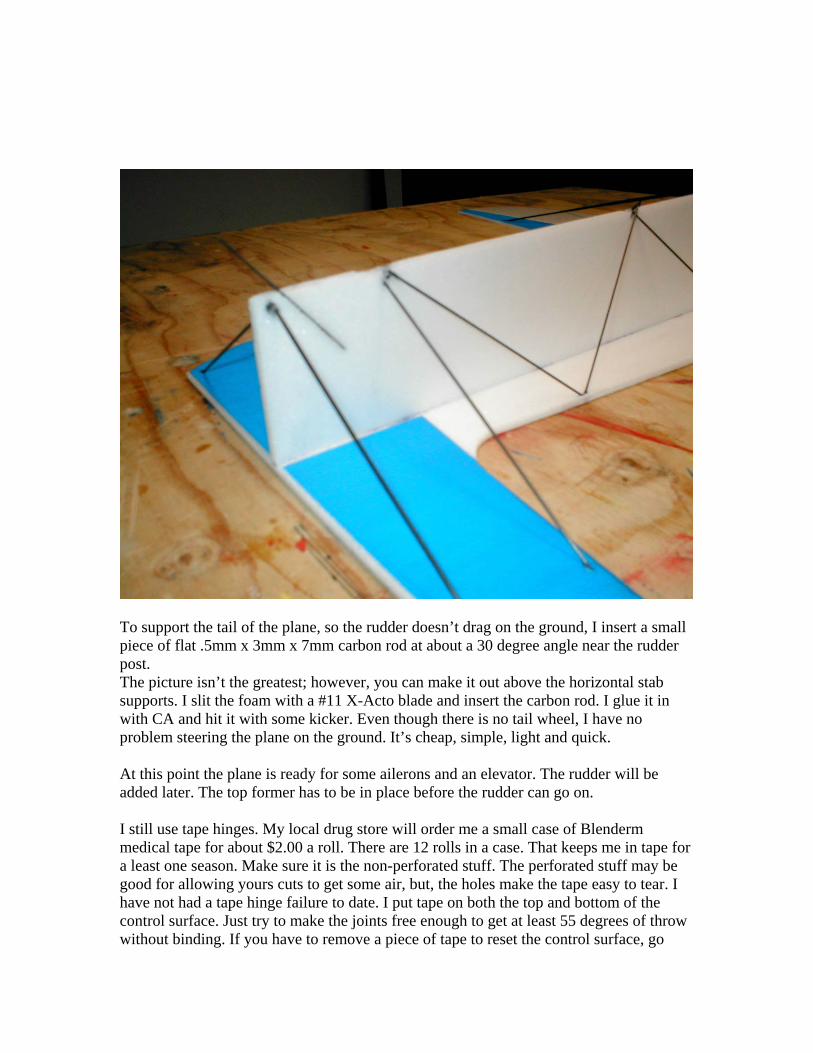
To support the tail of the plane, so the rudder doesn’t drag on the ground, I insert a smallpiece of flat .5mm x 3mm x 7mm carbon rod at about a 30 degree angle near the rudderpost.The picture isn’t the greatest; however, you can make it out above the horizontal stabsupports. I slit the foam with a #11 X-Acto blade and insert the carbon rod. I glue it inwith CA and hit it with some kicker. Even though there is no tail wheel, I have noproblem steering the plane on the ground. It’s cheap, simple, light and quick.
At this point the plane is ready for some ailerons and an elevator. The rudder will beadded later. The top former has to be in place before the rudder can go on.
I still use tape hinges. My local drug store will order me a small case of Blendermmedical tape for about $2.00 a roll. There are 12 rolls in a case. That keeps me in tape fora least one season. Make sure it is the non-perforated stuff. The perforated stuff may begood for allowing yours cuts to get some air, but, the holes make the tape easy to tear. Ihave not had a tape hinge failure to date. I put tape on both the top and bottom of thecontrol surface. Just try to make the joints free enough to get at least 55 degrees of throwwithout binding. If you have to remove a piece of tape to reset the control surface, go
ahead. This is better than having a stiff or binding control surface. Note: Removing thetape will often remove your nice paint job. Don’t be afraid to pull out your paint andtouch it up.
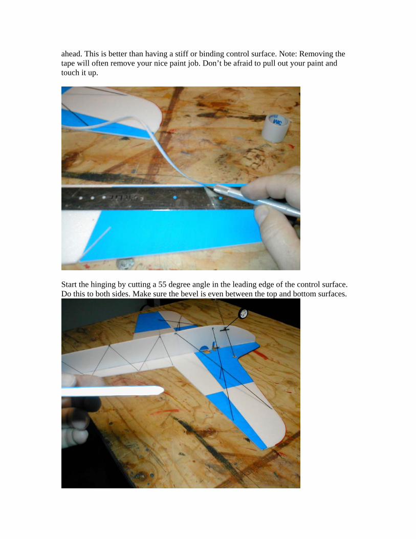
Start the hinging by cutting a 55 degree angle in the leading edge of the control surface.Do this to both sides. Make sure the bevel is even between the top and bottom surfaces.
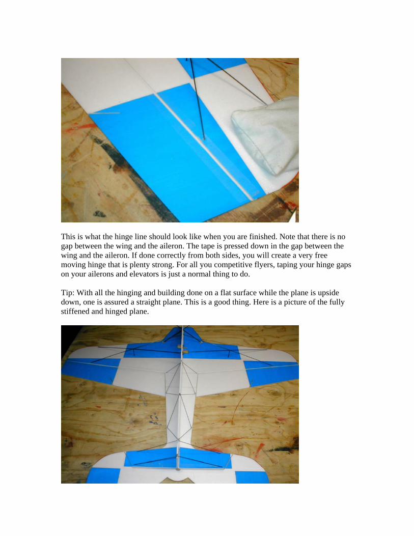
This is what the hinge line should look like when you are finished. Note that there is nogap between the wing and the aileron. The tape is pressed down in the gap between thewing and the aileron. If done correctly from both sides, you will create a very freemoving hinge that is plenty strong. For all you competitive flyers, taping your hinge gapson your ailerons and elevators is just a normal thing to do.
Tip: With all the hinging and building done on a flat surface while the plane is upsidedown, one is assured a straight plane. This is a good thing. Here is a picture of the fullystiffened and hinged plane.
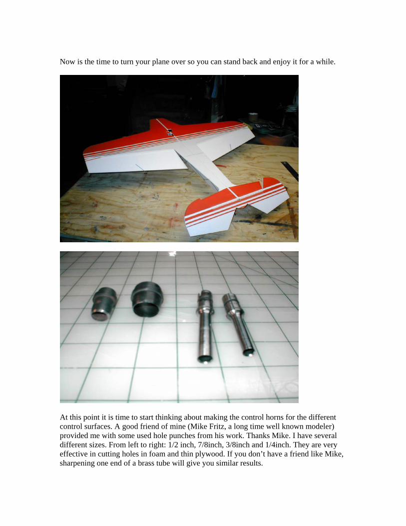
Now is the time to turn your plane over so you can stand back and enjoy it for a while.
At this point it is time to start thinking about making the control horns for the differentcontrol surfaces. A good friend of mine (Mike Fritz, a long time well known modeler)provided me with some used hole punches from his work. Thanks Mike. I have severaldifferent sizes. From left to right: 1/2 inch, 7/8inch, 3/8inch and 1/4inch. They are veryeffective in cutting holes in foam and thin plywood. If you don’t have a friend like Mike,sharpening one end of a brass tube will give you similar results.
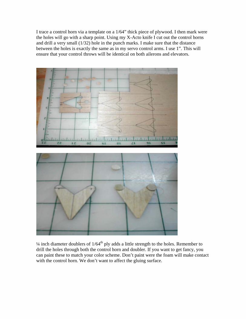
I trace a control horn via a template on a 1/64” thick piece of plywood. I then mark werethe holes will go with a sharp point. Using my X-Acto knife I cut out the control hornsand drill a very small (1/32) hole in the punch marks. I make sure that the distancebetween the holes is exactly the same as in my servo control arms. I use 1”. This willensure that your control throws will be identical on both ailerons and elevators.
¼ inch diameter doublers of 1/64th ply adds a little strength to the holes. Remember todrill the holes through both the control horn and doubler. If you want to get fancy, youcan paint these to match your color scheme. Don’t paint were the foam will make contactwith the control horn. We don’t want to affect the gluing surface.
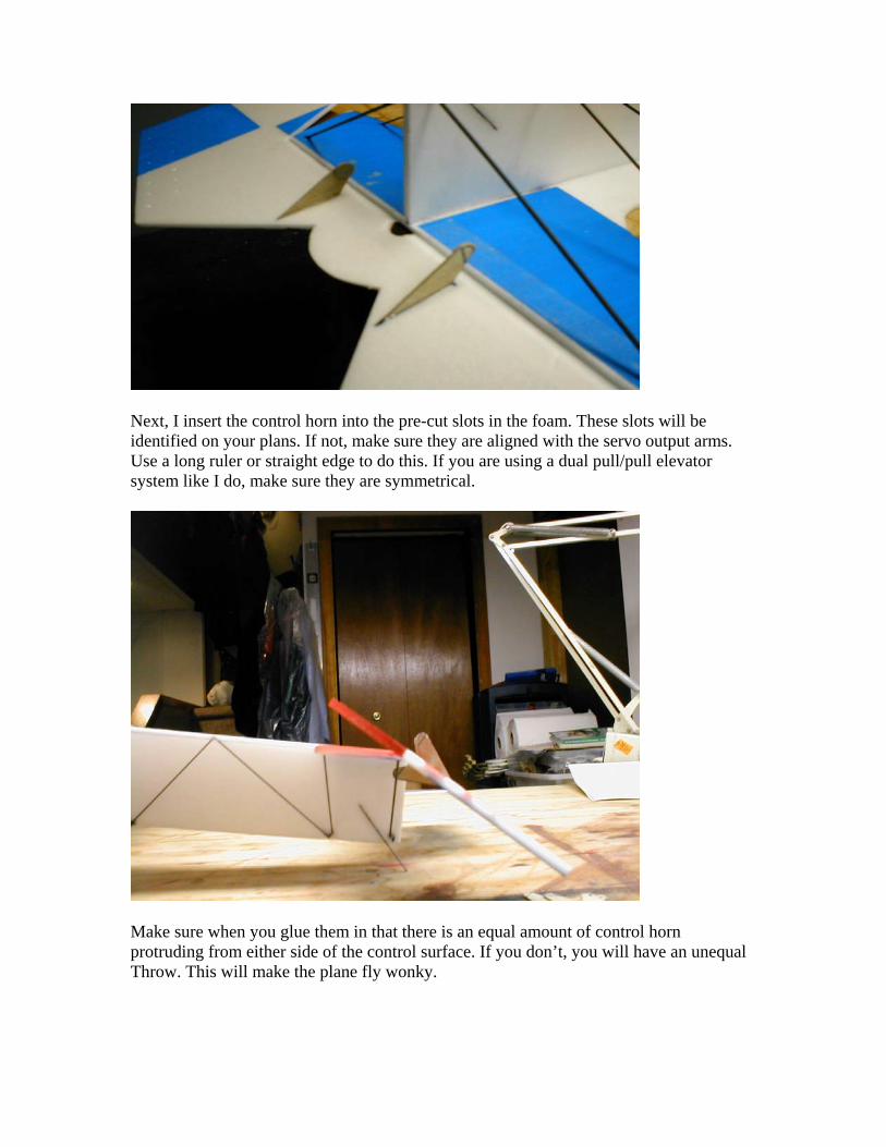
Next, I insert the control horn into the pre-cut slots in the foam. These slots will beidentified on your plans. If not, make sure they are aligned with the servo output arms.Use a long ruler or straight edge to do this. If you are using a dual pull/pull elevatorsystem like I do, make sure they are symmetrical.
Make sure when you glue them in that there is an equal amount of control hornprotruding from either side of the control surface. If you don’t, you will have an unequalThrow. This will make the plane fly wonky.
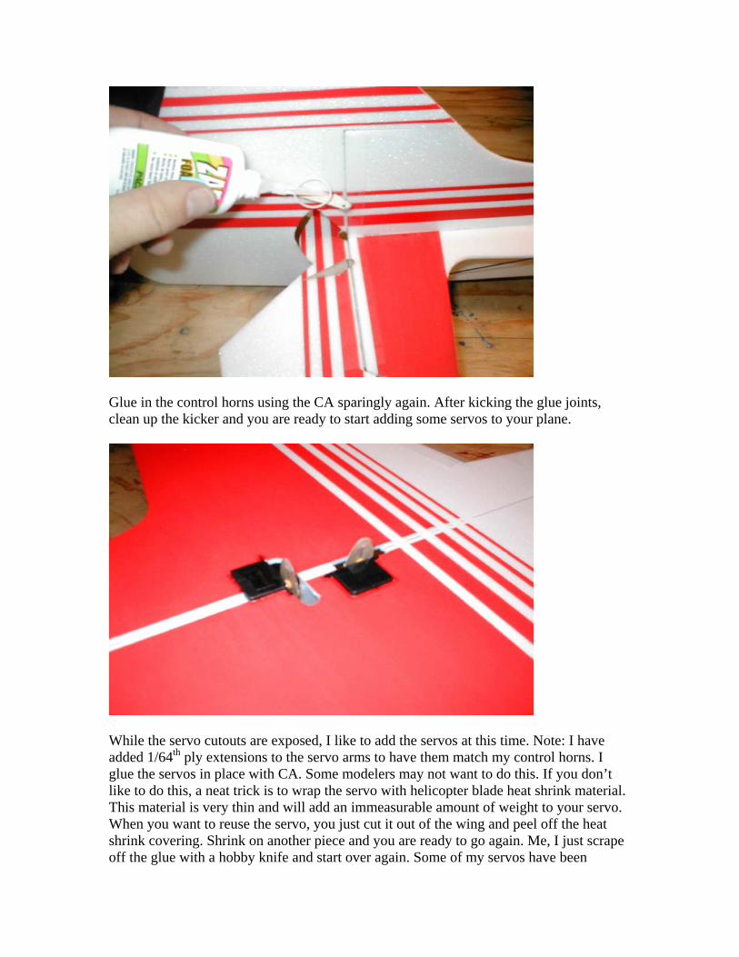
Glue in the control horns using the CA sparingly again. After kicking the glue joints,clean up the kicker and you are ready to start adding some servos to your plane.
While the servo cutouts are exposed, I like to add the servos at this time. Note: I haveadded 1/64th ply extensions to the servo arms to have them match my control horns. Iglue the servos in place with CA. Some modelers may not want to do this. If you don’tlike to do this, a neat trick is to wrap the servo with helicopter blade heat shrink material.This material is very thin and will add an immeasurable amount of weight to your servo.When you want to reuse the servo, you just cut it out of the wing and peel off the heatshrink covering. Shrink on another piece and you are ready to go again. Me, I just scrapeoff the glue with a hobby knife and start over again. Some of my servos have been
through six or seven planes and I haven’t noticed any difference from when they werenew. Whatever way you end up doing it, be careful to mount the servo as securely aspossible.
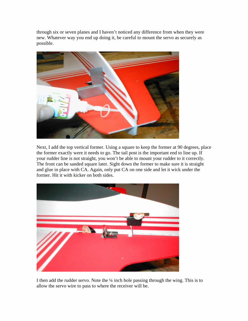
Next, I add the top vertical former. Using a square to keep the former at 90 degrees, placethe former exactly were it needs to go. The tail post is the important end to line up. Ifyour rudder line is not straight, you won’t be able to mount your rudder to it correctly.The front can be sanded square later. Sight down the former to make sure it is straightand glue in place with CA. Again, only put CA on one side and let it wick under theformer. Hit it with kicker on both sides.
I then add the rudder servo. Note the ¼ inch hole passing through the wing. This is toallow the servo wire to pass to where the receiver will be.
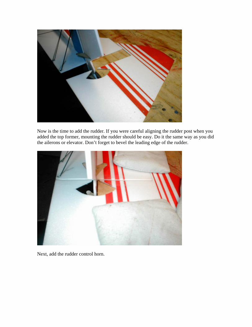
Now is the time to add the rudder. If you were careful aligning the rudder post when youadded the top former, mounting the rudder should be easy. Do it the same way as you didthe ailerons or elevator. Don’t forget to bevel the leading edge of the rudder.
Next, add the rudder control horn.
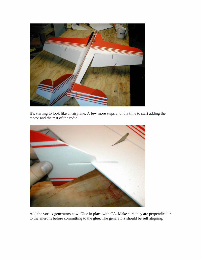
It’s starting to look like an airplane. A few more steps and it is time to start adding themotor and the rest of the radio.
Add the vortex generators now. Glue in place with CA. Make sure they are perpendicularto the ailerons before committing to the glue. The generators should be self aligning.
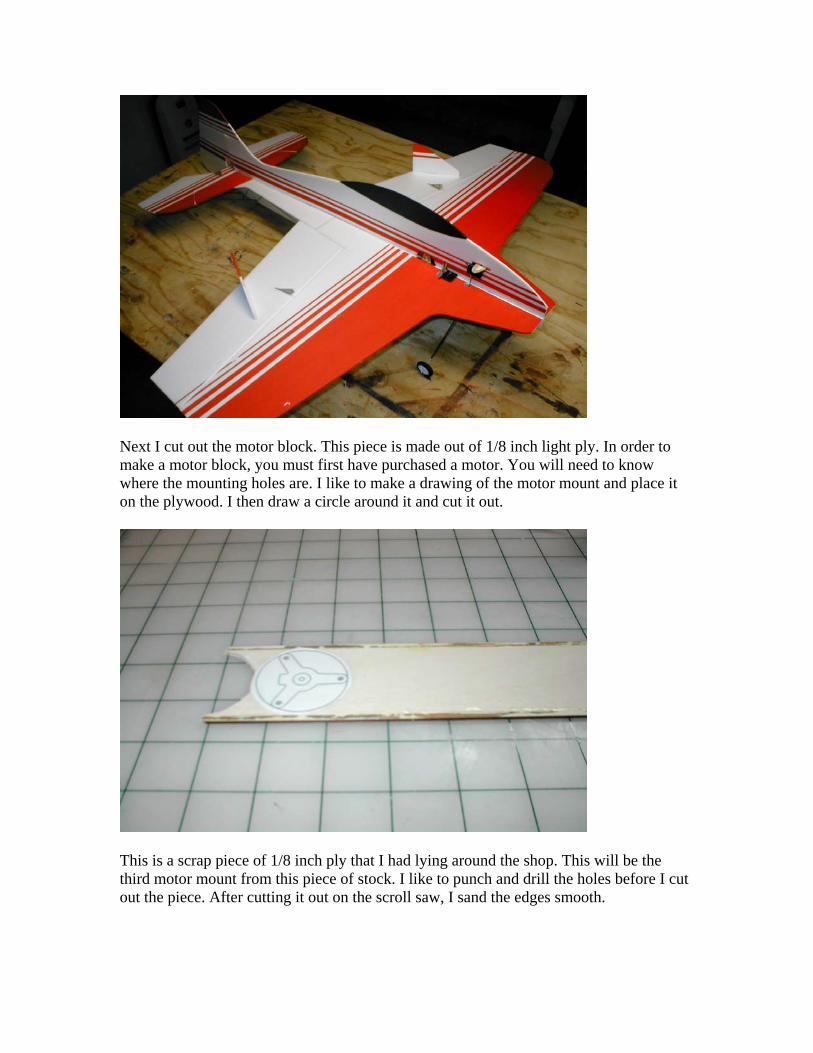
Next I cut out the motor block. This piece is made out of 1/8 inch light ply. In order tomake a motor block, you must first have purchased a motor. You will need to knowwhere the mounting holes are. I like to make a drawing of the motor mount and place iton the plywood. I then draw a circle around it and cut it out.
This is a scrap piece of 1/8 inch ply that I had lying around the shop. This will be thethird motor mount from this piece of stock. I like to punch and drill the holes before I cutout the piece. After cutting it out on the scroll saw, I sand the edges smooth.
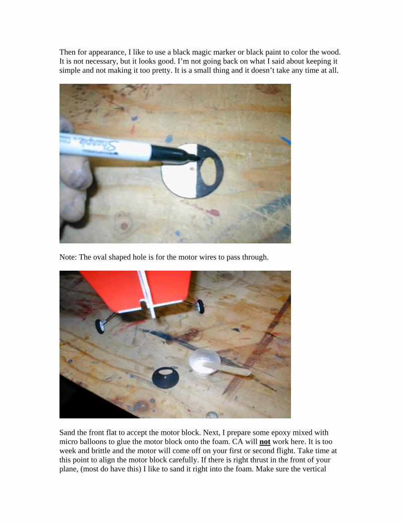
Then for appearance, I like to use a black magic marker or black paint to color the wood.It is not necessary, but it looks good. I’m not going back on what I said about keeping itsimple and not making it too pretty. It is a small thing and it doesn’t take any time at all.
Note: The oval shaped hole is for the motor wires to pass through.
Sand the front flat to accept the motor block. Next, I prepare some epoxy mixed withmicro balloons to glue the motor block onto the foam. CA will not work here. It is tooweek and brittle and the motor will come off on your first or second flight. Take time atthis point to align the motor block carefully. If there is right thrust in the front of yourplane, (most do have this) I like to sand it right into the foam. Make sure the vertical
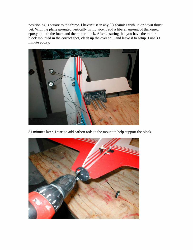
positioning is square to the frame. I haven’t seen any 3D foamies with up or down thrustyet. With the plane mounted vertically in my vice, I add a liberal amount of thickenedepoxy to both the foam and the motor block. After ensuring that you have the motorblock mounted in the correct spot, clean up the over spill and leave it to setup. I use 30minute epoxy.
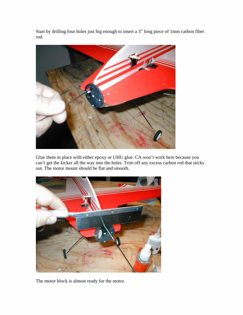
31 minutes later, I start to add carbon rods to the mount to help support the block.
Start by drilling four holes just big enough to insert a 3” long piece of 1mm carbon fiberrod.
Glue them in place with either epoxy or UHU glue. CA won’t work here because youcan’t get the kicker all the way into the holes. Trim off any excess carbon rod that sticksout. The motor mount should be flat and smooth.
The motor block is almost ready for the motor.
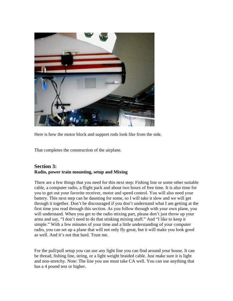
Here is how the motor block and support rods look like from the side.
That completes the construction of the airplane.
Section 3:Radio, power train mounting, setup and Mixing
There are a few things that you need for this next step: Fishing line or some other suitablecable, a computer radio, a flight pack and about two hours of free time. It is also time foryou to get out your favorite receiver, motor and speed control. You will also need yourbattery. This next step can be daunting for some, so I will take it slow and we will getthrough it together. Don’t be discouraged if you don’t understand what I am getting at thefirst time you read through this section. As you follow through with your own plane, youwill understand. When you get to the radio mixing part, please don’t just throw up yourarms and say, “I don’t need to do that stinking mixing stuff.” And “I like to keep itsimple.” With a few minutes of your time and a little understanding of your computerradio, you can set up a plane that will not only fly great, but it will make you look goodas well. And it’s not that hard. Trust me.
For the pull/pull setup you can use any light line you can find around your house. It canbe thread, fishing line, string, or a light weight braided cable. Just make sure it is lightand non-stretchy. Note: The line you use must take CA well. You can use anything thathas a 4 pound test or higher.

It doesn’t matter what control surface you start with. Tie a knot in one end of your fishingline and thread it through one eye of the control horn. Hit it with thin CA and kicker tohold it in place.Feed the line up to one of the holes in the servo arm from the bottom and pass it through.Run the line across the top of the servo arm and down through the opposite hole.
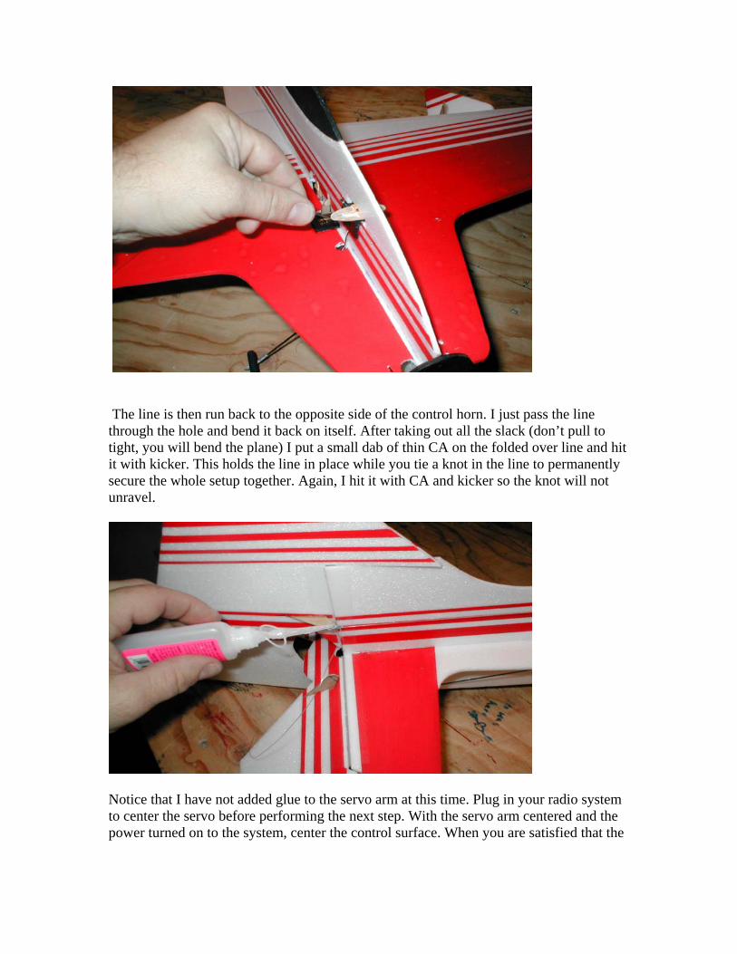
The line is then run back to the opposite side of the control horn. I just pass the linethrough the hole and bend it back on itself. After taking out all the slack (don’t pull totight, you will bend the plane) I put a small dab of thin CA on the folded over line and hitit with kicker. This holds the line in place while you tie a knot in the line to permanentlysecure the whole setup together. Again, I hit it with CA and kicker so the knot will notunravel.
Notice that I have not added glue to the servo arm at this time. Plug in your radio systemto center the servo before performing the next step. With the servo arm centered and thepower turned on to the system, center the control surface. When you are satisfied that the
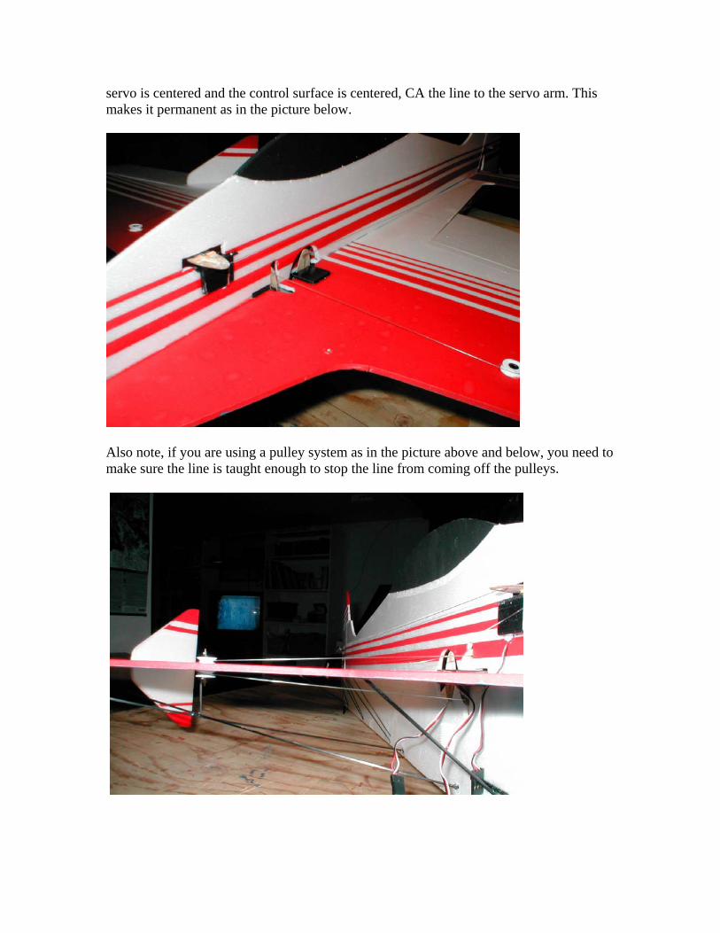
servo is centered and the control surface is centered, CA the line to the servo arm. Thismakes it permanent as in the picture below.
Also note, if you are using a pulley system as in the picture above and below, you need tomake sure the line is taught enough to stop the line from coming off the pulleys.
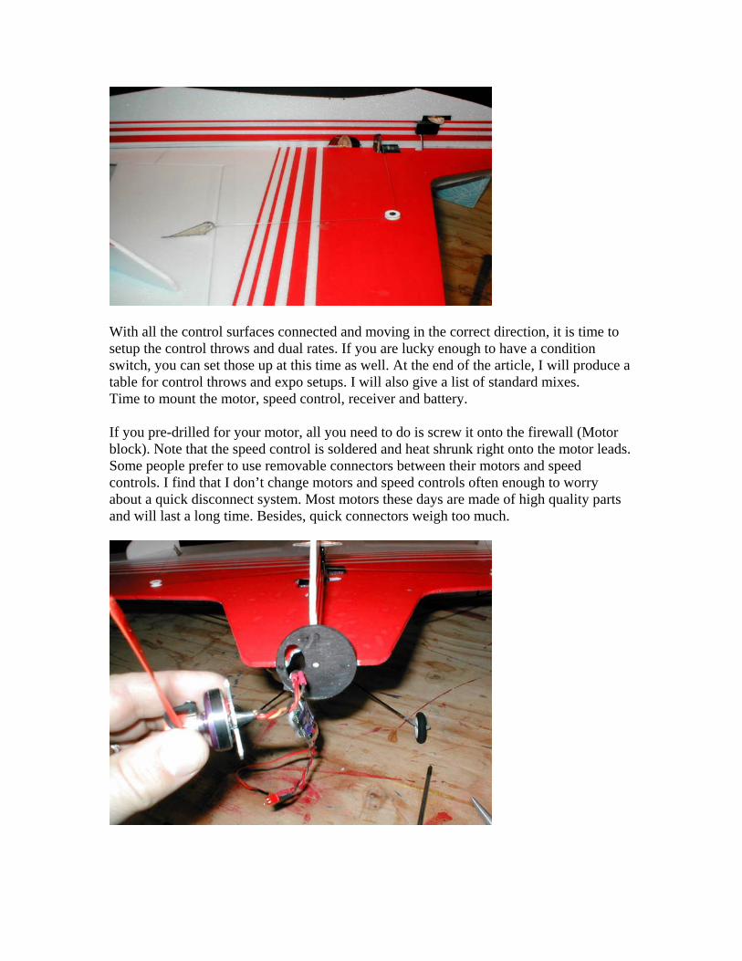
With all the control surfaces connected and moving in the correct direction, it is time tosetup the control throws and dual rates. If you are lucky enough to have a conditionswitch, you can set those up at this time as well. At the end of the article, I will produce atable for control throws and expo setups. I will also give a list of standard mixes.Time to mount the motor, speed control, receiver and battery.
If you pre-drilled for your motor, all you need to do is screw it onto the firewall (Motorblock). Note that the speed control is soldered and heat shrunk right onto the motor leads.Some people prefer to use removable connectors between their motors and speedcontrols. I find that I don’t change motors and speed controls often enough to worryabout a quick disconnect system. Most motors these days are made of high quality partsand will last a long time. Besides, quick connectors weigh too much.
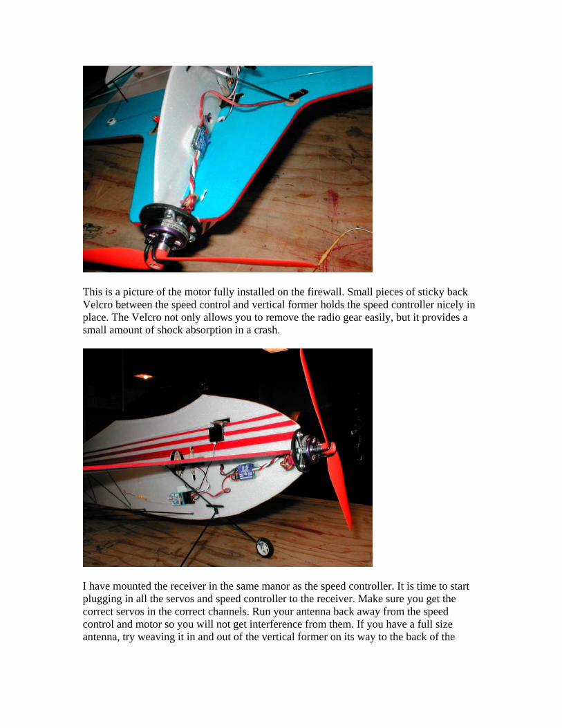
This is a picture of the motor fully installed on the firewall. Small pieces of sticky backVelcro between the speed control and vertical former holds the speed controller nicely inplace. The Velcro not only allows you to remove the radio gear easily, but it provides asmall amount of shock absorption in a crash.
I have mounted the receiver in the same manor as the speed controller. It is time to startplugging in all the servos and speed controller to the receiver. Make sure you get thecorrect servos in the correct channels. Run your antenna back away from the speedcontrol and motor so you will not get interference from them. If you have a full sizeantenna, try weaving it in and out of the vertical former on its way to the back of the
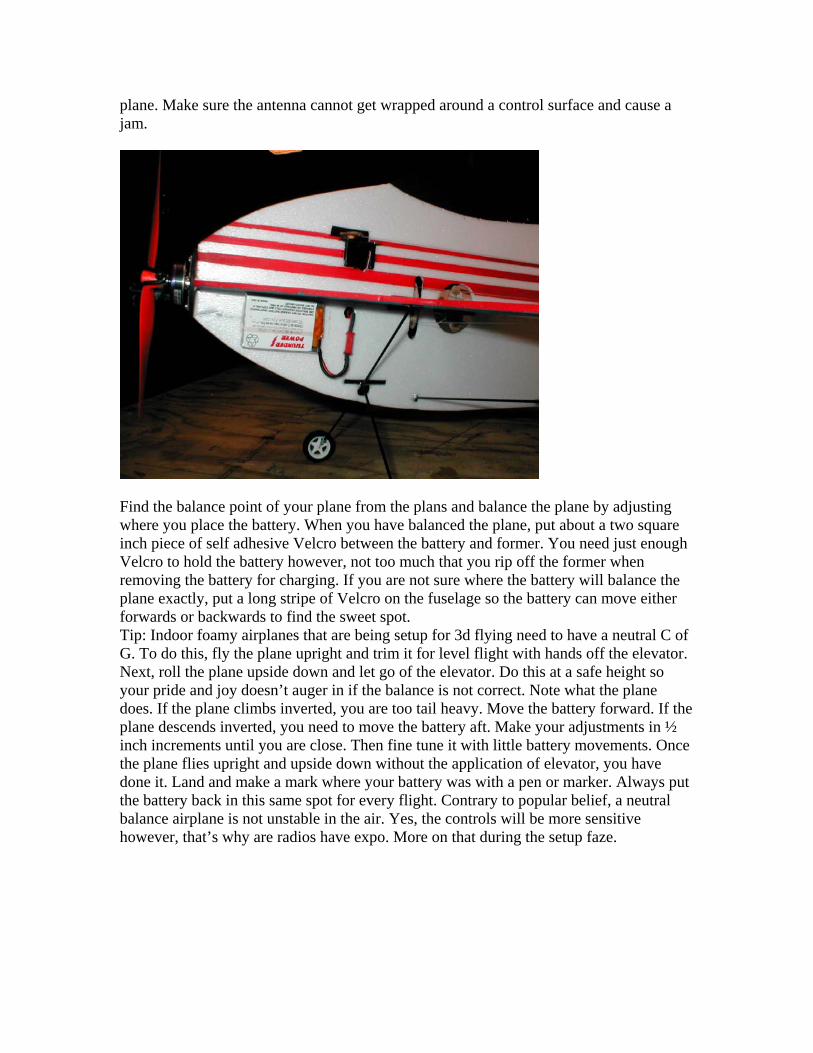
plane. Make sure the antenna cannot get wrapped around a control surface and cause ajam.
Find the balance point of your plane from the plans and balance the plane by adjustingwhere you place the battery. When you have balanced the plane, put about a two squareinch piece of self adhesive Velcro between the battery and former. You need just enoughVelcro to hold the battery however, not too much that you rip off the former whenremoving the battery for charging. If you are not sure where the battery will balance theplane exactly, put a long stripe of Velcro on the fuselage so the battery can move eitherforwards or backwards to find the sweet spot.Tip: Indoor foamy airplanes that are being setup for 3d flying need to have a neutral C ofG. To do this, fly the plane upright and trim it for level flight with hands off the elevator.Next, roll the plane upside down and let go of the elevator. Do this at a safe height soyour pride and joy doesn’t auger in if the balance is not correct. Note what the planedoes. If the plane climbs inverted, you are too tail heavy. Move the battery forward. If theplane descends inverted, you need to move the battery aft. Make your adjustments in ½inch increments until you are close. Then fine tune it with little battery movements. Oncethe plane flies upright and upside down without the application of elevator, you havedone it. Land and make a mark where your battery was with a pen or marker. Always putthe battery back in this same spot for every flight. Contrary to popular belief, a neutralbalance airplane is not unstable in the air. Yes, the controls will be more sensitivehowever, that’s why are radios have expo. More on that during the setup faze.
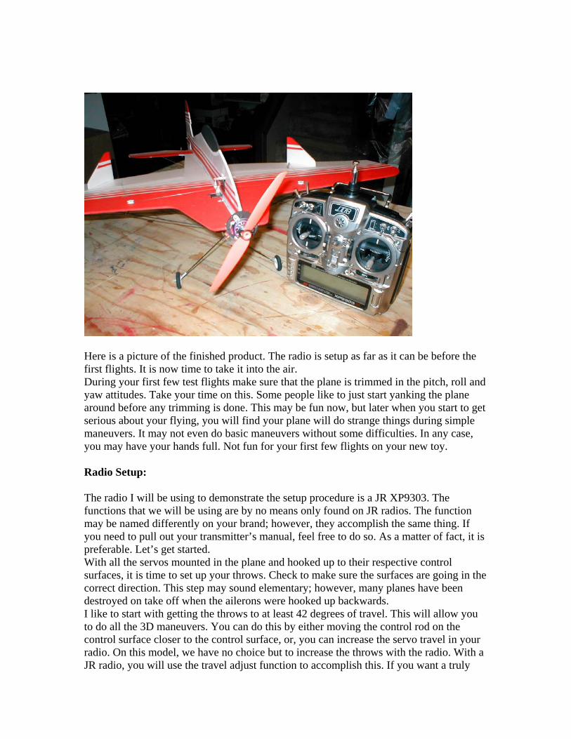
Here is a picture of the finished product. The radio is setup as far as it can be before thefirst flights. It is now time to take it into the air.During your first few test flights make sure that the plane is trimmed in the pitch, roll andyaw attitudes. Take your time on this. Some people like to just start yanking the planearound before any trimming is done. This may be fun now, but later when you start to getserious about your flying, you will find your plane will do strange things during simplemaneuvers. It may not even do basic maneuvers without some difficulties. In any case,you may have your hands full. Not fun for your first few flights on your new toy.
Radio Setup:
The radio I will be using to demonstrate the setup procedure is a JR XP9303. Thefunctions that we will be using are by no means only found on JR radios. The functionmay be named differently on your brand; however, they accomplish the same thing. Ifyou need to pull out your transmitter’s manual, feel free to do so. As a matter of fact, it ispreferable. Let’s get started.With all the servos mounted in the plane and hooked up to their respective controlsurfaces, it is time to set up your throws. Check to make sure the surfaces are going in thecorrect direction. This step may sound elementary; however, many planes have beendestroyed on take off when the ailerons were hooked up backwards.I like to start with getting the throws to at least 42 degrees of travel. This will allow youto do all the 3D maneuvers. You can do this by either moving the control rod on thecontrol surface closer to the control surface, or, you can increase the servo travel in yourradio. On this model, we have no choice but to increase the throws with the radio. With aJR radio, you will use the travel adjust function to accomplish this. If you want a truly

superb flying model, it is also imperative to make sure your ailerons travel equal amountsin both directions, up and down. You must also make sure that the ailerons travel in equalamounts in relation to each other. If you don’t, the plane will not do an axial roll. With atwo aileron setup, this is fairly easy to accomplish using travel adjust, and Dual rates. Ifyou are using one aileron servo like our subject model, you will have to take care in yourinitial setup. The holes in both the servo control arm and control horn must be of equaldistance between them. Also, the control horn must be centered equally in the controlsurface. If the distance between the hinge line and the hole in the control horn is not equaltop and bottom, the throws will not be symmetrical. If you have a split elevator, it is alsoimperative that the throws are equal in both the up and down direction. If one elevator ispulling more than the other, you will create a roll when all you want is pitch. This is onereason why loops can become corkscrew shaped.
Below are a few devices that will help you manage your control throws.
The first method is using the CRC Products angle gage. It is probably not the best tool touse on foamies due to its weight. It will bend the 3mm foam and give you an inaccuratereading. However, see the picture on next page for its use.

Just clip the CRC gage on the back of the neutral control surface, center the needle to“0”, and deflect control surface to the desired amount.
The ruler method is probably the most common to use as most people already have one athome.
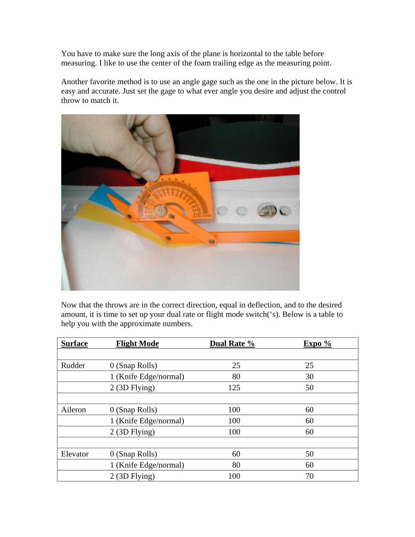
You have to make sure the long axis of the plane is horizontal to the table beforemeasuring. I like to use the center of the foam trailing edge as the measuring point.
Another favorite method is to use an angle gage such as the one in the picture below. It iseasy and accurate. Just set the gage to what ever angle you desire and adjust the controlthrow to match it.
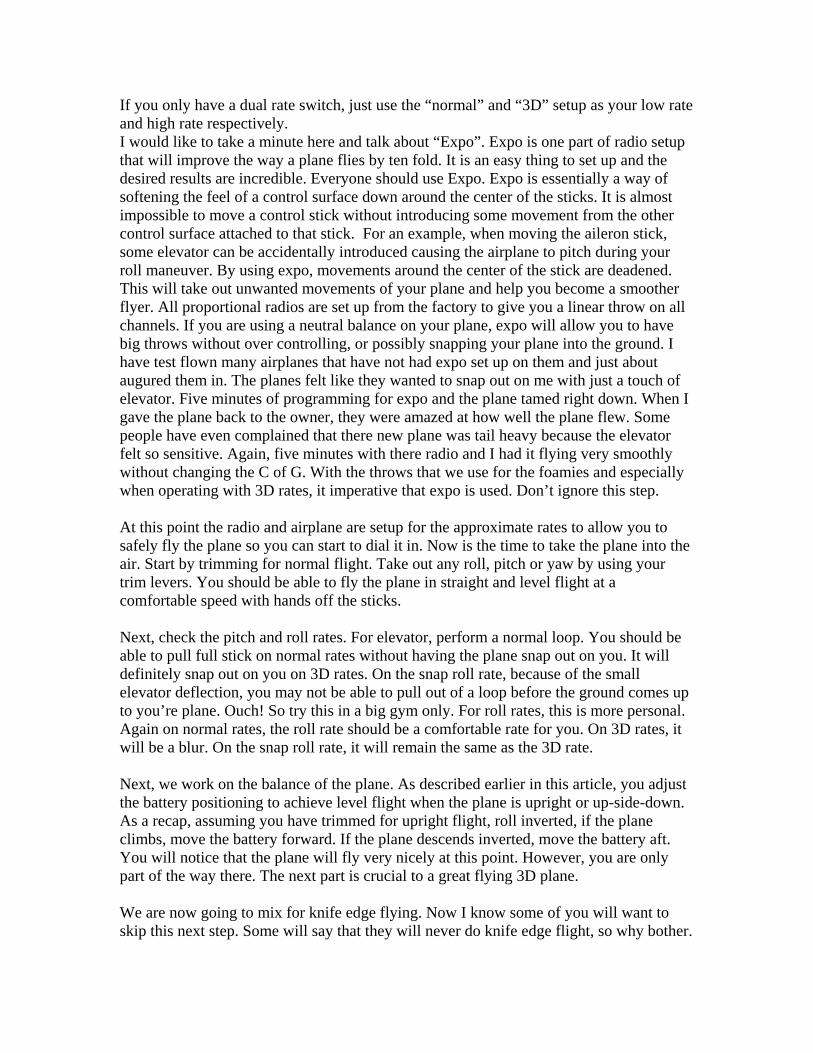
Now that the throws are in the correct direction, equal in deflection, and to the desiredamount, it is time to set up your dual rate or flight mode switch(‘s). Below is a table tohelp you with the approximate numbers.
Surface Flight Mode Dual Rate % Expo %
Rudder 0 (Snap Rolls) 25 251 (Knife Edge/normal) 80 302 (3D Flying) 125 50
Aileron 0 (Snap Rolls) 100 601 (Knife Edge/normal) 100 602 (3D Flying) 100 60
Elevator 0 (Snap Rolls) 60 501 (Knife Edge/normal) 80 602 (3D Flying) 100 70
If you only have a dual rate switch, just use the “normal” and “3D” setup as your low rateand high rate respectively.I would like to take a minute here and talk about “Expo”. Expo is one part of radio setupthat will improve the way a plane flies by ten fold. It is an easy thing to set up and thedesired results are incredible. Everyone should use Expo. Expo is essentially a way ofsoftening the feel of a control surface down around the center of the sticks. It is almostimpossible to move a control stick without introducing some movement from the othercontrol surface attached to that stick. For an example, when moving the aileron stick,some elevator can be accidentally introduced causing the airplane to pitch during yourroll maneuver. By using expo, movements around the center of the stick are deadened.This will take out unwanted movements of your plane and help you become a smootherflyer. All proportional radios are set up from the factory to give you a linear throw on allchannels. If you are using a neutral balance on your plane, expo will allow you to havebig throws without over controlling, or possibly snapping your plane into the ground. Ihave test flown many airplanes that have not had expo set up on them and just aboutaugured them in. The planes felt like they wanted to snap out on me with just a touch ofelevator. Five minutes of programming for expo and the plane tamed right down. When Igave the plane back to the owner, they were amazed at how well the plane flew. Somepeople have even complained that there new plane was tail heavy because the elevatorfelt so sensitive. Again, five minutes with there radio and I had it flying very smoothlywithout changing the C of G. With the throws that we use for the foamies and especiallywhen operating with 3D rates, it imperative that expo is used. Don’t ignore this step.
At this point the radio and airplane are setup for the approximate rates to allow you tosafely fly the plane so you can start to dial it in. Now is the time to take the plane into theair. Start by trimming for normal flight. Take out any roll, pitch or yaw by using yourtrim levers. You should be able to fly the plane in straight and level flight at acomfortable speed with hands off the sticks.
Next, check the pitch and roll rates. For elevator, perform a normal loop. You should beable to pull full stick on normal rates without having the plane snap out on you. It willdefinitely snap out on you on 3D rates. On the snap roll rate, because of the smallelevator deflection, you may not be able to pull out of a loop before the ground comes upto you’re plane. Ouch! So try this in a big gym only. For roll rates, this is more personal.Again on normal rates, the roll rate should be a comfortable rate for you. On 3D rates, itwill be a blur. On the snap roll rate, it will remain the same as the 3D rate.
Next, we work on the balance of the plane. As described earlier in this article, you adjustthe battery positioning to achieve level flight when the plane is upright or up-side-down.As a recap, assuming you have trimmed for upright flight, roll inverted, if the planeclimbs, move the battery forward. If the plane descends inverted, move the battery aft.You will notice that the plane will fly very nicely at this point. However, you are onlypart of the way there. The next part is crucial to a great flying 3D plane.
We are now going to mix for knife edge flying. Now I know some of you will want toskip this next step. Some will say that they will never do knife edge flight, so why bother.
If you are planning on doing a simple rudder turn, you will want to do this mix. If youwant to do an axial or slow roll, you will want to do this mix. And lastly, if you want todo any maneuver that requires the use of rudder, including take offs, you will want to dothis mix. If you are not capable of doing knife edge flight, I recommend that you findsomeone that is. Get him or her to fly your plane in this next faze of trimming. No planeout there can be flown in knife edge flight without some sort of mixing of both the rudderto elevator and rudder to ailerons. Most planes either pull to gear or canopy while in knifeedge flight. They also will have a perverse or adverse roll tendency while in knife edgeflight. Perverse roll is the condition where the plane will want to roll in the direction thatthe rudder is applied. (i.e.) Applying right rudder while in knife edge flight will cause theplane to roll to the right. Were Adverse roll is where the plane will roll opposite to therudder applied in knife edge flight. (i.e.) Applying right rudder while in knife edge flightwill cause the plane to roll to the left. All the foamies that I have flown pull to the gearand have had proverse roll. In other words, the plane tucks under and wants to roll out ofthe knife edge flight. I must note here that when putting the plane in knife edge flight,you should not use the elevator or ailerons to right it. We want to see what the plane isdoing on its own. I first mix the rudder to elevator. Since my planes pull to gear while inknife edge flight, I set them up with about 5% up elevator mixed to the rudder. I then goairborne again, roll it into knife edge flight and see what it does. If it flies straight inpitch, without pulling to gear or canopy, I move on to the Rudder to aileron mix. If itdoesn’t fly straight in pitch, I add more mixing or take some away until it does flystraight. You should fly the plane in knife edge flight for quite a few passes to make sureyou have the mixing done correctly. Don’t forget to do this in both directions. My planestend to have proverse roll while in knife edge flight. They want to roll themselves out orback to level flight. I start again with about 5% opposite aileron to rudder mix. Thismeans that if I am using right rudder, the ailerons should roll the plane to the left. Theright aileron should go down about 5% and the left aileron will go up about 5%. Workthis over and over again, fine tuning your mixing. You may even have to go back to yourrudder to elevator mixing and re-adjust as you get closer to pure knife edge flight. Whenyou finally get the plane dialed in, you should be able to fly knife edge flight from oneend of the gym to the other just by using rudder only. A note here: most radios now havemixing with a point curve. This means that small rudder applications require smallmixing values. Larger rudder applications require a larger amount of mixing. This is notalways a linear relationship. Therefore, radios can be set up with a non-linear curve.Much like a throttle curve. At this point you will probably notice that flat rudder turns are now a breeze to do. Noaileron or elevator application should be required. Not only does this look cool, it is anecessary maneuver for indoor flying. See, I told you it wasn’t that difficult. Try someknife edge outside 360’s and some 4 point rolls. You will find that it is relatively easy todo these maneuvers. As an added bonus, you should notice that stall turns have become easer to do as well.The plane won’t roll off at the top and the down lines should be straight without tuckingunder or pulling out prematurely. This is the minimum amount of mixing that should bedone on all your airplanes. All the previous mixes are required and some would considerthem mandatory. After this, the other mixes are optional. They will improve certain partsof your flying but, not all. If you want to, you can stop reading here. Although; the other
mixes make for interesting reading and may help you remove an unwanted flightcharacteristic from your favorite plane.
Up to this point, all mixing will be “turned on” at all times. In other words, there is no on-off switch or lever for activating them. Some mixes may only be needed during certainaspects of flight such a stall turns, down lines, snap rolls etc. Therefore, they need to beset up with an on-off switch. They can be activated by your flight mode switch or even acontrol stick.One example that uses this technique is the snap roll setup. A friend of mine likes to mixelevator to ailerons and rudder simultaneously. He does this by using his condition switchto activate his elevator stick as the on-off switch. Sound a little confusing? Fear not, hereis how it works. A condition is set up for snap rolls on his flight mode lever. Whenselected, the flight mode switch uses the elevator stick as the on, off switch. Without thiscondition, you would enter a spin normally by moving the elevator, rudder and aileronssticks to their full travel at near the same time. We call this “burying the sticks in thecorners” However, this does not always produce a pure snap roll. When doing a correctsnap roll, especially when competing, the judges want to see the nose of the airplanebreak the plane of flight slightly before the aircraft actually snaps. If they don’t see thebreak, most judges will think the plane just did a fast barrel or aileron roll, not a snap roll.This will score you a big fat “0”. To do the maneuver correctly, the elevator must cometo the stop slightly before the rudder and aileron sticks do. This will cause the plane tostall first, allowing the nose of the plane to break the plane of flight before snapping.Timing this can be very tricky and hard to do. If your timing is not perfect, the snap rollwill not be perfect either. My friend beats the odds by building in a delay in the rudderand aileron deflection by setting up his radio to not put in the rudder and aileron until theelevator has reached 95% of its travel. Even though the sticks are fully moved on therudder, ailerons and elevator at the same time, the rudder and ailerons won’t move untilthe elevator reaches its stop. You simply move all the sticks at the same time and theelevator stick provides the timing. Don’t forget to turn it off when normal flying.
The next mix is one that will need to be turned on and off as well. Although I don’t use itmyself, I do know of a few guys that use it with great results. Try mixing throttle torudder. When full throttle is used, especially with high angles of attacks, right rudder isrequired to control the yaw due to slip stream. This is assuming you have not put rightthrust in your motor or there is not enough right thrust. Some people feel that 3D flying iseasier with no right thrust at all. The Slipstream yaw will be removed by the use ofmixing throttle to rudder. As an example, assume you have just pulled up into a verticalup-line. In this attitude, after a short time, the nose of the airplane will have a tendency toyaw to the left. Right rudder will have to be manually applied to counteract this tendency.With the mix of throttle to rudder, you should not have to touch the rudder in the climb.This will limit or eliminate any tendency of your plane to wiggle its bum in up-lines asyou search for the perfect amount of right rudder. However, in straight and level flight, ifyou pinned the throttle, you won’t need to control slip stream yaw. Therefore, it can beturned off.Another throttle mix that is useful is the mixing of throttle to elevator. Again when doingvertical maneuvers, such as long down lines, the plane will have a tendency to pull out of
the dive. By mixing down elevator to low or idle throttle, you can make the plane travelin a perfectly straight down line. Again, use this mix with an on-off switch.In all cases of mixing channels together, start with small percentages and work inincreasing increments from there.Of course, with computer radios becoming more sophisticated and easier to program, youcan do any mixing your mind can dream up. So don’t be afraid to get into this part ofyour radio. The results will be worth the learning curve. Now go out and show the worldhow it’s done.