by mining lands section - ontario
TRANSCRIPT
i l l l l l l l l
l l
a.eses HORNE 010
AIRBORNE GEOPHYSICAL SURVEY OPERATIONS REPORT
DAWSON ROAD LOTS
ON BEHALF OF
JALNA RESOURCES LIMITED
Suite A17, Block A n C r C l V P D 6120 - 2nd Street S.E. K C^- CI v fc "
Calgary, Alberta m T 2H 2L8 JUL O 9 1985
BY MINING LANDS SECTION
GEOTECH LTD.Unit 20
101 Amber Street Markham, Ontario
L3R 3B2ll Approved on behalf of Geotech Ltd.
l
l
l
l
Paul WesslerVice President and General Manager
l l l l l l l l l l l l l l l l l l l
52AiaSWM58 8.8265 HORNE
Pagel.O Abstract 2
2.0 Survey Specifications 3
3.0 Data Compilation 7
4.0 Survey Instrumentation 9
5.0 Ope rational Personnel 10
6.0 F i t; l d L o g i s t i c s 11
7.0 Qualifications of Report Writer 16
Append ices:
A. Survey Location MapB . C l a i jn Blocks CoveredC . MOT AH-100 FormD. Instrument Specification Sheets
Maps :
4 HEM Mapsl Magnetic Contour Mapl VI.F Map
010C
l l l l l l l l l l l l l l l l l l l
ABSTRACT
l.O ABSTRACT
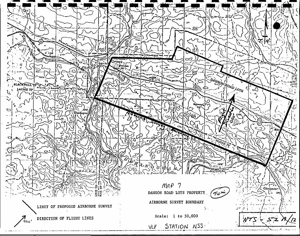
This report covers a combined HEM, Magnetometer and VLF Airborne Geophysical Survey over the Dawson Road Lots property shown on the location map included in this report - NTS Sheet 52A/12.
The survey was flown for Jalna Resources Limited {Jalna) by Geotech Ltd. (Geotech) between December 28, 1984 and January 25, 1985. The field crew mobilized from Markham to Thunder Bay on December 28, 1984. The base of operations for the survey was Shabaqua, Ontario. Fuel was trucked by Geotech from Thunder Bay to the base at the Timberland Motel. The installation was completed and the first test flight made on January 2, 1985; however, severe weather, instrumentation failures, especially with the magnetometer, and pilot inability to handle the HEM bird hampered the efficiency of the survey. A brief summary of the field problems is contained within this report. Severe cold {-40 C) hampered the operation of the data acquisition system throughout the survey. Visual navigation was used with flight path recovery done using a video system. Examples of the analog presentation are contained in this report, as well as instrument and survey specifications.
Data compilation for the survey was done at the facilities of Data Plotting Limited. Difficulty was encountered in loading the survey magnetic tapes onto the main frame computer. It j s felt that large temperature differentials between the recording and reading environments may account for some of the tape loading problems observed at Data Plotting Ltd. and numerous software routines had to be written in order to handle the UDAS survey format. Heavy work load at Data Plotting has necessitated the long turn-around time for final map presentation.
Additional information may be obtained by contacting Geotech.
l l l
SURVEY SPECIFICATIONS
l l l l l l l l l l l l l
2.0 SURVEY SPECIFICATIONS
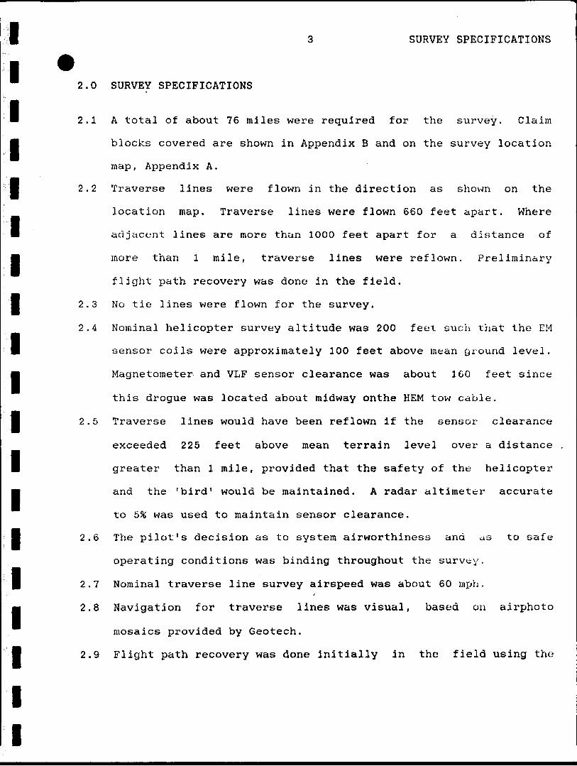
2.1 A total of about 76 miles were required for the survey. Claim
M blocks covered are shown in Appendix B and on the survey location
map. Appendix A.
l 2.2 Traverse lines were flown in the direction as shown on the
location map. Traverse lines were flown 660 feet apart. Where
adjacent lines are more than 1000 feet apart for a distance of
more than l mile, traverse lines were reflown. Preliminary
flight path recovery was done in the field.
2.3 No tie lines were flown for the survey.
2.4 Nominal helicopter survey altitude was 200 feet euch that the EM
sensor coils were approximately 100 feet above mean ground level.
Magnetometer and VLF sensor clearance was about 160 feet since
this drogue was located about midway onthe HEM tow cable.
2.5 Traverse lines would have been reflown if the sensor clearance
exceeded 225 feet above mean terrain level over a distance
greater than l mile, provided that the safety of the helicopter
and the 'bird 1 would be maintained. A radar altimeter accurate
to 5 96 was used to maintain sensor clearance.
2.6 The pilot's decision as to system airworthiness and as to safe
operating conditions was binding throughout the survey.
2.7 Nominal traverse line survey airspeed was about 60 mph.
2.8 Navigation for traverse lines was visual, based on airphoto
mosaics provided by Geotech.
2.9 Flight path recovery was done initially in the field using the
l SURVEY SPECIFICATIONS
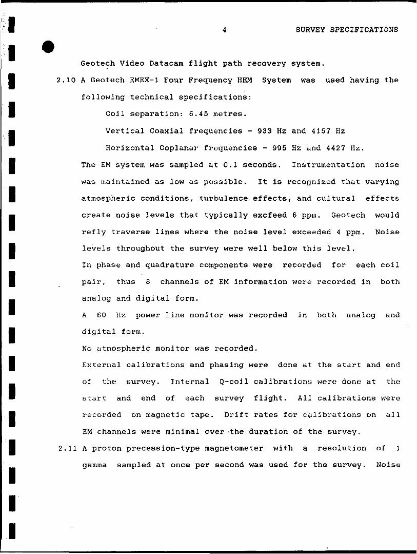
Geotech Video Datacam flight path recovery system.
l 2.10 A Geotech EMEX-1 Four Frequency HEM System was used having the
following technical specifications:
l Coil separation: 6.45 metres.
m Vertical Coaxial frequencies - 933 Hz and 4157 Hz
Horizontal Coplanar frequencies - 995 Hz and 4427 Hz.
l The EM system was sampled at 0.1 seconds. Instrumentation noise
was maintained as low as possible. It is recognized that varying
l atmospheric conditions, turbulence effects, and cultural effects
M create noise levels that typically excfeed 6 ppm. Geotech would
refly traverse lines where the noise level exceeded 4 ppm. Noise
l levels throughout the survey were well below this level.
In phase and quadrature components were recorded for each coil
g pair, thus 8 channels of EM information were recorded in both
analog and digital form.
" A 60 Hz power line monitor was recorded in both analog and
j digital form.
No atmospheric monitor was recorded.
l External calibrations and phasing were done at the start and end
of the survey. Internal Q-coil calibrations were done at the
start and end of each survey flight. All calibrations were
H recorded on magnetic tape. Drift rates for calibrations on all
EM channels were minimal over -the duration of the survey.
l 2.11 A proton precession-type magnetometer with a resolution of l
gamma sampled at once per second was used for the survey. Noise
l
l
l l l l l l l l l l l l l l l l l l i
5 SURVEY SPECIFICATIONS
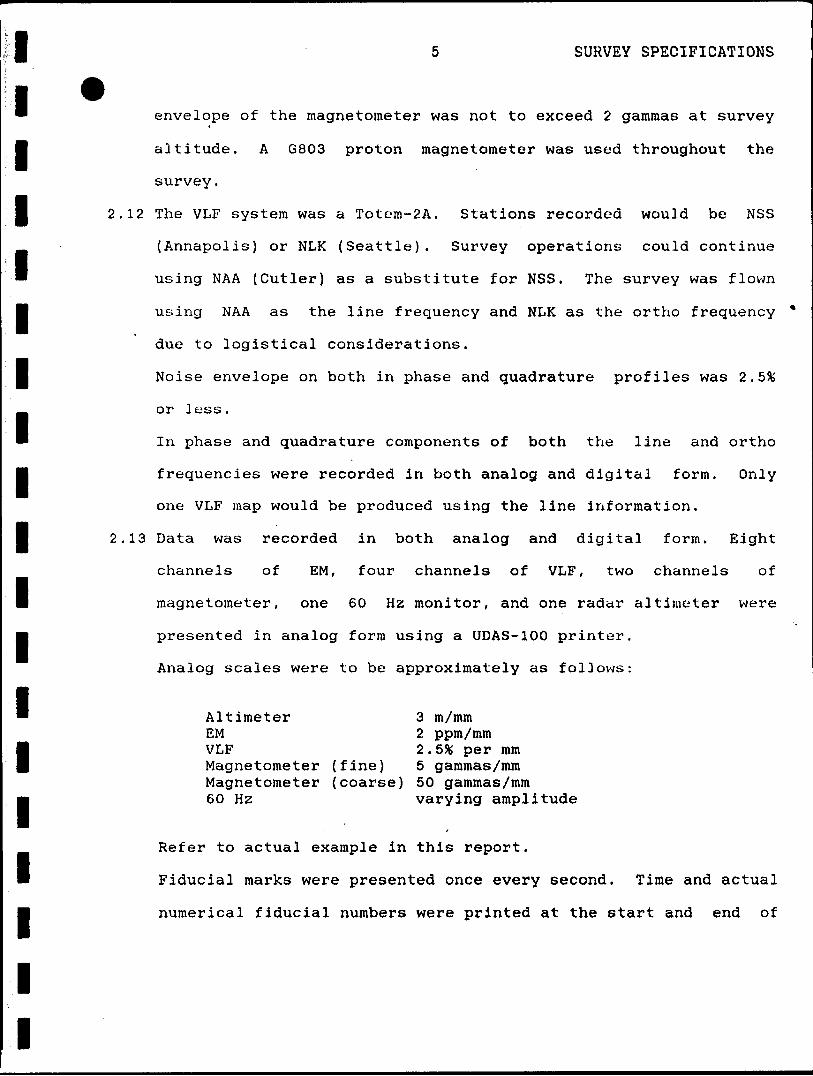
envelope of the magnetometer was not to exceed 2 gammas at survey
altitude. A G803 proton magnetometer was used throughout the
survey.
2.12 The VLF system was a Totem-2A. Stations recorded would be NSS
(Annapolis) or NLK (Seattle). Survey operations could continue
using NAA (Cutler) as a substitute for NSS. The survey was flown
using NAA as the line frequency and NLK as the ortho frequency *
due to logistical considerations.
Noise envelope on both in phase and quadrature profiles was 2 .5%
or less.
In phase and quadrature components of both the line and ortho
frequencies were recorded in both analog and digital form. Only
one VLF map would be produced using the line information.
2.13 Data was recorded in both analog and digital form. Eight
channels of EM, four channels of VLF, two channels of
magnetometer, one 60 Hz monitor, and one radar altimeter were
presented in analog form using a UDAS-100 printer.
Analog scales were to be approximately as follows:
Altimeter 3 m/mmEM 2 ppm/mmVLF 2. 5* per mmMagnetometer (fine) 5 gammas/mmMagnetometer (coarse) 50 gammas/mm60 Hz varying amplitude
Refer to actual example in this report.
Fiducial marks were presented once every second. Time and actual
numerical fiducial numbers were printed at the start and end of
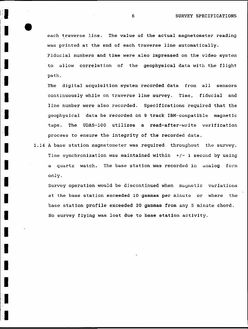
SURVEY SPECIFICATIONSl~ each traverse line. The value of the actual magnetometer reading
l was printed at the end of each traverse line automatically.
Fiducial numbers and time were also impressed on the video system
l to allow correlation of the geophysical data with the flight
path.
" The digital acquisition system recorded data from all sensors
l continuously while on traverse line survey. Time, fiducial and
line number were also recorded. Specifications required that the
l geophysical data be recorded on 9 track IBM-compatible magnetic
tape. The UDAS-100 utilizes a read-after-write verification
process to ensure the integrity of the recorded data.
l 1.14 A base station magnetometer was required throughout the survey.
Time synchronization was maintained within +X- l second by using
l a quartz watch. The base station was recorded in analog form
only.
B Survey operation would be discontinued when magnetic variations
j at the base station exceeded 10 gammas per minute or where the
base station profile exceeded 20 gammas from any 5 minute chord.
I No survey flying was lost due to base station activity.
l
l
l
l
l
l
l l
DATA COMPILATION
l
l l l
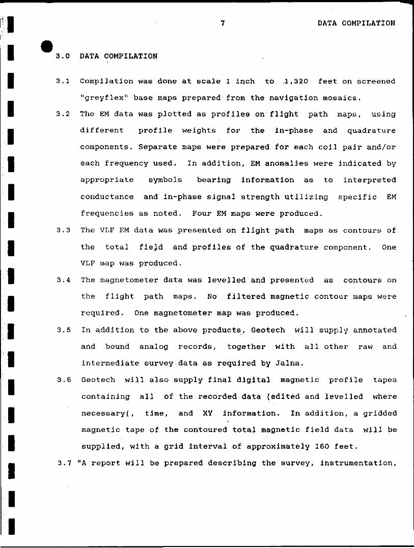
3.0 DATA COMPILATION
l 3.1 Compilation was done at scale l inch to .1,320 feet on screened
"greyflex" base maps prepared from the navigation mosaics.
l 3.2 The EM data was plotted as profiles on flight path maps, using
m different profile weights for the in-phase and quadrature
components. Separate maps were prepared for each coil pair and/or
l each frequency used. In addition, EM anomalies were indicated by
appropriate symbols bearing information as to interpreted
l conductance and in-phase signal strength utilizing specific EM
m frequencies as noted. Four EM maps were produced.
3.3 The VLF EM data was presented on flight path maps as contours of
the total fiejd and profiles of the quadrature component. One
VLF map was produced .
l 3.4 The magnetometer data was levelled and presented as contours on
j the flight path maps. No filtered magnetic contour maps were
required. One magnetometer map was produced.
l 3.5 In addition to the above products, Geotech will supply annotated
and bound analog records, together with all other raw and
l intermediate survey data as required by Jalna.
B 3.6 Geotech will also supply final digital magnetic profile tapes
containing all of the recorded data (edited and levelled where
l necessary(, time, and XY information. In addition, a gridded
magnetic tape of the contoured total magnetic field data will be
l supplied, with a grid interval of approximately 160 feet.
3.7 "A report will be prepared describing the survey, instrumentation,
8 DATA COMPILATION
recorded parameters and scales, digital data format, and any
l other pertinent information. The report will include a listing
of all recognized EM anomalies, noting flight and line number,
l fiducial, in-phase and quadrature component amplitudes for all EM
systems, height above ground, apparent conductance and depth
below ground. Fifteen copies of the report will be required by
U the client. Paterson, Grant and Watson Limited will be preparing
an interpretation report for the survey."
l
l
l
l
l
l
l
l
l
l
l
l
l
l l l l l l l l l l l l l l l l l l l
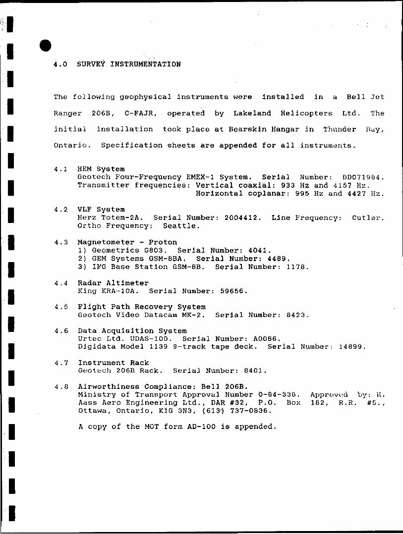
4.0 SURVEY INSTRUMENTATION
The following geophysical instruments were installed in a Bell Jet
Ranger 206B, C-FAJR, operated by Lakeland Helicopters Ltd. The
initial installation took place at Bearskin Hangar in Thunder Buy,
Ontario. Specification sheets are appended for all instruments.
4.1 HEM SystemGeotech Four-Frequency EMEX-1 System. Serial Number: BD071984. Transmitter frequencies: Vertical coaxial: 933 Hz and 4157 Hz.
Horizontal coplanar: 995 Hz and 4427 Hz.
4.2 VLF SystemHerz Totem-2A. Serial Number: 2004412. Line Frequency: Cutler. Ortho Frequency: Seattle.
4.3 Magnetometer - Proton1) Geometrics G803. Serial Number: 4041.2) GEM Systems GSM-8BA. Serial Number: 4489.3) IFG Base Station GSM-8B. Serial Number: 1178.
4.4 Radar AltimeterKing KRA-10A. Serial Number: 59656.
4.5 Flight Path Recovery SystemGeotech Video Datacam MK-2. Serial Number: 8423.
4.6 Data Acquisition SystemUrtec Ltd. UDAS-100. Serial Number: A0086.Digidata Model 1139 9-track tape deck. Serial Number: 14899.
4.7 Instrument RackGeotech 206B Rack. Serial Number: 8401.
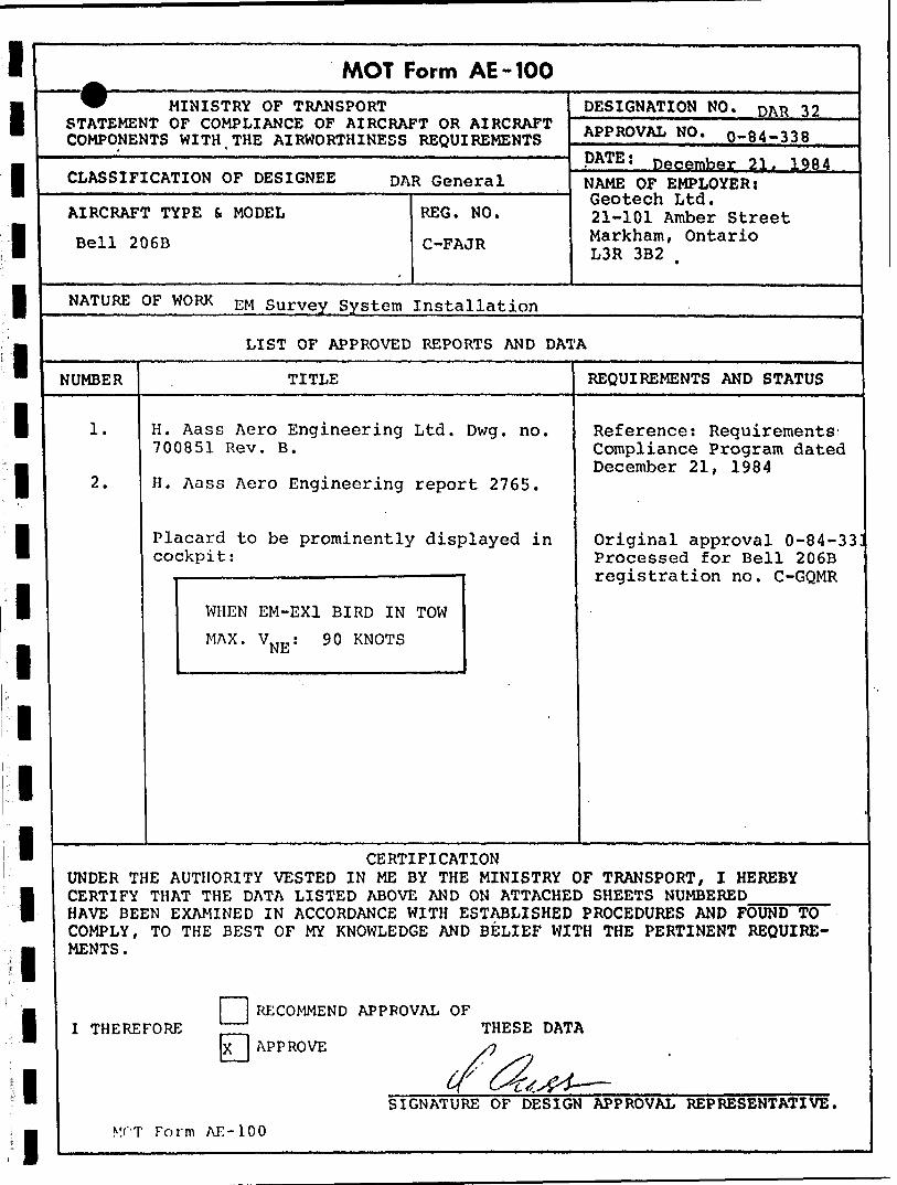
4.8 Airworthiness Compliance: Bell 206B.Ministry of Transport Approval Number 0-84-338. Approved by: H. Aass Aero Engineering Ltd., DAR #32, P.O. Box 182, R.R. #5., Ottawa, Ontario, K1G 3N3, (613') 737-0836.
A copy of the MOT form AD-100 is appended.
l
l l l l l l l l l l l l l l l l l l
10 OPERATIONAL PERSONNEL
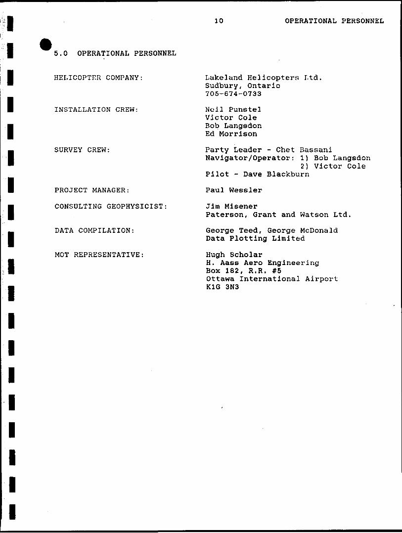
5.0 OPERATIONAL PERSONNEL
HELICOPTER COMPANY:
INSTALLATION CREW:
SURVEY CREW:
PROJECT MANAGER:
CONSULTING GEOPHYSICIST
DATA COMPILATION:
MOT REPRESENTATIVE:
Lakeland Helicopters Ltd. Sudbury, Ontario 705-674-0733
Noil Punstel Victor Cole Bob Langsdon Ed Morrison
Party Leader - Chet Bassani Navigator/Operator: 1) Bob Langsdon
2) Victor Cole Pilot - Dave Blackburn
Paul Wessler
Jim MisenerPaterson, Grant and Watson Ltd.
George Teed, George McDonald Data Plotting Limited
Hugh ScholarH. Aass Aero EngineeringBox 182, R.R. #5Ottawa International AirportK1G 3N3
l l l
11 FIELD LOGISTICS
l
l
l
l
6.0 FIELD LOGISTICS
At the start of the project it was originally Geotech 1 s intent to
J utilize a Bell 206B supplied -from Nipissing Helicopters in North Bay,
B Ontario. MOT approval was obtained for this helicopter, only to find
" that at the last minute Nipissing was forced to supply the designated
l helicopter to another client. Fortunately, Lakeland Helicopters, out
of Thunder Bay, were able to supply a similar 206B. MOT approval was
l obtained and logistics reorganized to accommodate the installation in
Thunder Bay.
B The installation crew consisted of Victor Cole and Bob Langsdon,
B who mobilized from Markham on December 28, 1984, carrying all required
items in the Geotech survey cube van. This cube van was custom
l modified to carry two EMEX birds on its roof. Complete spares and
accessories are carried in the stand-up van box. Noil Punstel joined
l the crew on Decmeber 30th. All crew members arrived in Thunder Bay on
m December 30 and the installation was started tho same day. The
Geotech cube van had arrived at Bearskin Hangar located at Thunder Bay
l airport early in the afternoon.
The installation was completed on January 2, 1985. Delays were
l encountered since our personnel were denied access to the hangar on
j the January 1st holiday. The crew worked outside on this day.
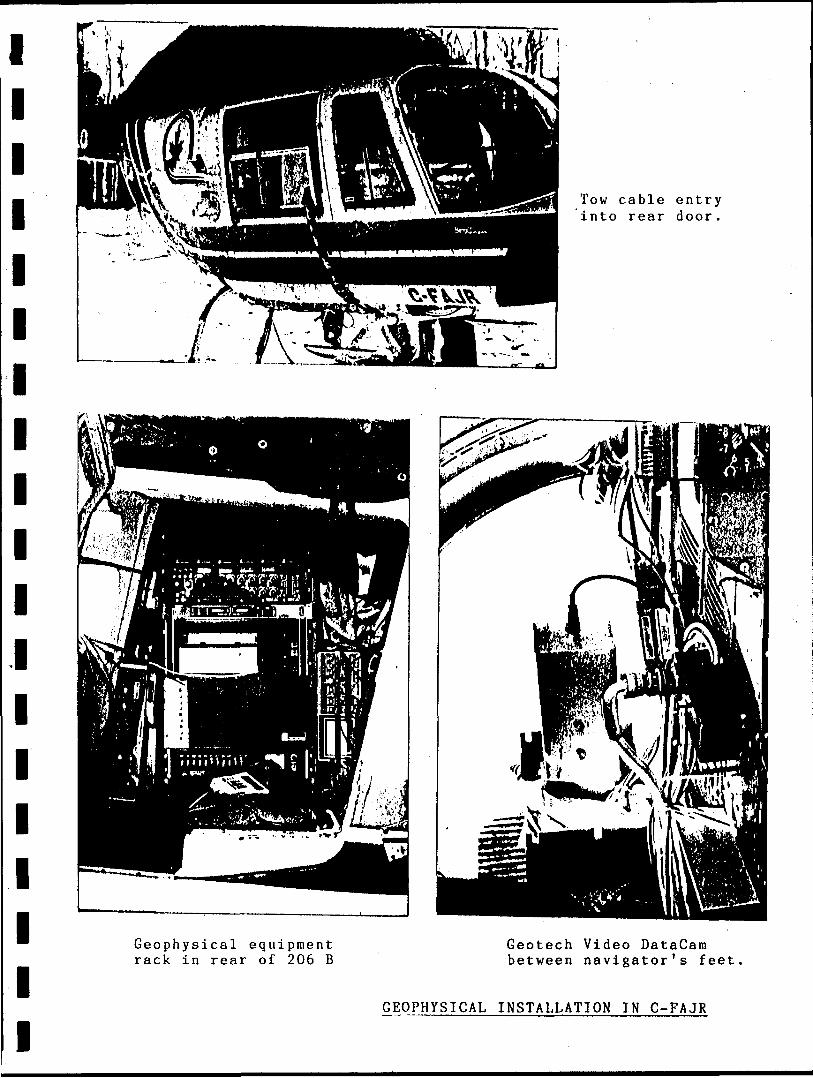
Another helicopter rear door had ta be flown in from Sudbury since the
bubble window on the existing door could not be modified to allow for
tow cable entry. The MOT approval did not allow for modification to
12 FIELD LOGISTICS
the bubble window. Unfortunately the first door shipped in was for
l the wrong side of the helicopter and a second door had to be shipped.
The first test flight was made on January 2, 1985, for
l airworthiness and aerodynamic performance of the system in keeping
M with MOT requirements. It was demonstrated on this flight that the
GEM Systems Inc. GSM-8BA magnetometer did not appear to work within
l specifications with the EMEX-1 system operational specifications. A
second GSM-8 was sent from Toronto but subsequent testing showed
l excessive noise in the airborne environment. The combined
| VLF/magnetometer bird was designed specifically for the GSM-8BA sensor
which is physically very small and lightweight. The aerodynamics of
l this bird appeared ideal under flying conditions but the first pilot
had difficulty with the large EMEX-1 bird. Test flying was further
l hampered by bad weather. While still in Thunder Bay, three days were
lost due to heavy winds and/or snow storms. Fuel logistics for
* remobilization were organized during these weather days.
l Initial attempts to make the magnetometer operational proved
fruitless. No explanation could be readily found since the system
l appeared to work fine in Markham during pre-shipment ground testing.
Software routines developed solely for the use of the GSM-8BA
" magnetometer limited the change-over to a different magnetometer. The
l larger physical size and increased weight (20 Ibs) of the Geometrics
sensor forced an in-field redesign- and construction of a new VLF/mag
l bird. The installation crew spent many hours constructing a new
VLF/mag bird from materials that were locally available in Thunder
l
l
l 13 FIELD LOGISTICS
Bay. The new VLF/mag bird that was produced weighed about 70 Ibs more
l than the original design that used the Gem mag. This was to effect
the overall efficency of the survey by reducing fuel capacity and
l hence helicopter range. Subsequent flying also demonstrated that the
Geometrics mag was susceptible to interference from the HEM system.
This resulted in overall degraded performance of the magnetometer,
l Although the data was within the survey specifications, it is the
opinion of the writer that improved performance could be obtained if
f additional modification were made to the G803 mag preamplifier to
remove the effects of the EM fields. This task is quite difficult and
could not be attempted in the field.
l During this stage, Lakeland Helicopters was unfortunately
required to switch pilots. The new pilot was unable to fly the EMEX-1
l bird and numerous hours were spent teaching him to fly the geophysical
system. During this flying time the radar altimeter failed and had to
be returned to Toronto for warranty repairs. Geotech wat; able to
B provide immediately a replacement radar altimeter with no lost time in
l
l
the field: both Nordair and Air Canada have almost daily flights to
Thunder Bay from Toronto.
The crew was joined by Mr. Ed Morrison, President of Geotech Ltd.
who spent 4 days in Thunder Bay on the calibration of the EM system
and total system debugging. Pilot training took a considerable amount
of time and effort on the part of the field crew. Survey flights were
l attempted using Thunder Bay as a base of operations but again the
radar altimeter failed and had to be returned to Toronto for repairs.
l
l
l 14 FIELD LOGISTICS
l
l
m Time was also spent checking out the second HEM bird which was on site
l for use as a back-up. During this time period a second G803
magnetometer was dispatched from Toronto and was used for parts to get
l the original G803 operational .
On January 16 the helicopter and crew mobilized to Shabaqua,
Ontario whcih was to be the base of operations for the remained of the
l survey. Mr. Morrison and Neil Punstel returned to Markham since the
survey system was now field ready. Mr. Chester Bassani arrived in
l Shabaqua on the 16th to function as overall Party Leader for the
remainder of the flying. Initally time was lost due to severe weather
" that prevented flying. Lakeland once again changed pilots setting the
j project back. Survey flying was attempted with the new pilot but this
proved to be total unacceptable. The HEM bird was almost lost and
l physical damage to the nose cones resulted from the bird being landed
on a fence. This third pilot was replaced with Mr. Dave Blackburn
l whose previous experience proved to be invaluable. Mr. Blackburn was
M to remain with the survey crew throughout the remainder of the job.
Visual navigation in certain parts of the area proved to be
l difficult due do the fact that trees had been removed and new roads
and buildings added. In order to find good navigational features to
m l ine up on at the end of the traverse lines, flight lines were
m extended significantly in the south end of the area. The field crew
was joined by Mr. Jim Misener of Patterson, Grant and Watson and Mr.
l Paul Wessler on January 28 to review survey data. The decision was
made to refly the area in order to improve navigational control and
l 15 FIELD LOGISTICS
improve upon record quality of the magnetometer and HEM data. Three
l major power lines cross the survey area and detract from the HEM
system performance. Mr. Misener returned to Toronto and Mr. Wessler
l remaind to supervise and compile existing survey data.
m Throughout the remaining flying, the project was hampered by the
cold weather and the performance of the data acquistion system. Every
l means possible was used to keep the unit warm enough (-10 C) in order
to ensure that magnetic data was being correctly recorded,
l Unfortunately the Janatrol heater aboard the helicopter failed and
m t ime was again lost. As the helicopter cooled off the data
acquisition system would begin to fail destroying the analog
l information due to incorrect printer operation. The decision was made
to refly the entire survey area in attempts to improve upon the
l navigation with Mr. Chester Bassani as navigator. Mr. Langsdon left
. the field operation and returned to Toronto.
* During the reflying of the survey, the Totem 2A failed and had to
l be returned to Toronto for repairs. A quick turn around was
accomplished and only one day was lost due to this failure. Various
l survey lines were reflown to check the performance of the unit upon
its return to the survey crew.
All survey data was returned to Toronto and presented to Data
U Plotting for final compilation. Analog records were given to
Patterson, Grant and Watson for classification and anomally picking.
l
l
l
l
Numerous new software routines had to be written at Data Plotting to
handle the UDAS format resulting in exceptionally long delivery time.
l l l l l l l l l l l l l l l l l l l
QUALIFICATIONS OP REPORT WRITER
7.0 QUALIFICATIONS OF REPORT WRITER
Paul E. Wessler, CET 8 Jack Court Markham, Ontario L3P 3R3
Current Position:1983-present Vice President and General Manager
Geotech Ltd., 20-101 Amber St., Markham, Ontario
Responsible to the President for the technical administration of a number of research and development projects involving airborne electromagnetic survey instrumentation:- airborne ice thickness measuring system;- development of a 7 frequency HEM system;- development of a Through Ice Bathymetry System for
the Canadian Hydrogrpahic Service.Director of exploration contract services for Geotech. As a field project manager for a number of multi-sensor helicopter-borne contract surveys, directed Geotech activities for a high sensitivity helicopter-borne magnetic gradiometer survey for the Geological Survey of Canada in 1984. Installation of magnetometer and VLF system on small fixed wing aircraft sucty as Cessna 182.
1978 - 1983 Scintrex Ltd.Head of Systems Engineering.
During his tenure at Scintrex Mr. Wessler was responsible for all airborne development projects as well as the execution of airborne contract services performed by Scintrex. A number of geophysical surveys involving HEM systems, magnetometer and radiometric surveys were conducted during his career at Scintrex. Coordinated a 20,000 km multi-channel spectrometer survey for the Geological Survey of Israel; also travelled to Vietnam and East Germany to install and train client's personnel in airborne instrumentation and field procedures. Mr. Wessler has gained exposure to international - geophysical problems. Numerous airborne and vehicular-borne multi-sensor geophysical systems have been designed and implemented under Mr. Wessler's direction on an international level. Among them was the installation of the TRIDEM electromagnetic system for Geosurvey International Limited that is
l l l l l l l l l l l l l l l l l l l
QUALIFICATIONS OF REPORT WRITER
currently flying in Kenya. Mr. Wessler was alsoinvolved with the Scintrex Twin Otter GeophysicalAircraft that went to China in 1979.
1966 - 1978 International Nickel Company - INCO Metals Ltd., Geophysical Research.
Mr. Wessler's initial duties were the field operation and maintenance of the well known INCO Electromagnetic System. The airborne exploration package was installed in an Anson MK-4 aircraft and was to be redesigned and upgraded to a multifrequency EM System installed in a Twin Otter in the early 1970's. During this period, Mr. Wessler was eventually responsible for field airborne operator's direction and training. As a "Design Specialist" within the Geophysical Research Department numerous special projects involving both Airborne and Borehole Geophysical Instrumentaiton were assigned. From 1976 to 1978 Mr. Wessler was "Maintenance Supervisor" responsible for all geophysical and laboratory instrumentation within the geophysical research department. He directed personnel to assist in maintenance and continued throughout his career to execute airborne field services and function as a trouble shooter
thousands of line miles of fixed wing survey were done in the early years.
l l l l l l l l l l l l l l l l l l l
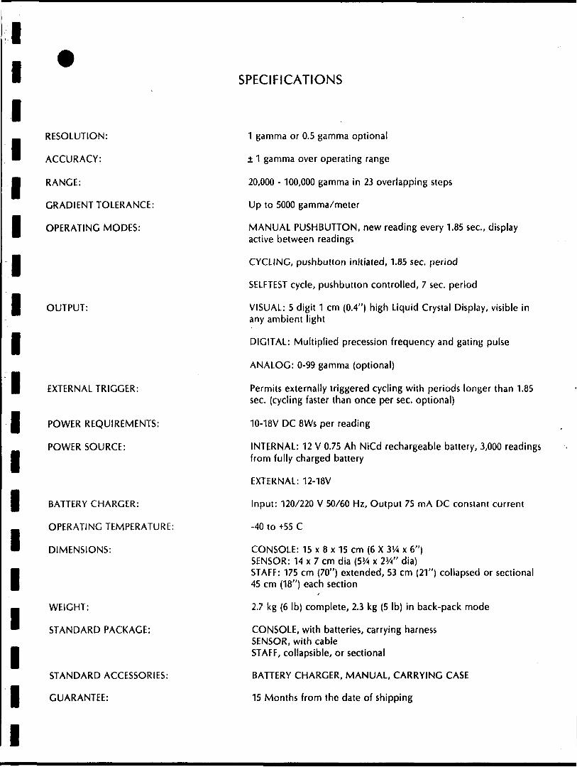
RESOLUTION:
ACCURACY:
RANGE:
GRADIENT TOLERANCE:
OPERATING MODES:
OUTPUT:
EXTERNAL TRIGGER:
POWER REQUIREMENTS:
POWER SOURCE:
BATTERY CHARGER:
OPERATING TEMPERATURE:
DIMENSIONS:
WEIGHT:
STANDARD PACKAGE:
STANDARD ACCESSORIES:
GUARANTEE:
SPECIFICATIONS
1 gamma or 0.5 gamma optional
1 gamma over operating range
20,000 -100,000 gamma in 23 overlapping steps
Up to 5000 gamma/meter
MANUAL PUSHBUTTON, new reading every 1.85 sec., display active between readings
CYCLING, pushbutton initiated, 1.85 sec. period
SELFTEST cycle, pushbutton controlled, 7 sec. period
VISUAL: 5 digit 1 cm (0.4") high Liquid Crystal Display, visible in any ambient light
DIGITAL: Multiplied precession frequency and gating pulse
ANALOG: 0-99 gamma (optional)
Permits externally triggered cycling with periods longer than 1.85 sec. (cycling faster than once per sec. optional)
10-18V DC 8Ws per reading
INTERNAL: 12 V 0.75 Ah NiCd rechargeable battery, 3,000 readings from fully charged battery
EXTERNAL: 12-18V
Input: 120/220 V 50/60 Hz, Output 75 mA DC constant current
-40 to +5S C
CONSOLE: 15 x 8 x 15 cm (6 X 3V4 x 6")SENSOR: 14 x 7 cm dia (5W x 2W d ia)STAFF: 175 cm (70") extended, 53 cm (21") collapsed or sectional45 cm (18") each section
2.7 kg (6 Ib) complete, 2.3 kg (5 Ib) in back-pack mode
CONSOLE, with batteries, carrying harnessSENSOR, with cableSTAFF, collapsible, or sectional
BATTERY CHARGER, MANUAL, CARRYING CASE
15 Months from the date of shipping
l l l l l l l l l l l l l l l l l l l
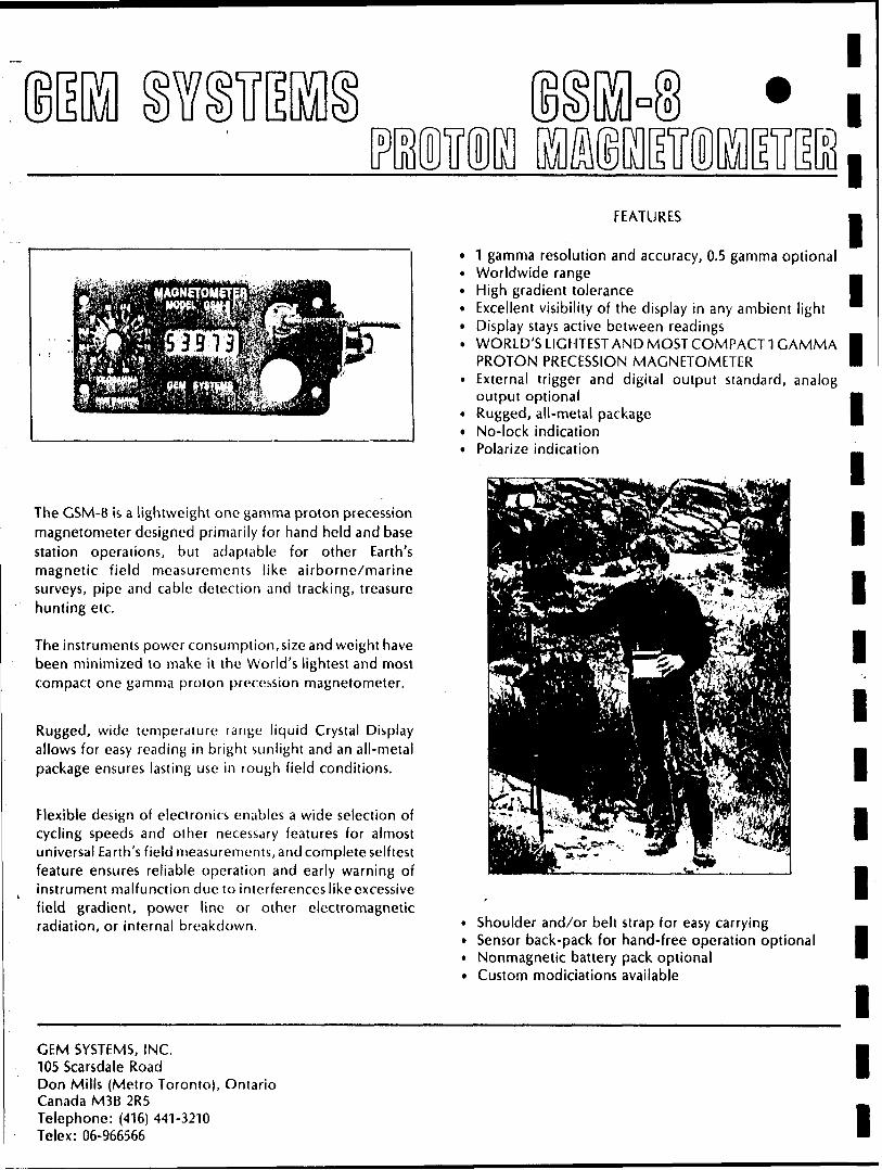
The GSM-8 is a lightweight one gamma proton precession magnetometer designed primarily for hand held and base station operations, but adaptable for other Earth's magnetic field measurements like airborne/marine surveys, pipe and cable detection and tracking, treasure hunting etc.
The instruments power consumption, size and weight have been minimized to make it the World's lightest and most compact one gamma proton precession magnetometer.
Rugged, wide temperature range liquid Crystal Display allows for easy reading in bright sunlight and an all-metal package ensures lasting use in rough field conditions.
Flexible design of electronics enables a wide selection of cycling speeds and other necessary features for almost universal Earth's field measurements, and complete selftest feature ensures reliable operation and early warning of instrument malfunction due to interferences like excessive field gradient, power line or other electromagnetic radiation, or internal breakdown.
FEATURES
1 gamma resolution and accuracy, 0.5 gamma optionalWorldwide rangeHigh gradient toleranceExcellent visibility of the display in any ambient lightDisplay stays active between readingsWORLD'S LIGHTEST AND MOST COMPACT 1 GAMMAPROTON PRECESSION MAGNETOMETERExternal trigger and digital output standard, analogoutput optionalRugged, all-metal packageNo-lock indicationPolarize indication
Shoulder and/or belt strap for easy carrying Sensor back-pack for hand-free operation optional Nonmagnetic battery pack optional Custom modiciations available
GEM SYSTEMS, INC.105 Scarsdale RoadDon Mills (Metro Toronto), OntarioCanada M3B 2R5Telephone: (416) 441-3210Telex: 06-966566
:l ?M'\ ̂ ; BUWr^l
?--^f -^-."^••^'i. j "ubrtvSC7?\T^iC^.
. ...!^ - l "*urai -^i l^-j^
v--NJfto j
^S^S;
ma? iDAWSON ROAD LOTS PROPERTY
AIRBORNE SURVEY BOUNDARY
/V^O
LIMIT OF PROPOSED AIRBORNE SURVEY
i DIRECTION OF FLIGHT LINES Scale: l to 50,000
V/LF 5TAT/OM MSS
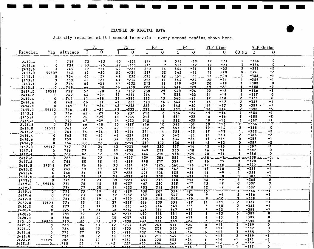
EXAMPLE OF DIGITAL DATA
Actually recorded at 0.1 second intervals - every second reading shown here.
FI. Fiducial
2412.4 - 2412.6 2412.6 2413.0 2413.22413.4 2413.6
.. 2413.8 .2414.0 2414.2 2414.42414.6 2414.8
...2415.0 2415.2 2415.4 2415.62415.3 2416.0 2416.22416.4 2416.6 2416.82417.0 2417.2 2417.42417.6 2417.8 2418.02418.2 2413.42418.62413.3 2419.0 ' 2419.22419.4 2419.6
-. .2419.3 ..-2420.0 2420.2 2420.42420.6 2420.3 2421.0 -. 2421.2 2421.4
- .2421.6 ,.2421. tt 2*22.O 2422.2
Mag
0 0 0
59509 00 0
,. .059511
0 00 0
...-59512 00 00
5951300 0 0
59517 0 Q0 0
595180 0 D0
- 59518 0-- —— o"0 0
59521 0 00 0
595220 0 00
59523Q
Altitude
73S 739 . 745 742 734733 744 749752 749 749748 749 ~
...-746. .. 746 751 752753
"762 761763 759 766767 766 762763 766767765760763771 771 771
—773 777 781776 779 775731733 739.73373627? ...734 737
.730
I
7063 .59 63 66 63 66
-.6457 63 6166 71
..68 . 65 . 70 6766 72
—74.,7274 6275 79 8284 80 7680 81 7171 76 77-75 73 7575
31 *79 33.30 .... 84 SO 77 80 36 33
Q
-23 -25-24 -20 -29 -27 -21 -33-20 -21 --28-21-26 ' -34-21 -29-29-IS -25 -
-25 -27 -824 12 172213 1620 131921 1820-19 20 1921 14 2123 14
-J 5.13 15 25 22 13 19
F2i Q40 -231 42 -23340 -223 50 -234 43 -232 43 -236 41 ' -232 36 -23033 -237 37 -231 35 -23543 -225
"42-232 43 -23245 -237 41 -235 44 -23235 -227 -42 -233 32 -22642 -229 34 -233 35 -25942 -233 41 -230 38 -23346 -227 41 -229 30 -23441 -233 37 -22331 -23139 -223 35 -237 34 -23242 -229 39 -237 45 -22937 -227 33 -230 38 -23442 -233 35 -237 43 . -23042 -233 33 -230 35 -22333 -231 37 -339
.43 .-227-U —— aili ——
F3I
214211220 237 215212 213
238 214 215220
~ 222 ..235212 213210216 237 211212 213 330469 449 444439 448 464442 445 448455 467 453438 437 450466 446 448450 455 467439 434 432443 466 435
Q
714 32 1211 12 1929 7
1314
•. 19 2985 4
10 -2943 4
102230 211 210206 217 225208 208209218 230 213207 203 215230 214 211218 220?31205 201 196211 223
I
543 553554 562
553 549 544540 538 540544 548 551556 551552548 556 553542 534530557 553 •558552 5S4560542 535538548 558549554 547 547551 541 547551 553360551 553551549 553
F4Q-13 -17-21 -13 -23-29 -29 -29-24 -22-26-15-20
1 - 18-24 -22 -35-31
- -30 ~ -33-25 -26 -11-14 -18 -25-24. - -21 -28-24 -23-27-16 -17 -18-21 ——-20 -30-17 -23 -22-12 -19-24-24 -27-16-21 -24-17
VLF LineI
17 1715 18 1720 20 1?22 211718 19
' 1fl19 16 1918 •19 1717 15 1815 16 20
16 1717 16 1416 13 1215 9 9
14 8 78 8787 636L
Q-21 -21-22-20 -20-21 -19 -20-18 -19 -18-17 -17 -14-14 -16 -15-13
-13-13
- -11 -12-13
- -11 -11
" -9 -10-10 -9 -8-9 -9 -9
VLF60 Hz I
133 0 311 12 1 22-- o24 v
2 30 2 120 02 1 13 ~
02 1 T,1 0 4
-8 —— —3 -9 3
-10 3-11-10 -13-13 -13 -12-13-14 -15-13 -14 -16
. 2 2 45 1 23 1 32
-12
-386 -386-388 -390 -383-389 -388 -388-386 -387 -388-388-389 -390
* -386 -388 -387-386 -388 -388-388 -337 -387-387 -387 -386
.---388 . -390 -390-388 -388 -387-385 -387 -387—386 - -386 -388-337 -338 -388-387 -389 -38S-389 -337 -383-389 -391 -389
OrthoQ
0 0
-2 -2 -1-1 0
-2-1 0 0
-1
-5-1 -2 -10 0
-2-2 -1 -2-1 0 0
.-— .-0, --1-3-1 -1 -10 0 0
— -1-1-2-1 -1 -10 i 0 00 0 0-1
-2- D
l
l1
l11
i
1r
il
l l l l l l l l l l l l l l l l l l l
Tow cable entry into rear door .
Geophysical equipment rack in rear of 206 B
Geotech Video DataCam between navigator's feet
GEOPHYSICAL INSTALLATION IN C-FAJR
1
11111 1 1 11
1 1 1 1 1 i i i
MOT Form AE -100—9 —————————— —— ————————————— 1STATEME1 COMPONEl
CLASSIF
MINISTRY OF TRANSPORTMT OF COMPLIANCE OF AIRCRAFT OR AIRCRAFT ITS WITH THE AIRWORTHINESS REQUIREMENTS
ICATION OF DESIGNEE DAR General
AIRCRAFT TYPE 6 MODEL REG. NO.
Bell 206B C-FAJR
DESIGNATION NO. DAR 3 2APPROVAL NO. 0-84-338
DATE: December 21. 1984NAME OF EMPLOYER: Geotech Ltd. 21-101 Amber Street Markham, Ontario L3R 3B2
NATURE OF WORK EM survey System Installation
LIST OF APPROVED REPORTS AND DATA
NUMBER
1.
2.
TITLE
H. Aass Aero Engineering Ltd. Dwg. no. 700851 Rev. B.
H. Aass Aero Engineering report 2765.
Placard to be prominently displayed in cockpit:
WHEN EM-EX1 BIRD IN TOW
MAX. VMC,: 90 KNOTS Nrj
REQUIREMENTS AND STATUS
Reference: Requirements; Compliance Program dated December 21, 1984
Original approval 0-84-33] Processed for Bell 206B registration no. C-GQMR
CERTIFICATION UNDER THE AUTHORITY VESTED IN ME BY THE MINISTRY OF TRANSPORT, I HEREBY CERTIFY THAT THE DATA LISTED ABOVE AND ON ATTACHED SHEETS NUMBEREDHAVE BEEN EXAMINED IN ACCORDANCE WITH ESTABLISHED PROCEDURES AND FOUND TO COMPLY, TO THE BEST OF MY KNOWLEDGE AND BELIEF WITH THE PERTINENT REQUIRE MENTS .
I THERERECOMMEND APPROVAL OF
FORE THESE DATX APPROVE S)
tr't?4*t
A
j — —SIGNATURE OF DESIGN APPROVAL REPRESENTATIVE.
W- T Form AE- 100
111
*DAWSON ROAD LOTS PROPERTY
1i (Dawson Road Lots,
1
(BLOCK - 7)!
,
Thunder Bay Mining Division)
1
1
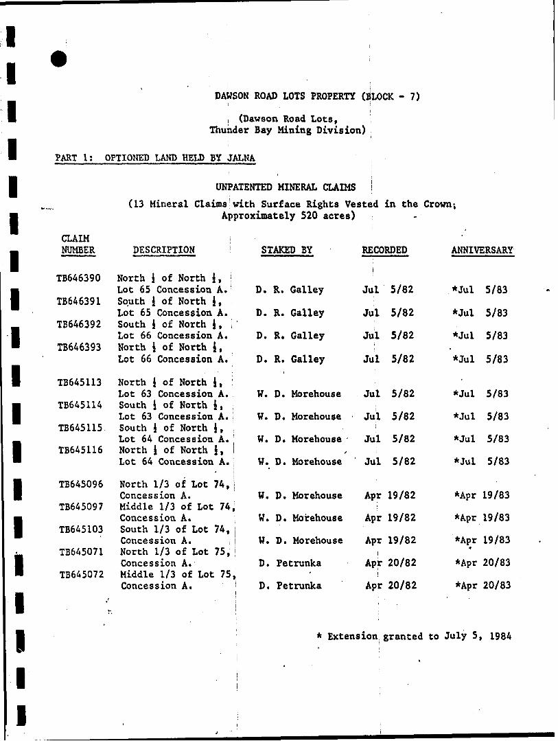
PART l:i
OPTIONED LAND HELD BY JALNA
UNPATENTED MINERAL CLAIMS l
(13 Mineral Claims with Surface Rights Vested in the
1
1
1
1
1
1
1
1
1
iiiii
Crown-,Approximately 520 acres) i
CLAIMNUMBER
TB646390
TB646391
TB646392
TB6463931
TB645113
TB645114
TB645115
TB645116
TB645096
TB645097
TB645103
TB645071
TB645072
DESCRIPTION1
North i of North 4* jLot 65 Concession A.South J of North 4,Lot 65 Concession A.South 4 of North 4*Lot 66 Concession A.North 1 of North J, ;Lot 66 Concession A*
North 4 of North J,Lot 63 Concession A.South i of North 4*Lot 63 Concession A.South J of North J*Lot 64 Concession A.North J of North J,Lot 64 Concession A.
North 1/3 of Lot 74,Concession A.
STAKED BY
D. R. Galley
D. R. Galley1
D. R. Galley
D. R. Galley.
W. D. Morehouse
W. D. Morehouse
W. D. Morehousef
W. D. Morehouse
W. D. Morehouse
i
RECORDED
j
Jul 5/82
Jul 5/82i
Jul 5/82
Jul 5/82
Jul 5/82
Jul 5/82
Jul 5/82i
Jul 5/82
Apr 19/82
,
ANNIVERSARY
*Jul 5/83
*Jul 5/83
*Jul 5/83.*Jul 5/83
'
*Jul 5/83
*Jul 5/83
*Jul 5/83
*Jul 5/83
*Apr 19/83Middle 1/3 of Lot 74,Concession A.South 1/3 of Lot 74,Concession A.North 1/3 of Lot 75,Concession A.
W. D. Morehouse
W. D. Morehouse
D. Petrunka
Apr 19/82
Apr 19/821
Apr 20/82
*Apr 19/83
*Apr 19/83t
*Apr 20/83Middle 1/3 of Lot 75^ ' iConcession A.
•'D. Petrunka
j|
Apr 20/82'
li * Extension granted
1
*Apr 20/83
to July 5, 1984
1111111111111111111
ft1!
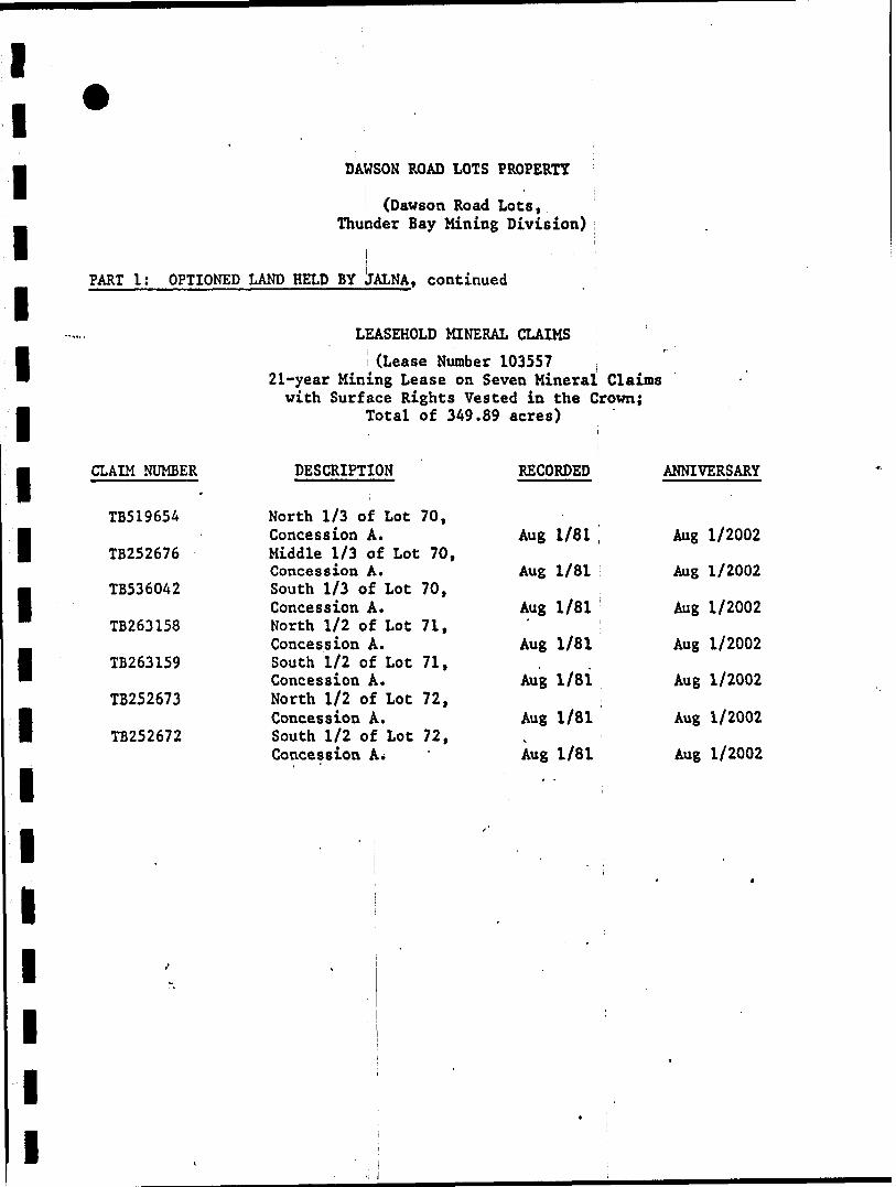
DAWSON ROAD LOTS PROPERTY
(Dawson Road Lots ,Thunder Bay Mining Division) ;s . ' :
PART 1: OPTIONED LAND HELD BY llALNA, continued
LEASEHOLD MINERAL CLAIMS
(Lease Number 103557 : 21-year Mining Lease on Seven Mineral Claimswith Surface Rights Vested in the Crown;
Total of 349.89 acres)
l
CLAIM NUMBER DESCRIPTION RECORDED1
TB519654 North 1/3 of Lot 70,Concession A. Aug 1/81 ,
TB252676 Middle 1/3 of Lot 70,Concession A. Aug 1/81
TB536042 South 1/3 of Lot 70,Concession A. Aug 1/81
TB263158 North 1/2 of Lot 71,Concession A. Aug 1/81
TB263159 South 1/2 of Lot 71, .Concession A. Aug 1/81
TB252673 North 1/2 of Lot 72,Concession A. Aug 1/81
TB252672 South 1/2 of Lot 72,Concession A* Aug 1/81
i . ,i i
|
• p .w
l i |j
( i :
-
ANNIVERSARY
Aug 1/2002
Aug 1/2002
Aug 1/2002
Aug 1/2002
Aug 1/2002
Aug 1/2002
Aug 1/2002
t
t
11i1
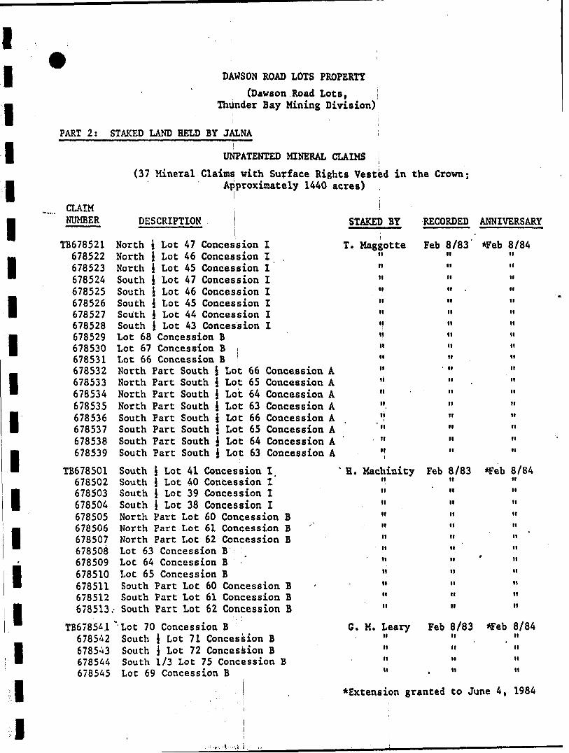
V :DAWSON ROAD LOTS PROPERTY
(Dawson Road Lots,Thunder Bay Mining Division)
iPART 2: STAKED LAND HELD BY JALNA
UNPATENTED MINERAL CLAIMS i
(37 Mineral Claims with Surface Rights Vested in the Crown;
1
1
1
1
1
1
1
1
1
1*
1
1
1
1
1
Approximately 1440 acres) ;
CLAIM iNUMBER DESCRIPTION STAKED BY RECORDED
1
TB678521 North 4 Lot 47 Concession I T. Maggotte Feb678522 North 1 Lot 46 Concession I . "678523 North l Lot 45 Concession I "678524 South i Lot 47 Concession I "678525 South i Lot 46 Concession I "678526 South 4 Lot 45 Concession I "678527 South 4 Lot 44 Concession I "678528 South \ Lot 43 Concession I "678529 Lot 68 Concession B "678530 Lot 67 Concession B j "678531 Lot 66 Concession B "678532 North Part South 4 Lot 66 Concession A . "678533 North Part South 4 Lot 65 Concession A "678534 North Part South J Lot 64 Concession A "678535 North Part South J Lot 63 Concession A "678536 South Part South 4 Lot 66 Concession A "678537 South Part South 4 Lot 65 Concession A "678538 South Part South 4 Lot 64 Concession A "678539 South Part South i Lot 63 Concession A "
TB678501 South 4 Lot 41 Concession I "H. Machinity Feb678502 South i Lot 40 Concession I "678503 South J Lot 39 Concession I "678504 South j Lot 38 Concession I "678505 North Part Lot 60 Concession B "678506 North Part Lot 61 Concession B ' "678507 North Part Lot 62 Concession B "678508 Lot 63 Concession B "678509 Lot 64 Concession B "678510 Lot 65 Concession B "678511 South Part Lot 60 Concession B H678512 South Part Lot 61 Concession B "678513,- South Part Lot 62 Concession B "
TB67854.1 "Lot 70 Concession B G. M. Leary Feb678542 South J Lot 71 Concession B "678543 South j Lot 72 Concession B "678544 South 1/3 Lot 75 Concession B "678545 Lot 69 Concession B "
* Ex t ens ion granted
.8/83ttttHttHiittttHttnMHttttHnH
8/83ttHnittittttHnnnit
8/83Htt11tt
ANNIVERSARY
*Feb 8/84ttHti""nM
II
tl
tl
II
tl
tl
II
tt
II
II
II
*Feb 8/8411nnHnntt
' ttiinttn
*Feb 8/84nM
II
II
to June 4, 1984
.-.'t-.-ii
l l l l l l l l l l l l l l l l l l l
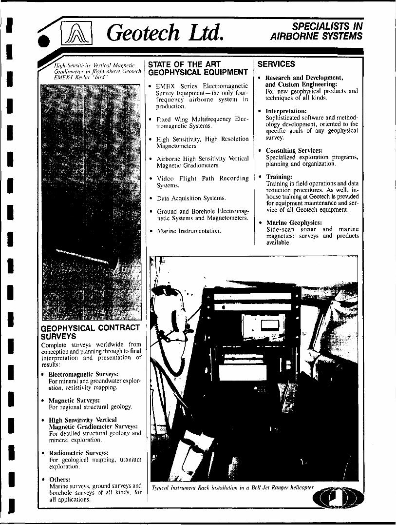
Geotech Ltd.High-Sensitivity Vertical Magnetic Gradiometer in /light above Geotech EMEX-1 Kevlar "bird"
GEOPHYSICAL CONTRACT SURVEYSComplete surveys worldwide from conception and planning through to final interpretation and presentation of results:* Electromagnetic Surveys:
For mineral and groundwater explor ation, resistivity mapping.
* Magnetic Surveys:For regional structural geology.
* High Sensitivity VerticalMagnetic Gradiometer Surveys:For detailed structural geology and mineral exploration.
* Radiometric Surveys:For geological mapping, uranium exploration.
* Others:Marine surveys, ground surveys and borehole surveys of all kinds, for all applications.
STATE OF THE ART GEOPHYSICAL EQUIPMENT
* EMEX Series Electromagnetic Survey Equipment the only four- frequency airborne system in production.
* Fixed Wing Multifrequency Elec tromagnetic Systems.
* High Sensitivity, High Resolution Magnetometers.
* Airborne High Sensitivity Vertical Magnetic Gradiometers.
* Video Flight Path Recording Systems.
* Data Acquisition Systems.
* Ground and Borehole Electromag netic Systems and Magnetometers.
* Marine Instrumentation.
SPECIALISTS IN AIRBORNE SYSTEMS
SERVICES
* Research and Development, and Custom Engineering:For new geophysical products and techniques of all kinds.
* Interpretation:Sophisticated software and method ology development, oriented to the specific goals of any geophysical survey.
* Consulting Services:Specialized exploration programs, planning and organization.
* Training:Training in field operations and data reduction procedures. As well, in- house training at Geotech is provided for equipment maintenance and ser vice of all Geotech equipment.
* Marine Geophysics:Side-scan sonar and marine magnetics: surveys and products available.
Typical Instrument Rack installation in a Bel! Jet Ranger helicopter
APPLICATIONS
Base Metal Mineral ExplorationUsing EMEX Series Airborne EM Systems and Airborne Vertical Magnetic Gradiometer, combined or separately.
Geological MappingUsing Magnetics for structural map ping, Magnetic Gradiometer for detailed structure, Electromagnetic
surveys for resistivity maps and over burden delineation, and Radiometric surveys.Geological mapping can be used to assist in mineral exploration and many engineering applications, such as planning of roadways and pipe lines, geothermal investigations and the search for economic sand and gravel deposits.Groundvvater ExplorationUsing Airborne Electromagnetic techniques.
Uranium ExplorationUsing Multichannel Spectrograj^fc surveys. jff
Marine ExplorationBathymetry using Electromagnetictechniques.Underwater mineral exploration andmapping with Marine Magnetics andSide-scan Sonar.
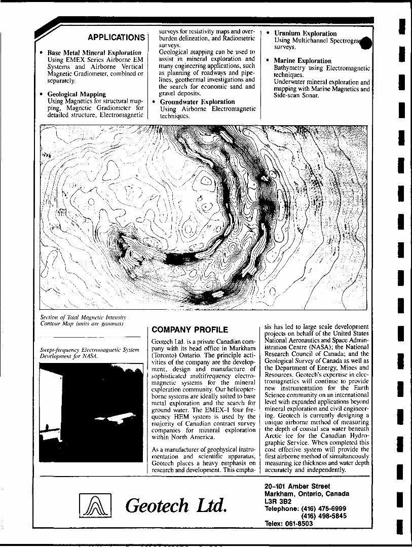
Section of Total Magnetic Intensity Contour Map (units are gammas)
Swept-frequency Electromagnetic System Development for NASA.
COMPANY PROFILEGeotech Ltd. is a private Canadian com pany with its head office in Markham (Toronto) Ontario. The principle acti vities of the company are the develop ment, design and manufacture of sophisticated multifrequency electro magnetic systems for the mineral exploration community. Our helicopter- borne systems are ideally suited to base metal exploration and the search for ground water. The EMEX-1 four fre quency HEM system is used by the majority of Canadian contract survey companies for mineral exploration within North America.
As a manufacturer of geophysical instru mentation and scientific apparatus, Geotech places a heavy emphasis on research and development. This empha
sis has led to large scale development projects on behalf of the United States National Aeronautics and Space Admin istration Centre (NASA); the National Research Council of Canada; and the Geological Survey of Canada as well as the Department of Energy, Mines and Resources. Geotech's expertise in elec tromagnetics will continue to provide new instrumentation for the Earth Science community on an international level with expanded applications beyond mineral exploration and civil engineer ing. Geotech is currently designing a unique airborne method of measuring the depth of coastal sea water beneath Arctic ice for the Canadian Hydro graphic Service. When completed this cost effective system will provide the first airborne method of simultaneously measuring ice thickness and water depth accurately and independently.
Geotech Ltd.20-101 Amber Street Markham, Ontario, Canada L3R 3B2Telephone: (416) 475-6999
(416) 498-5845 Telex: 061-8503
l l l l l l l l l l l l l l l l l l l
EMEX Series Electromagnetic System Applications
Geological Mapping
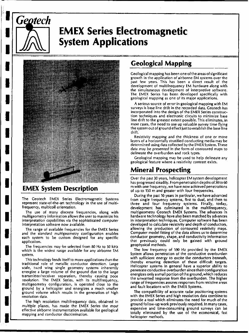
EMEX System Description^^^^The Geotech EMEX Series Electromagnetic Systems represent state-of-the-art technology in the use of multi- frequency, multicoil orientation.
The use of many discrete frequencies, along with multigeometry information allows the user to maximize his interpretation capabilities via the sophisticated computer interpretation software now available.
The range of available frequencies for the EMEX Series and the standard multigeometry configuration enables each system to be custom designed for any specific application.
The frequencies may be selected from 80 Hz to 50 kHz which is the widest range available for any airborne EM system.
This technology lends itself to more applications than the traditional role of metallic conductor detection. Large scale, fixed wing single geometry systems inherently energize a large volume of the ground due to the large transmitter/receiver separation, thereby causing pooi resolution. The EMEX Series, with its multifrequency, multigeometry configuration, is operated close to the ground by a helicopter and energizes a much smaller ground volume which results in the generation of high resolution data.
The high resolution multifrequency data, obtained in multiple planes, has made the EMEX Series the most effective airborne instrumentation available for geological mapping and conductor discrimination.
Geological mapping has been one of the areas of significant growth in the application of airborne EM systems over the past few years. This has been a direct result of the development of multifrequency EM hardware along with the simultaneous development of interpretive software. The EMEX Series has been developed specifically with geological mapping as one of its major applications.
A serious source of error in geological mapping with EM surveys is base line drift in the recorded data. Geotech has incorporated into the design of the EMEX Series construc tion techniques and electronic circuits to minimize base line drift to the greatest extent possible. This eliminates, in most cases, the need to use up valuable survey time flying the system out of ground effect just to establish the base line drift.
Resistivity mapping and the thickness of one or more layers of a horizontally stratified conducting media may be determined using data collected by the EMEX System. These data may be presented in the form of contoured maps to delineate the overburden and rock types.
Geological mapping may be used to help delineate any geological feature where a resistivity contrast exists.
Mineral Prospecting_______Over the past 30 years, helicopter EM system development has progressed steadily. From penetration depths of 30 to 60 m with one frequency, we have now achieved penetrations of up to 150 m and greater with four frequencies.
During the past 10 years in particular, we have advanced from single frequency systems, first to dual, and then to three and four frequency systems. Finally, today, development has culminated in the multifrequency, multigeometry Geotech EMEX Systems. The advances in hardware technology have also been matched by advances in interpretation techniques. Computer software has been developed to calculate resistivity and depth of conductors, allowing the production of contoured resistivity maps. Computer model fitting of the data allows us to determine conductor geometry, shape, and conductivity information that previously could only be gained with ground geophysical methods.
The low frequency of 190 Hz provided by the EMEX System allows penetration of the conductive overburden with sufficient energy to excite the conductors beneath, thereby ensuring detection of these difficult targets. Helicopter systems in general have a superior ability to penetrate conductive overburden since their configuration energizes only a small portion of the ground, which reduces the unwanted response from the overburden. The higher range of frequencies assures responses from resistive areas and fault locations with the EMEX Systems.
The compatibility of accurate radar positioning systems with the EMEX Series and high resolution data combine to provide a tool which eliminates the need for much of the ground follow-up work previously required. In many cases, expensive and time-consuming ground surveys can be totally eliminated by the use of the economical, fast helicopter methods.
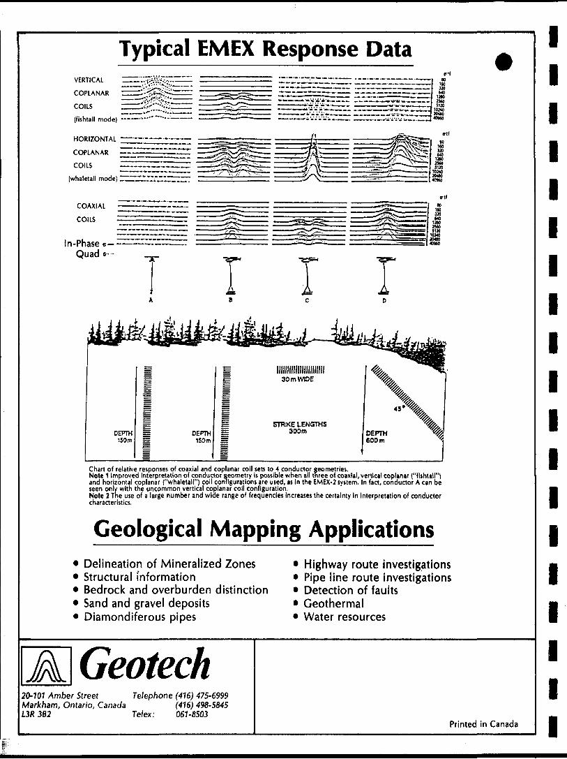
Typical EMEX Response DataVERTICAL
COPLANAR
COILS(fishtail mode) ~-~"-"~
HORIZONTAL
COPLANAR '
COILS
(whaletail mode)
COAXIAL :
COILS
In-Phase s- Quad *- r
Chart of relative responses of coaxial and coplanar coil sets to 4 conductor geometries.Note 1 1mproved interpretation of conductor geometry is possible when all three of coaxial, vertical coplanar ("fishtail")and horizontal coplanar ("whaletail") coil configurations are used, as in the EMEX-2 system. In fact, conductor A can beseen only with the uncommon vertical coplanar coll configuration.Note 2 The use of a large number and wide range of frequencies increases the certainty In interpretation of conductorcharacteristics.
Geological Mapping ApplicationsDelineation of Mineralized Zones Structural information Bedrock and overburden distinction Sand and gravel deposits Diamondiferous pipes
Highway route investigations Pipe line route investigations Detection of faults Geothermal Water resources
A Geotech20-101 Amber Street Telephone (416) 475-6999Markham, Ontario, Canada (416) 498-5845L3R 3B2 Telex: 061-8503
Printed in Canada
l l l l l l l l l l l l l l l l l 1 l
Geotechr^i Geotech EMEX-1 Airborne
Electromagnetic System
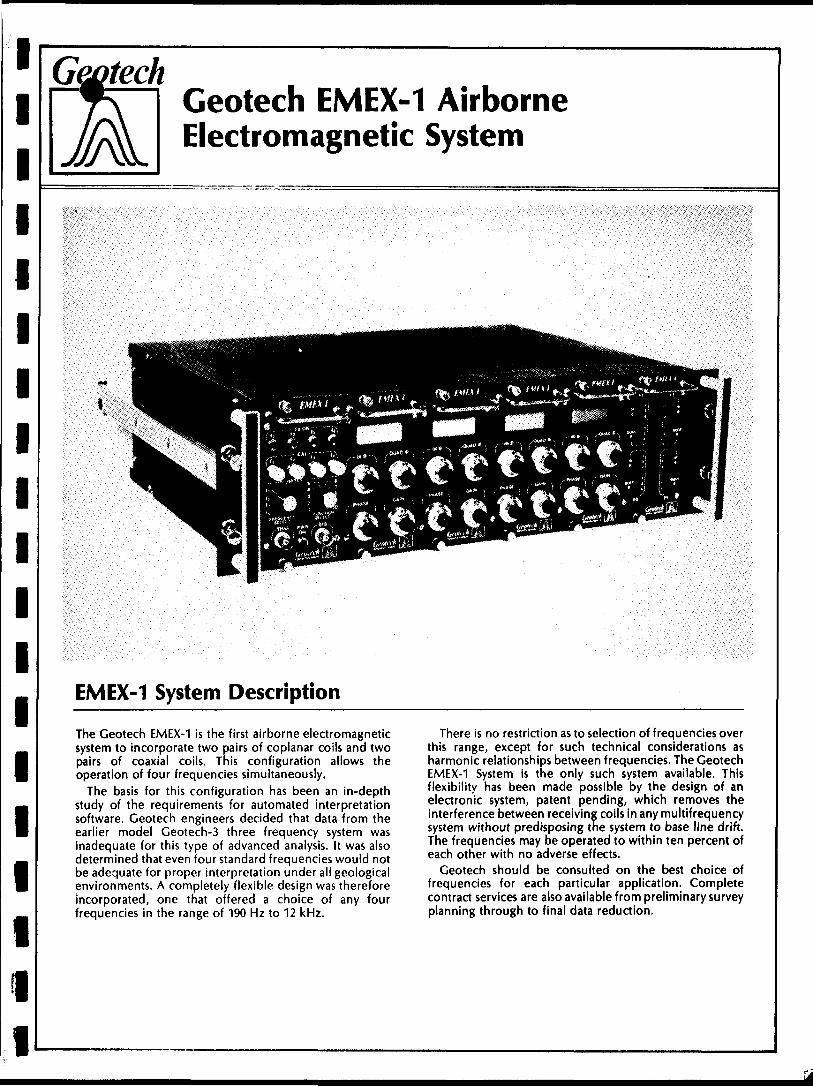
EMEX-1 System Description
The Geotech EMEX-1 is the first airborne electromagnetic system to incorporate two pairs of coplanar coils and two pairs of coaxial coils. This configuration allows the operation of four frequencies simultaneously.
The basis for this configuration has been an in-depth study of the requirements for automated interpretation software. Geotech engineers decided that data from the earlier model Geotech-3 three frequency system was inadequate for this type of advanced analysis. It was also determined that even four standard frequencies would not be adequate for proper interpretation under ali geological environments. A completely flexible design was therefore incorporated, one that offered a choice of any four frequencies in the range of 190 Hz to 12 kHz.
There is no restriction as to selection of frequencies over this range, except for such technical considerations as harmonic relationships between frequencies. The Geotech EMEX-1 System is the only such system available. This flexibility has been made possible by the design of an electronic system, patent pending, which removes the interference between receiving coils in any multifrequency system without predisposing the system to base line drift. The frequencies may be operated to within ten percent of each other with no adverse effects.
Geotech should be consulted on the best choice of frequencies for each particular application. Complete contract services are also available from preliminary survey planning through to final data reduction.
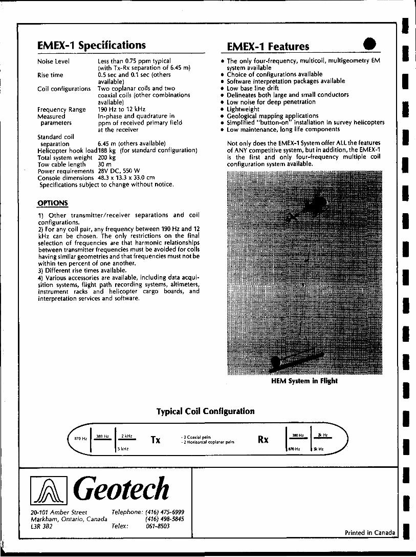
EMEX-1 SpecificationsNoise Level
Rise time
Coil configurations
Less than 0.75 ppm typical(with Tx-Rx separation of 6.45 m)0.5 sec and 0.1 sec (othersavailable)Two coplanar coils and twocoaxial coils (other combinationsavailable)190 Hz to 12 kHzIn-phase and quadrature inppm of received primary fieldat the receiver
Frequency Range Measured parameters
Standard coilseparation 6.45 m (others available)
Helicopter hook Ioad188 kg (for standard configuration) Total system weight 200 kg Tow cable length 30 m Power requirements 28V DC, 550 W Console dimensions 48.3 x 13.3 x 33.0 cmSpecifications subject to change without notice.
OPTIONS
1) Other transmitter/receiver separations and coil configurations.2) For any coil pair, any frequency between 190 Hz and 12 kHz can be chosen. The only restrictions on the final selection of frequencies are that harmonic relationships between transmitter frequencies must be avoided for coils having similar geometries and that frequencies must not be within ten percent of one another.3) Different rise times available.4) Various accessories are available, including data acqui sition systems, flight path recording systems, altimeters, instrument racks and helicopter cargo boards, and interpretation services and software.
EMEX-1 FeaturesThe only four-frequency, multicoil, multigeometry EMsystem availableChoice of configurations availableSoftware interpretation packages availableLow base line driftDelineates both large and small conductorsLow noise for deep penetrationLightweightGeological mapping applicationsSimplified "button-on" installation in survey helicoptersLow maintenance, long life components
Not only does the EMEX-1 System offer ALL the features of ANY competitive system, but in addition, the EMEX-1 is the first and only four-frequency multiple coil configuration system available.
HEM System in Flight
Typical Coil Configuration
380 Hz 2kHz
5kHz
Tx - 2 Coaxial pairs- 2 Horizontal coplanar pairs Rx
A Geotech20-101 Amber Street Telephone: (416) 475-6999Markham, Ontario, Canada (416) 498-5845L3R 3B2 Telex: 061-8503
Printed in Canada
l l l l l l l l l l l l l l l l l l l
Geotech Datacam Video Flight Recorder System
System Description Features
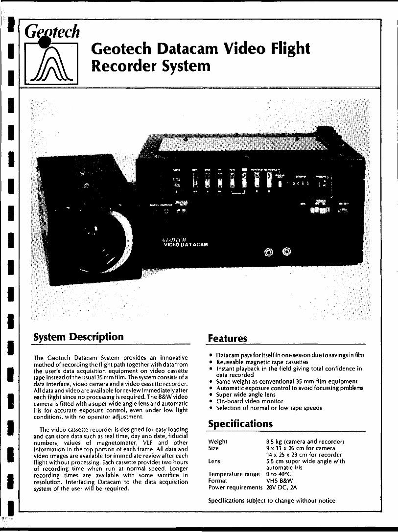
The Geotech Datacam System provides an innovative method of recording the flight path together with data from the user's data acquisition equipment on video cassette tape instead of the usual 35 mm film. The system consists of a data interface, video camera and a video cassette recorder. All data and video are available for review immediately after each flight since no processing is required. The B&W video camera is fitted with a super wide angle lens and automatic iris for accurate exposure control, even under low light conditions, with no operator adjustment.
The video cassette recorder is designed for easy loading and can store data such as real time, day and date, fiducial numbers, values of magnetometer, VLF and other information in the top portion of each frame. All data and video images are available for immediate review after each flight without processing. Each cassette provides two hours of recording time when run at normal speed. Longer recording times are available with some sacrifice in resolution. Interfacing Datacam to the data acquisition system of the user will be required.
Datacam paysfor itself in one season due to savings in filmReuseable magnetic tape cassettesInstant playback in the field giving total confidence indata recordedSame weight as conventional 35 mm film equipmentAutomatic exposure control to avoid focussing problemsSuper wide angle lensOn-board video monitorSelection of normal or low tape speeds
Specifications
Weight Size
Lens
Temperature range Format
8.5 kg (camera and recorder) 9 x 11 x 26 cm for camera 14 x 25 x 29 cm for recorder 5.5 cm super wide angle with automatic iris O to 400 C VMS B&W
Power requirements 28V DC, 2A
Specifications subject to change without notice.
Geotech Datacam Video Flight Path Recovery System
The Geotech Datacam video flight path recovery system complements the Datacam recorder system and is used to locate the flight path points recorded on the video cassette by means of the self-contained B&W CRT monitor. A single control knob selects all playback functions: high speed forward and reverse; slow motion forward and reverse; or single frame. Various forward and reverse speeds are provided to enable the operator to quickly locate the specific frame of interest. A separate push button advances the frames in still mode. Advanced circuitry produces a sharp screen image and eliminates virtually all noise and blur even on slow motion or still frames regardless of tape speed.
Operation of the Datacam recovery system is simplified by the use of an infra-red type remote control unit which duplicates all functions of the control knob. The remote control unit has a range of 6 m extending over an arc of 600 . An optional power unit adapts the recovery unit for operation from any power supply in use throughout the world.
Features* Convenient wide selection of forward and reverse
speeds enables operator to quickly locate frames of interest
* Slow motion and still frames reproduced withour blur or noise
* Instant playback in the field
* All controls duplicated by infra-red remote control unit for ease of operation
* Rugged construction
* Optional power supply for world wide use
Specifications
Weight
Size
Remote control
19kg
56 x 33 x 33 cm
Infra-red, hand held
Specifications subject to change without notice
A Geotech20-101 Amber Street Telephone: (416) 475-6999Markham, Ontario, Canada (416) 498-5845L3R 3B2 Telex: 061-8503
Printed in Canada
i Totem 2AI VLWilectromagnetic
airhnrnp si irvAv instri impnt
Multichannel
l l l l l l l l l l l l l l l l l
airborne survey instrumentSpecifications
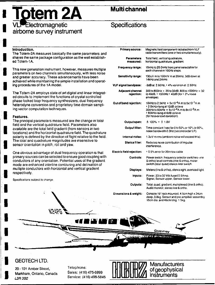
Introduction.The Totem-2A measures basically the same parameters and shares the same package configuration as the well establish ed Totem-1 A.
This new generation instrument, however, measures multiple parameters on two channels simultaneously, with less noise and greater accuracy. These advancements have been achieved while maintaining the simple installation and operat ing procedures of the 1A model.
The Totem-2A employs state of art digital and linear integrat ed circuits to implement the functions of crystal controlled phase locked loop frequency synthesizers, dual frequency heterodyne conversion and proprietary time domain sampl ing vector computation techniques.
Features.The principal parameters measured are the change in total field and the vertical quadrature field. Parameters also available are the total field gradient (from sensors in two locations) and the horizontal quadrature field. The quadrature polarity is defined by the direction of flight relative to the field. The total and quadrature magnitudes are insensitive to sensor orientation in pitch, roll and yaw.
One obvious advantage of dual frequency operation is that primary sources can be selected to ensure good coupling with conductors of any orientation. Potential uses of the gradient mode are enhanced interline contouring and deliniation of multiple conductors with horizontal and vertical gradient respectively.
Specifications subject to change.
Primary source:
Parameter* measured:
Frequency range:
Sensitivity range:
Magnetic field component radiated from VLF radio transmitters (one or two simultaneously).
Total field, vertical quadrature, horizontal quadrature, gradient.
15kHz to 25.0kHz front panel selectable for each channel in 10OHz steps.
130uV m to 10OmV m at 20kHz. 3dB down at 14kHz and 24kHz,
VLF signal bandpass: -3dBat iSOHz,' 4",i variation at i 50Hz.
Adjacent channel rejection:
Out of band rejection:
Output span:
Output filter:
Internal noise:
Sf erics f liter:
Electric field rejection:
Controls:
Displays:
Inputs:
Outputs:
Dimensions 4 weight:
300to800Hz = 20to32dB.800to 1500HZ = 32 lo40dB. * 1500Hz > 40dB(for * 20 o noise envelope).
10kHzto2.5kHz * 5x10-"Amto5x10- 1 Am( 2.5kHz rising at 12dB octave30kHz to 60kHz * 5x10'4Amto8x10-3A m> 60kHz rising at 6dB octave(for no overload condition).
100"X0 = t 1.0V
Time constant 1 sec f or O to 50^o or 10"'o to 90"'o, noise bandwidth 0.3Hz (second order LP).
1.3uV m rms (ambient noise will exceed this).
Reduces noise contribution of impulse interference.
< Q.5% error for 20m tow cable.
Power switch, frequency selector switches i .me b ortho) level controls (line 4 ortho), meter switch (total quad) sferics filter switch.
Meters (line 4 ortho), sferics light, overload light.
Power, 23 to 32 Vdc fused O.SAmp. Signal, Sensor upper, Sensor lower.
Total, quad, gradient, multiplexed (line S ortho). Audio monitor, stereo line i ortho.
Console 19" rack mounted, 4.5cm high x 34cm deep, 3.8kg. Sensor and pre-amplifier assembly 15cm dia. and 46cm lo'ng. 1 5kg.
GEOTECH LTD.
20 -101 Amber Street, Markham, Ontario, Canada L3R3B2
Telephone:Sales: (416)475-6999Service: (416)498-5845
TD Manufacturers of geophysical instruments
GSM-SBPROTON MAGNETOMETER BASE STATION
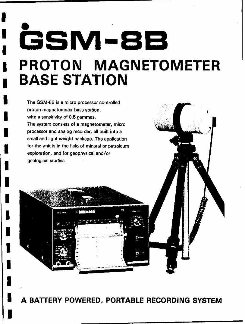
The GSM-8B is a micro processor controlled
proton magnetometer base station, with a sensitivity of 0.5 gammas. The system consists of a magnetometer, micro processor and analog recorder, all built into a
small and light weight package. The application for the unit is in the field of mineral or petroleum
exploration, and for geophysical and/or
geological studies.
A BATTERY POWERED, PORTABLE RECORDING SYSTEM
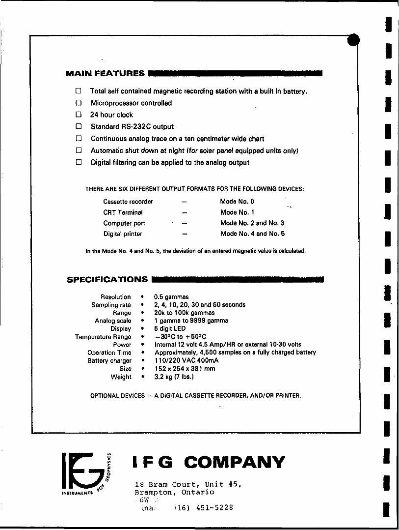
MAIN FEATURES
D Total self contained magnetic recording station with a built in battery.
D Microprocessor controlled
D 24 hour clock
D Standard RS-232C output
D Continuous analog trace on a ten centimeter wide chart
D Automatic shut down at night (for solar panel equipped units only)
D Digital filtering can be applied to the analog output
THERE ARE SIX DIFFERENT OUTPUT FORMATS FOR THE FOLLOWING DEVICES:
Cassette recorder
CRT Terminal
Computer port
Digital printer
Mode No. O
Mode No. 1
Mode No. 2 and No. 3
Mode No. 4 and No. 5
In the Mode No. 4 and No. 5, the deviation of an entered magnetic value is calculated.
SPECIFICATIONS
ResolutionSampling rate
RangeAnalog scale
DisplayTemperature Range
PowerOperation TimeBattery charger
SizeWeight
0.5 gammas2, 4,10, 20, 30 and 60 seconds20k to 100k gammas1 gamma to 9999 gamma6 digit LED-300Cto 4-500 CInternal 12 volt 4.5 Amp/HR or external 10-30 voltsApproximately, 4,500 samples on a fully charged battery110/220 VAC 400mA152x254x381 mm3.2 kg (7 Ibs.)
OPTIONAL DEVICES - A DIGITAL CASSETTE RECORDER, AND/OR PRINTER.
l l l l l l l l l l l l l l l l l l l
IE*INSTHUMENTS
IFG COMPANY18 Brara Court, Unit #5, Brampton, Ontario
1 6W :: ma- 116) 451-5228
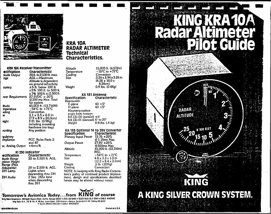
KRA10A Receiver-Transmitter leclfication Characteristicjtude Output 20 ft. to 2,500 ft max.
AGL MaximumAltitude is dependenton ground reflectivity
curacy 5 ft below 100 ft.iS'fc 100 ft. to 500 ft. 79fc 500ft.to2,000ft.
wer Requirements 27.5VDC 20'fc@200 ma Max. Totalfor system
atude 45,000 ft (13,716M) mperature -540C to *71 CC X)fing Convection x 3 .1 x 3.5 x 8.0 in.
(7.9 x 8.9 x 20.3cm) right 2.01 Ibs. (0.9Kg)
including mountinghardware (no tray)Any positionMinting
gulatory )mpliance
ix. Analog Output
FCC Rules Parts 2 and 87 Mmv/ft
teem cationtitude Range scision Height Range (Pilot Adjustable) DH Lamp
DH Audio
Kl 250 indicatorCharacteristic20 to 2,500 ft AGL
20 to 2,500 ft AGL Lights when descending thru DH 2 Sec. IKhz tone when descending thruDH
KINGKRA10AKRA10ARADAR ALTIMETERTechnical Characteristics.
Altitude Temperature Cooling Size
Weight
15,000 ft. (4,572m)M^^^M^Mm
Convection3.26 x 3.94 x 3.26 in.(8.28 x 10.0 x
8.28cm) 0.9 Ibs. (0.4Kg)
tS.--.- 1 -ii. r.
KA 131 Antenna Specification CharacteristicBeamwidth
E-plane 40 5C H-plane 40 5* Mounting surface angle from horizon: KA 131-00 (parallel) 6: KA 131-01 (skewed) 6e to 20' Weight 0.9 Ibs. (.4 kg)
KA 133 optional 14 to 28V converter
HAOARv ALTITUDE
SpecificationPrimary Input Power
Output Power
Altitude
Temperature Size
Characteristic 13.75 20'fc (g 1.15ma Max 27.5V 25% (5500ma Max. 45,000 ft. (13,716m) MSL-540C to -f 71 "C 4.8 x 3.3 x 1.3 in. (12.2 x 8.4 x 3.2cm) .5 Ib. (.23Kg) Convection
Weight CoolingNOTE: In keeping with King Radio Corpora tion's policy of continual product improve ment, design and specifications described herein may be altered without notice.
Tomorrow's Avionics Today.. .from KING of course*ng fix)* Corporilcn. 400 North Rogers Roa9. Outtie. Kansas 6606? * (913) 787-0400 ' TELEX WUD (0) 4-2299 * CABLE: KINGRAO
' - Kng R*).o S.A.. P.O.B No. C. SO Avt Louis Casai. 1716 Cominn Geneva Swicerbnt) * Tel Geneva 96 58 80* TELEX ?8944i KING CH * CABLE KIN3RADIO
m^m^-T IKING' v ;A KING SILVER CROWN SYSTEM.
Ptiflled in U S A
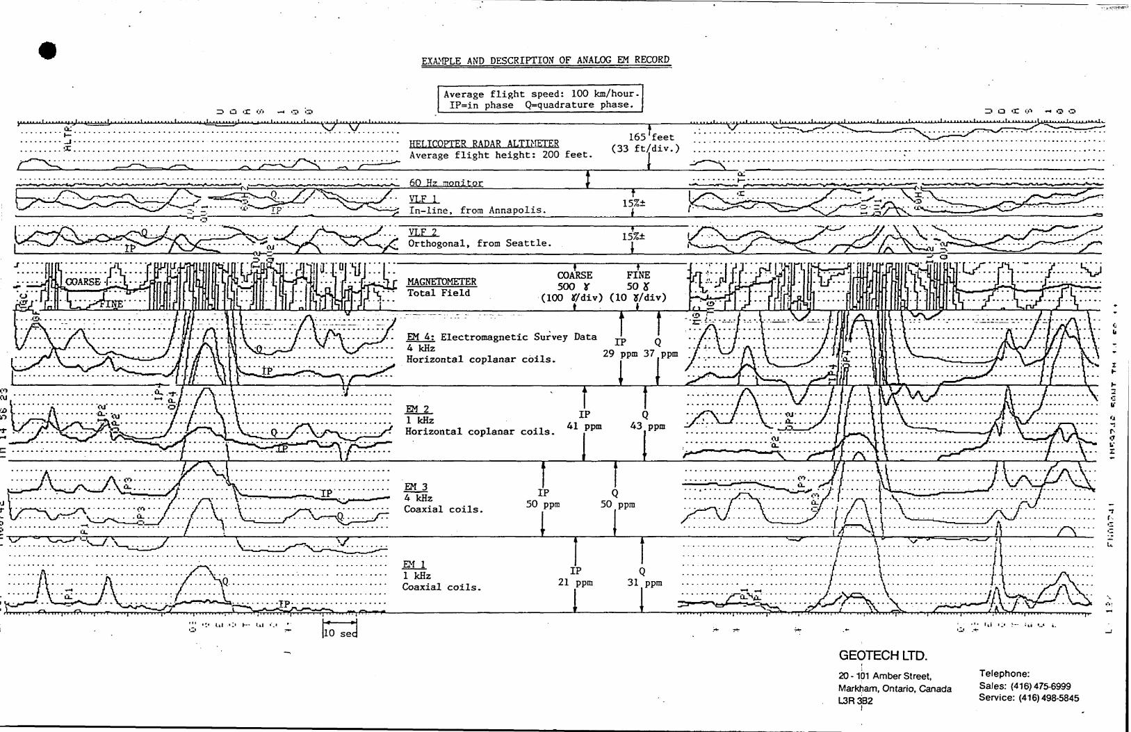
EXAMPLE AND DESCRIPTION OF ANALOG EM RECORD
Average flight speed: 100 km/hour. nVLn phase C^quadrature phase.
jUj •'••••^"••vr" 1j-se. HELICOPTER RADAR ALTIMETER
Average flight height: 200 feet.
165'feet (33 ft/div.)
it 111 'M 111 f f' ' " " ' ' * * '' * M ' M 1 ' " - *-' ' " *' J-U
Z? O 'IT (.rt ~i O O i t..... t^. tl. * i* 11.1 ilit*...... i.i. U^
60 Hz monitorlil
•- VLF l•Z In-line, from Annapolis.
t 15%
. . . . -^v - - \^- - - . . - . - - - - - -- - - -
VLF 2 ^ Orthogonal, from Seattle.
l
MAGNETOMETER Total Field
COARSE FINE500 Y 50 J
(100 JT/div) (10 y/div)-—- —-:-..-; :- .--~-. - - i f
EM A; Electromagnetic Survey Data ,-L l/. 1-TI- -'•* V
29 ppm 37 ppm
j i
4 kHzHorizontal coplanar coils. r i-
b*
O*: r-•7
EM 2l kRzHorizontal coplanar coils.
T IIP
41 ppm 43 ppm -
EM 3 4 kHz Coaxial coils.
IP 50 ppm
Q50 ppm
EM ll kHzCoaxial coils.
IP Q 21 ppm 31 ppm
i t.
GEOTECH LTD.i
20 -101 Amber Street, Markham, Ontario, Canada L3R3B2
Telephone:Sales: (416)475-6999Service: (416)498-5845
l l l l l l l l l l l l l l l l l l l
s.eses HORNEOSO
REPORT ON AIRBORNE MAGNETIC AND
ELECTROMAGNETIC SURVEY
DAWSON ROAD LOTS
THUNDER BAY MINING DIVISION
NORTHWESTERN ONTARIO
for
JALNA RESOURCES LTD.
by
PATERSON, GRANT Se WATSON LIMITED
RECEIVEDJUL O O 1985
MINING LANDS SECTION
Toronto, Canada June 1985
1111111111111111111
TAIV^^^ A. fUJi
l . INTRODUCTION
2. DATA PRESENTATION
2.1 Electromagnetics
2.2 VLF-Electromagnetics
2.3 Magnetics
3 . GEOLOGY
4 . INTERPRETATION
4.1 Magnetic Data
4.2 Electromagnetic Data
5 . RECOMMENDATIONS
Certificate of Qualification
Appendix 1 - Anomaly List
(All maj
Map 784120 Dawson Road Lots:
Map 784121 Dawson Road Lots:
Map 784122 Dawson Road Lots:
Map 784123 Dawson Road Lots:
Map 784124 Dawson Road Lots: -
Map 784125 Dawson Road Lots:
Map 784126 Dawson Road Lots:
52Ai2sweese s.saes HORNE0S0C
l
l
l
5
6
7
8
8
9
11
LIST OF MAPS
(All maps at 1:15,840 scale)
Lots: Total Field Magnetic Contours
Lots: Vertical Co-oxial E.M. Profiles
Road Lots: Horizontal Co-planar E.M. Profiles
Road Lots: Vertical Co-oxial E.M. Profiles
Road Lots: Horizontal Co-planar E.M. Profiles
Road Lots: VLF Total Field Contours with Quadrature
Profiles
CERTIFICATE OF QUALIFICATION
l ^^ I, Donald James Misener, hereby certify:
l 1. that I am a consulting geophysicist and reside at 77 Kingsdale
•j Ave., Willowdale, Ontario M2N 3W3 and practice my profession at
Suite 1214, 111 Richmond St. W., Toronto, Ontario M5H 2G4.
l 2. that I am a registered professional engineer in the province of
Ontario.
l 3. that I am a graduate of the University of Toronto in 1967 with
m the degree of Bachelor of Applied Science; University of
British Columbia in 1971 with the degree of Master of Applied
l Science; and the University of British Columbia in 1973 with
the degree of Doctor of Philosophy.
l 4. that I have been practising my profession continuously since
m graduation.
5. that I personally helped to organize the geophysical work on
l the property described and am familiar with the details of the
work reported. I visited the property to insure the proper
l completion of the field work. I have also studied all available
m maps and reports of the property.
6. that I have no interest, direct or indirect in the properties or
l securities of Jalna Resources Ltd. nor jastHE-^acpecJt to receive
any.
l
ll Donald James Misener, Ph.D., P.Eng.
Toronto, Ontario
June 15, 1985
—
—
l^ INTRODUCTION
l This report describes the results of a combined airborne magnetic and
g electromagnetic survey, totalling 76 line miles, carried out for Jalna
™ Resources Limited over the Dawson Road Lots in northwestern Ontario,
l located approximately 5 km east of Shabagua, Ontario.
The survey area comprised 41 flight lines spaced 1/Sth mile apart, and
directed N 200 E over the entire area.
8 The electromagnetic detector coils mounted in a special frame or "bird"
were towed 100 feet below the helicopter. The average height above
l ground of the bird was 120 feet. The magnetometer-VLF bird was located
^ midway on the HEM tow cable, providing a sensor clearance of
™ approximately 160 feet. The purpose of the survey was to prospect for
l base-metal mineral deposits associated with gold mineralization. The
field work was carried out during January, 1985. Data processing,
interpretation and reporting were done in Toronto during the period
February- June, 1985.
•j This report was prepared for Jalna Resources Ltd. by Paterson, Grant Se
Watson Limited.
l— 2. DATA PRESENTATION
l 2.1 Electromagnetics
The Airborne Electromagnetic Survey Profiles show profiles of
l in-phase and quadrature EM response along all flight lines.
l
l
ll *l These profiles have been transcribed digitally from the analog
data, after removing a constant base level value.
m The Geophysical Interpretation Map is an interpretation map
which shows the inferred axes and strike directions of the
l significant conductors, together with the in-phase anomaly
amplitude in parts per million (ppm) of the primary field
l strength and the apparent conductances derived from the
m vertical half-plane model. The apparent conductance is
determined by applying the in-phase and quadrature anomaly
l amplitudes to the phasor diagram for the vertical half-plane
model, which is shown as an inset on the map. The
l relationship of apparent conductance to the true conductance,
m which in the case of narrow, slab-like bodies is the product
of the electrical conductivity and average thickness, depends
l upon how closely the body approximates the sheet-like form,
and upon how nearly at right angles its strike direction to
l the flight path of the aircraft. Also determined from the
m phasor curves but not shown on the Geophysical Interpretation
Maps are the apparent depths to the tops of the conductors,
l Although the phasor curves are often able to distinguish
between conditions of comparatively thick and thin overburden,
l
l
l
the depth estimates which they give are not generally
reliable. Some of the more common reasons for this are:
l l
(i) the conductivity of the body changes with the depth;
l (ii) the conductor plunges;
m ( iii) the dip is substantially less than vertical;
(iv) interference from conductive overburden or host-rock
l has distorted the anomalies; or
(v) the body has too short a strike length to give a good
l half-plane response
Any of the conditions enumerated above may affect the anomaly
l amplitudes. Some will cause roughly proportionate changes in
both phases, so that the depth estimates tend to be more
l seriously affected than the conductance estimates.
The conductance values are divided into groups and the symbols
l given in the Geophysical Interpretation Map indicate the range
into which each analysis falls. This procedure generally tends
l to make the work of diagnosis easier. Thus, most overburdens
m have apparent conductances which fall into the lowest range on
the scale (l 2 mhos), whereas conductive clay deposits may have
l apparent conductances in the next higher range (2-5 mhos).
Also included as a general rule in the two lowest ranges are
l
l
l
l
the very weak bedrock conductors, such as unmineralized faults
and shears.
ll
Ordinarily, the flat-lying surficial deposits are easily
l distinguished from these bedrock and structural features by the
—m shapes of their responses, and wherever this has been possible
they are identified on the map with the symbol S. The higher
l ranges in the scale of apparent conductances ( ^ 5 mhos )
indicate that a significant fraction of the electrical
l conduction is electronic rather than electrolytic in nature.
j Materials which conduct electronically are limited to the
™ metallic sulphides and to graphite. Thus, the higher apparent
l conductance categories are generally limited to graphite- and
to sulphide-bearing rocks.
lj The apparent conductance of a rock unit, in mhos, is very
B largely an indicator of its electrical properties. The value
l is affected to some extent by the strike length of the body (if
it is short), and by the dip; but these effects are
l comparatively minor, and are unlikely to cause more than a 301
— change. A strong conductance ( ^ 20 mhos) indicates
well-connected mineralization extending throughout a fairly
l large region, and this usually suggests either graphitic zones
or massive sulphides. Such features generally respond well to
f ground surveys using closely-coupled systems such as the
— horizontal loop method. Poor to moderate conductances (4 to 20
™ mhos) may originate from massive sulphides, if they are not
l
l
l
ll
well connected, or if they are of a poorly-conducting variety
l such as some forms of pyrite and galena. Greater care and more
m thoughtful planning are often needed to detect these bodies in
follow-up surveys on the ground.
lAppendix l provides a tabulation of anomaly amplitude (in ppm),
l apparent conductances (in mhos), and apparent depths of burial,
m for all significant EM conductors in the area. These
interpretations are also presented in the Geophysical
l Interpretation Map on a topographic base to permit direct
correlation with the available geology, and to assist in the
l ground follow-up program.
2.2 VLF Electromagnetics
l The Hertz Totem 2A airborne VLF electromagnetic system was used
on the present survey. Two stations, Annapolis, Maryland (NSS)
l and Seattle, Washington (NLK) were recorded, using Cutler,
H Maine (NAA) as a substitute for NSS. The in-phase (total
field) and quadrature components for both the "line" and
l "ortho" frequencies were recorded in both analog and digital
form. The "line" information, either Annapolis or Cutler, were
l produced as contours of the total field and profiles of the
M quadrature response.
l
l
l
l
ll
Due to the high frequency { ~15 kHz) of the VLF electromagnetic
l signal, the method is capable of detecting bodies of small
•j dimensions and sources which may be described as partially
disseminated (i.e. not massive sulphide conductors). In
l addition, fault and/or shear zones, and alteration zones (or
halos) exhibit a strong response using the VLF method.
m The major disadvantage of the VLF method is also a direct
result of operating in the "high" frequency or radio range.
l Shallow zones of poor to moderate conductivity will exhibit
strong VLF responses. These spurious features often correlate
with changes in the depth of conductive overburden or with
conductive topographic features.
l 2.3 Magnetics
The Total Field Magnetic Map shows contours of the total
l magnetic field, uncorrected for regional variation. Whether
m an EM anomaly with a magnetic correlation is more likely to be
caused by a sulphide deposit than one without depends on the
l type of mineralization. An apparent coincidence between an EM
and a magnetic anomaly may be caused by a conductor which is
l also magnetic, or by a conductor which lies in close proximity
m to a magnetic body. The majority of conductors which are also
magnetic are sulphides containing pyrrhotite and/or magnetite.
l
l
l
- 7 -l l
Conductive and magnetic bodies in close association can be -
l and often are - graphite and magnetite. It is often very
m difficult to distinguish between these cases. If the conductor
is also magnetic, it will usually produce an EM anomaly whose
l general pattern resembles that of the magnetics. If the
conductor is strongly magnetic, the amplitude of the in-phase
l
l
l
l
l
l
EM anomaly will be weakened; and if the conductivity is also
weak, the in-phase EM anomaly may even be reversed in sign.
3. GEOLOGY
The region is underlain by a complex of Archean undifferentiated
metavolcanics and metasediments. Along the northern boundary of
the Dawson Road Lots survey area the present geological mappingm
indicates a change to a predominately metasedimentary suite of
l arkose, conglomerate and greywacke.
l
l
Immediately northeast of the present study area, diabase dikes
and/or sills have been mapped and extensive northwest-southeast
striking iron formations have been mapped south of the area. The
l present aeromagnetic map indicates that similar feature (i.e.
diabase, iron formation) may be present, south of the highway
within the survey area.
l l lflj To date, two gold occurrences have been discovered at the western
end of the survey area, south of the highway, and are located
l the within metavolcanic-metasedimentary sequence. Copper-zinc
•j mineralization has been noted to the north of survey area and is
associated with the regional diabase sill/dike complex.
l4 . INTERPRETATION
lm 4 .1 Magnetic Data
The total magnetic field contour map over the Dawson Road Lots
l is dominated by two magnetic patterns; a disrupted, linear 200
nanotesla (nT) anomaly striking ESE-WNW across the map, north
l of the highway and a complex of strike limited, 400 to 600
M nT, anomalies south of the highway.
l The northern pattern correlates with the buried boundary of
the metavolcanics. Along the northern edge of the survey area,
l the magnetic pattern becomes more subdued, reflecting the
M underlying weakly magnetic metasediments. The area south of
™ the highway is dominated by a severely disrupted positive
l magnetic feature that correlates with either an intrusive
gabbro or iron-rich metavolcanics. North of the transmission
l line the gabbroic signature is replaced by a more
— linear -to-lenticular anomaly pattern that correlates with
™ the metavolcanic-metasedimentary suite.
l
ll
The disruption of the magnetic patterns, as noted previously,
l is evidence of two major fault/shear trends in the area. An
j ESE-WNW trend strikes subparallel to the lithology and has been
— interpreted from the eastern edge of the area extending west to
l Line 13. The second more evident trend varies in direction
from N-S to NE-SW and disrupts both the lithology and the
l earlier ESE-WNW trend.
4.2 Electromagnetic Data
l The electromagnetic (HEM) conductors detected on the Dawson
Road Lots may be separated into two possible classes. The
l first class exhibits good line-to-line correlation and extends
— across many flight lines. In general, this class of conductors
parallels, or is coincident with, a good VLF conductor and
l correlates with a lithologic unit within the metavolcanic-
metasedimentary suite (e.g. Target A). The second class of
g conductors possesses a more limited strike extent (four flight
— lines or less), may or may not correlate with a VLF conductor,
™ and dos not correlate with regional formational trends (e.g.
l
—
l
l
l
Target B).
Two major class one, or formational conductive zones have been
detected on the Dawson Road Lots. The first zone (Target A)
- 10 -l l
lies immediately south of the highway, extending from Line 15
g to Line 26. The second zone strikes WNW-ESE along the southern
— edge of the survey area and crosses into the Jalna Resources
" property between Lines 9 and 17. Two zones of class two or
U discrete, non-formational, conductors have been detected south
of the transmission line. The first suite of discrete
l anomalies lies south of the Jalna property, between Lines 6 and
— 10, the second zone lies within the claim block, crossing Lines
B 15 and 16 (Target B).
l Three target areas have been selected for further work and will
be discussed below in detail:
lTarget A; Located on the northern edge of the metavolcanic
" suite, immediately south of the highway. As noted previously,
—j the conductor probably correlates with a single metavolcanic
unit. The strongest portion of the conductor lies between
l Lines 21 and 23, near the junction of major WNW-ESE and NNE-SSW
faults. Calculated depths indicate overburden and metasediment
lcover of 250 feet or greater in the area of highest
conductance.
l Target B; This discrete, two line conductor (Lines 15 and 16)
is located along the southern edge of strongly magnetic
m gabbroic intrusive. The zone exhibits relatively weak
l
l
l
l l
conductivity and an increasing depth of burial from west to
" east. The zone is terminated on the western end by a major
M NNE-SSW shear zone.
l Target C; The portion of the southern formational conductor
that crosses into the Jalna Resources claim block has been
™ denoted as Target C. On Lines 10 and 11, the conductive zone
m possesses poor to moderate conductivity (2 to 5 mhos) and a
depth of burial of approximately 100 feet. Both the magnetic
l and VLF interpretations indicate disruption of the conductive
zone by NNE-SSW shearing.
M 5. RECOMMENDATIONS
As a result of the geophysical interpretation of the HEM, VLF-EM
l and aeromagnetics on the Dawson Road Lots the following tasks
should be undertaken as part of a continuing exploration strategy
m for sulphide-related gold mineralization.
Task l:
l Processing of the total field aeromagnetics to produce colour and
contour plots of the first vertical derivative and apparent
m magnetic susceptibility. These maps will prove invaluable for
•j interpreting the underlying volcanic sedimentary sequences, for
delineating fault structures and for isolating granite/gabbroic
l
l
l
lll l
- 12 -
l
l
intrusives. The correlation of the detailed interpretation of the
processed magnetics with the HEM and VLF-EM will provide a stronger
link between ore deposition and possible structural/lithological
l controls.
Task 2;
Targets A, B and C should be followed-up on the ground using the
following techniques:
l i) Detailed geological mapping and geochemical sampling.
l ii) Ground VLF and magnetics on a 100 metre grid, with a
m station spacing of 25 m.
l iii) Induced polarization surveys of all three targets on the
same grid as the VLF-magnetics.
l
l
l
l
l
l
l
l
l l l l l l l l l l l l l l l l l l l
- 13 -
Respectfully submitted,
PATERSON, GRANT fc WATSON LIMITED
D. J. Misener,
Consulting Geophy^
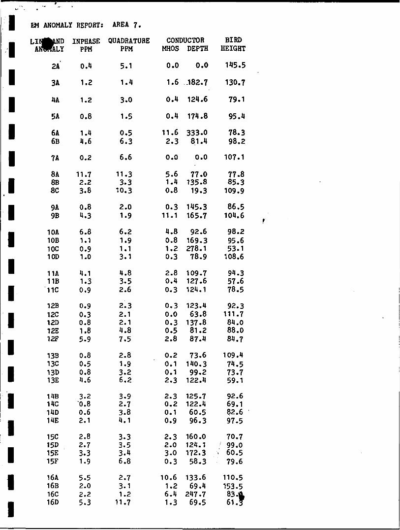
l EM ANOMALY REPORT: AREA ?.
m LIN^LND l ANHALY
1
1
1
1
1
1
1
1
1
1
1
1
1
1
1
1
1
2A
3A
MA
5A
6A6B
7A
8A8B 8C
9A 9B
10A10B10C10D
11A11B11C
12B12C12D12E12F
13B13C13D13E
14B 14C14D14E
15C15D15E15F
16A 16B16C 16D
INPHASE PPM
0.41.2
1.2
0.8
1.44.6
0.2
11.72.23.8
0.8 1.3
6.81.10.91.0
4.11.30.9
0.90.30.81.85.9
0.80.50.84.6
3.2 0.80.62.1
2.82.73.31.9
5.5 2.02.2 5.3
QUADRATURE CONDUCTOR PPM MHOS DEPTH
5.1
1.4
3.0
1.5
0.56.3
6.6
11.33.3
10.3
2.0 1.9
6.21.91.13.1
H. 83.52.6
2.32.12.14.87.5
2.81.93.26.2
3.9 2.73.84.1
3.33.53.46.8
2.7 3.11.2
11.7
0.0
1.6
0.4
0.4
11.62.3
0.0
5.61.4 0.8
0.3 11.1
4.80.81.20.3
2.80.40.3
0.30.00.30.52.8
0.20.10.12.3
2.3 0.20.10.9
2.32.03.00.3
10.6 1.26.4 1.3
0.0
.182.7
124.6
174.8
333.081.4
0.0
77.0135.8 19.3
145.3 165.7
92.6169.3278.178.9
109.7127.6124.1
123.463.8
137.881.287.4
73.6140.399.2
122.4
125.7 122.460.596.3
160.0124.1172.358.3
133.6 69.4
247.7 69.5
BIRD HEIGHT
145.5
130.7
79.1
95.4
78.398.2
107.1
77.885.3
109.9
86.5 104.6
98.295.653.1
108.6
94.357.678.5
92.3111.784.088.084.7
109.474.573.759.1
92.6 69.182.697.5
70.799.0
f 60.579.6
110.5 153.583 4 61 .f
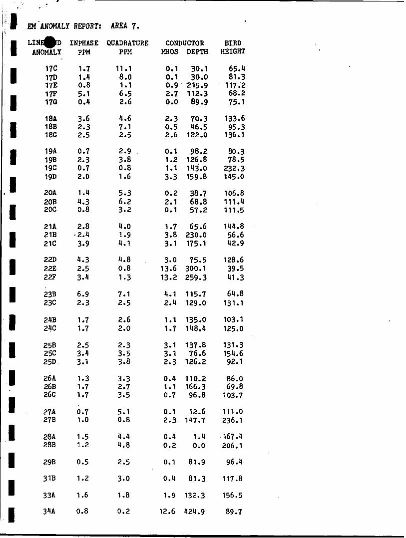
1111111111111111111
EM 'ANOMALY REPORT:
LINE^D INPHASE ANOMALY PPM
17C17D17E17F17G
18A18B 18C
19A 19B19C19D
20A20B20C
21A21B 21C
22D22E22F
23B23C
24B 24C
25B 25C25D
26A26B26C
27A27B
28A28B
29B
31B
33A
34A
1.71.40.85.10.4
3.62.3 2.5
0.7 2.30.72.0
1.44.30.8
2.8•2.4 3.9
4.32.53.4
6.92.3
1.7 1.7
2.5 3.43.1
1.31.71.7
0.71.0
1.51.2
0.5
1.2
1.6
0.8
AREA 7.
QUADRATURE PPM
11.18.01.16.52.6
4.67.1 2.5
2.9 3.80.81.6
5.36.23.2
4.01.9 4.1
4.80.81.3
7.12.5
2.6 2.0
2.3 3.53.8
3.32.73.5
5.10.8
4.44.8
2.5
3.0
1.8
0.2
CONDUCTOR MHOS DEPTH
0.10.10.92.70.0
2.30.5 2.6
0.1 1.21.13.3
0.22.10.1
1.73.8 3.1
3.013.613.2
4.12.4
1.1 1.7
3.1 3.12.3
0.41.10.7
0.12.3
0.40.2
0.1
0.4
1.9
12.6
30.130.0
215.9112.389.9
70.346.5 122.0
98.2 126.8143.0159.8
38.768.857.2
65.6230.0 175.1
75.5300.1259.3
115.7129.0
135.0 148.4
137.8 76.6126.2
110.2166.396.8
12.6147.7
1.40.0
81.9
81.3
132.3
424.9
i
BIRD HEIGHT
65.481.3117.268.275.1
133.695.3 136.1
80.3 78.5
232.3145.0
106.8111.4111.5
144.856.6 42.9
128.639.541.3
64.8131.1
103.1 125.0
131.3 154.692.1
86.069.8103.7
111.0236.1
167.4206.1
96.4
117.8
156.5
89.7
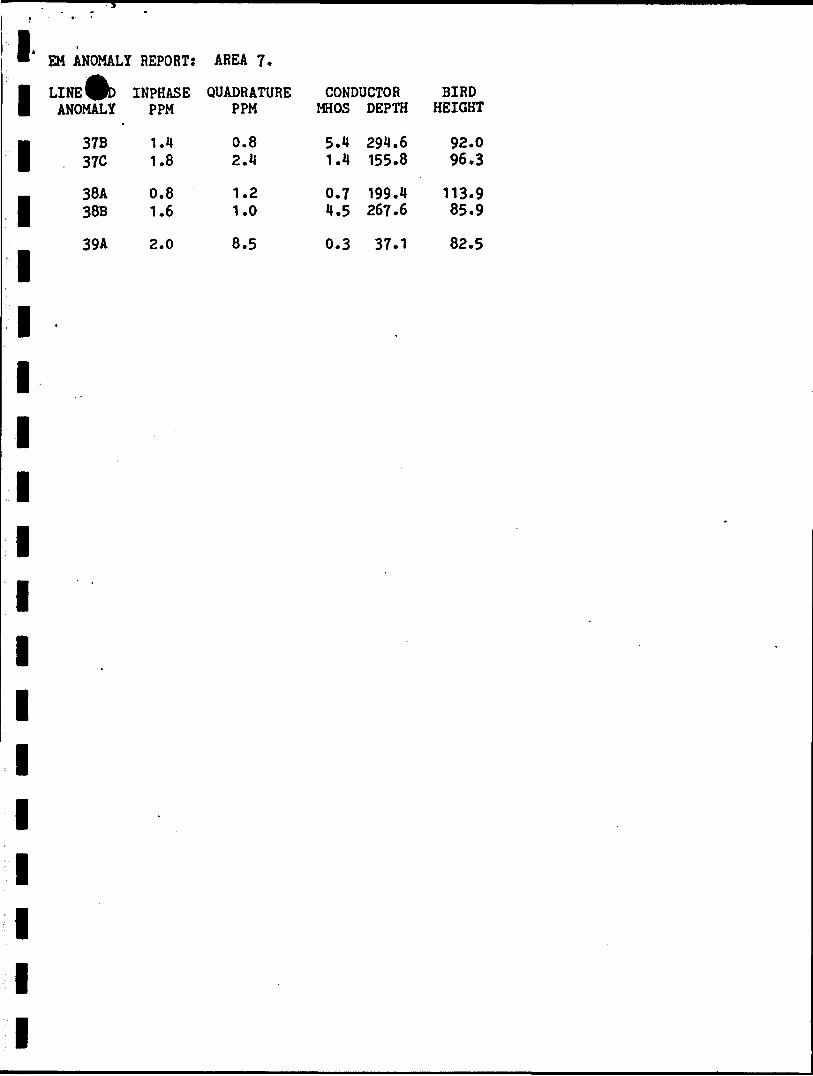
"' EM ANOMALY REPORT: AREA 7.
I LINE0D INPHASE QUADRATURE ANOMALY PPM PPM
I 37B 1.1 0.8 37C 1.8 2.14
- 38A 0.8 1.2 1 38B 1.6 1.0
39A 2.0 8.5
11111111111111
CONDUCTOR BIRD MHOS DEPTH HEIGHT
5.1 291.6 92.0 1.1 155.8 96.3
0.7 199.1 113.9 1.5 267.6 85.9
0.3 37.1 82.5
f
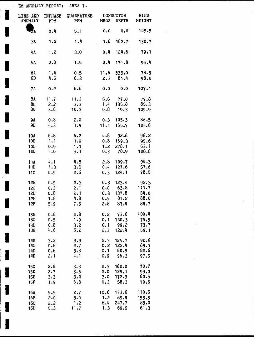
1111111111iiiiiiiii
, EM ANOMALY
LINE AND, ANOMALY
t.3A
HA
5A
6A6B
7A
8A 858C
9A9B
10A10B10C10D
11A11B 11C
12B 12C12D12E12F
13B13C13D13E
14B14C14D14E
15C15D 15E15F
16A16B16C 16D
REPORT:
INPHASEPPM
0.4
1.2
1.2
0.8
1.411.6
0.2
11.7 2.23.8
0.84.3
6.81.10.91.0
4.11.3 0.9
0.9 0.30.81.85.9
0.80.50.84.6
3.20.80.62.1
2.82.7 3.31.9
5.52.02.2 5.3
AREA 7.
QUADRATUREPPM
5.1
1.43.0'
1.5
0.56.3
6.6
11.3 3.3
10.3
2.01.9
6.21.91.13.1
4.83.5 2.6
2.3 2.12.14.87.5
2.81.93.26.2
3.92.73.84.1
3.33.5 3.46.8
2.73.11.2
11.7
CONDUCTORMHOS
0.0
1.6
0.4
0.4
11.62.3
0.0
5.6 1.40.8
0.311.1
4.80.81.20.3
2.80.4 0.3
0.3 0.00.30.52.8
0.20.10.12.3
2.30.20.10.9
2.32.0 3.00.3
10.61.26.4 1.3
DEPTH
0.0
182.7
124.6
174.8
333.081.4
0.0
77.0 135.819.3
145.3165.7
92.6169.3278.178.9
109.7127.6 124.1
123.4 63.8
137.881.287.4
73.6140.399.2
122.4
125.7122.460.596.3
160.0124.1 172.358.3
133.669.4
247.7 69.5
BIRDHEIGHT
145.5
130.7
79.1
95.4
78.398.2
107.1
77.8 85.3
109.9
86.5104.6
98.295.653.1
108.6
94.357.6 78.5
92.3 111.784.088.084.7
109.474.573.759.1
92.669.182.697.5
70.799.0 60.579.6
110.5153.583.0 61.3
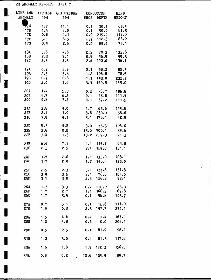
11111111111111111111
EM ANOMALY
LINE ANDANOMALY"c
17D17E17F 17G
18A 18B18C
19A19B19C19D
20A20B 20C
2U21B21C
22D22E22F
23B23C
24B24C
25B25C25D
26 A26B26C
27A27B
28A28B
29B
31B
33A
34A
REPORT:
INPHASEPPM
1.71.40.85.1 0.11
3.6 2.32.5
0.72.30.72.0
1.44.3 0.8
2.82.43.9
4.32.53.4
6.92.3
1.71.7
2.53.43.1
1.31.71.7
0.71.0
1.51.2
0.5
1.2
1.6
0.8
AREA 7.
QUADRATUREPPM
11.18.01.16.5. 2.6
4.6 7.12.5
2.93.80.81.6
5.36.2 3.2
4.01.94.1
4.80.81.3
7.12.5
2.62.0
2.33.53.8
3.32.73.5
5.10.8
4.44.8
2.5
3.0
1.8
0.2
CONDUCTORMHOS
0.10.10.92.7 0.0
2.3 0.52.6
0.11.21.13.3
0.22.1 0.1
1.73.83.1
3.013.613.2
4.12.4
1.11.7
3.13.12.3
0.41.10.7
0.12.3
0.40.2
0.1
0.4
1.9
12.6
DEPTH
30.130.0
215.9112.3 89.9
70.3 46.5
122.0
98.2126.8143.0159.8
38.768.8 57.2
65.6230.0175.1
75.5300.1259.3
115.7129.0
135.0148.4
137.876.6
126.2
110.2166.396.8
12.6147.7
1.40.0
81.9
81.3
132.3
424.9
BIRDHEIGHT
65.481.3
117.268.2 75.1
133.6 95.3
136.1
80.378.5
232.3145.0
106.8111.4 111.5
144.856.642.9
128.639.541.3
64.8131.1
103.1125.0
131.3154.692.1
86.069.8
103.7
111.0236.1
167.4206.1
96.4
117.8
156.5
89.7
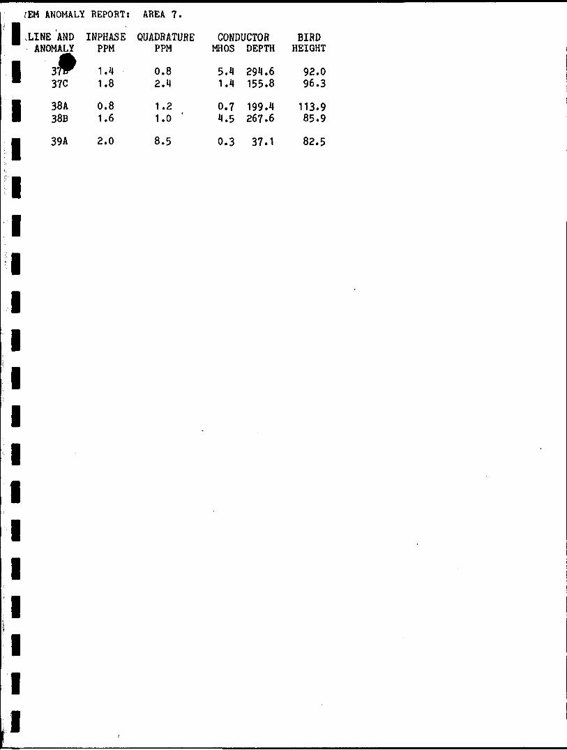
f EM ANOMALY REPORT: AREA 7.
1 .LINE AND INPHASE QUADRATURE CONDUCTOR ANOMALY PPM PPM MHOS DEPTH
1 lW 1 .4 0.8 5.1 294.6 m 37C 1.8 2.4 1.4 155.8
I 38A 0.8 1.2 0.7 199.4 38B 1.6 1.0 4.5 267.6
m 39A 2.0 8.5 0.3 37.1
1
1
1
1
1
1
1
1
1
1
1
1s K
i i
BIRD HEIGHT
92.0 96.3
113.9 85.9
82.5
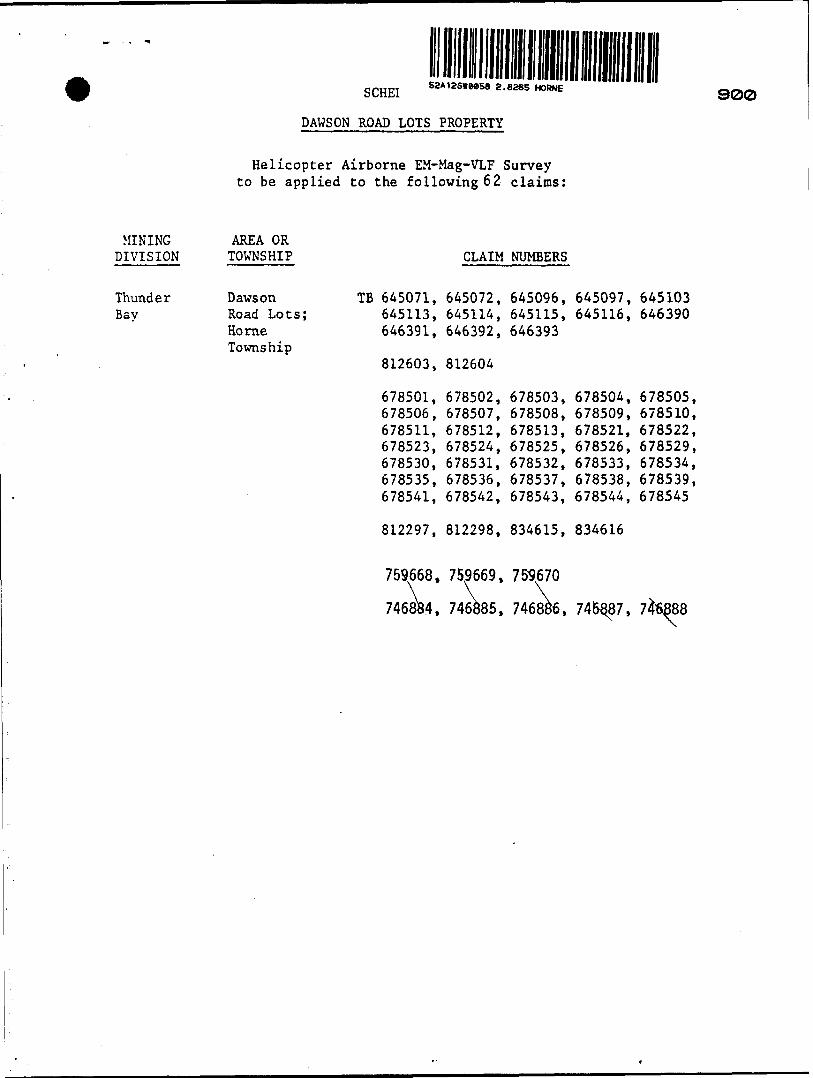
S8A12SWM58 8 .6285 HORNESCHE1
DAWSON ROAD LOTS PROPERTY
900
MINING DIVISION
Thunder Bav
Helicopter Airborne EM-Mag-VLF Survey to be applied to the following 62 claims:
AREA ORTOWNSHIP
DawsonRoad Lots;HorneTownship
TB 645071,645113,646391,
812603,
678501,678506,678511,678523,678530,678535,678541,
CLAIM
645072,645114,646392,
812604
678502,678507,678512,678524,678531,678536,678542,
NUMBERS
645096,645115,646393
678503,678508,678513,678525,678532,678537,678543,
645097,645116,
678504,678509,678521,678526,678533,678538,678544,
645103646390
678505,678510,678522,678529,678534,678539,678545
812297, 812298, 834615, 834616
759668, 759669, 759,670
746884, 746885, 746886, 746Q87, 71688)
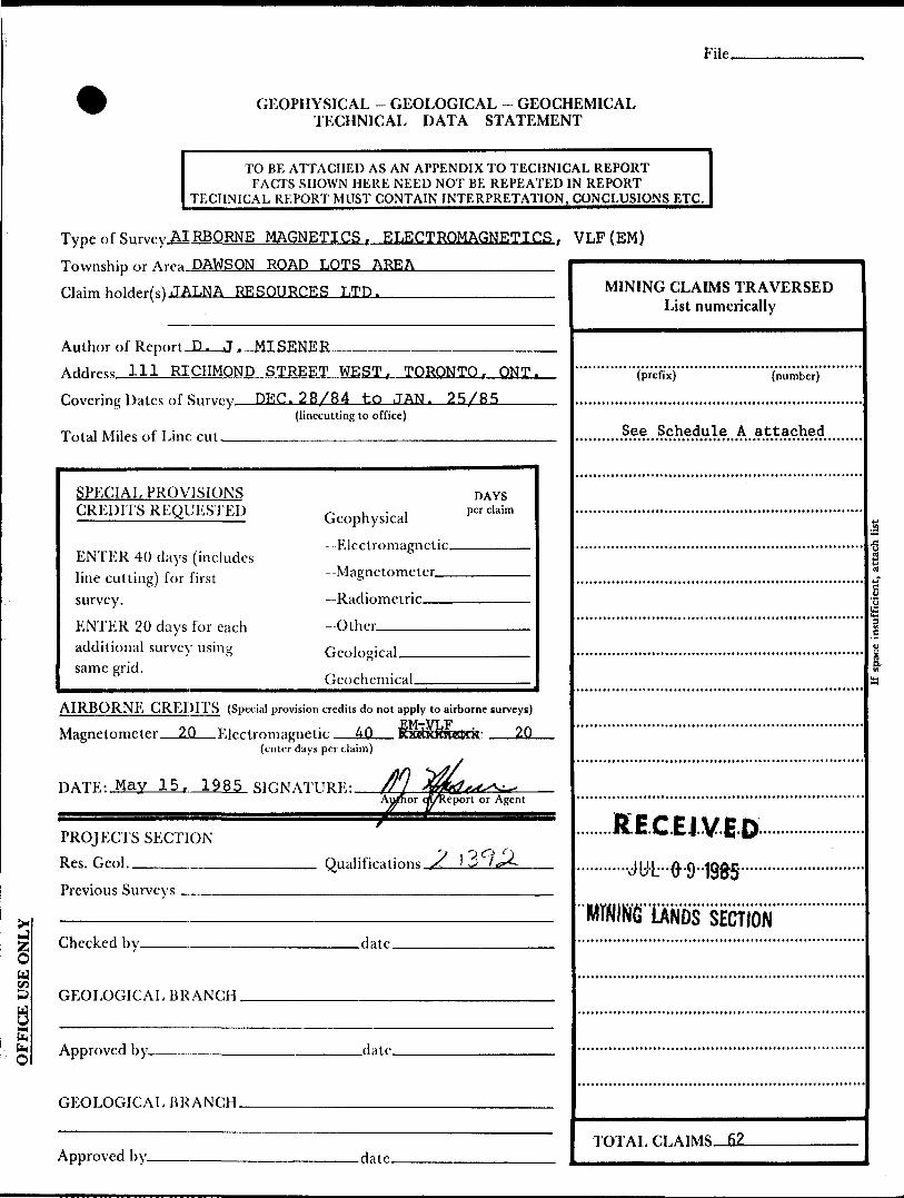
File.
gW 75 S
l(KO
GEOPHYSICAL - GEOLOGICAL - GEOCHEMICAL TECHNICAL DATA STATEMENT
TO BE ATTACHED AS AN APPENDIX TO TECHNICAL REPORTFACTS SHOWN HERE NEED NOT BE REPEATED IN REPORT
TECHNICAL REPORT MUST CONTAIN INTERPRETATION, CONCLUSIONS ETC.
Type of Survey AIRBORNE MAGNETICS,, ELECTROMAGNETICS, VLF (EM) Township or Area DAWSON ROAD LOTS AREA————————Claim hnlrWM JALNA RESOURCES LTD.________________
Author of Rf port D. J. MTSKNRR
111 RICHMOND STREET WEST. TORONTO, ONT. Covering Dates of SnrWy DEC. 28/84 to JAN. 25/85
(linccutting to office)
Total Miles of Line cut—^^—————————-——-———————————
SPECIAL PROVISIONS CREDITS REQUESTED
ENTER 40 days (includes line cutting) for first survey.
ENTER 20 days for each additional survey using same grid.
Geophysical --Electromagnetic.
DAYS per claim
—Radiometric
-Other —Geological.
Geochemical.
AIRBORNE CREDITS (Special provision credits do not apply to airborne surveys)- - . p.M~Vi . n - -
Mftgnptnmcter 20 F.)prtrnmaprietu: 40(enter days per claim)
nATF.- May 15. 1985 SIHNATITRF- fljAupio
PROJECTS SECTION Res. Geol._______ Qualifications /t -
Previous Surveys -.
Checked by. .date.
GEOLOGICAL BRANCH .
Approved by. .date.
GEOLOGICAL BRANCH.
Approved by. -date.
MINING CLAIMS TRAVERSED List numerically
(prefix) (number)
See Schedule A attached
e-S!
RECEIVED
TOTAL- n. 62

Show instrument technical data in each space for type of survey submitted or indicate "not applicable"
GEOPHYSICAL TECHNICAL DATA
)UND SURVEYS
Number of Stations______________________________Number of Readings. Station interval———————————-——-—————^————-^—^^————-—^—————-
Line spacing^—-^^^^^^^——-.^..^^-^.—^-.-^.-^-—.^^----------^..^^—^-----^—^--———.Profile scale or Contour intervals -——-——-—————————..—-.^—^^—...—.^—.—.—.
(specify for each type of survey)
MAGNETIC
Instrument ________________________________'.- ^
Accuracy - Scale constant —
Diurnal correction method.
Base station location—-—-
ELECTROMAGNETIC
Instrument______Coil configuration,— Coil separation ———.
Accuracy-—————
Method: EH Fixed transmitter tU Shoot back D In line D Parallel line
Frequency———-—--—-———.^^^—————-——-——.———-———.———^—————.——-^-—————^-—.——(specify V.L.F. station)
Parameters measured -————————————^————-——^—-——.———-———-^—-—-——-^-——————-——GRAVITY
Instrument.
Scale constant
Corrections
Base station value and location.
Elevation accuracy———————.—.—^^—^^———INDUCED POLARIZATION RESISTIVITY
Instrument-^——...——-.^-^—-——-—.—.^—Time domain___________________________ Frequency domain. Frequency_____________________________ Range—.-—-^——Power—————-^———————-^————.-——^—^—-—--—-—^-^————-^--—-Electrode array——
Electrode spacing. Type of electrode .
SELF POTENTIAL
Instrument_________________________________________ Range.Survey Method ,———^——-—.————.———^——.^———^—^—^-^—.^———-——
Corrections made.
RADIOMETRIC
Instrument —^——Values measured.
Energy windows (levels) ——-—————————.^-.^—————.—.———————.^———
Height of instrument____________________________Background CountSize of detector-—-———^———^—^————————...—.—..——...—.^^—..—^—...—^^
Overburden ————-———————^——..-^—..—..——^..^^^——-^————^^.—.—^—(type, depth — include outcrop map)
OTHERS (SEISMIC, DRILL WELL LOGGING ETC.)
Type of survey———————-———————-—^———^—Instrument ——^-—.—^—^————--———^———— Accuracy-—^————-——.-^^————^———^-—Parameters measured.
Additional information (for understanding results).
AIRBORNE SURVEYSType of giitwy(g) MAGNETICS. ELECTROMAGNET! C.R , VT/P PT^r-rppQMAGNETICS—--——————-——Instrument(s) Geometrics 803 Mag. Hertz Totem 2A-VLF. Geotech EMEX-1. 4 Freq. A.E.M
. (specify for each type of survey) iAccurac (Magnetics) ±1 nanotesla, (AEM) i . 5ppn (IP and QUAD), (VLF) I J.% Total field and quad.
(specify for each type of survey)Aircraft n,pH Bell 206-B helicopter OFAIR—-—^————-——-—^—-—————
Sensor altitude EM - 100 feet, MAGNETICS AND VLF - 150 feet_________^____^_Navigation and flight path recovery method Visual navigation from airphoto mosaics.____
o o r J
_____Geotech Video Datacom flight path recovery.——^-^————————————.Aircraft altitnHp 200 feet_____________________Line Sparing 660 feet——.—————
Miles flown over total arpa 7 fi_____________________Over claims only____2L6____________
GEOCHEMICAL SURVEY ~ PROCEDURE RECORD
Numbers of claims from which samples taken.
Total Number of Samples. Type of Sample.
(Nature of Material)
Average Sample Weight-—^———— Method of Collection——-——^——
Soil Horizon Sampled. Horizon Development. Sample Depth————Terrain^—————.—
Drainage Development——^————————
Estimated Range of Overburden Thickness.
ANALYTICAL METHODS
Values expressed in: per cent p. p. m. p. p. b.
n o nCu, Pb, Zn,
Others————
Ni, Co, Ag, Mo, As,-(circle)
Field AnalysisExtraction Method. Analytical Method-
Reagents Used ——Field Laboratory Analysis
No. ..———————-—
SAMPLE PREPARATION(Includes drying, screening, crushing, ashing)
Mesh size of fraction used for analysis ————
Extraction Method. Analytical Method - Reagents Used ——
Commercial Laboratory (. Name of Laboratory-—
Extraction Method-
Analytical Method ——
Reagents Used————
.tests)
.tests)
.tests)
General. General.
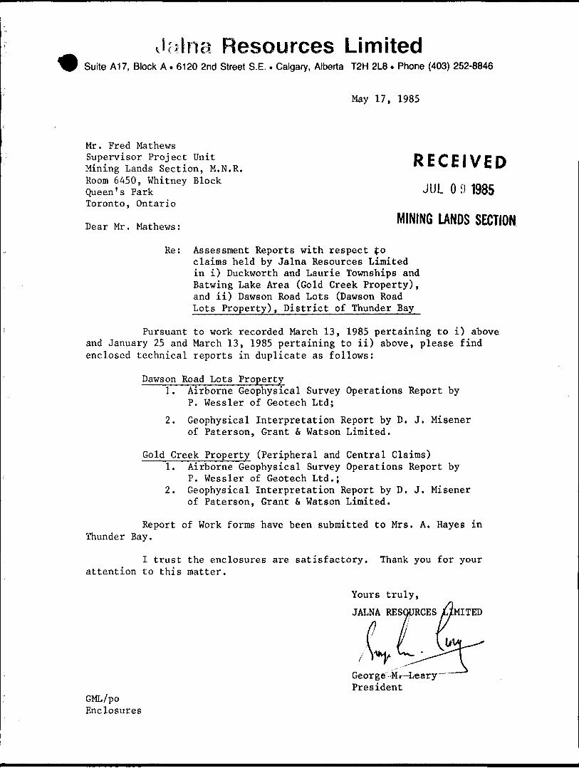
Jcilna Resources LimitedSuite A17, Block A . 6120 2nd Street S.E.. Calgary, Alberta T2H 2L8 . Phone (403) 252-8846
May 17, 1985
Mr. Fred MathewsSupervisor Project UnitMining Lands Section, M.N.R.Room 6450, Whitney Block l tlt nQueen's Park JUL O 1) 1985Toronto, Ontario
Dear Mr. Mather: M INING WU* SECTION
Re: Assessment Reports with respect foclaims held by Jalna Resources Limited in i) Duckworth and Laurie Townships and Batwing Lake Area (Gold Creek Property), and ii) Dawson Road Lots (Dawson Road Lots Property), District of Thunder Bay
Pursuant to work recorded March 13, 1985 pertaining to i) above and January 25 and March 13, 1985 pertaining to ii) above, please find enclosed technical reports in duplicate as follows:
Dawson Road Lots Property1. Airborne Geophysical Survey Operations Report by
P. Wessler of Geotech Ltd;
2. Geophysical Interpretation Report by D. J, Misener of Paterson, Grant (t Watson Limited.
Gold Creek Property (Peripheral and Central Claims)1. Airborne Geophysical Survey Operations Report by
P. Wessler of Geotech Ltd.;2. Geophysical Interpretation Report by D. J. Misener
of Paterson, Grant St Watson Limited.
Report of Work forms have been submitted to Mrs. A. Hayes in Thunder Bay.
I trust the enclosures are satisfactory. Thank you for your attention to this matter.
Yours truly,
JALNA RESOURCES /JMITED
Geor ge --M r -Leary" President
GML/po Enclosures
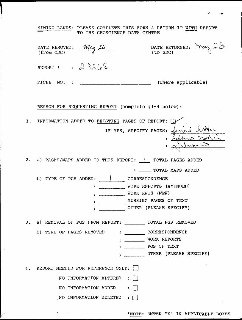
MINING LANDS; PLEASE COMPLETE THIS FORM fi, RETURN.IT WITH REPORT ~~TO THE GEOSCIENCE DATA CENTRE
DATE REMOVED: WM / 6* DATE RETURNED: __ (from GDC) -— ,-y-- {to GDC)
REPORT # : cS . ^ A [j ̂
PICHE NO. : ———.—————————.—— (where applicable)
REASON FOR REQUESTING REPORT (complete #1-4 below):
1. INFORMATION ADDED TO EXISTING PAGES OF REPORT:
IF YES, SPECIFY PAGES:
X
2. a) PAGES/MAPS ADDED TO THIS REPORT: -J _ TOTAL PAGES ADDED
: ____ TOTAL MAPS ADDED
b) TYPE OF PCS ADDED: l CORRESPONDENCE
: ________ WORK REPORTS (AMENDED)
j ________ WORK RPTS (NEW)
. ________ MISSING PAGES OF TEXT
: ________ OTHER (PLEASE SPECIFY)
3. a) REMOVAL OF PCS FROM REPORT: ______ TOTAL PCS REMOVED
b) TYPE OF PAGES REMOVED : ______ CORRESPONDENCE
. ______ WORK REPORTS
: ______ PCS OF TEXT
: OTHER (PLEASE SPECIFY)
4. REPORT NEEDED FOR REFERENCE ONLY:
NO INFORMATION ALTERED : f]
NO INFORMATION ADDED :
NO INFORMATION DELETED :
*NOTE: ENTER "X" IN APPLICABLE BOXES
May 28, 1987 Your File: 139 Our File: 2.8265
Mining RecorderMinistry of Northern Developnent and Mines435 Oames Street SouthP.O. Box 5000Thunder Bay, OntarioP7C 566
Dear Madam:RE: Notice of Intent dated August 27, 1985
Geophysical (Electromagnetic,Magnetometer ft VLF) Surveys on Mining Claims TB 645071, et al. In Horne Township
The assessment work credits, as listed with the above-mentioned Notice of Intent, have been approved as of the above date.
Please Inform the recorded holder of these mining claims and so Indicate on your records.
Yours sincerely,
Gary L. Heatherson, Manager Mining Lands Section Mineral Development and Lands Branch Mines and Minerals Division
Whitney Block, Room 6610 Queen's Park Toronto, Ontario M7A 1H3
Telephone: (416) 965-4888
AB/mccc: Mr. G.H. Ferguson
Mining fi Lands CommissionerToronto, Ontario
ano
Ministry ofNaturalResources
1985 08 27 Your File: #139 Our File; 2.8265
Mining RecorderMinistry of Natural ResourcesP.O. Box 5000Thunder Bay, OntarioP7C 5G6
Dear Madam:
Enclosed are two copies of a Notice of Intent with statements listing a reduced rate of assessment work credits to be allowed for a technical survey. Please forward one copy to the recorded holder of the claims and retain the other. In approximately fifteen days from the above date, a final letter of approval of these credits will be sent to you. On receipt of the approval letter, you may then change the work entries on the claim record sheets.For further information, if required, please contact Mr. R.J. Pichette at 416/965-4888.
-Ypurs sincerely,
IS.E.yYundt*ctor
Land Management Branch
Whitney Block, Room 6643 Queen's Park Toronto, Ontario M7A 1W3
fi,t-D. I sherwood:me
Encls.
cc: Jalna Resources Limited Calgary, Alberta
cc: Daniel Calvert Muri!lo, Ontario
cc: Jim MisenerToronto, Ontario
cc: Mr. G.H. FergusonMining b Lands CommissionerToronto, Ontario
845
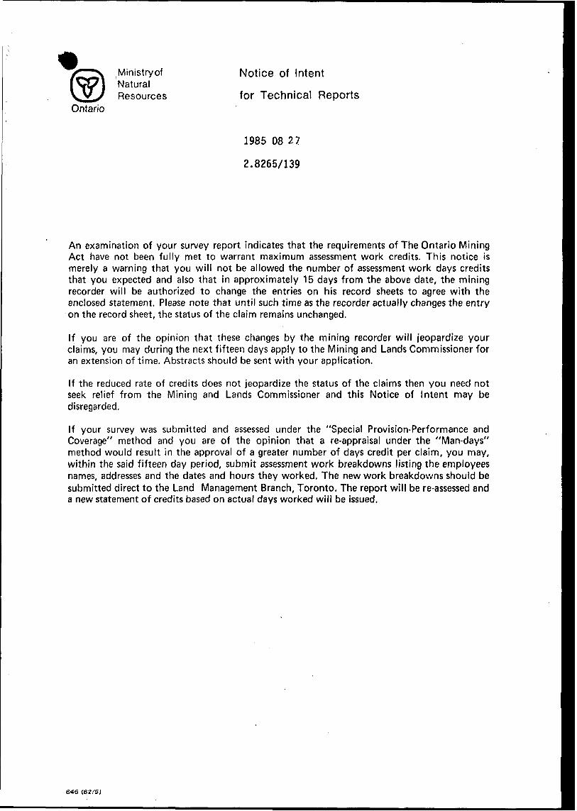
Ministry ofNaturalResources
Ontario
Notice of Intent
for Technical Reports
1985 08 27
2.8265/139
An examination of your survey report indicates that the requirements of The Ontario Mining Act have not been fully met to warrant maximum assessment work credits. This notice is merely a warning that you will not be allowed the number of assessment work days credits that you expected and also that in approximately 15 days from the above date, the mining recorder will be authorized to change the entries on his record sheets to agree with the enclosed statement. Please note that until such time as the recorder actually changes the entry on the record sheet, the status of the claim remains unchanged.
If you are of the opinion that these changes by the mining recorder will jeopardize your claims, you may during the next fifteen days apply to the Mining and Lands Commissioner for an extension of time. Abstracts should be sent with your application.
If the reduced rate of credits does not jeopardize the status of the claims then you need not seek relief from the Mining and Lands Commissioner and this Notice of Intent may be disregarded.
If your survey was submitted and assessed under the "Special Provision-Performance and Coverage" method and you are of the opinion that a re-appraisal under the "Man-days" method would result in the approval of a greater number of days credit per claim, you may, within the said fifteen day period, submit assessment work breakdowns listing the employees names, addresses and the dates and hours they worked. The new work breakdowns should be submitted direct to the Land Management Branch, Toronto. The report will be re-assessed and a new statement of credits based on actual days worked will be issued.
646
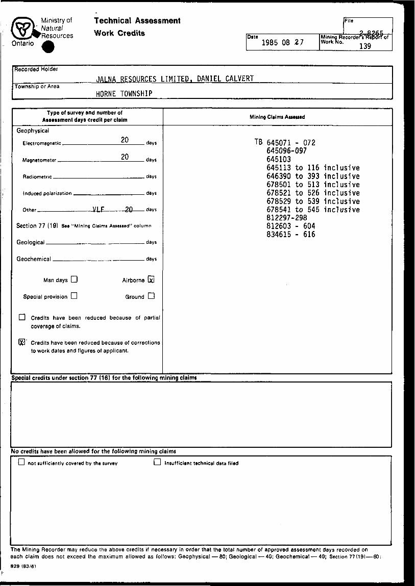
Ministry of ^ Natural
'ResourcesOntario
Technical Assessment Work Credits Date
1985 08 27
File
oMining Recorder"*? Work No.
1 *3
OOJtCWffi9
of
Recorded Holder
Township or AreaJALNA RESOURCES LIMITED,
HORNE TOWNSHIP
DANIEL CALVERT
Type of survey and number of Assessment days credit per claim
Geophysical20 Electromagnetic ..r.
20Mflgnetnmptpr t- u
Radiometric ....
Inrinrarl pnlarijatinn
n.h.r VLF 20
days
days
days
days
days
Section 77 (19) See "Mining Claims Atiesied" column
Geological .-..-
fienrhemiral
Man days CD Airborne
Special provision CD Ground
days
days
D
fi Credits have been reduced because of partial
coverage of claims.
QCl Credits have been reduced because of corrections
to work dates and figures of applicant.
Mining Claim* Assessed
TB 645071 - 072645096-097645103645113 to 116646390 to 393678501 to 513678521 to 526678529 to 539678541 to 545W/ W hs*t J. vv *J^ +J
812297-298812603 - 604834615 - 616
inclusive jnrl usi VPIIIOIUOIVC
inclusiveinrl usi VPIIIWI U d 1 TV
inclusiveinclusive
Special credits under section 77 (16) for the following mining claims
No credits have been allowed for the following mining claims
D not sufficiently covered by the survey D Insufficient technical data filed
The Mining Recorder may reduce the above credits if necessary in order that the total number of approved assessment days recorded on each claim does not exceed the maximum allowed as follows: Geophysical 80; Geological 40; Geochemical 40; Section 77(19) 60:
828 (83/6)
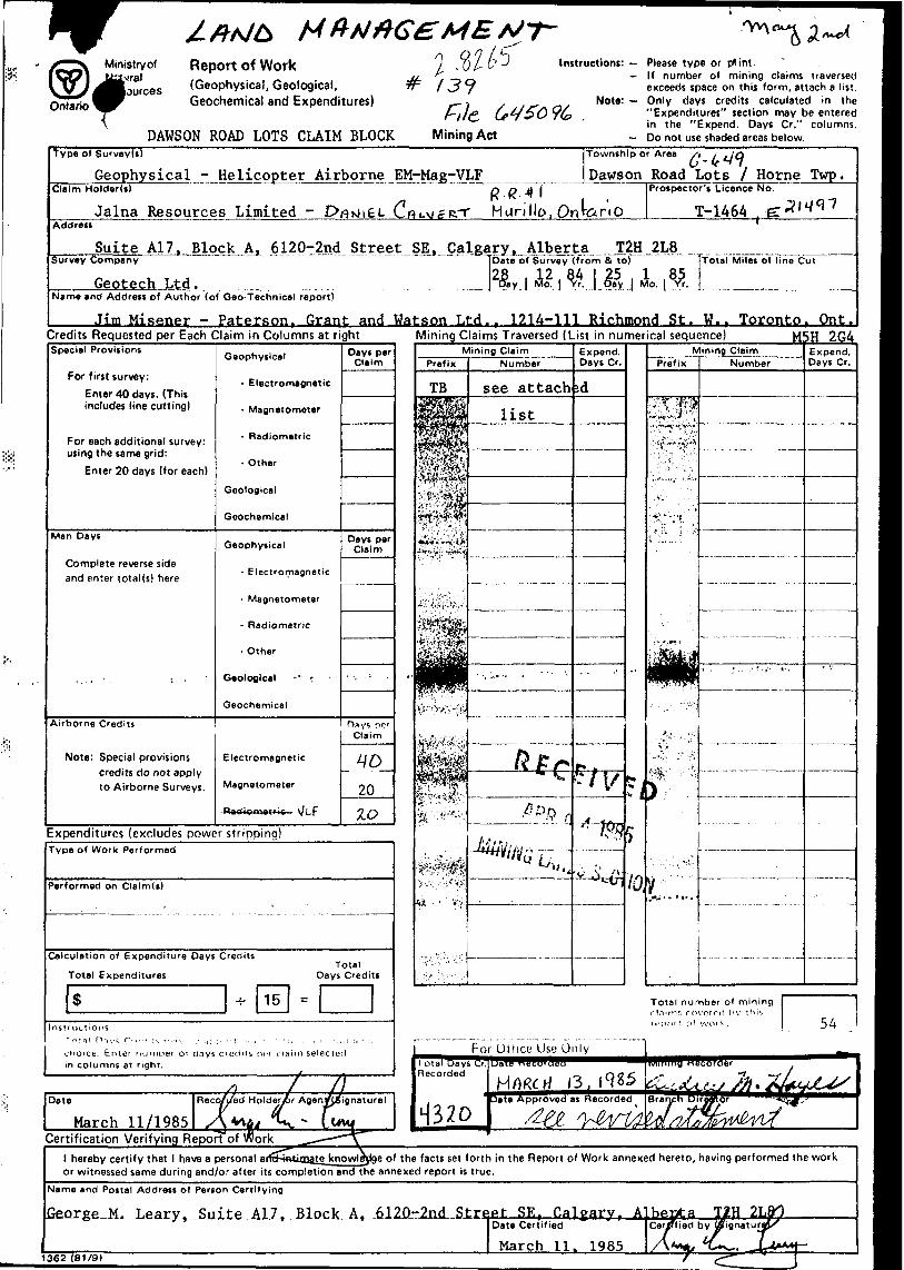
Ministry of .vral lources
Ontariof,
Report Of Work
(Geophysical, Geological, Geochemical and Expenditures)
DAWSON ROAD LOTS CLAIM BLOCK
y ."O/- t' ~^ I nstruction*: Please type or tfint. ^ -If number of mining claims traversedl .j y e xceeds space on this form, attach a list.
. Note: Only days credits calculated in thef-ll(* Ce^i SO *?b " Expenditures" section may be entered
'in the "Expend. Days Cr." columns.Mining Act - Do not use shaded areas below.
Type of Survey!*)
___Geophysical - Helicopter Airborne^EM-Mag-VLF^Claim Holderd)
Township or Area /i i jjq
Dawson Road Lots l Horne Twp.
Jalna Resources Limited - COLA/CRT Hurillo,
Prospector's Licence No,
Address
Suite A17. Block A. 612p^-2ndSurvey Company
Geotech Ltd.
.^of Survey (from Si to) Total Miles of line Cut
Name and Address of Author (of Geo-Technical report)
___Jim Misener - Paterson. Grant and Watson Ltd.. 1214-111 Richmond St. W.. Toronto. Ont.Credits Requested per Each Claim in Columns at rightSpecial Provisions
For first survey:
Enter 40 days. (This includes line cutting)
For each additional survey: using the same grid:
Enter 20 days (for each)
Man Days
Complete reverse side and enter total (s) here
Airborne Credits
Note: Special provisions credits do not apply to Airborne Surveys.
Geophysical
- Electromagnetic
- Magnetometer
- Radiometric
- Other
Geological
Geochemical
Geophysical
- Electromagnetic
- Magnetometer
- Radiometric
- Other
Geological - ' :
Geochemical
Electromagnetic
Magnetometer
Rodiometric - V/Lp
Days perClaim
Days per Claim
Hays pp' Claim
-4P-
20
10
Mining Claims Traversed (List in numerical sequence) M5H 2G4
Expenditures (excludes power stripping)Type of Work Performed
Performed on Claim(t)
Calculation of Expenditure Days Credits
Total Expenditures
S -7-15
Instructions1 r. r. il OTVS r ,,,,,.;,-. r ,,.,,. ,, ,,.,., ,, ., ; , , ,- .
choice. Enter nuniDer oi days credits KT c la in columns at right.
Total Days Credits
=
m selected
j
Date
March 11/1985Recc/j/ed Holde&r Agen/Jsignature)
Certification Verifying Report of work
Total number of m ining.iimr, rnvoroc! hv this
l hereby certify that l have a personal arfj^akiim^to knowledge of the facts set forth in the Report of Work annexed hereto, having performed the work or witnessed same during and/or after its completion and the annexed report is true.
Name and Postal Address of Person Certifying
George M. ̂ ^ .Suite -All, , nl2f)-2nd Street SE r Cal earv r Albepta T2H 21
1362 (81/9)
Date Certified ' ICer/Tfied by
March 11, 1985
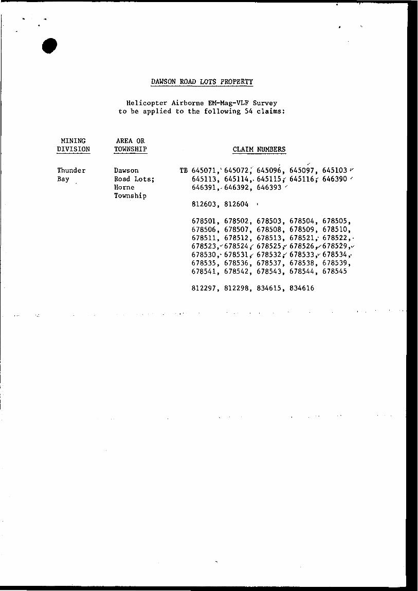
DAWSON ROAD LOTS PROPERTY
MINING DIVISION
Thunder Bay
Helicopter Airborne EM-Mag-VLF Survey to be applied to the following 54 claims:
AREA OR TOWNSHIP CLAIM NUMBERS
DawsonRoad Lots;HorneTownship
TB 645071, '645113,646391,-
812603,
678501,678506,678511,678523,'678530,-678535,678541,
645072,'645114,.646392,
812604
678502,678507,678512,678524 ,'678531,-678536,678542,
645096,645115,"646393 '
i
678503,678508,678513,678525,^678532,'678537,678543,
645097,645116 r
678504,678509,678521,-
645103 '646390 -
678505,678510,678522,
678526^678529,678533,-678538,678544,
678534,-678539,678545
812297, 812298, 834615, 834616
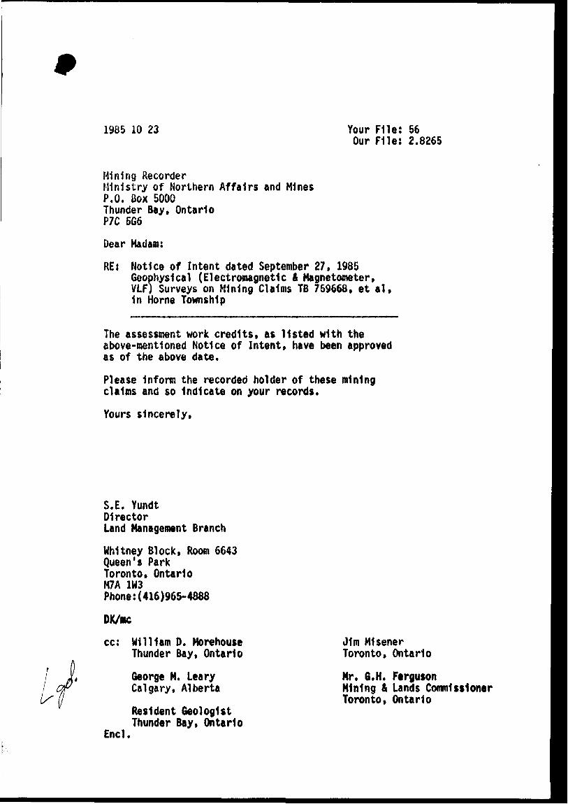
1985 10 23 Your File: 56 Our File: 2.8265
Mining RecorderMinistry of Northern Affairs and MinesP.O. Box 5000Thunder Bay, OntarioP7C 5G6
Dear Madam:
RE: Notice of Intent dated September 27, 1985 Geophysical (Electromagnetic 4 Magnetometer, VLF) Surveys on Mining Claims TB 759668. et al, 1n Horne Township
The assessment work credits, as listed with the above-mentioned Notice of Intent, have been approved as of the above date.
Please Inform the recorded holder of these mining claims and so Indicate on your records.
Yours sincerely,
S.E. YundtD1rectorLand Management Branch
Whitney Block, Room 6643 Queen's Park Toronto, Ontario M7A 1M3 Phone:(416)965-4888
DK/ac
cc
Encl.
William 0. Morehouse Thunder Bay, Ontario
George M. Leary Calgary, Alberta
Resident Geologist Thunder Bay, Ontario
J1m Misener Toronto, Ontario
Nr. 6.H. FergusonMining 4 Lands CommissionerToronto, Ontario

MinistryofNaturalResources
Ontario
Notice of Intent
for Technical Reports
1985 09 27
2.8265/56
An examination of your survey report indicates that the requirements of The Ontario Mining Act have not been fully met to warrant maximum assessment work credits. This notice is merely a warning that you will not be allowed the number of assessment work days credits that you expected and also that in approximately 15 days from the above date, the mining recorder will be authorized to change the entries on his record sheets to agree with the enclosed statement. Please note that until such time as the recorder actually changes the entry on the record sheet, the status of the claim remains unchanged.
If you are of the opinion that these changes by the mining recorder will jeopardize your claims, you may during the next fifteen days apply to the Mining and Lands Commissioner for an extension of time. Abstracts should be sent with your application.
If the reduced rate of credits does not jeopardize the status of the claims then you need not seek relief from the Mining and Lands Commissioner and this Notice of Intent may be disregarded.
If your survey was submitted and assessed under the "Special Provision-Performance and Coverage" method and you are of the opinion that a re-appraisal under the "Man-days" method would result in the approval of a greater number of days credit per claim, you may, within the said fifteen day period, submit assessment work breakdowns listing the employees names, addresses and the dates and hours they worked. The new work breakdowns should be submitted direct to the Land Management Branch, Toronto. The report will be re-assessed and a new statement of credits based on actual days worked will be issued.
846 ( 82/5)
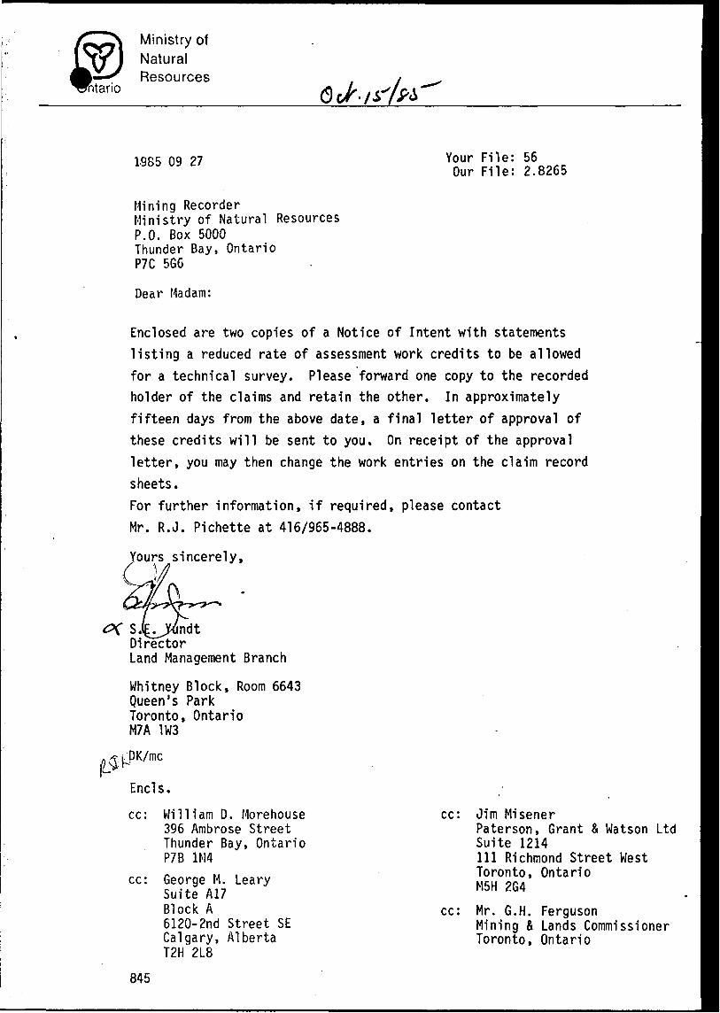
ritario
Ministry ofNaturalResources
L985 09 27
Mining RecorderMinistry of Natural ResourcesP.O. Box 5000Thunder Bay, OntarioP7C 5G6
Dear Madam:
Your File: 56 Our File: 2.8265
Enclosed are two copies of a Notice of Intent with statements listing a reduced rate of assessment work credits to be allowed for a technical survey. Please forward one copy to the recorded holder of the claims and retain the other. In approximately fifteen days from the above date, a final letter of approval of these credits will be sent to you. On receipt of the approval letter, you may then change the work entries on the claim record sheets.For further information, if required, please contact Mr. R.J. Pichette at 416/965-4888.
ours sincerely,
S.lE^OndtDirectorLand Management Branch
Whitney Block, Room 6643 Queen's Park Toronto, Ontario M7A 1W3
DK/mc
Ends.
cc: William D. Morehouse 396 Ambrose Street Thunder Bay, Ontario P7B 1M4
cc: George M. Leary Suite A17 Block A6120-2nd Street SE Calgary, Alberta T2H 2L8
cc: Jim MisenerPaterson, Grant fc Watson LtdSuite 1214111 Richmond Street WestToronto, OntarioM5H 2G4
cc: Mr. G.H. FergusonMining fi Lands Commissioner Toronto, Ontario
845
REGISTERED
1985 04 01 Report of Work 156
William D. Morehouse 396 Ambrose Street Thunder Bay. Ontario P7B 1M4
Dear Sir:
Enclosed 1s a copy of a Report of Work for Electromagnetic and Magnetometer assessment work credits that was recorded by the Mining Recorder on January 25* 1985 on Mining Claims TB 759668,1n the Township of Nome.
Me have no record that you provided the full reports and maps to the Minister within the sixty day period provided by Section 77 of the Mining Act.
If the material 1s not submitted to this office by April 12, 1985, I will have no alternative but to Instruct the Mining Recorder to delete the work credits from the claim record sheets.
For further Information, please contact Mr. Arthur Barr at (416)965-4888.
Yours sincerely, ,\
S. E. YundtDirectorLand Management Branch
Whitney Block, Room 6643 Queen's Park Toronto, Ontario M7A 1W3 Phone:(416)965-4888
A. Barrimc
cc: Mining RecorderThunder Bay, Ontario
cc: George M. LearySuite A17Block A6120-2nd Street SECalgary, AlbertaT2H 2L8
End.
cci Jim MisenerPaterson, Grant ft Natson Ltd S8iUel2tl4111 Richmond StreetUest Toronto, Ontario N5H 264
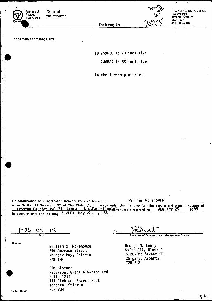
Ministryof Order of*Blurat the Minister Resources
The Mining Act
VQ&&3
Room 6643, Whitney Block Queen'i Park Toronto, Ontario M7A 1W3416/965-4888
In the matter of mining claims:
TB 759668 to 70 inclusive
746884 to 88 inclusive
in the Township of Horne
William MorehouseOn consideration of an application from the recorded holder, ———.———under Section 77 Subsection 22 of The Mining Act, l hereby order that the time for filing reports and plans in support ofAirborne Geophysical (Electromagnetic.Magnetorofct&^nt work recorded on January 25. 1086—
be extended until and inducting R VLF) May 27, 19 85 .
04.Date
Copies:
Signature of Director, Land Management Branch
1333 (85/02)
William D. Morehouse 396 Ambrose Street Thunder Bay, Ontario P7B 1M4
Jim MisenerPaterson, Grant 8 Watson LtdSuite 1214111 Richmond StreetToronto, -OntarioM5H 2G4
West
George M. Leary Suite A17, Block A 6!20-2nd Street SE Calgary, Alberta T2H 2L8
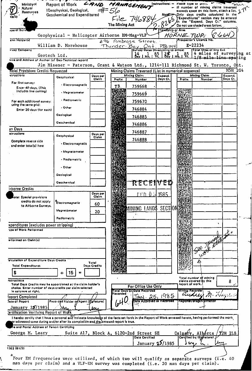
Minlstryol Report of Work
(Geophysical, Geological, Geochemical and Expenditures)
F.ldL- The Mining Act
instructions: nease type vi in mi. H number of mining claims traversed ^
exceeds space on this form, attach a list. \ \ NoifP^spnly days credits calculated in the
('Expenditures" section may be entered the "Expend. Dayt Gr." columns.
Do not use ihadod areas below.
Geophysical - Helicopter Airborne EM-Mag-VLF[ ™
-^— ̂Tj(wnihlp^or Area
Im HoldtrU)
William D. Morehouse"vty Company
"S-freet,^ Bay , On 1. .
Survey D*ui ( llntcuttlng to o((ie*i
Geotech Ltd.
Prospector'! Ucenc* No.
Total Mllei of line Cut4 miles of survey1 I P ~J1~ 1 i ~r.^___________________ __ _ __ ^ _ . .....^ .-_ opt
i m* and Addreii of Author (of Geo-Tachnlcel report)
Jim Misener - Paterson, Grant S Watson Ltd., 1214-111 Richmond St. W. Toronto, O
.ng at ingit.
cial Provisions Credits Requestedutructloni
For first survey:Enter 40 days. (Tnis Includes line culling)
For each additional survey: using the same grid:
Enter 30 days (for each)
Giophyilcil
- Electromagnetic
- Magnttomiur
- Radiometric
- Other
Geological
Oiochemlcal
Dayi per Claim
Mining Claims Traversed (List in numerical sequence) M5H 2G4
an Daysutructloni
Complete reverse side and enter total (s) here
Gaophyilctl
* Electromagnetic
- Magnetometer
- Radiometric i
- Other
Oeologlcal
Geochemical
Dayi par Claim
irborne Credits
lota: Special provisions credits do not apply to Airborne Surveys.
Electromagnetic
Magnetometer
Ridlometrlc
Days perClaim
6020
xpenditures (excludes power stripping)ype of Work Performed
erformed on Clilmd)
'4lculatlon of Expenditure Dayi Credit!
Total Expenditure!
S * 15
Total Deyi Cradlti
B
nstructloni Total Days Creditt may be apportioned at the claim holder'a choke. Enttr number of deyi credlti per claim lelected In columni it right. -
deport CompletedSite of Report
January 2571985Recorded Holder orAgent (
. ljertitication Verifying Report of Weak
-
For Office Use OnlyroteTTSayTCT Recorded -
V&;
Date Recorded
TftM. 55, 1^5-Date Approveo as nacoroao-m '
Tote) number cf claims covered l report of work.
Mining Recorder
nagionai/oraocn
miningthis g
s
fy. K*.y..L.^'director
l hereby certify that l have a personal ancHntlmaie knowledge of the facts tat forth In the Report of Work annexed hereto, having performed the work ir witnessed same during and/or after its completion and^hajinnexed report Is true.
ne end Coital Addreii of Penon Certifying
George M. Leary Suite A17, Block A, 6120-.2nd Street SE Calgary. Al 2H 2L8Date Certified
January l5?19851362(61/2)
Four EM frequencies were utilized, of which two will qualify as separate surveys (i.e. 40 man days per claim) and a VLF-EM survey was completed (i.e. 20 man days per claim).
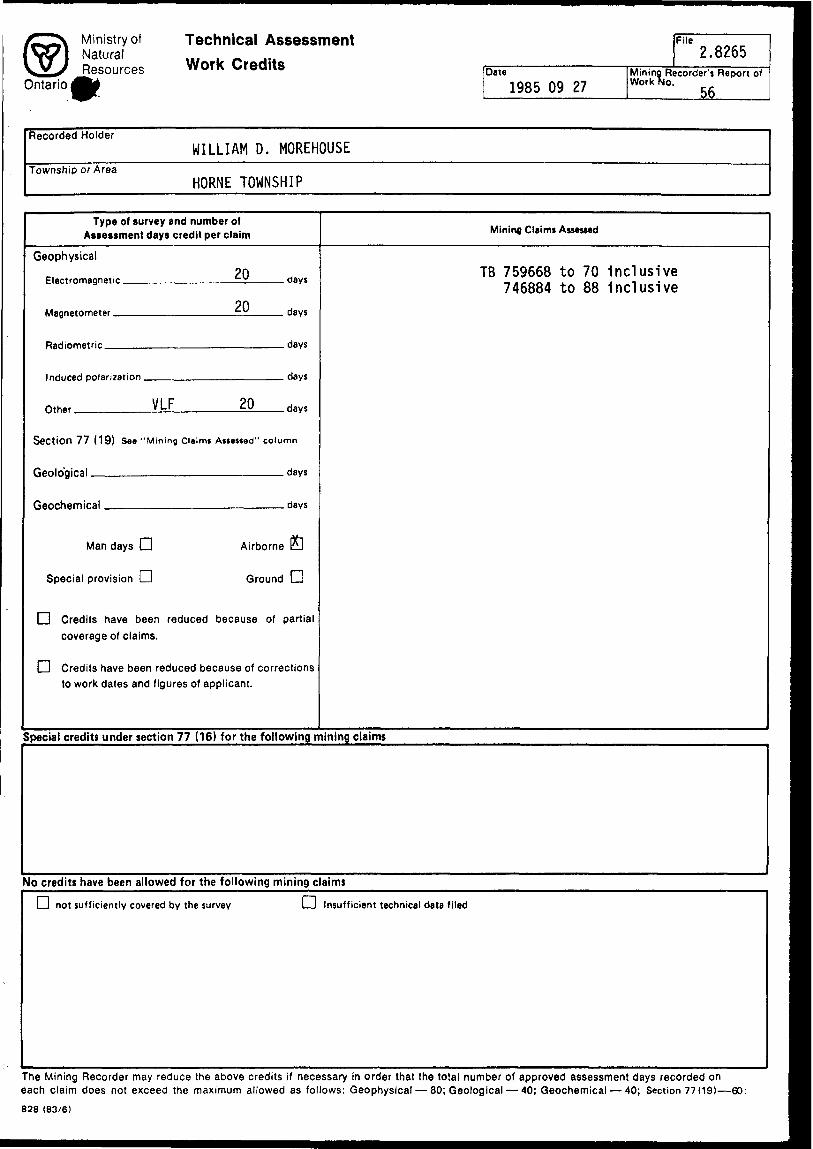
© Ministry of Technical Assess Natural ,. f . . ... Resources WOfk Credits
Ontario ^y
Fl" 2.8365
Date Mining Recorder's Report of1985 09 27 WorkW 5 6
Recorded Holder WILLIAM D. MOREHOUSE
Township or AreaHORNE TOWNSHIP
Type of survey and number of Assessment days credit per claim
Geophysical
onMagnetometer tu days
Rflrlinmetrir days
nth0 , VLF 20 days
Section 77 (19) See "Mining Claims Astested" column
Qonln'giral days
ftervhemiral riavs
Man days LJ Airborne B
Special provision LJ Ground LJ
|~l Credits have been reduced because of partial coverage of claims.
O Credits have been reduced because of corrections to work dates and figures of applicant.
Mining Claims Assessed
TB 759668 to 70 inclusive 746884 to 88 inclusive
Special credits under section 77 (16) for the following mining claims
No credits have been allowed for the following mining claims
ri not sufficiently covered by the survey l —. l Insufficient technical data filed
The Mining Recorder may reduce the above credits if necessary in order that the total number of approved assessment days recorded on each claim does not exceed the maximum allowed as follows: Geophysical — 80; Geological — 40; Geochemical — 40; Section 77(19)—60:
828 (83/6)
Action T Merho
Dale
Pnoned
LJ Hold
Please Call Returned
l l Your Call
Will Call Back —. l _ l Wishes Appointment
pj Waiting pi Willin Person Return
LJ Was Here
DraM Reply For f""| Provide [~] For Your My Signature More Details Information
i—i For Your Approval |—| Keep We '— and Signature
i—i Keep '—' Inlor[~| Type Draft
[~~] Type Final
D Make ____ r—i Return r—i Note and Copies ———— l—' With Comments *—' See M; 1
LJ Per Discussion
l—j Circulate, initial — and Return
Please Answer P] Investigate ' LJ and Report
iflJN 27D Note and i—i
Return !—l
M1N1NG1AMDS
Returned
Comments
7540-1037 (Rev. 11/82)
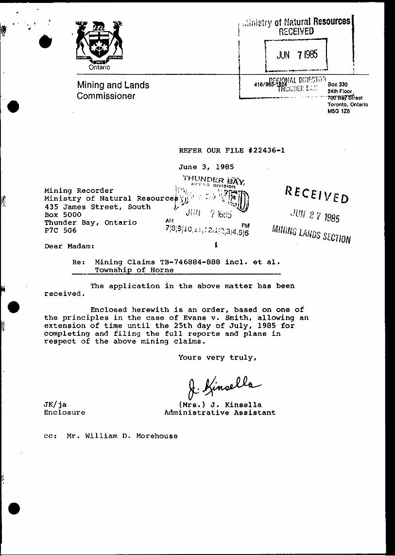
Ontario
r i,'sinisiry of Natural Resources l RECEIVED
JUN 71985
Mining and Lands Commissioner
,. " Box 33024th Floor,
" 'TOCTBairSffeet Toronto, Ontario M5G 1Z6
REFER OUR FILE 122436-1
June 3, 1985
Mining Recorder HMinistry of Natural Resource435 James Street, SouthBox 5000Thunder Bay, OntarioP7C 5G6
Dear Madam:
Re: Mining Claims TB-746884-888 incl. et al. Township of Horne—————-———————-————
received.The application in the above matter has been
2
Enclosed herewith is an order, based on one of the principles in the case of Evans v. Smith, allowing an extension of time until the 25th day of July, 1985 for completing and filing the full reports and plans in respect of the above mining claims.
Yours very truly,
JK/ja Enclosure
(Mrs.) J. Kinsella Administrative Assistant
cc: Mr. William D. Morehouse
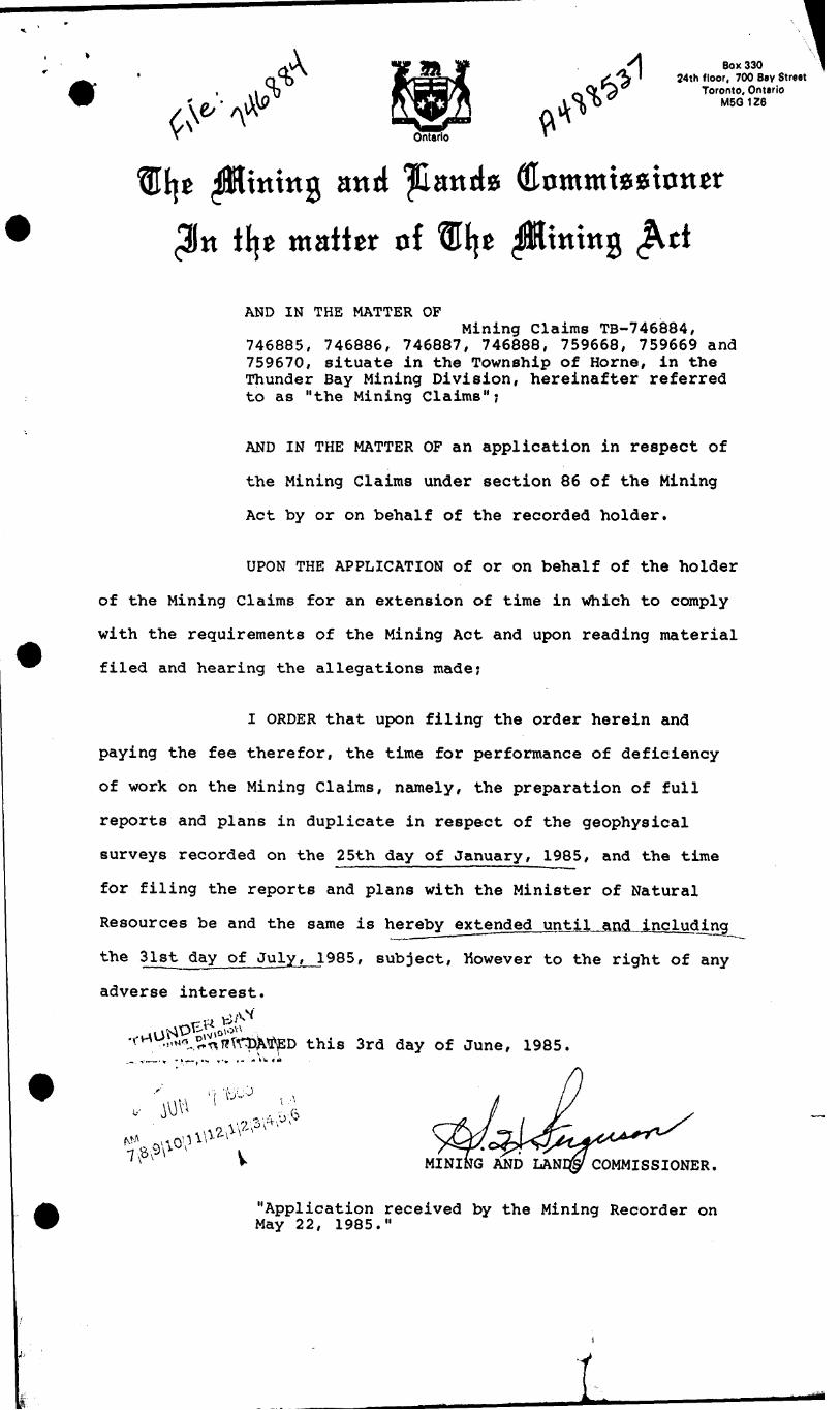
q*Box 330
24th floor, 700 Bay StreetToronto, Ontario
M5G1Z6
itting and ^Catttfo tilt matter of tffljc ^Hitting
AND IN THE MATTER OFMining Claims TB-746884,
746885, 746886, 746887, 746888, 759668, 759669 and 759670, situate in the Township of Horne, in the Thunder Bay Mining Division, hereinafter referred to as "the Mining Claims";
AND IN THE MATTER OF an application in respect of
the Mining Claims under section 86 of the Mining
Act by or on behalf of the recorded holder.
UPON THE APPLICATION of or on behalf of the holder
of the Mining Claims for an extension of time in which to comply
with the requirements of the Mining Act and upon reading material
filed and hearing the allegations made;
I ORDER that upon filing the order herein and
paying the fee therefor, the time for performance of deficiency
of work on the Mining Claims, namely, the preparation of full
reports and plans in duplicate in respect of the geophysical
surveys recorded on the 25th day of January, 1985, and the time
for filing the reports and plans with the Minister of Natural
Resources be and the same is herebyextended untlLajKL including
the 31st day of July ̂ J.985, subject, However to the right of any
adverse interest.
this 3rd day of June, 1985.
'^0
MINING AND LAND COMMISSIONER.
"Application received by the Mining Recorder on May 22, 1985."
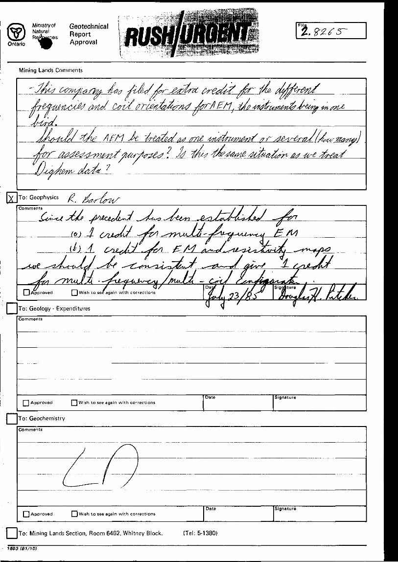
Ministryof Natural
Ontario
Geotechnical [ReportApproval
Fil
Mining Lands Comments
/Wiol Ciw
/ml2 ^
To: Geophysics
DWish to see again with corrections
To: Geology- Expenditures
Comments
l ^| Approved [~~) Wish to see again with correctionsDate Signature
To: Geochemistry
Comments
[ ] Approved [ j Wish to see again with correctionsDate Signature
To: Mining Lands Section, Room 6462, Whitney Block. {Tel: 5-1380)
J593 I8V1D)
Ministry ctNaturalResources
Order of the Minister \
OntarioThe Mining Act
Room 6643. Whitney Block Quegn'i Park , Toronto, Ontario M7A 1W3 416/965-4888
In the matter of mining claims:
SEE ATTACHED SCHEDULE
On consideration of an application from the recorded holder, Jalna Resources Limited S Daniel Calvertunder Section 77 Subsection 22 of The Mining Act, l hereby order that the time for filing reports and plans in support of Airborne Geophysif-al (nprt.rnmagnetic ( Magnetom9Jffijempnt work recorded nn March 13,____1985 be extended until and including " VLr) July 11J9 fi5 .
ISDate
f-Signature of Director, Land Management Branch
Copier Jalna Resources Ltd Calgary, Alberta
Jim Misener Toronto, Ontario
Daniel CalvertRR#.lMurillo, OntarioPOT 2GO
cc: Mining RecorderThunder Bay, Ontario File: 1139
1333 (85/02)
^VY^ ' . u . ./i ^H B ^ i ft.
OJYX. ™
t .JU. R.^-u)., -i jo^Va--)^-J -z^^—Y
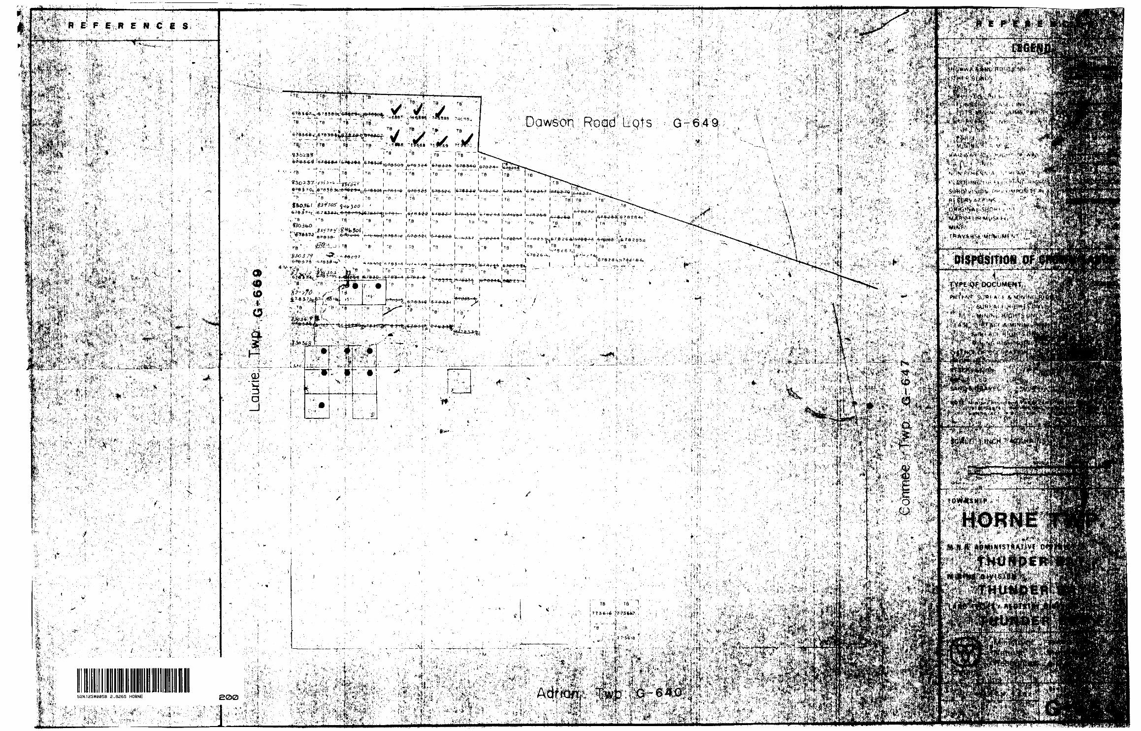
#*V3lV - rH;.;^^;^f; ;;;:^ fev.N; ,-!Sf̂4'ffify:^^*X--* ifc**^ ^''.I'^^^'^^'i^^^ •v-'.'tv :-T t? '- '^'v- 'Mr--' '-f \*3fa f r'- "--'-v v ^-Vi'^r^"L' ^'' v':-;V: ••^•';i -.^'^'^ ^V:-::^i-^\^^^i^^vl^
Bl^P|^;^:|^^^^ •^;*'^T1'i': ^ 5' '"';''"' '"":'f " ' ' "V: itfc" '''"' " "" ''5- ' ' " l *''"'''"'
it-, - .1 ^-wi- J*^^r . :f ^- '' .1 .'l - Lr*OJb^^;'': '"-- ^ ^'^^JV:i^k:^';:/ i. ^ *m#^^^M :f-^L^ M?t
003
*
feS'^pflj^lfiflffSI Ki^S^^g^'^S'fife'M^
-
^-^^-./'te^^;-^^ t ri -;-:VT^* -^^^^Sl L'*' ' "' ''" ' ••-•i .^ is - J*^tiiV. i, ^iV! ' '^"*;' : 1^2'^-i?^ '"' v^'tfS;/ T* ''j, ""'"'' ̂^^' Jli^SigJfciJji - * ' ' ••-•i . is - ti. i, ! ; v'; j, ' ij
k2 /v. i"^4;it v^;f'-: -v*xiv li^'t::t .:. V^'&SS;
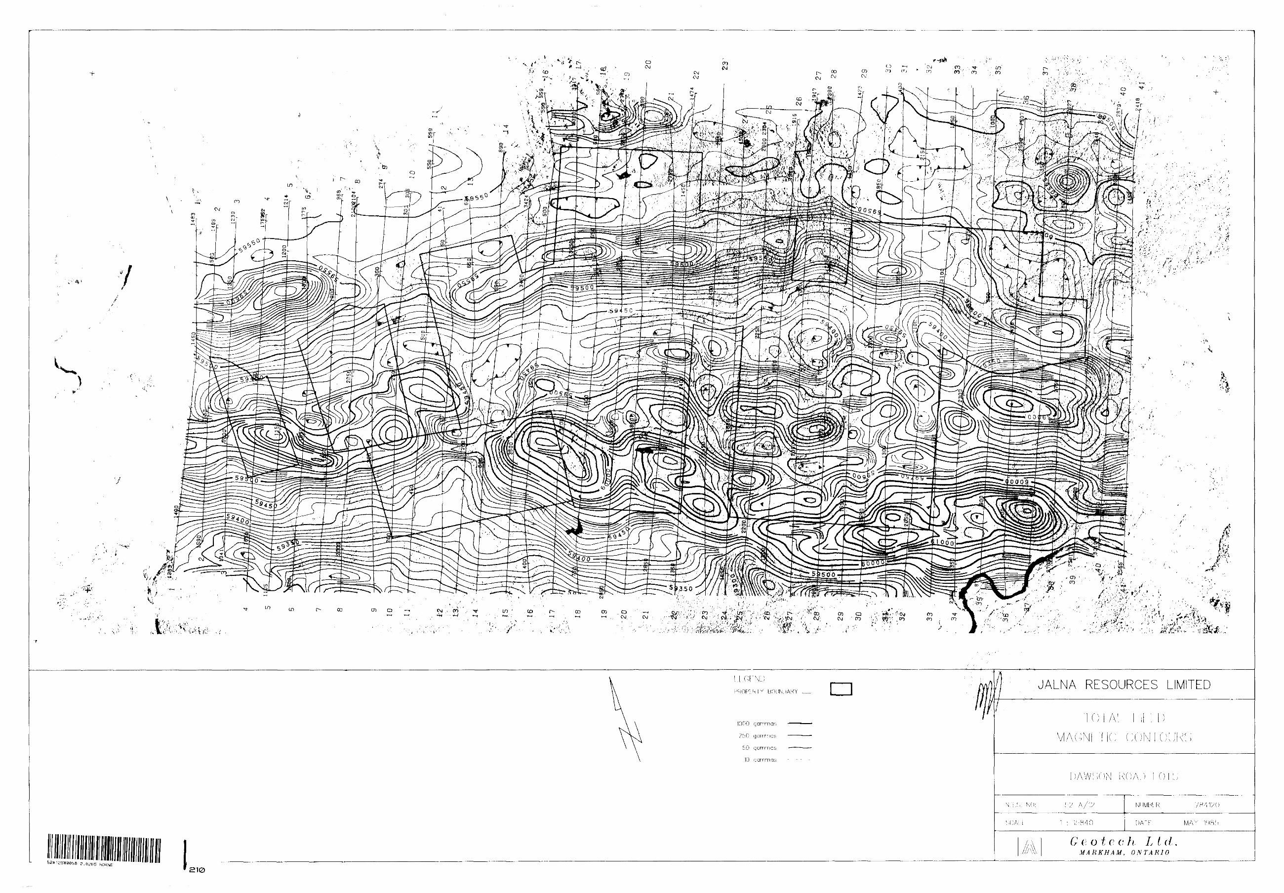
+
}
-f-
52A12SWa058 5 HORNE
JAENA RESOURCES EIMITED
NLIMHtR
e o t c. c h L t dMARKHAM, ONTARIO
210
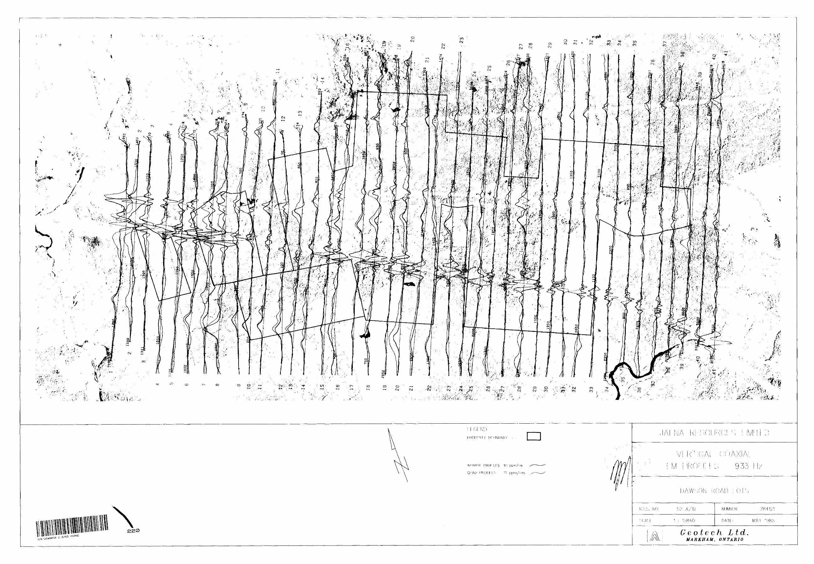
•f
\93?
G e ote eh Ltd.MARKHAM, O NTARIO
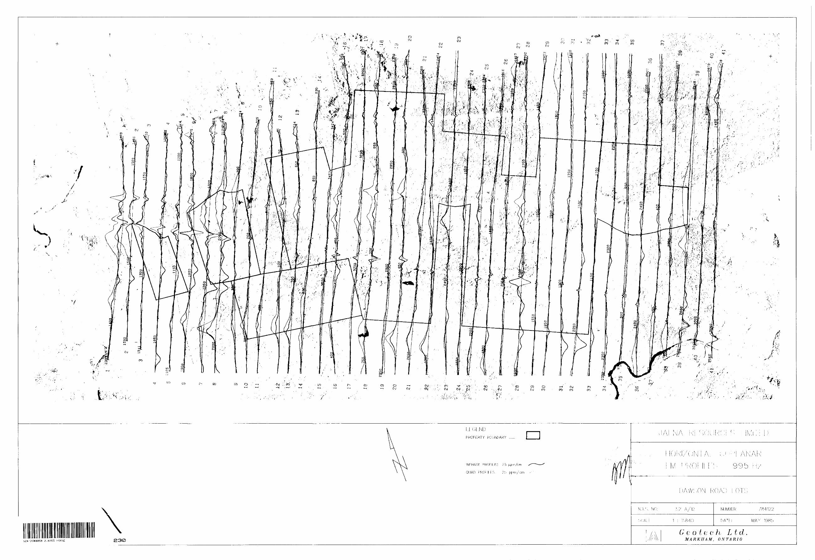
-f m
r Til*''CM P") L -STco ro oo
10 CO
r- ro
LO CO r- co en o OJ r.f^ V 10 to IN CD OJ
tO — i Csj (M
C\J•^ ; oo
J ; -' CXJ
'"''' 'li''''''/*' ',~.-. ' '
^f
•M
r- 1'
p .
'-'w * ,
:,^ .:- , r -' if' '-;.'.
i
CD: Gxj
r-- --, y *\r
- ' j ' ^j8. . -i-- X 1 - ,
"' : ooCsJ
--
en cs;
O en
--* C\Jen m
mCO
m ^•^V ,, ' . - "
^ \ to fo 1 . en
r^07
**
4?tf -'-
lo/
.••,/-^,-
. " v .i , '' J ','
^itfn"/
5EA12SW035B 2.8265 HORNE 230e o ^ e c; /^i L td
MARKHAM, ONTARIO
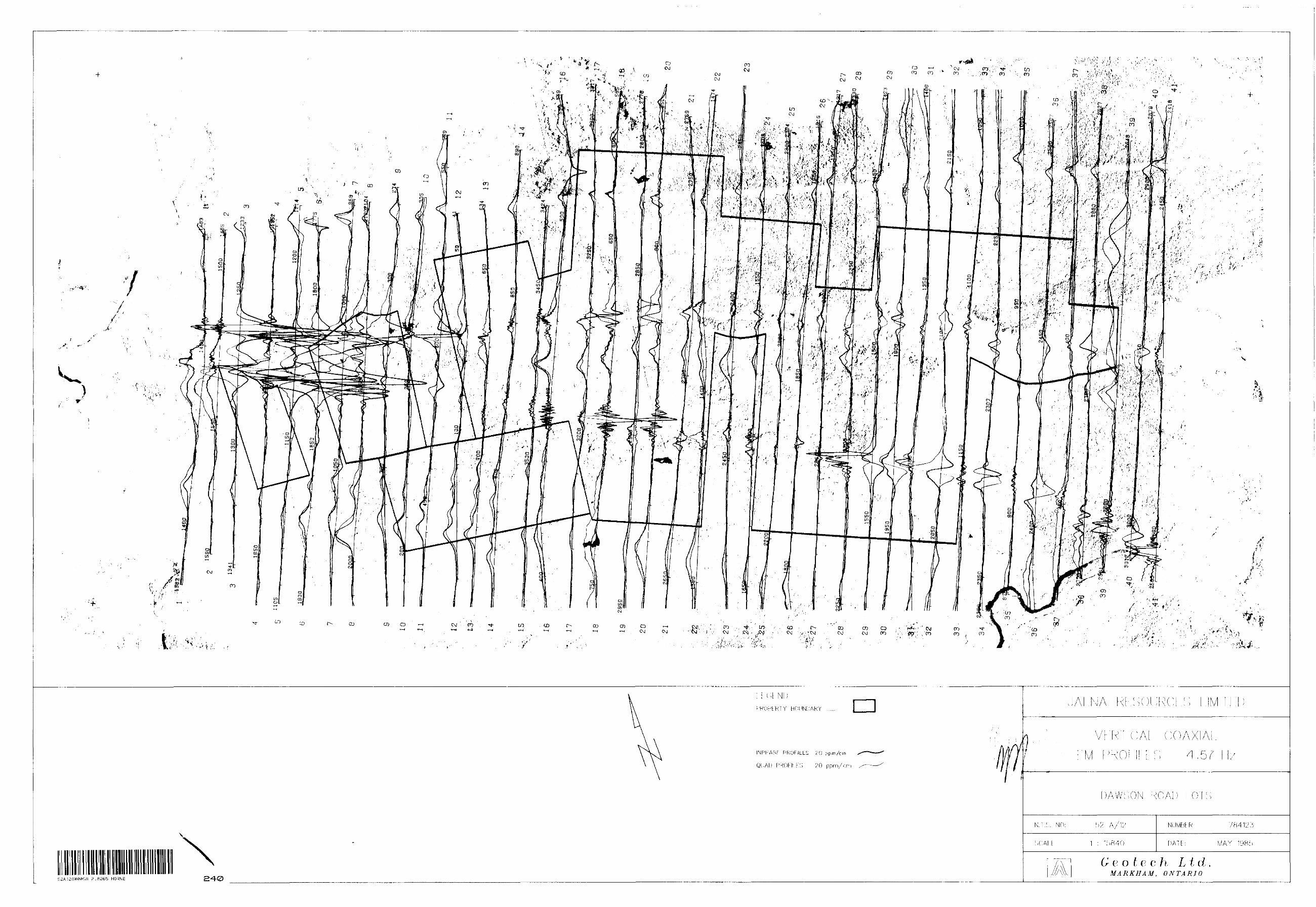
-f-
''•f
l i*
X
.s --
INPHASF PKOFILLS 'SO p pm/cm
QUAD PROFILES 20 ppm/cm
52A'2SW0a58
t^ o f c? c /i L t d .MARKHAM, ONTARIO
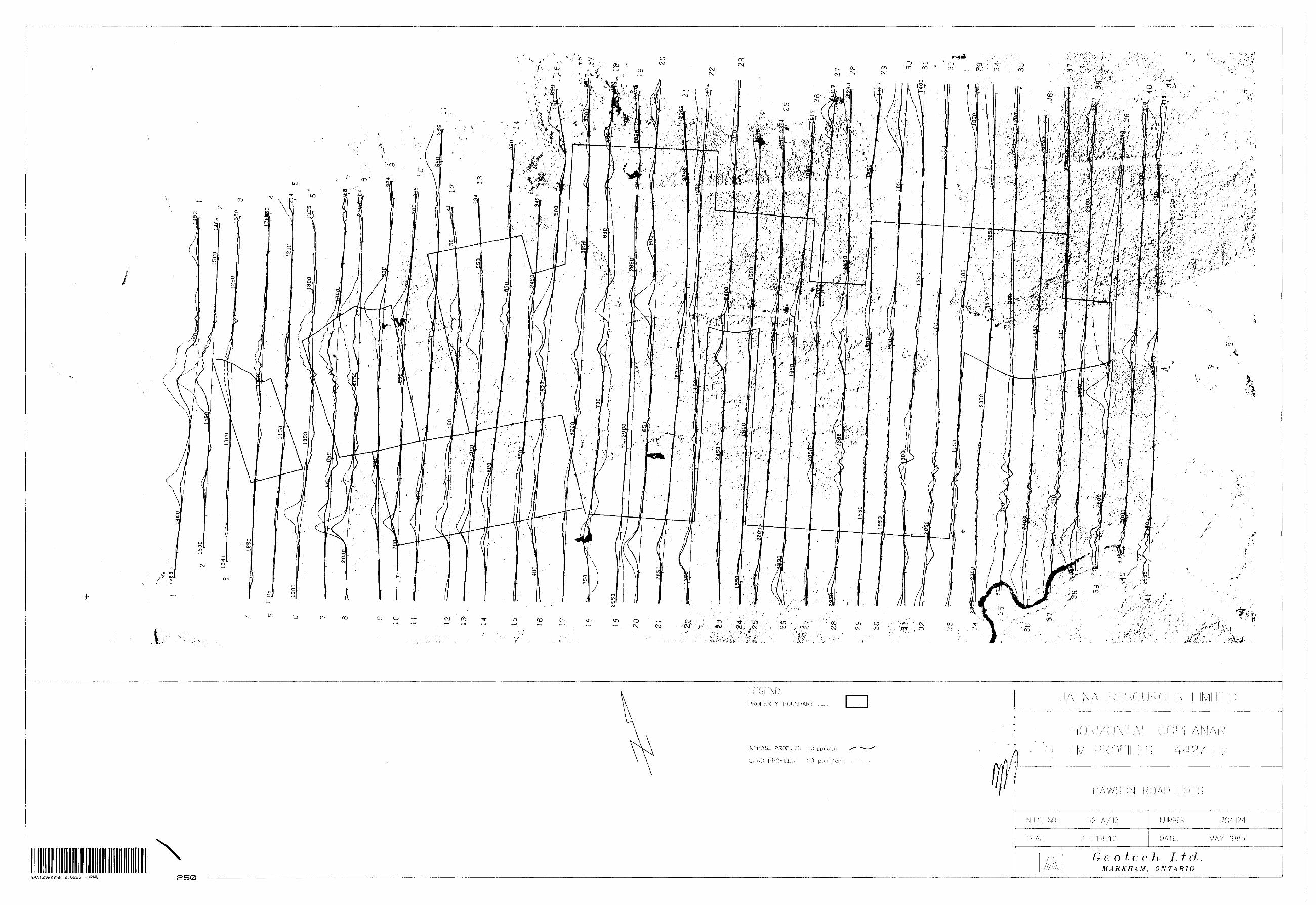
-f-
^'". v v'^r:: .,/;*'-
52A12SW8a58 2.8265 HORNE 250
H.;
Geotcch LtdMARKHAM, ONTARIO
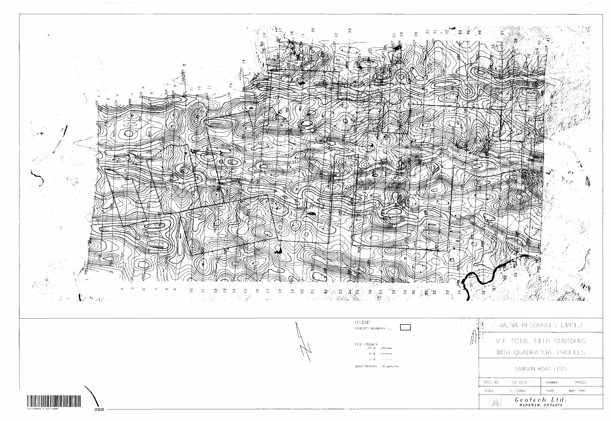
50 7e
10 ?EO c^r
QUAD PROFILES
2.8265 HORNE BG0
W
NUWBE K 84125
G e o t e c h Ltd.MARKHAM, O NTARIO
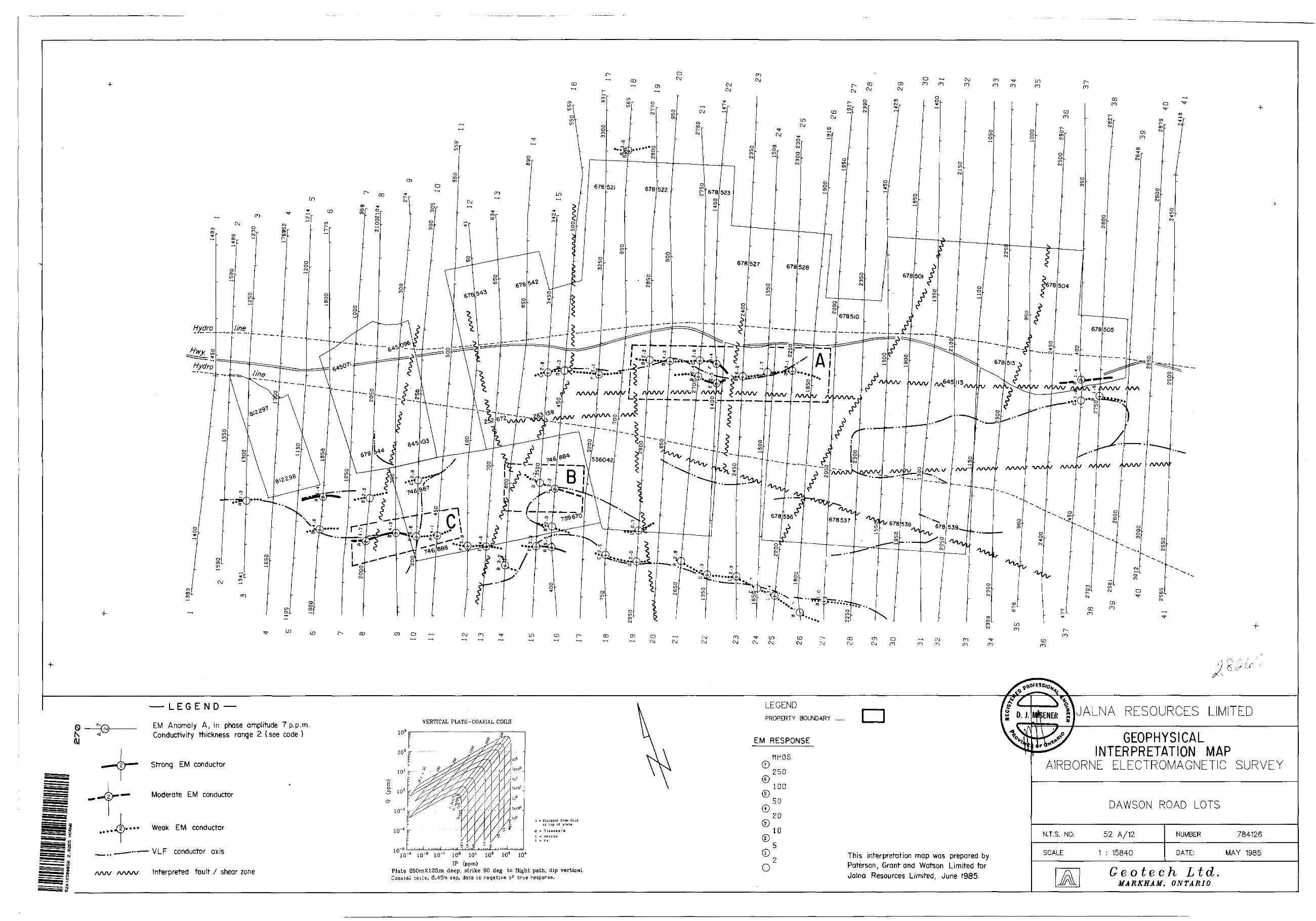
-f CD
ON AJ
— LEG END —
EM Anomaly A, in phase amplitude 7 p.p.m Conductivity thickness range 2 t see code )
Strong EM conductor
Moderate EM conductor
Weak EM conductor
VLF conductor axis
AAA/ AAA/V Interpreted fault 7 shear zone
VERTICAL PLATE-COAXIAL COILS103 g
LEGENDPROPERTY BOUNDARY
EM RESPONSE
MHOS
250
MJALNA RESOURCES LIMITED
GEOPHYSICAL INTERPRETATION MAP
AIRBORNE ELECTROMAGNETIC SURVEY
©ti - distance from bird
to top of plate
O m S i emeus/D
f - Hi
100
50
20
10
ID'3 10'" 10"' l O0 10 l 10 2 103 10*IP Cppm}
Plate 250mX125m deep, strike 90 deg. to flight path, dip vertical. Coaxial coils, 6.45m sep, data i s n egative oF" true response.
©
OThis interpretation map was prepared by Paterson, Grant and Watson Limited for Jalna Resources Limited, June I985.
DAWSON ROAD LOTS
N.T.S. NO: 52 A/12
SCALE : 15840
NUMBER 784126
DATE: MAY 1985
Ge o te eh L td.MARKHAM, O NTARIO