cad/cam (14me 704) - bapatla engineering college · cad/cam (14me 704) scheme of evaluation ......
TRANSCRIPT
Page 1 of 23
IV/IV B. Tech (Regular) DEGREE EXAMINATION November’2017
Mechanical Engineering
CAD/CAM (14ME 704)
Scheme of Evaluation
Max. Marks: 60
--------------------------------------------------------------------------------------------------------------------------------------
1. Answer all the questions. (1x12=12)
(a) What is the importance of a pixel?
Answer: The pixel (a word invented from "picture element") is the basic unit of
programmable color on a computer display or in a computer image. The No. of Pixels in a
square area is called Resolution. If the resolution is more the quality of picture is more and
clear. If resolution is less, the quality of image is less.
(b) List various display devices.
Answer:
1) Cathode Ray Tube (CRT)
2) Raster scan Display
3) Random Scan Display
4) Liquid Crystal Display (LCD)
5) Light Emitting Diode (LED)
(c) What is CSG?
Answer: The Constructive Solid Geometry (CSG) systems allow the user to build the model out of solid graphic primitives, such as rectangular blocks, cubes, spheres, cylinders, and pyramids. In this building-block approach a solid three- dimensional representation of the object is produced. The most common method of structuring the solid model in the graphics data base is to use Boolean operations.
(d) What is rendering?
Answer: Rendering or image synthesis is the automatic process of generating a
photorealistic or non-photorealistic image from a 2D or 3D model (or models in what
collectively could be called a scene file) by means of computer programs. Also, the results of
displaying such a model can be called a rendering. The term "rendering" may be by analogy
with an "artist's rendering" of a scene.
(e) What is Homogeneous coordinate system?
Answer: A homogeneous coordinate system is one in which a 3-dimensional point is represented using four coordinates by adding a dummy coordinate. These are frequently useful in representing the projective operations inherent in computer graphics systems. It has two principal uses:
• It allows the use of 4 × 4 matrices to represent general 3-dimensional transformations • It allows a simplified representation of mathematical functions – the rational form – in which rational polynomial functions can be simply represented.

Page 2 of 23
(f) State different shading methods used.
Answer:
1) Flat shading
2) Smooth shading
(a) Gouraud shading
(b) Phong shading
(c) Fast Phong shading
(g) What are the basic components of NC system?
Answer:
1) Program of instructions or Program
2) Machine control unit (MCU)
3) Processing equipment
(h) What is distributed control?
Answer: Distributed Numerical control (DNC) is a control system in which the central computer is connected to MCUs, which are themselves computers. This permits complete part programs to be sent to the machine tools. Rather than one block at a time. It also permits easier and less costly installation of the overall system, because the individual CNC machines can be put into service and the distributed NC can be added later. Redundant computers improve system reliability compared with the original DNC.
(i) Give the applications of NC. Answer: The operating principle of NC has many applications. There are many industrial operations in which the position of a work head must be controlled relative to a part or product being processed. The applications divide into two categories: (1) Machine tool applications and (2) Non-machine tool applications Machine tool applications are those usually associated with the metalworking industry.
Ex: Turning, drilling, milling and Grinding Non-machine tool applications comprise a diverse group of operations in other industries. It should he noted that the applications are not always identified by the name "numerical control"; this term is used principally in the machine tool industry
Ex: Punch Press, Welding machines, Thermal cutting machines, Tube bending machines
(j) State the applications of Group Technology Answer: (a) Manufacturing applications
o Informal scheduling and routing of similar parts through selected machines
o Virtual machine cells
o Formal machine cells
o Automated process planning
o Modular fixtures
o Parametric programming in NC
(b) Design applications: Design simplification and standardization
(k) What is cellular manufacturing? Answer: Cellular manufacturing is an application of group technology in which dissimilar machines or processes have been aggregated into cells, each of which is dedicated to the production of a part or product family or a limited group of families. Cellular manufacturing is an example of mixed model production.
(l) State the basic components of FMS
1) Work stations
2) Material handling and storage system
3) Computer control system and 4) People
Page 3 of 23
UNIT-I
2. (a) Develop Bresenham’s algorithm to generate a line and discus about its advantages (8M)
Answer: The Bresenham’s algorithm is an incremental scan conversion algorithm. The big
advantage of this algorithm is that, it uses only integer calculations. Moving across the x axis in unit
intervals and at each step choose between two different y coordinates.
This algorithm samples a line by incrementing by one unit either x or y depending on the slope of the
line and then selects the pixel lying at least a distance from the true line path at each sampling
position.
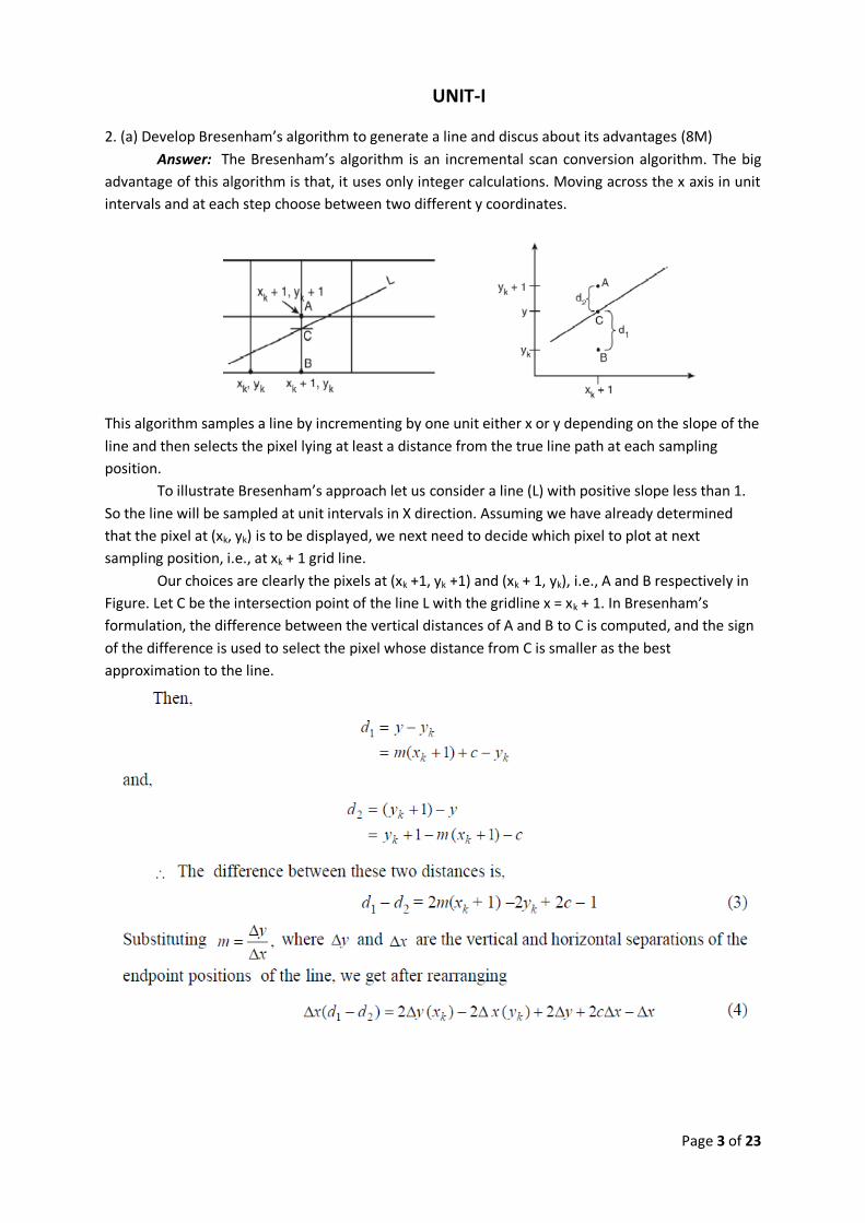
To illustrate Bresenham’s approach let us consider a line (L) with positive slope less than 1.
So the line will be sampled at unit intervals in X direction. Assuming we have already determined
that the pixel at (xk, yk) is to be displayed, we next need to decide which pixel to plot at next
sampling position, i.e., at xk + 1 grid line.
Our choices are clearly the pixels at (xk +1, yk +1) and (xk + 1, yk), i.e., A and B respectively in
Figure. Let C be the intersection point of the line L with the gridline x = xk + 1. In Bresenham’s
formulation, the difference between the vertical distances of A and B to C is computed, and the sign
of the difference is used to select the pixel whose distance from C is smaller as the best
approximation to the line.

Page 4 of 23

Page 5 of 23
Advantages:
1. Simple in calculations
2. Uses integer values thus avoids floating point

Page 6 of 23
(b) Explain the working principle of a CRT display device. (4M)
Answer: The Cathode Ray Tube is today used in computer monitors, TV set s and oscilloscope
tubes. The path of the electrons in the tube filled with a low pressure rare gas can be observed in a
darkened room as a trace of light. Electron beam deflection can be effected by means of either an
electrical or a magnetic field.
Working Principle: The source of the electron beam is the electron gun, which produces a stream of
electrons through thermionic emission at the heated cathode and focuses it into a thin beam by the
control grid
• A strong electric field between cathode and anode accelerates the electrons, before they leave the electron gun through a small hole in the anode. • The electron beam can be deflected by a capacitor or coils in a way which causes it to display an image on the screen. The image may represent electrical waveforms (oscilloscope), pictures (television, computer monitor), echoes of aircraft detected by radar etc. •When electrons strike the fluorescent screen, light is emitted. • The whole configuration is placed in a vacuum tube to avoid collisions between electrons and gas molecules of the air, which would attenuate the beam.
(OR)
3. (a) Describe DDA algorithm for the generation of line. Write its advantages and limitations. (6M)
Answer: The digital differential analyzer (DDA) algorithm is an incremental scan-conversion method. Such an approach is characterized by performing calculations at each step using results from the preceding step.

Page 7 of 23
Advantages of DDA: (1) It is simplest algorithm and does not require special skill for implementation. (2) It is a faster method for calculating pixel values instead of using the equation directly.
Limitations of DDA: (1) The rounding operation & floating point arithmetic are time consuming procedures. (2) The accumulation of round-off error in successive addition of floating point increment can
cause the calculated pixel position to drift away from the true line path for long line segment.

Page 8 of 23
(b) Find the position in Homogeneous coordinates for the initial point P (2, 1, 3) which is rotated about 600 in counter clockwise direction. (6M)

Page 9 of 23
UNIT-II
4. (a) Develop parametric equation to generate B-Spline curve and discus its advantages. (6M)
Answer:

Page 10 of 23

Page 11 of 23

Page 12 of 23
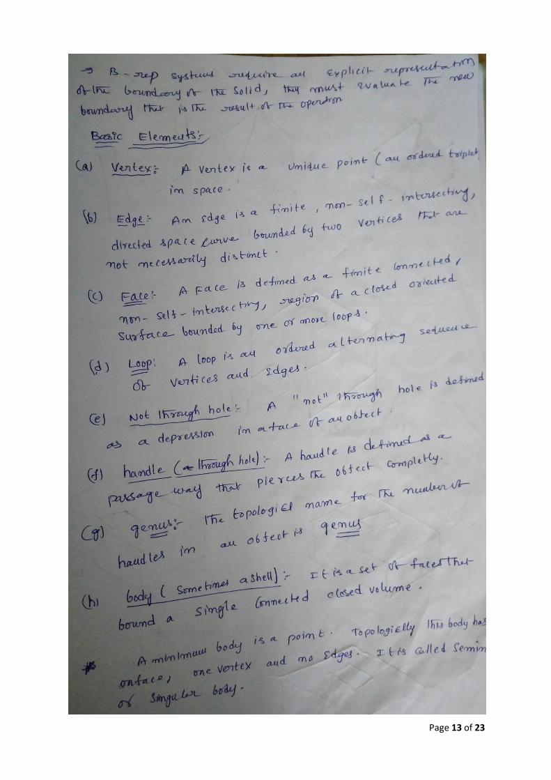
(b) Explain about boundary representation in solid modeling. (6M)
Answer:
Page 13 of 23

Page 14 of 23
(OR)
5. (a) Explain the hidden line removal technique in related to visual realism (6M)
Answer: Hidden line removal (HLR) is the method of computing which edges are not hidden by the faces of parts for a specified view and the display of parts in the projection of a model into a 2D plane. Hidden line removal is utilized by a CAD to display the visual lines. It is considered that information openly exists to define a 2D wireframe model as well as the 3D topological information. Typically, the best algorithm is required for viewing this information from an available part representation. 3D parts are simply manufactured and frequently happen in a CAD design of such a part. In addition, the degrees of freedom are adequate to show the majority of models and are not overwhelming in the number of constraints to be forced. Also, almost all the surface-surface intersections and shadow computations can be calculated analytically which results in significant savings in the number of computations over numerical methods

Page 15 of 23
Priority algorithm: Priority algorithm is basis on organization all the polygons in the view according to the biggest Z-coordinate value of each. If a face intersects more than one face, other visibility tests besides the Z- depth required to solve any issue. This step comprises purposes of wrapper. Imagines that objects are modeled with lines and lines are generated where surfaces join. If only the visible surfaces are created then the invisible lines are automatically removed.
ABCD, ADFG, DCEF are given higher priority-1. Hence, all lines in this faces are visible, that is, AB, BC, CD, DA, AD, DF, FG, AG, DC, CE, EF and DF are visible. AGHB, EFGH, BCEH are given lower priority-2. Hence, all lines in this faces other than priority-1 are invisible, that is BH, EH and GH. These lines must be eliminated.
(b) What is shading? Develop the algorithm for shading in solid modeling. (6M) Answer: Shading refers to depicting depth perception in 3D models or illustrations by varying levels of darkness. In the field of computer graphics, a shader is a special type of computer program that was originally used to do shading (the production of appropriate levels of light, darkness, and color within an image) but which now perform a variety of specialized functions in various fields of computer graphics special effects or do video post-processing unrelated to shading, and even functions unrelated to graphics at all.
Shaders calculate rendering effects on graphics hardware with a high degree of flexibility. Most shaders are coded for a graphics processing unit (GPU), though this is not a strict requirement. Shading languages are usually used to program the programmable GPU rendering pipeline, which has mostly superseded the fixed-function pipeline that allowed only common geometry transformation and pixel-shading functions; with shaders, customized effects can be used. The position, hue, saturation, brightness, and contrast of all pixels, vertices, or textures used to construct a final image can be altered on the fly, using algorithms defined in the shader, and can be modified by external variables or textures introduced by the program calling the shader.
The following shading models are popularly used.
1. Flat shading
2. Smooth shading
(a) Gouraud shading
(b) Phong shading
(c) Fast Phong shading
UNIT-III
6. (a) What are the features of CNC? Explain in detail. (6M)
Page 16 of 23
Answer: Computer NC systems include additional features beyond what is feasible with conventional hard-wired NC. These features, many of which are standard on most CNC MCUs where as others are optional, include the following:
1) Storage of more than one part program: With improvements in computer storage technology. Newer CNC controllers have sufficient capacity to store multiple programs. Controller manufacturers generally offer one or more memory expansions as options to the MCU.
2) Various forms of program input. Whereas conventional (hard-wired) MCUs are limited to punched tape as the input medium for entering part programs. CNC controllers generally possess multiple data entry capabilities, such as punched tape (if the machine shop still uses punched tape), magnetic tape. Floppy diskette.
3) Program edit at the machine tool. CNC permits a part program to be edited while it resides in the MCU computer memory. Hence, the process of testing and correcting a program can be done entirely at the machine site, rather than returning to the programming office to correct the tape. In addition to part program corrections, Editing also permits optimizing cutting conditions in the machining cycle. After correcting and optimizing the program. The revised version can be stored on punched tape or other media for future use.
4) Fixed cycles and programming subroutines. The increased memory capacity and the ability to program the control computer provide the opportunity to store frequently used machining cycles as macros that can be called by the part program. Instead of writing the full instructions for the particular cycle into every program, a call statement is included in the part program to indicate that the macro cycle should be executed. These cycles often require that certain parameters be defined; for example. A bolt hole circle, in which the diameter of the bolt circle, the spacing of the bolt holes, and other parameters must be specified.
5) Interpolation. Some of the interpolation schemes are normally executed only on a CNC system because of the computational requirements. Linear and circular interpolation arc sometimes hard-wired into the control unit, but helical, parabolic and cubic interpolations are usually executed in a stored program algorithm.
6) Positioning features for setup. Setting up the machine tool for a given work part involves installing and aligning a fixture on the machine tool table. This must be accomplished so that the machine axes are established with respect to the work part; the alignment task can be facilitated using certain features made possible by software options in a CNC system. Position set is one of these features. With position set, the operator is not required to locate the fixture on the machine table with extreme accuracy. Instead, the machine tool axes are referenced to the location of the fixture by using a target point or set of target points on the work or fixture.
7) Cutter length and size compensation. In older style controls, cutter dimensions had to be set very precisely to agree with the tool path defined in the part program. Alternative methods for ensuring accurate tool path definition have been incorporated into CNC controls. One method involves manually entering the actual tool dimensions into the MCU. These actual dimensions may differ from those originally programmed Compensations are then automatically made in the computed tool path. Another method involves use of a tool length sensor built into the machine. In this technique, the cutter is mounted in the spindle and the sensor measures its length. This measured value is then used to correct the programmed tool path.
8) Acceleration and deceleration calculations: This feature is applicable when the cutter moves at high feed rates. It is designed to avoid tool marks on the work surface that would be generated due to machine tool dynamics when the cutter path changes abruptly. Instead, the feed rate is smoothly decelerated in anticipation of a tool path change and then accelerated back up to the programmed feed rate after the direction change.
9) Communications interface. With the trend toward interfacing and networking in plants today, most modem CNC con/rollers are equipped with a standard RS-232 or other

Page 17 of 23
communications interface to allow the machine to be linked to other computers and computer-driven devices. This is useful for various applications, such as: (1) downloading part programs from a central data file as in distributed NC; (2) collecting operational data such as work piece counts, cycle times, and machine utilization; and (3) interfacing with peripheral equipment, such as robots that load and unload parts.
10) Diagnostics. Many modern CNC systems possess an on-line diagnostics capability that monitors certain aspects of the machine tool to detect malfunctions or signs of impending malfunctions or to diagnose system breakdowns.
(b) Explain principles of DNC. (6M)
Answer: Direct Numerical Control: The first attempt to use a digital computer to drive the NC machine tool was DNC. As initially implemented DNC involved the control or a number of machine tools by a single (mainframe) computer through direct connection and in real time. Instead of using a punched tape reader to enter the part program into the MCU, the program was transmitted to the MCU directly from the computer, one block of instructions at a time. This mode of operation was referred to by the name behind the tape reader (BTR).
The DNC computer provided instruction blocks to the machine tool on demand; when a machine needed control commands, they were communicated to it immediately. As each block was executed by the machine, the next block was transmitted. As far as the machine tool was concerned, the operation was no different from that of a conventional NC controller. In theory, DNC relieved the NC system of its least reliable components: the punched tape and tape reader.
The general configuration of a DNC system is depicted in Figure. The system consisted of four components: (1) central computer, (2) bulk memory at the central computer site, (3) set of controlled machines, and (4) telecommunications lines to connect the machines to the central computer. In operation, the computer caned the required part program from bulk memory and sent it (one block at a time) to the designated machine tool. This procedure was replicated for all machine toots under direct control of the computer.
Distributed Numerical Control: The configuration of the DNC is very similar to that of Direct numerical control except that the central computer is connected to MCUs, which are themselves computers. This permits complete part programs to be sent to the machine tools rather than one block at a time. It also permits easier and less costly installation of the overall system, because the individual CNC machines can be put into service and the distributed NC can be added later.
Redundant computers improve system reliability compared with the original DNC. The new DNC permits two-way communication of data between the shop floor and the central computer which was one of the important features included in the old DNC. However, improvements in data collection devices as well as advances in computer and communications technologies have expanded the range and flexibility of the information that can be gathered and disseminated. Distributed NC systems can take on a variety of physical configurations, depending on the number of machine tools included, job complexity, security requirements, and equipment availability and preferences. There are several ways to configure a DNC system.

Page 18 of 23
(a) Switching network (b) LAN
(OR)
7. (a) Explain any four different ways of representing circles and planes in APT geometry. (6M)
Answer: CIRCLE: Circle (geometry type). Used to define a circle in the x-y plane. Methods of definition include: 1. Using the coordinates of its center and its radius (see Figure):
C1 = CIRCLE/CENTER, 100, 50, 0, RADIUS, 32 2. Using the point identifying its center and its radius (see Figure):
C1 = CIRCLE/CENTER, PI, RADIUS, 32 3. Using the point identifying its center and a line to which it is tangent (see Figure):
C1 = CIRCLEICENTER, P1, TANTO, L1
PLANE: Plane (geometry type). Used to define a plane. Methods of definition include: 1. Using three points that do not lie on the same straight line:
PL1= PLANEIPI, P2, P3 2. Using a point and parallelism to another plane:
PL2 = PLANEIP4, PARLEL, PL1 3. Using two points and perpendicularity to another plane:
P13 = PLANE/P5, PO, PFRPTO, PL1
(b) Describe point to point and contouring motion statements. (6M) Answer: Point-to-point motions, there are only two commands: GOTO and GODLTA. The
GOTO statement instructs the tool to go to a particular point location specified in the descriptive data. Two examples are:
GOTO/P2 GOTO/25.0, 40, 0, 0

Page 19 of 23
In the first command, P2 is the destination of the tool point. In the second command, the tool has been instructed to go to the location whose coordinates are x = 25.0, Y = 40.0, and z = 0.
The GODLTA command specifies an incremental move for the tool. To illustrate, the following statement instructs the tool to move from its present position by a distance of 50.0 mm in the x-direction, 120.0 mm in the y-direction, and 40 rum in the z-direction
GODLTA/50.0, 120.0, 40.0 The GODLTA statement is useful in drilling and related machining operations. The tool can be directed to go to a given hole location; then the GODLTA command can be used to drill the hole, as in the following sequence:
GOTO/P2 GODLTA/0, 0, -50.0 GODLTA/O, 0, 50.0
Contouring motion commands are more complicated than PTP commands because the tool's position must be continuously controlled throughout the move. To exercise this control, the tool is directed along two intersecting surfaces until it reaches a third surface, as shown in Figure. These three surfaces have specific names in APT; they are: 1. Drive surface. This is the surface that guides the side of the cutler. It is pictured as plane in our figure. 2. Part surface. This is the surface, again pictured as a plane, on which the bottom or nose of the tool is guided. 3. Check surface. This is the surface that stops the forward motion of the tool in the execution of the current command. One might say that this surface "checks" the advance of the tool.
An APT contouring motion command causes the cutter to proceed along a trajectory defined by the drive surface and part surface; when the tool reaches the check surface it stops according to one of the modifier words TO, ON, PAST, or TANTO. In writing a motion statement, the part programmer must keep in mind the direction from which the tool is coming in the preceding motion command. The programmer must pretend to be riding on top of the tool, as if driving a car.
UNIT-IV
8. (a) Explain OPITZ coding system. (7M)
Answer: This system was developed by H. OPITZ of the University of Aachen in Germany. It represents one of the pioneering efforts in group technology and is probably the best known, if not the most frequently used, of the parts classification and coding systems. It is intended for machined parts. The OPITZ coding scheme uses the following digit sequence:
12345 6789 ABCD The basic code consists of nine digits, which can be extended by adding four more digits. The first nine are intended to convey both design and manufacturing data. The interpretation of the first nine

Page 20 of 23
digits is defined in Figure. The first five digits, 12345, are called the form code. It describes the primary design attributes of the part, such as external shape (e.g., rotational vs. rectangular) and machined features (e.g., holes, threads, gear teeth, etc.) The next four digits, 6789, constitute the supplementary code, which indicates some of the attributes that would be of use in manufacturing (e.g., dimensions, work material, starting shape, and accuracy). The extra four digits, ABCD, are referred to as the secondary code and are intended to identify the production operation type and sequence. The secondary code can be designed by the user firm to serve its own particular needs.
(b) Discus about functions of computer control system in FMS. (5M)
Answer: Functions performed by the FMS computer control system can be grouped into the following categories: 1. Workstation control. In a fully automated FMS, the individual processing or assembly stations generally operate under some form of computer control. For a machining system, CNC is used to control the individual machine tools. 2. Distribution of control instructions to workstations. Some form of central intelligence is also required to coordinate the processing at individual stations. In a machining FMS, part programs must be downloaded to machines, and DNC is used for this purpose, The DNC system stores the programs, allows submission of new programs and editing of existing programs as needed, and performs other DNC functions 3. Production control. The part mix and rate at which the various parts are launched into the system must be managed. Input data required for production control includes desired daily production rates per part. Numbers of raw work parts available, and number of applicable pallets.' The production control function is accomplished by routing an applicable pallet 10 the load/unload area and providing instructions to the operator for loading the desired work part. 4. Traffic control. This refers to the management of the primary material handling system that moves work parts between stations. Traffic control is accomplished by actuating switches at branches and merging points. Stopping parts at machine tool transfer locations, and moving pallets to load/unload stations. 5. Shuttle control. This control function is concerned with the operation and control of the secondary handling system at each workstation. Each shuttle must be coordinated with the primary handling system and synchronized with the operation of the machine tool it serves.

Page 21 of 23
6. Work piece monitoring. The computer must monitor the status of each cart and/or pallet in the primary and secondary handling systems as well as the status of each of the various work piece types. 7. Tool control: In a machining system, cutting tools are required. Tool control is concerned with managing two aspects of the cutting tools:
o Tool location. This involves keeping track of the cutting tools at each workstation, If one or mere tools required to process a particular work piece is not present at the station that is specified in the part's routing, the tool control subsystem takes one or both of the following actions: (a) determines whether an alternative workstation that has the required tool is available and/or (b) notifies the operator responsible for tooling in the system that the tool storage unit at the station must be loaded with the required cutter(s).
o Tool life monitoring: In this aspect of tool control, a tool life is specified to the computer for each cutting tool in the FMS.A record of the machining time usage is maintained for each of the tools, and when the cumulative machining time reaches the specified life of the tool, the operator is notified that a tool replacement is needed.
8. Performance monitoring and reporting: The computer control system is programmed to collect data on the operation and performance of the FMS. This data is periodically summarized, and reports are prepared for management on system performance. 9. Diagnostics: This function is available to a greater or lesser degree on many manufacturing systems to indicate the probable source of the problem when a malfunction occurs. It can also be used to plan preventive maintenance in the system and to identify Impending failures. The purpose of the diagnostics function is to reduce breakdowns and downtime and increase availability of the system.
(OR)
9. (a) Explain retrieval type CAPP system (6M)
Answer: A retrieval CAPP system, also called a variant CAPP system, is based on the principles of group technology (GT) and parts classification and coding .In this type of CAPP, a standard process plan (route sheet) is stored in computer files for each part code number. The standard route sheets are based on current part routings in use in the factory or on an ideal process plan that has been prepared for each family. It should be noted that the development of the data base of these process plans requires substantial effort. Before the system can be used for process planning, a significant amount of information must be compiled and entered into the CAPP data files. This is called as the "preparatory phase:' It consists of the following steps: (1) selecting an appropriate classification and coding scheme for the company, (2) forming part families for the parts produced by the company; and (3) preparing standard process plans for the part families. It should be mentioned that steps (2) and (3) continue as new parts are designed and added to the company's design data base.

Page 22 of 23
(b) Differentiate CAD/CAM and CIM (6M)
Answer: CAD/CAM is concerned with the engineering functions in both design and manufacturing. Product design, engineering analysis, and documentation of the design (e.g. drafting) represent engineering activities in design. Process planning, NC part programming, and other activities associated with CAM represent engineering activities in manufacturing. The CAD/CAM systems developed during the 1970s and early 1980s were designed primarily to address these types of engineering problems. In addition, CAM has evolved to include many other functions in manufacturing, such as material requirements planning, production scheduling, computer production monitoring, and computer process control. It should also be noted that CAD/CAM denotes an integration of design and manufacturing activities by means of computer systems. The method of manufacturing a product is a direct function of its design. Computer integrated manufacturing (CIM) includes all of the engineering functions of CAD/CAM, but it also includes the firm's business functions that are related to manufacturing. The ideal CIM system applies computer and communications technology to all of the operational functions and information processing functions in manufacturing from order receipt, through design and production, to product shipment. The scope of CIM, compared with the more limited scope of CAD/CAM is shown in the diagram.

Page 23 of 23
Prepared by:
Rajasekharababu. K,
Asst. Professor,
Dept. of Mechanical Engineering
Cell: +91 8106199932
Bapatla,
17. Nov. 2017