catalogue - cebeco.com.aucatalogue explosion-protected products cooper crouse-hinds australia valid...
TRANSCRIPT

CatalogueExplosion-Protected ProductsCooper Crouse-Hinds Australia
Valid from June 2010 ©2010 Cooper Industries, Plc.
Your Authorized Cooper Crouse-Hinds Distributor is:
Cooper Industries, Ltd.600 Travis, Ste. 5800Houston, TX 77002-1001P:713-209-8400www.cooperindustries.com
www.crouse-hinds.comCooper Crouse-Hinds is a registered trademarkof Cooper Industries, Plc.©2010 Cooper Industries, Plc.
Cooper Crouse-Hinds (Global HQ)Wolf & Seventh North StreetsSyracuse, NY 13221(866) 764-5454FAX: (315) [email protected]
Cooper Crouse-HindsMTL InstrumentsGreat Marlings, ButterfieldLuton UK LU2 8DL+44 (0)1582 723633FAX: +44 (0)1582 [email protected]
Cooper Crouse-Hinds Pauluhn1616 N Main StPearland, TX 77581(281) 485-4311FAX: (281) [email protected]
Cooper Crouse-HindsAirport Lighting1200 Kennedy RoadWindsor, CT 06095(860) 683-4354FAX: (860) [email protected]
Cooper Crouse-Hinds GmbHNeuer Weg-Nord 49Eberbach, Germany D-6941249 (0) 6271 806-500FAX: 49 (0) 6271 [email protected]
For more information:If further assistance is required, please contact an authorized Cooper Crouse-Hinds Distributor,Sales Office, or Customer Service Department.
Cooper Crouse-Hinds Regional Offices
Australia:61-2-8787-2777FAX: [email protected]
China:86-21-2899-3600FAX: [email protected]
Canada:800-265-0502FAX: (800) 263-9504FAX Orders only: (866) 653-0645
Mexico/Latin America/Caribbean:52-555-804-4000FAX: [email protected]
Saudi Arabia:966 3 812 2236FAX: 966 3 812 1291
India:91-124-4683888FAX: [email protected]
Brazil:+55 15 3238 3970FAX: +55 15 3238 [email protected]
Colombia:+ (57.1) 670 0315FAX: + (57.1) 670 [email protected]
Canada (Pauluhn):[email protected]
Middle East (Dubai):971 4 4272500FAX: 971 4 4298521
Korea:82 2 538 3425FAX: 82 2 538 [email protected]
Singapore:65-6297-4849FAX: [email protected]
UK:+44 247-630-89 30FAX: +44 247-630-10 [email protected]
Australia C
atalog
ue

Company Profile
June, 2010 Copyright© Cooper Industries
By integrating a comprehensive line of electrical andinstrumentation products with expert support,industry insights, and local availability,Cooper Crouse-Hinds enhances safety andproductivity in the most demanding industrial,harsh, and hazardous environments worldwide. Thisphilosophy is at the core of every product wedevelop and every solution we engineer.
For more than a century, companies haverelied on Cooper Crouse-Hinds for solutionsthey can trust to grow their business.
Cooper Crouse-Hinds manufactures over100,000 products for NEC, IEC and ABSapplications across the globe, including• Conduit and cable fittings• Enclosures• Motor Controls and Electrical Apparatus• Industrial and Marine Lighting• Plugs & Receptacles• Signals and Alarms• Wireless and Solar Power• Commercial Fittings and Outlet Boxes• Electronic components and protection
equipment for process control
The more demanding theenvironment, the likely it is that youwill find our products in operation.

Company Profile
Copyright© Cooper Industries June, 2010
Catalog Layout
Section 1 Application ProtectionTechniques
Section 2 Conduit and Cable Fittings
Section 3 Junction Boxes
Section 4 Industrial Control
Section 5 Lighting
Section 6 Plugs & Receptacles
Welcome to the enhanced and expandedCooper Crouse-Hinds catalog. This catalog includesproducts from the following 5 major product lines.
As the electrical industry’s globalleader for hazardous environments, we’reconstantly pushing forward and looking ahead,advancing electrical and instrumentationproducts in new and innovative ways.
We do this with a singular goal in mind —Enhancing Safety and Productivitythoughout your operation. It’s all fueled by afierce dedication to providing global solutions,worldwide reliability and intelligence andexpertise.
Every new product or initiative must live up tothese uncompromising standards.
At Cooper Crouse-Hinds,innovation is in our DNA.
The product information published in our catalogs and literaturehas been compiled with care and is sufficiently accurate for mostpurposes. It is subject to change without notice. Occasionally, itmay be necessary to modify the materials, finishes, or othercomponents of the product. These changes will in no wayreduce the performance or function for which the product isintended.
All statements, technical information and recommendationscontained herein are based on information we believe to bereliable. The accuracy or completeness thereof are notguaranteed. In accordance with Cooper Crouse-Hinds’ Termsand Conditions of Sale, and since conditions of use are outsideour control, the purchaser should determine the suitability of theproduct for his/her intended use and assumes all risk and liabilitywhatsoever in connection therewith.
All sales of Cooper Crouse-Hinds products are specificallysubject to the Terms and Conditions of Sale as shown on CooperCrouse-Hinds distributor or trade price sheets.
June, 2010 Copyright© Cooper Industries
A table of contents appears in the front of each section listingthe products contained in the section by both series prefix(e.g. DSEA) and general product type.
PRODUCT INFORMATION:
On the individual catalogue pages information is given for eachproduct family regarding application, features, compliances andcertification, options available and ordering information.
To help make the catalogue easier to use, a common locationof the materials appearing on each page is used whereverpossible.
MEASUREMENTS:
All units of measurements shown in this catalogue are in metricunits of mm and kg (except where otherwise indicated).
The product information published in our catalogues and litera-ture is not guaranteed. It has been compiled with care and issufficiently accurate for most purposes. It is subject to changewithout notice. Occasionally, it may be necessary to modify thematerials, finishes, or other components of the products. Thesechanges in no way will reduce the performance or function forwhich the product is intended.
All statements, technical information and recommendations con-tained herein are based on information and tests we believe tobe reliable. The accuracy or completeness thereof is not guar-anteed. In accordance with Cooper Electrical Terms and Condi-tions of Sale, and since conditions of use are outside ourcontrol, the purchaser should determine the suitability of theproduct for his intended use and the purchaser assumes all riskand liability whatsoever in connection therein.
1 Application Protection Techniques
2 Fittings
3 Enclosures
4 Industrial Control
5 Hazardous Area Lighting
6 Hazardous Area Plugs & Receptacles
MAJOR SECTIONS:
Our Catalogue is divided into six major product sections:
About Our Catalogue
Section 1 Index
Copyright© Cooper Industries June, 2010
1-1
Explosion Protection
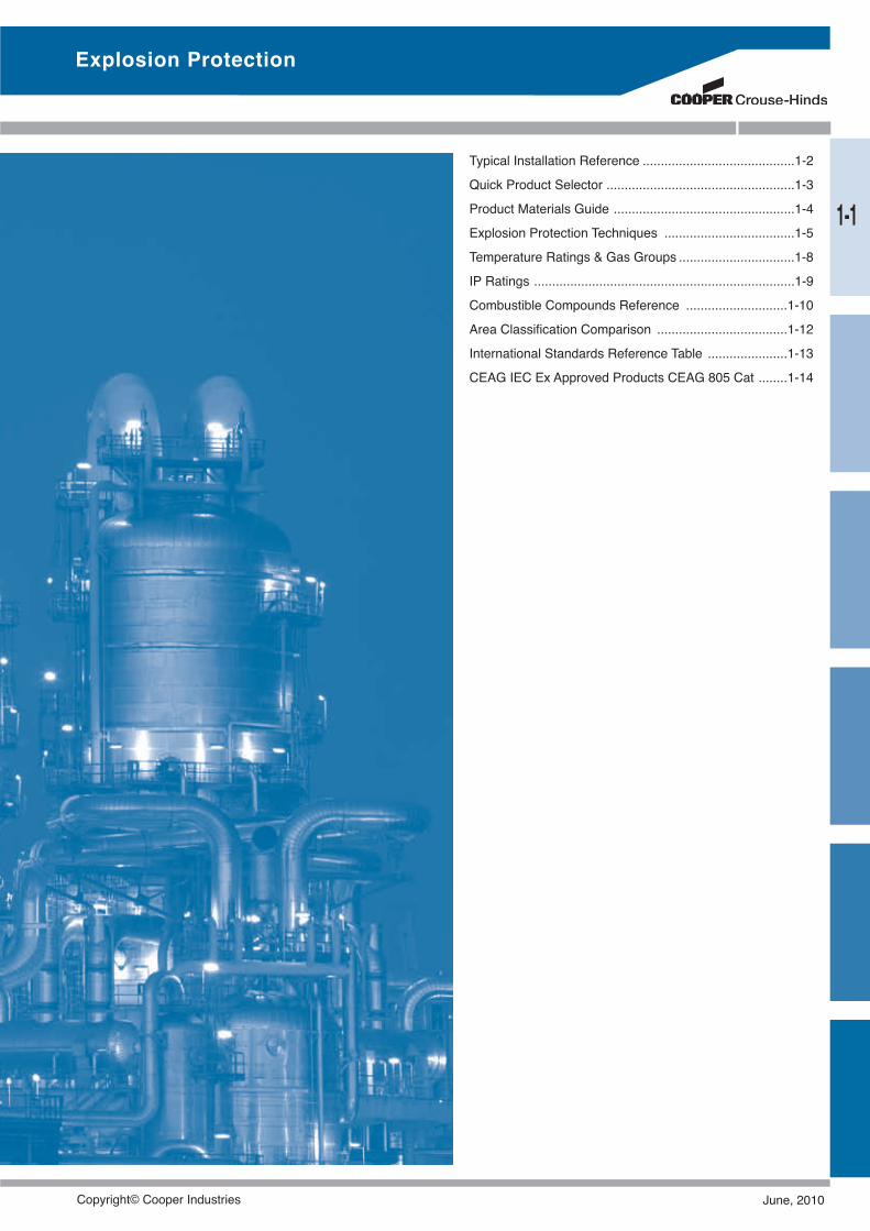
Typical Installation Reference ..........................................1-2Quick Product Selector ....................................................1-3Product Materials Guide ..................................................1-4Explosion Protection Techniques ....................................1-5Temperature Ratings & Gas Groups ................................1-8IP Ratings ........................................................................1-9Combustible Compounds Reference ............................1-10Area Classification Comparison ....................................1-12International Standards Reference Table ......................1-13CEAG IEC Ex Approved Products CEAG 805 Cat ........1-14
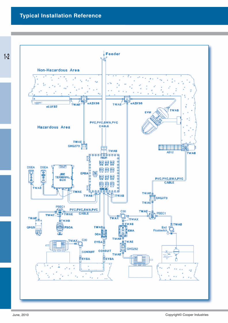
Typical Installation Reference
1-2
June, 2010 Copyright© Cooper Industries
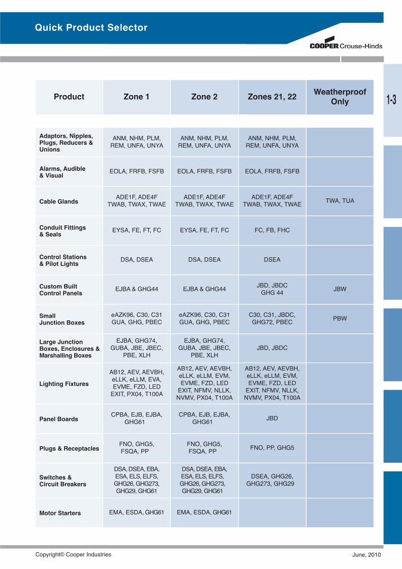
Quick Product Selector
Product Zone 1 Zone 2 Zones 21, 22 WeatherproofOnly
Adaptors, Nipples,Plugs, Reducers &Unions
ANM, NHM, PLM,REM, UNFA, UNYA
ANM, NHM, PLM,REM, UNFA, UNYA
ANM, NHM, PLM,REM, UNFA, UNYA
Alarms, Audible& Visual EOLA, FRFB, FSFB EOLA, FRFB, FSFB EOLA, FRFB, FSFB
Cable Glands ADE1F, ADE4FTWAB, TWAX, TWAE
ADE1F, ADE4FTWAB, TWAX, TWAE
ADE1F, ADE4FTWAB, TWAX, TWAE TWA, TUA
Conduit Fittings& Seals EYSA, FE, FT, FC EYSA, FE, FT, FC FC, FB, FHC
Control Stations& Pilot Lights DSA, DSEA DSA, DSEA DSEA
Custom BuiltControl Panels EJBA & GHG44 EJBA & GHG44 JBD, JBDC
GHG 44 JBW
SmallJunction Boxes
eAZK96, C30, C31GUA, GHG, PBEC
eAZK96, C30, C31GUA, GHG, PBEC
C30, C31, JBDC,GHG72, PBEC PBW
Large JunctionBoxes, Enclosures &Marshalling Boxes
EJBA, GHG74,GUBA, JBE, JBEC,
PBE, XLH
EJBA, GHG74,GUBA, JBE, JBEC,
PBE, XLHJBD, JBDC
Lighting Fixtures
AB12, AEV, AEVBH,eLLK, eLLM, EVA,EVME, FZD, LEDEXIT, PX04, T100A
AB12, AEV, AEVBH,eLLK, eLLM, EVM,EVME, FZD, LEDEXIT, NFMV, NLLK,NVMV, PX04, T100A
AB12, AEV, AEVBH,eLLK, eLLM, EVM,EVME, FZD, LEDEXIT, NFMV, NLLK,NVMV, PX04, T100A
Panel Boards CPBA, EJB, EJBA,GHG61
CPBA, EJB, EJBA,GHG61 JBD
Plugs & Receptacles FNO, GHG5,FSQA, PP
FNO, GHG5,FSQA, PP FNO, PP, GHG5
Switches &Circuit Breakers
DSA,DSEA, EBA,ESA, ELS, ELFS,GHG26,GHG273,GHG29,GHG61
DSA,DSEA, EBA,ESA, ELS, ELFS,GHG26,GHG273,GHG29,GHG61
DSEA, GHG26,GHG273, GHG29
Motor Starters EMA, ESDA,GHG61 EMA, ESDA,GHG61
1-3
Copyright© Cooper Industries June, 2010
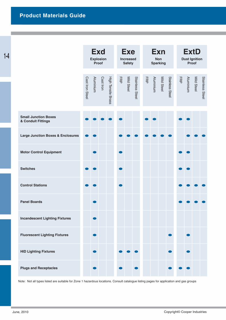
Note: Not all types listed are suitable for Zone 1 hazardous locations. Consult catalogue listing pages for application and gas groups
Small Junction Boxes& Conduit Fittings • • • • • • • • •Large Junction Boxes & Enclosures • • • • • • • • • • • •Motor Control Equipment • • • •Switches • • • • •Control Stations • • • • • • •Panel Boards • • • • •Incandescent Lighting Fixtures •Fluorescent Lighting Fixtures • • •HID Lighting Fixtures • • • • • •Plugs and Receptacles • • • • • •
Product Materials Guide
CastIronSteel
Aluminium
CastIron
HighTensile
Brass
FRP
MildSteel
StainlessSteel
FRP
Aluminium
MildSteel
StainlessSteel
Aluminium
MildSteel
StainlessSteel
FRP
ExdExplosionProof
ExeIncreasedSafety
ExnNon
Sparking
ExtDDust Ignition
Proof1-4
June, 2010 Copyright© Cooper Industries
Many liquids, gases and dusts which are generated,processed, handled, and stored in industry are combustible.When ignited they may burn rapidly and with considerableexplosive force.
The use of electrical apparatus in these areas is usuallynecessary to facilitate the handling or processing of thehazardous materials. To remove the possibility of ignitionbeing caused by the electrical apparatus, suitable precau-tions must be taken with both the equipment and the instal-lation methods used in these hazardous areas.
Improvements in electrical technology have resulted in thedevelopment of new and improved materials which havegiven rise to a considerable increase in the range of optionsavailable. These precautions are known today as Explo-sion Protection Techniques.
Growth in mining, chemical, petrochemical and associatedindustries has encouraged the introduction of newtechniques, and the Policy of Standards Australia in follow-ing closely the I.E.C. recommendations, has led to the pub-lishing of Australian Standards on these techniques.
As a result of this the users of today have at their disposal apackage of techniques which allow additional considerationsuch as environment to be taken into account when choos-ing equipment for use in hazardous locations.
A summary of the various techniques and their applicationin relation to area classification is shown in Figure 1.
All these techniques, with the exception of Exm (hermeti-cally sealed) and Exq (sand filled) are now covered by Aus-tralian Standards in relation to manufacture and certificationof equipment.
In addition, Standards Australia runs a certification schemewhereby this equipment can be type tested and certified ascomplying with a particular Australian Standard.
The use of this certification will assist users in the selectionof the correct equipment for use in hazardous locations.
In order to make a selection of equipment it is necessary tohave the hazardous area classification defined, as laid outin AS2430. However it is necessary for the classification tocontain details of the T rating and, for Zone 1, the Gasgroup of the hazardous material.
Selection of EquipmentFigure 2 shows the techniques in common Australian usagetoday, and some typical applications.
This does not mean that the other techniques are not usedand are not available in Australia or that they will not find in-creasing use there.
The growth of the industries using explosion protectedequipment have given rise to an increased interest by com-panies in local manufacture of this equipment, with the re-sult that there is available today a significant amount oflocally manufactured products using all of the techniques incommon use.
In addition, this is supplemented by imported equipmentwhich is available locally and which carries Australian certifi-cation.
The Operating EnvironmentWhen selecting equipment for use in hazardous locations, itis very easy to overlook the environmental effects on equip-ment.
However, the operating environment can cause corrosion orsimilar degradation of equipment which could cause defec-tive operation after a long period of service.
For example, the use of plastic material in a spray booth orsolvent laden atmosphere should be avoided since thechemicals may attack the plastic materials.
Conversely in the salt laden atmosphere experienced in off-shore platforms and shipping applications, the use of plasticor stainless steel is preferable to aluminum.
Crouse-Hinds Australia can give personal assistance, if re-quired, when selection of materials is being made.
Explosion Protection Techniques
1-5
Copyright© Cooper Industries June, 2010
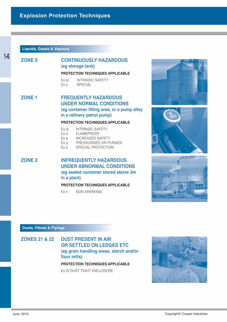
ZONE 0 CONTINUOUSLY HAZARDOUS(eg storage tank)PROTECTION TECHNIQUES APPLICABLEEx ia INTRINSIC SAFETYEx s SPECIAL
ZONE 1 FREQUENTLY HAZARDOUSUNDER NORMAL CONDITIONS(eg container filling area, or a pump alleyin a refinery petrol pump)PROTECTION TECHNIQUES APPLICABLEEx ib INTRINSIC SAFETYEx d FLAMEPROOFEx e INCREASED SAFETYEx p PRESSURISED OR PURGEDEx s SPECIAL PROTECTION
ZONE 2 INFREQUENTLY HAZARDOUSUNDER ABNORMAL CONDITIONS(eg sealed container stored above 3min a plant)PROTECTION TECHNIQUES APPLICABLEEx n NON SPARKING
ZONES 21 & 22 DUST PRESENT IN AIROR SETTLED ON LEDGES ETC(eg grain handling areas, starch and/orflour mills)PROTECTION TECHNIQUES APPLICABLEEx tD DUST TIGHT ENCLOSURE
Explosion Protection Techniques
Liquids, Gases & Vapours
Dusts, Fibres & Flyings
1-6
June, 2010 Copyright© Cooper Industries
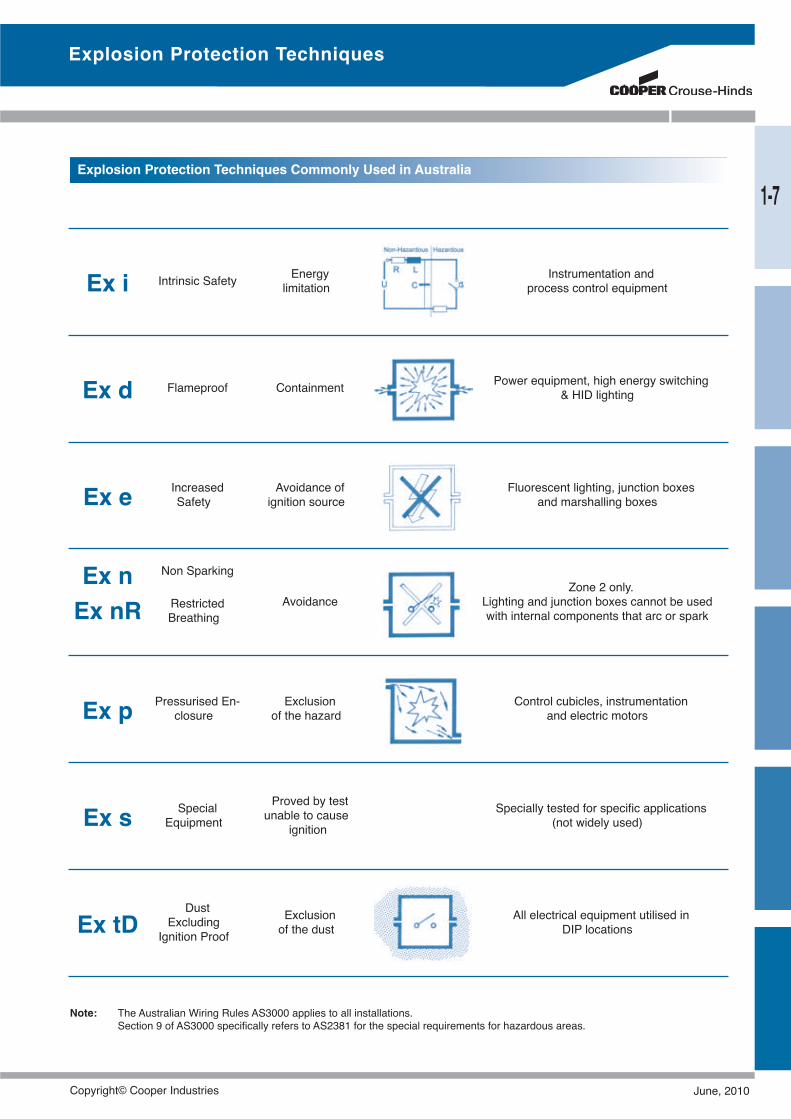
Ex i Intrinsic Safety Energylimitation
Instrumentation andprocess control equipment
Ex d Flameproof Containment Power equipment, high energy switching& HID lighting
Ex e IncreasedSafety
Avoidance ofignition source
Fluorescent lighting, junction boxesand marshalling boxes
Ex nEx nR
Non Sparking
RestrictedBreathing
AvoidanceZone 2 only.
Lighting and junction boxes cannot be usedwith internal components that arc or spark
Ex p Pressurised En-closure
Exclusionof the hazard
Control cubicles, instrumentationand electric motors
Ex s SpecialEquipment
Proved by testunable to cause
ignitionSpecially tested for specific applications
(not widely used)
Ex tDDust
ExcludingIgnition Proof
Exclusionof the dust
All electrical equipment utilised inDIP locations
Note: The Australian Wiring Rules AS3000 applies to all installations.Section 9 of AS3000 specifically refers to AS2381 for the special requirements for hazardous areas.
Explosion Protection Techniques
Explosion Protection Techniques Commonly Used in Australia
1-7
Copyright© Cooper Industries June, 2010
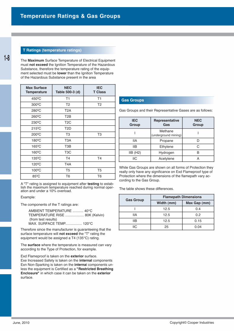
The Maximum Surface Temperature of Electrical Equipmentmust not exceed the Ignition Temperature of the HazardousSubstance, therefore the temperature rating of the equip-ment selected must be lower than the Ignition Temperatureof the Hazardous Substance present in the area
Gas Groups and their Representative Gases are as follows:
While Gas Groups are shown on all forms of Protection theyreally only have any significance on Exd Flameproof type ofProtection where the dimensions of the flamepath vary ac-cording to the Gas Group.
The table shows these differences.A "T" rating is assigned to equipment after testing to estab-lish the maximum temperature reached during normal oper-ation and under a 10% overload.Example:
The components of the T ratings are:AMBIENT TEMPERATURE ........... 40°CTEMPERATURE RISE ................... 80K (Kelvin)(from test results)MAX. SURFACE TEMP................. 120°C
Therefore since the manufacturer is guaranteeing that thesurface temperature will not exceed the "T" rating theequipment would be assigned a T4 (135°C) rating.
The surface where the temperature is measured can varyaccording to the Type of Protection, for example.
Exd Flameproof is taken on the exterior surface.Exe Increased Safety is taken on the internal componentsExn Non-Sparking is taken on the internal components un-less the equipment is Certified as a "Restricted BreathingEnclosure" in which case it can be taken on the exteriorsurface.
Max SurfaceTemperature
NECTable 500-3 (d)
IECT Class
4500C T1 T13000C T2 T22800C T2A2600C T2B2300C T2C2150C T2D2000C T3 T31800C T3A1650C T3B1600C T3C1350C T4 T41200C T4A1000C T5 T5850C T6 T6
IECGroup
RepresentativeGas
NECGroup
I Methane(underground mining) I
IIA Propane DIIB Ethylene C
IIB (H2) Hydrogen BIIC Acetylene A
Gas GroupFlamepath Dimensions
Width (mm) Max Gap (mm)I 12.5 0.4IIA 12.5 0.2IIB 12.5 0.15IIC 25 0.04
Temperature Ratings & Gas Groups
T Ratings (temperature ratings)
Gas Groups
1-8
June, 2010 Copyright© Cooper Industries
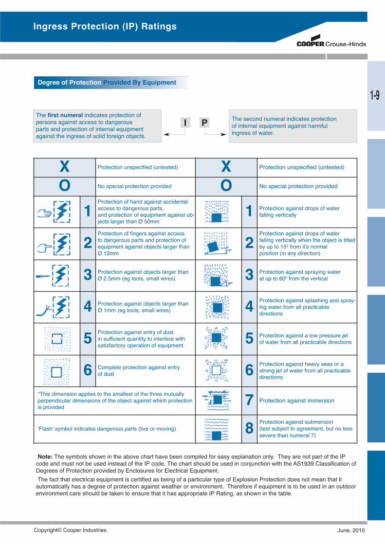
Ingress Protection (IP) Ratings
The first numeral indicates protection ofpersons against access to dangerousparts and protection of internal equipmentagainst the ingress of solid foreign objects.
The second numeral indicates protectionof internal equipment against harmfulingress of water.
I P
X Protection unspecified (untested) X Protection unspecified (untested)
O No special protection provided O No special protection provided
1Protection of hand against accidentalaccess to dangerous parts,and protection of equipment against ob-jects larger than Ø 50mm*
1 Protection against drops of waterfalling vertically
2Protection of fingers against accessto dangerous parts and protection ofequipment against objects larger thanØ 12mm
2Protection against drops of waterfalling vertically when the object is tiltedby up to 150 from it’s normalposition (in any direction)
3 Protection against objects larger thanØ 2.5mm (eg tools, small wires) 3 Protection against spraying water
at up to 600 from the vertical
4 Protection against objects larger thanØ 1mm (eg tools, small wires) 4 Protection against splashing and spray-
ing water from all practicabledirections
5 Protection against entry of dustin sufficient quantity to interfere withsatisfactory operation of equipment 5 Protection against a low pressure jet
of water from all practicable directions
6 Complete protection against entryof dust 6 Protection against heavy seas or a
strong jet of water from all practicabledirections
*This dimension applies to the smallest of the three mutuallyperpendicular dimensions of the object against which protectionis provided 7 Protection against immersion
‘Flash’ symbol indicates dangerous parts (live or moving) 8 Protection against submersion(test subject to agreement, but no lesssevere than numeral 7)
Note: The symbols shown in the above chart have been compiled for easy explanation only. They are not part of the IPcode and must not be used instead of the IP code. The chart should be used in conjunction with the AS1939 Classification ofDegrees of Protection provided by Enclosures for Electrical Equipment.The fact that electrical equipment is certified as being of a particular type of Explosion Protection does not mean that itautomatically has a degree of protection against weather or environment. Therefore if equipment is to be used in an outdoorenvironment care should be taken to ensure that it has appropriate IP Rating, as shown in the table.
Degree of Protection Provided By Equipment
1-9
Copyright© Cooper Industries June, 2010
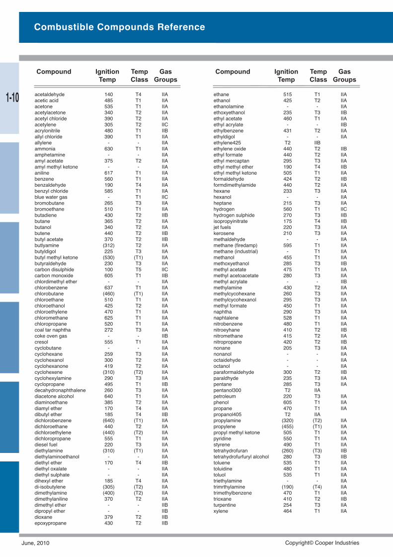
Combustible Compounds Reference
acetaldehyde 140 T4 IIAacetic acid 485 T1 IIAacetone 535 T1 IIAacetylacetone 340 T2 IIAacetyl chloride 390 T2 IIAacetylene 305 T2 IICacrylonitrile 480 T1 IIBallyl chloride 390 T1 IIAallylene - - IIAammonia 630 T1 IIAamphetamine - - IIAamyl acetate 375 T2 IIAamyl methyl ketone - - IIAaniline 617 T1 IIAbenzene 560 T1 IIAbenzaldehyde 190 T4 IIAbenzyl chloride 585 T1 IIAblue water gas - T1 IICbromobutane 265 T3 IIAbromoethane 510 T1 IIAbutadiene 430 T2 IIBbutane 365 T2 IIAbutanol 340 T2 IIAbutene 440 T2 IIBbutyl acetate 370 T2 IIBbutlyamine (312) T2 IIAbutyldigol 225 T3 IIAbutyl methyl ketone (530) (T1) IIAbutyraldehyde 230 T3 IIAcarbon disulphide 100 T5 IICcarbon monoxide 605 T1 IIBchlordimethyl ether - - IIAchlorobenzene 637 T1 IIAchlorobutane (460) (T1) IIAchloroethane 510 T1 IIAchloroethanol 425 T2 IIAchloroethylene 470 T1 IIAchloromethane 625 T1 IIAchloropropane 520 T1 IIAcoal tar naphtha 272 T3 IIAcoke oven gas - - IIBcresol 555 T1 IIAcyclobutane - - IIAcyclohexane 259 T3 IIAcyclohexanol 300 T2 IIAcyclohexanone 419 T2 IIAcyclohexene (310) (T2) IIAcyclohexylamine 290 T3 IIAcyclopropane 495 T1 IIBdecahydronaphthalene 260 T3 IIAdiacetone alcohol 640 T1 IIAdiaminoethane 385 T2 IIAdiamyl ether 170 T4 IIAdibutyl ether 185 T4 IIBdichlorobenzene (640) (T1) IIAdichloroethane 440 T2 IIAdichloroethylene (440) (T2) IIAdichloropropane 555 T1 IIAdiesel fuel 220 T3 IIAdiethylamine (310) (T1) IIAdiethylaminoethanol - - IIAdiethyl ether 170 T4 IIBdiethyl oxalate - - IIAdiethyl sulphate - - IIAdihexyl ether 185 T4 IIAdi-isobutylene (305) (T2) IIAdimethylamine (400) (T2) IIAdimethylaniline 370 T2 IIAdimethyl ether - - IIBdipropyl ether - - IIBdioxane 379 T2 IIBepoxypropane 430 T2 IIB
ethane 515 T1 IIAethanol 425 T2 IIAethanolamine - - IIAethoxyethanol 235 T3 IIBethyl acetate 460 T1 IIAethyl acrylate - - IIBethylbenzene 431 T2 IIAethyldigol - - IIAethylene425 T2 IIBethylene oxide 440 T2 IIBethyl formate 440 T2 IIAethyl mercaptan 295 T3 IIAethyl methyl ether 190 T4 IIBethyl methyl ketone 505 T1 IIAformaldehyde 424 T2 IIBformdimethylamide 440 T2 IIAhexane 233 T3 IIAhexanol - - IIAheptane 215 T3 IIAhydrogen 560 T1 IIChydrogen sulphide 270 T3 IIBisopropyinitrate 175 T4 IIBjet fuels 220 T3 IIAkerosene 210 T3 IIAmethaldehyde - - IIAmethane (firedamp) 595 T1 IIAmethane (industrial) - T1 IIAmethanol 455 T1 IIAmethoxyethanol 285 T3 IIBmethyl acetate 475 T1 IIAmethyl acetoacetate 280 T3 IIAmethyl acrylate - - IIBmethylamine 430 T2 IIAmethylcycohexane 260 T3 IIAmethylcycohexanol 295 T3 IIAmethyl formate 450 T1 IIAnaphtha 290 T3 IIAnaphtalene 528 T1 IIAnitrobenzene 480 T1 IIAnitroeyhane 410 T2 IIBnitromethane 415 T2 IIAnitropropane 420 T2 IIBnonane 205 T3 IIAnonanol - - IIAoctaidehyde - - IIAoctanol - - IIAparaformaldehyde 300 T2 IIBparaldhyde 235 T3 IIApentane 285 T3 IIApentanol300 T2 IIApetroleum 220 T3 IIAphenol 605 T1 IIApropane 470 T1 IIApropanol405 T2 IIApropylamine (320) (T2) IIApropylene (455) (T1) IIApropyl methyl ketone 505 T1 IIApyridine 550 T1 IIAstyrene 490 T1 IIAtetrahydrofuran (260) (T3) IIBtetrahydrofurfuryl alcohol 280 T3 IIBtoluene 535 T1 IIAtoluidine 480 T1 IIAtoluol 535 T1 IIAtriethylamine - - IIAtrimrthylamine (190) (T4) IIAtrimethylbenzene 470 T1 IIAtrioxane 410 T2 IIBturpentine 254 T3 IIAxylene 464 T1 IIA
Compound Ignition Temp GasTemp Class Groups
Compound Ignition Temp GasTemp Class Groups
1-10
June, 2010 Copyright© Cooper Industries
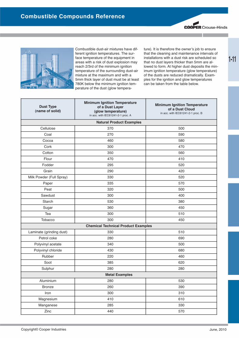
Combustible dust-air mixtures have dif-ferent ignition temperatures. The sur-face temperature of the equipment inareas with a risk of dust explosion mayreach 2/3rd of the minimum ignitiontemperature of the surrounding dust-airmixture at the maximum and with a5mm thick layer of dust must be at least780K below the minimum ignition tem-perature of the dust (glow tempera-
ture). It is therefore the owner’s job to ensurethat the cleaning and maintenance intervals ofinstallations with a dust risk are scheduled sothat no dust layers thicker than 5mm are al-lowed to form. At higher dust deposits the min-imum ignition temperature (glow temperature)of the dusts are reduced dramatically. Exam-ples for the ignition and glow temperaturescan be taken from the table below.
Dust Type(name of solid)
Minimum Ignition Temperatureof a Dust Layer
(glow temperature)in acc. with IEC61241-2-1 proc. A
Minimum Ignition Temperatureof a Dust Cloud
in acc. with IEC61241-2-1 proc. B
Natural Product ExamplesCellulose 370 500Coal 270 590Cocoa 460 580Cork 300 470Cotton 350 560Flour 470 410Fodder 295 520Grain 290 420
Milk Powder (Full Spray) 330 520Paper 335 570Peat 320 500
Sawdust 300 400Starch 530 380Sugar 360 450Tea 300 510
Tobacco 300 450Chemical Technical Product Examples
Laminate (grinding dust) 330 510Petrol coke 280 690
Polyvinyl acetate 340 500Polyvinyl chloride 430 680
Rubber 220 460Soot 385 620Sulphur 280 280
Metal ExamplesAluminium 280 530Bronze 260 390Iron 300 310
Magnesium 410 610Manganese 285 330
Zinc 440 570
Combustible Compounds Reference
1-11
Copyright© Cooper Industries June, 2010
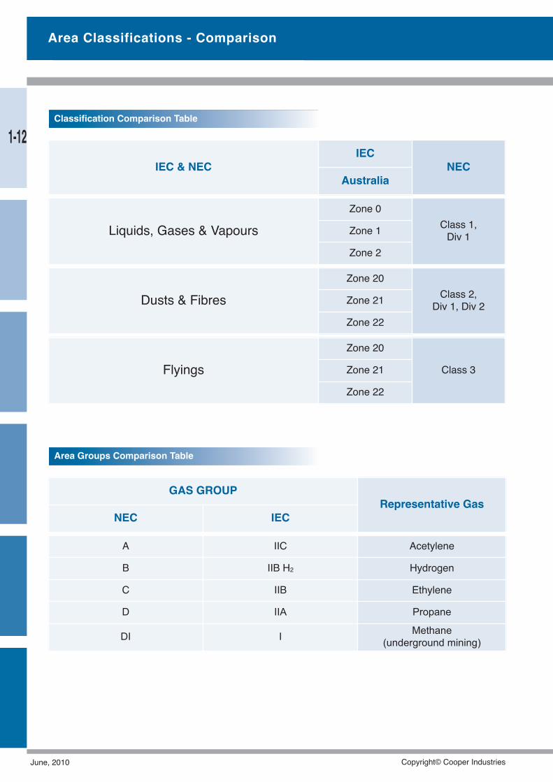
IEC & NECIEC
NECAustralia
Dusts & FibresZone 20
Class 2,Div 1, Div 2Zone 21
Zone 22
FlyingsZone 20
Class 3Zone 21
Zone 22
Liquids, Gases & VapoursZone 0
Class 1,Div 1Zone 1
Zone 2
GAS GROUPRepresentative Gas
NEC IEC
A IIC Acetylene
B IIB H2 Hydrogen
C IIB Ethylene
D IIA Propane
DI I Methane(underground mining)
Area Groups Comparison Table
Classification Comparison Table
Area Classifications - Comparison
1-12
June, 2010 Copyright© Cooper Industries
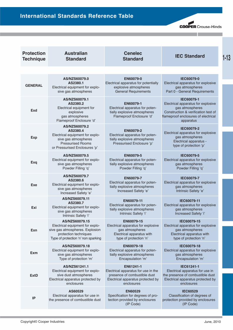
ProtectionTechnique
AustralianStandard
CenelecStandard IEC Standard
GENERAL
AS/NZS60079.0AS2380.1
Electrical equipment for explo-sive gas atmospheres
EN60079-0Electrical apparatus for potentially
explosive atmospheresGeneral Requirements
IEC60079-0Electrical apparatus for explosive
gas atmospheresPart 0 - General Requirements
Exd
AS/NZS60079.1AS2380.2
Electrical equipment forexplosive
gas atmospheresFlameproof Enclosure ‘d’
EN60079-1Electrical apparatus for poten-tially explosive atmospheresFlameproof Enclosure ‘d’
IEC60079-1Electrical apparatus for explosive
gas atmospheresConstruction & verification test offlameproof enclosures of electrical
apparatus
Exp
AS/NZS60079.2AS2380.4
Electrical equipment for explo-sive gas atmospheresPressurised Rooms
or Pressurised Enclosures ‘p’
EN60079-2Electrical apparatus for poten-tially explosive atmospheresPressurised Enclosure ‘p’
IEC60079-2Electrical apparatus for explosive
gas atmospheresElectrical apparatus -type of protection ‘p’
Exq
AS/NZS60079.5Electrical equipment for explo-
sive gas atmospheresPowder Filling ‘q’
EN60079-5Electrical apparatus for poten-tially explosive atmospheres
Powder Filling ‘q’
IEC60079-5Electrical apparatus for explosive
gas atmospheresPowder Filling ‘q’
Exe
AS/NZS60079.7AS2380.6
Electrical equipment for explo-sive gas atmospheresIncreased Safety ‘e’
EN60079-7Electrical apparatus for poten-tially explosive atmospheres
Increased Safety ‘e’
IEC60079-7Electrical apparatus for explosive
gas atmospheresIntrinsic Safety ‘e’
Exi
AS/NZS60079.11AS2380.7
Electrical equipment for explo-sive gas atmospheresIntrinsic Safety ‘i’
EN60079-11Electrical apparatus for poten-tially explosive atmospheres
Intrinsic Safety ‘i’
IEC60079-11Electrical apparatus for explosive
gas atmospheresIncreased Safety ‘i’
Exn
AS/NZS60079.15Electrical equipment for explo-
sive gas atmospheres. Explosionprotection techniques
Type of protection ‘n’ non sparking
EN60079-15Electrical apparatus for explosive
gas atmospheresElectrical apparatus withtype of protection ‘n’
IEC60079-15Electrical apparatus for explosive
gas atmospheresElectrical apparatus withtype of protection ‘n’
Exm
AS/NZS60079.18Electrical equipment for explo-
sive gas atmospheresType of protection ‘m’
EN60079-18Electrical apparatus for poten-tially explosive atmospheres
Encapsulation ‘m’
IEC60079-18Electrical apparatus for explosive
gas atmospheresEncapsulation ‘m’
ExtD
AS/NZS61241.1Electrical equipment for explo-sive dust atmospheres
Electrical apparatus protected byenclosures
EN61241-1Electrical apparatus for use in thepresence of combustible dustElectrical apparatus protected by
enclosures
IEC61241-1Electrical apparatus for use in
the presence of combustible dustElectrical apparatus protected by
enclosures
IP
AS60529Electrical apparatus for use in
the presence of combustible dust
EN60529Specification for degrees of pro-tection provided by enclosures
(IP Code)
IEC60529Classification of degrees of
protection provided by enclosures(IP Code)
International Standards Reference Table
1-13
Copyright© Cooper Industries June, 2010
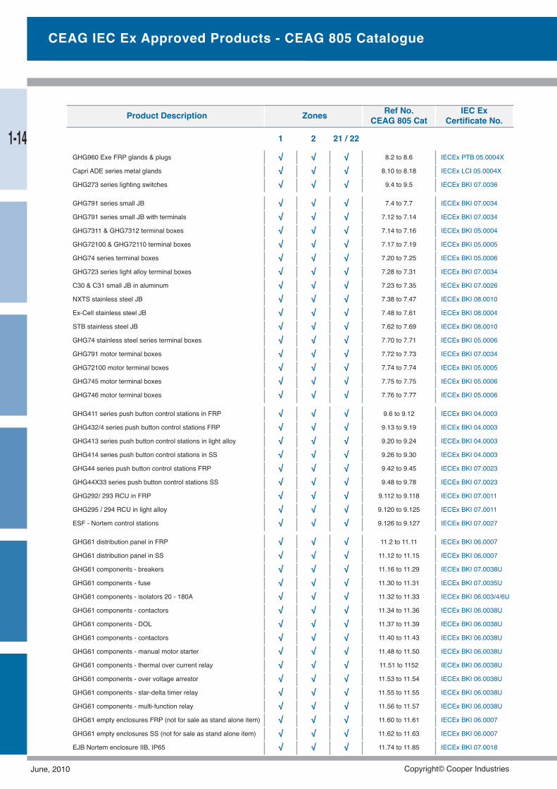
CEAG IEC Ex Approved Products - CEAG 805 Catalogue
GHG791 series small JB √ √ √ 7.4 to 7.7 IECEx BKI 07.0034
GHG791 series small JB with terminals √ √ √ 7.12 to 7.14 IECEx BKI 07.0034
GHG7311 & GHG7312 terminal boxes √ √ √ 7.14 to 7.16 IECEx BKI 05.0004
GHG72100 & GHG72110 terminal boxes √ √ √ 7.17 to 7.19 IECEx BKI 05.0005
GHG74 series terminal boxes √ √ √ 7.20 to 7.25 IECEx BKI 05.0006
GHG723 series light alloy terminal boxes √ √ √ 7.28 to 7.31 IECEx BKI 07.0034
C30 & C31 small JB in aluminum √ √ √ 7.23 to 7.35 IECEx BKI 07.0026
NXTS stainless steel JB √ √ √ 7.38 to 7.47 IECEx BKI 08.0010
Ex-Cell stainless steel JB √ √ √ 7.48 to 7.61 IECEx BKI 08.0004
STB stainless steel JB √ √ √ 7.62 to 7.69 IECEx BKI 08.0010
GHG74 stainless steel series terminal boxes √ √ √ 7.70 to 7.71 IECEx BKI 05.0006
GHG791 motor terminal boxes √ √ √ 7.72 to 7.73 IECEx BKI 07.0034
GHG72100 motor terminal boxes √ √ √ 7.74 to 7.74 IECEx BKI 05.0005
GHG745 motor terminal boxes √ √ √ 7.75 to 7.75 IECEx BKI 05.0006
GHG746 motor terminal boxes √ √ √ 7.76 to 7.77 IECEx BKI 05.0006
GHG960 Exe FRP glands & plugs √ √ √ 8.2 to 8.6 IECEx PTB 05.0004X
Capri ADE series metal glands √ √ √ 8.10 to 8.18 IECEx LCI 05.0004X
GHG273 series lighting switches √ √ √ 9.4 to 9.5 IECEx BKI 07.0036
GHG411 series push button control stations in FRP √ √ √ 9.6 to 9.12 IECEx BKI 04.0003
GHG432/4 series push button control stations FRP √ √ √ 9.13 to 9.19 IECEx BKI 04.0003
GHG413 series push button control stations in light alloy √ √ √ 9.20 to 9.24 IECEx BKI 04.0003
GHG414 series push button control stations in SS √ √ √ 9.26 to 9.30 IECEx BKI 04.0003
GHG44 series push button control stations FRP √ √ √ 9.42 to 9.45 IECEx BKI 07.0023
GHG44X33 series push button control stations SS √ √ √ 9.48 to 9.78 IECEx BKI 07.0023
GHG292/ 293 RCU in FRP √ √ √ 9.112 to 9.118 IECEx BKI 07.0011
GHG295 / 294 RCU in light alloy √ √ √ 9.120 to 9.125 IECEx BKI 07.0011
ESF - Nortem control stations √ √ √ 9.126 to 9.127 IECEx BKI 07.0027
GHG61 distribution panel in FRP √ √ √ 11.2 to 11.11 IECEx BKI 06.0007
GHG61 distribution panel in SS √ √ √ 11.12 to 11.15 IECEx BKI 06.0007
GHG61 components - breakers √ √ √ 11.16 to 11.29 IECEx BKI 07.0038U
GHG61 components - fuse √ √ √ 11.30 to 11.31 IECEx BKI 07.0035U
GHG61 components - isolators 20 - 180A √ √ √ 11.32 to 11.33 IECEx BKI 06.003/4/6U
GHG61 components - contactors √ √ √ 11.34 to 11.36 IECEx BKI 06.0038U
GHG61 components - DOL √ √ √ 11.37 to 11.39 IECEx BKI 06.0038U
GHG61 components - contactors √ √ √ 11.40 to 11.43 IECEx BKI 06.0038U
GHG61 components - manual motor starter √ √ √ 11.48 to 11.50 IECEx BKI 06.0038U
GHG61 components - thermal over current relay √ √ √ 11.51 to 1152 IECEx BKI 06.0038U
GHG61 components - over voltage arrestor √ √ √ 11.53 to 11.54 IECEx BKI 06.0038U
GHG61 components - star-delta timer relay √ √ √ 11.55 to 11.55 IECEx BKI 06.0038U
GHG61 components - multi-function relay √ √ √ 11.56 to 11.57 IECEx BKI 06.0038U
GHG61 empty enclosures FRP (not for sale as stand alone item) √ √ √ 11.60 to 11.61 IECEx BKI 06.0007
GHG61 empty enclosures SS (not for sale as stand alone item) √ √ √ 11.62 to 11.63 IECEx BKI 06.0007
EJB Nortem enclosure IIB, IP65 √ √ √ 11.74 to 11.85 IECEx BKI 07.0018
Product Description Zones Ref No.CEAG 805 Cat
IEC ExCertificate No.
1 2 21 / 221-14
June, 2010 Copyright© Cooper Industries
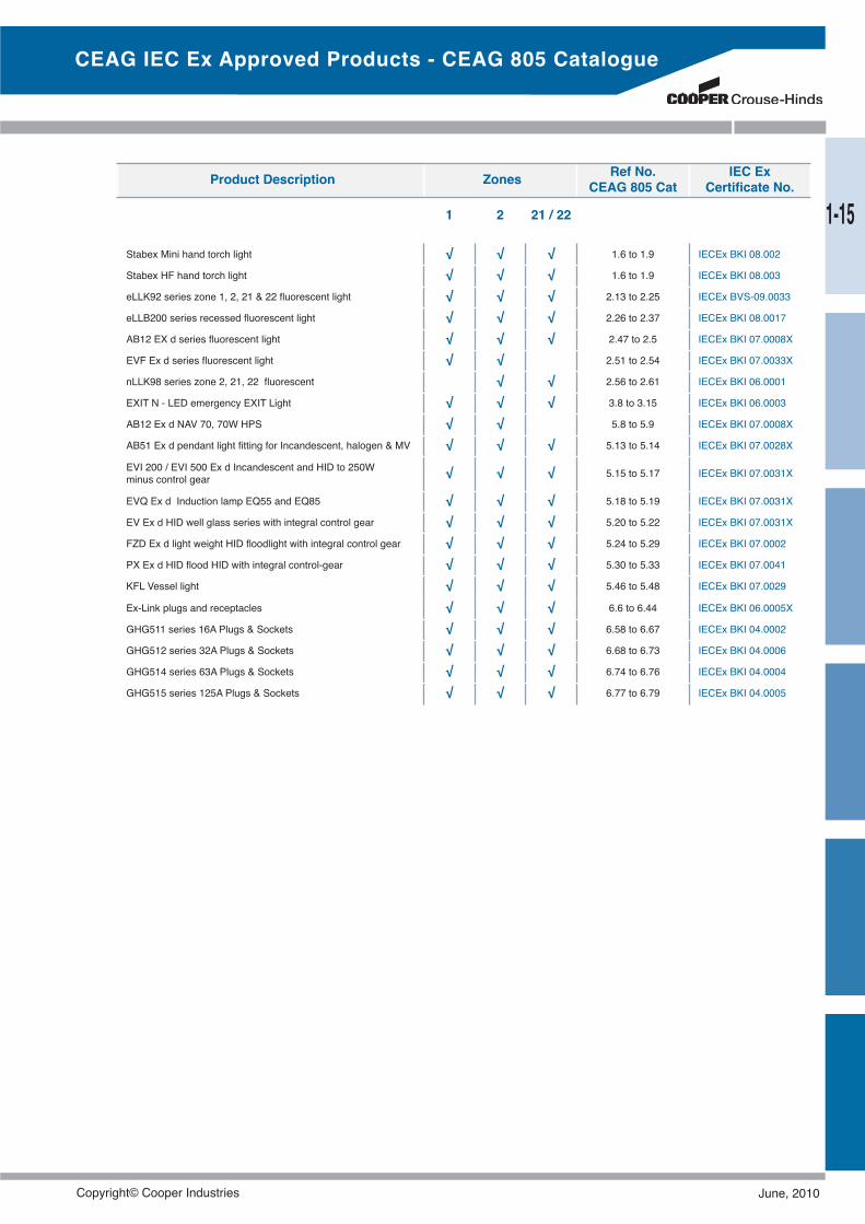
Ex-Link plugs and receptacles √ √ √ 6.6 to 6.44 IECEx BKI 06.0005X
GHG511 series 16A Plugs & Sockets √ √ √ 6.58 to 6.67 IECEx BKI 04.0002
GHG512 series 32A Plugs & Sockets √ √ √ 6.68 to 6.73 IECEx BKI 04.0006
GHG514 series 63A Plugs & Sockets √ √ √ 6.74 to 6.76 IECEx BKI 04.0004
GHG515 series 125A Plugs & Sockets √ √ √ 6.77 to 6.79 IECEx BKI 04.0005
Stabex Mini hand torch light √ √ √ 1.6 to 1.9 IECEx BKI 08.002
Stabex HF hand torch light √ √ √ 1.6 to 1.9 IECEx BKI 08.003
eLLK92 series zone 1, 2, 21 & 22 fluorescent light √ √ √ 2.13 to 2.25 IECEx BVS-09.0033
eLLB200 series recessed fluorescent light √ √ √ 2.26 to 2.37 IECEx BKI 08.0017
AB12 EX d series fluorescent light √ √ √ 2.47 to 2.5 IECEx BKI 07.0008X
EVF Ex d series fluorescent light √ √ 2.51 to 2.54 IECEx BKI 07.0033X
nLLK98 series zone 2, 21, 22 fluorescent √ √ 2.56 to 2.61 IECEx BKI 06.0001
EXIT N - LED emergency EXIT Light √ √ √ 3.8 to 3.15 IECEx BKI 06.0003
AB12 Ex d NAV 70, 70W HPS √ √ 5.8 to 5.9 IECEx BKI 07.0008X
AB51 Ex d pendant light fitting for Incandescent, halogen & MV √ √ √ 5.13 to 5.14 IECEx BKI 07.0028X
EVI 200 / EVI 500 Ex d Incandescent and HID to 250Wminus control gear √ √ √ 5.15 to 5.17 IECEx BKI 07.0031X
EVQ Ex d Induction lamp EQ55 and EQ85 √ √ √ 5.18 to 5.19 IECEx BKI 07.0031X
EV Ex d HID well glass series with integral control gear √ √ √ 5.20 to 5.22 IECEx BKI 07.0031X
FZD Ex d light weight HID floodlight with integral control gear √ √ √ 5.24 to 5.29 IECEx BKI 07.0002
PX Ex d HID flood HID with integral control-gear √ √ √ 5.30 to 5.33 IECEx BKI 07.0041
KFL Vessel light √ √ √ 5.46 to 5.48 IECEx BKI 07.0029
Product Description Zones Ref No.CEAG 805 Cat
IEC ExCertificate No.
1 2 21 / 22
CEAG IEC Ex Approved Products - CEAG 805 Catalogue
1-15
Copyright© Cooper Industries June, 2010
Fittings
When it comes to the proper termination of cable,the correct use of fittings is as important as the equipmentitself. Incorrect application will render the installationineffective and could be dangerous.Our range of certified adaptors, reducers, conduit sealsand glands provides the hazardous and arduous indus-tries with a wide selection to suit many applications.Crouse-Hind’s fittings are available in Nickel plated brassas standard and on request, in stainless steel.
June, 2010 Copyright© Cooper Industries
2-1
Fittings
Cable GlandsCH Nylon Weatherproof ..................................................2-2TUA Unarmoured Weatherproof......................................2-3TWA Steel Wire Armoured Weatherproof........................2-4ADE1F Ex d, Ex e, Ex tD Steel Wire Armoured..........2-5TWAB Ex d, Ex e, Ex tD Steel Wire Armoured ..........2-6TWAE Ex e, Ex tD Steel Wire Armoured ..................2-7TWAX Ex d, Ex e, Ex tD Steel Wire Armoured ........2-8ADE4F Exd, Ex e, Ex td Steel Wire Armoured ........2-9Cable Gland Accessories ....................................2-10
Stopping PlugsEx d, Ex e DIP ................................................................2-11
AdaptorsEx d, DIP ........................................................................2-12
ReducersEx d, DIP ........................................................................2-16
UnionsEx d, DIP ........................................................................2-17
NipplesEx d, DIP ........................................................................2-18
Conduit SealsEx d, DIP ........................................................................2-19
Sealing CompoundSealing Compound ........................................................2-20
Inspection Elbows & TeesExd, DIP ........................................................................2-21
Copyright© Cooper Industries June, 2010
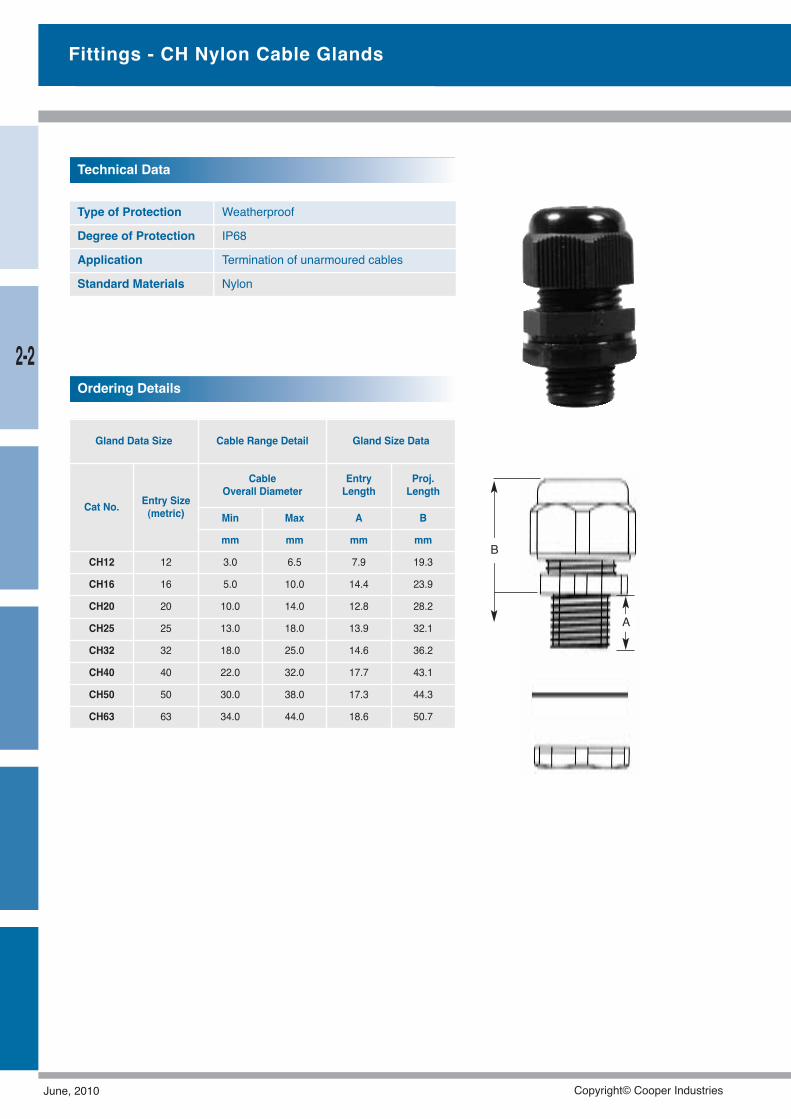
Type of Protection Weatherproof
Degree of Protection IP68
Application Termination of unarmoured cables
Standard Materials Nylon
A
B
Gland Data Size Cable Range Detail Gland Size Data
Cat No. Entry Size(metric)
CableOverall Diameter
EntryLength
Proj.Length
Min Max A B
mm mm mm mm
CH12 12 3.0 6.5 7.9 19.3
CH16 16 5.0 10.0 14.4 23.9
CH20 20 10.0 14.0 12.8 28.2
CH25 25 13.0 18.0 13.9 32.1
CH32 32 18.0 25.0 14.6 36.2
CH40 40 22.0 32.0 17.7 43.1
CH50 50 30.0 38.0 17.3 44.3
CH63 63 34.0 44.0 18.6 50.7
Technical Data
Ordering Details
Fittings - CH Nylon Cable Glands
2-2
June, 2010 Copyright© Cooper Industries

Fittings - TUA Terminator® Cable Glands
Gland Size Data Gland Size Data
Cat No. Entry Size(metric)
Cable Hexagon Size
OverallDiameter
AcrossFlats
AcrossCnrs
Min Max A B C D
mm mm mm mm mm mm
TUA12M6 12 3.5 6.5 5.0 11.0 12.0 14.0
TUA16M9 16 5.5 9.5 6.0 13.0 16.0 18.0
TUA1M13 20 8.5 13.0 6.0 14.0 20.0 22.0
TUA2M17 25 12.0 17.0 7.0 16.0 25.0 27.0
TUA3M22 32 15.0 22.0 8.0 20.0 32.0 35.0
TUA4M28 40 19.5 28.0 8.0 23.0 40.0 44.0
TUA5M36 50 25.5 36.0 9.0 27.0 50.0 54.0
TUA6M46 63 33.0 46.0 10.0 32.0 63.0 67.0
TUA7M53 75 37.0 53.0 18.0 41.4 80.0 85.0
Type of Protection Weatherproof
Degree of Protection IP66/67
Application Termination of unarmoured cables
Standard Materials Brass, nickel plated
Options
Stainless steel(add suffix SS to part no.,minimum order qty’s applicable)Other thread types available upon request
Technical Data
Ordering Details
2-3
Copyright© Cooper Industries June, 2010
Fittings - TWA Terminator® Cable Glands
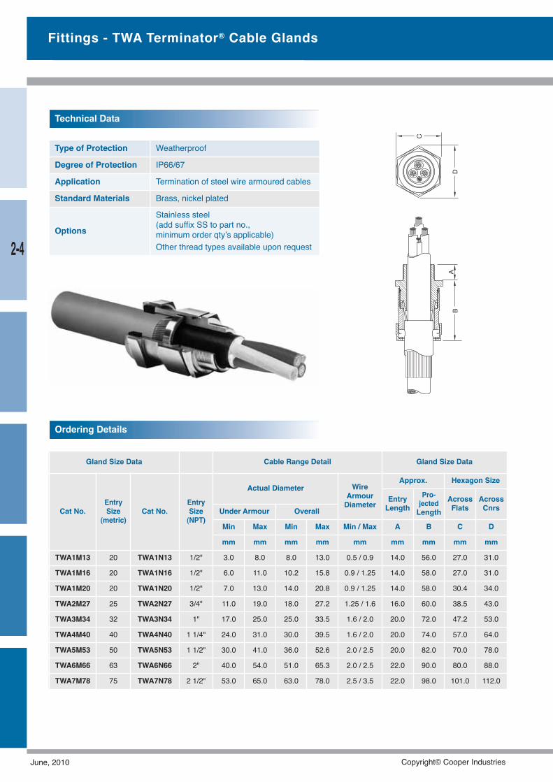
Type of Protection Weatherproof
Degree of Protection IP66/67
Application Termination of steel wire armoured cables
Standard Materials Brass, nickel plated
Options
Stainless steel(add suffix SS to part no.,minimum order qty’s applicable)Other thread types available upon request
Gland Size Data Cable Range Detail Gland Size Data
Cat No.EntrySize
(metric)Cat No.
EntrySize(NPT)
Actual Diameter WireArmourDiameter
Approx. Hexagon Size
EntryLength
Pro-jectedLength
AcrossFlats
AcrossCnrsUnder Armour Overall
Min Max Min Max Min / Max A B C D
mm mm mm mm mm mm mm mm mm
TWA1M13 20 TWA1N13 1/2" 3.0 8.0 8.0 13.0 0.5 / 0.9 14.0 56.0 27.0 31.0
TWA1M16 20 TWA1N16 1/2" 6.0 11.0 10.2 15.8 0.9 / 1.25 14.0 58.0 27.0 31.0
TWA1M20 20 TWA1N20 1/2" 7.0 13.0 14.0 20.8 0.9 / 1.25 14.0 58.0 30.4 34.0
TWA2M27 25 TWA2N27 3/4" 11.0 19.0 18.0 27.2 1.25 / 1.6 16.0 60.0 38.5 43.0
TWA3M34 32 TWA3N34 1" 17.0 25.0 25.0 33.5 1.6 / 2.0 20.0 72.0 47.2 53.0
TWA4M40 40 TWA4N40 1 1/4" 24.0 31.0 30.0 39.5 1.6 / 2.0 20.0 74.0 57.0 64.0
TWA5M53 50 TWA5N53 1 1/2" 30.0 41.0 36.0 52.6 2.0 / 2.5 20.0 82.0 70.0 78.0
TWA6M66 63 TWA6N66 2" 40.0 54.0 51.0 65.3 2.0 / 2.5 22.0 90.0 80.0 88.0
TWA7M78 75 TWA7N78 2 1/2" 53.0 65.0 63.0 78.0 2.5 / 3.5 22.0 98.0 101.0 112.0
Ordering Details
Technical Data
2-4
June, 2010 Copyright© Cooper Industries
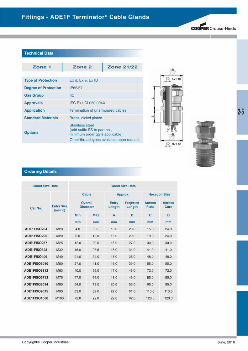
Fittings - ADE1F Terminator® Cable Glands
Type of Protection Ex d, Ex e, Ex tD
Degree of Protection IP66/67
Gas Group IIC
Approvals IEC Ex LCI 050 004X
Application Termination of unarmoured cables
Standard Materials Brass, nickel plated
Options
Stainless steel(add suffix SS to part no.,minimum order qty’s applicable)Other thread types available upon request
Gland Size Data Gland Size Data
Cat No. Entry Size(metric)
Cable Approx. Hexagon Size
OverallDiameter
EntryLength
ProjectedLength
AcrossFlats
AcrossCnrs
Min Max A B C D
mm mm mm mm mm mm
ADE1FISO204 M20 4.0 8.5 15.0 20.0 15.0 24.0
ADE1FISO205 M20 6.0 12.0 15.0 20.0 19.0 24.0
ADE1FISO257 M25 12.0 20.5 15.0 27.0 30.0 30.0
ADE1FISO328 M32 16.0 27.5 15.0 34.0 41.0 41.0
ADE1FISO409 M40 21.0 34.0 15.0 36.0 48.0 48.0
ADE1FISO5010 M50 27.0 41.0 16.0 39.0 55.0 55.0
ADE1FISO6312 M63 40.0 56.0 17.0 43.0 72.0 72.0
ADE1FISO5713 M75 47.0 65.0 18.0 49.0 85.0 85.0
ADE1FISO8014 M80 54.0 73.0 20.0 56.0 95.0 95.0
ADE1FISO9015 M90 63.0 82.0 22.0 61.0 110.0 110.0
ADE1FISO1006 M100 72.0 92.0 22.0 62.0 120.0 120.0
Technical Data
Ordering Details
Zone 1 Zone 2 Zone 21/22
2-5
Copyright© Cooper Industries June, 2010
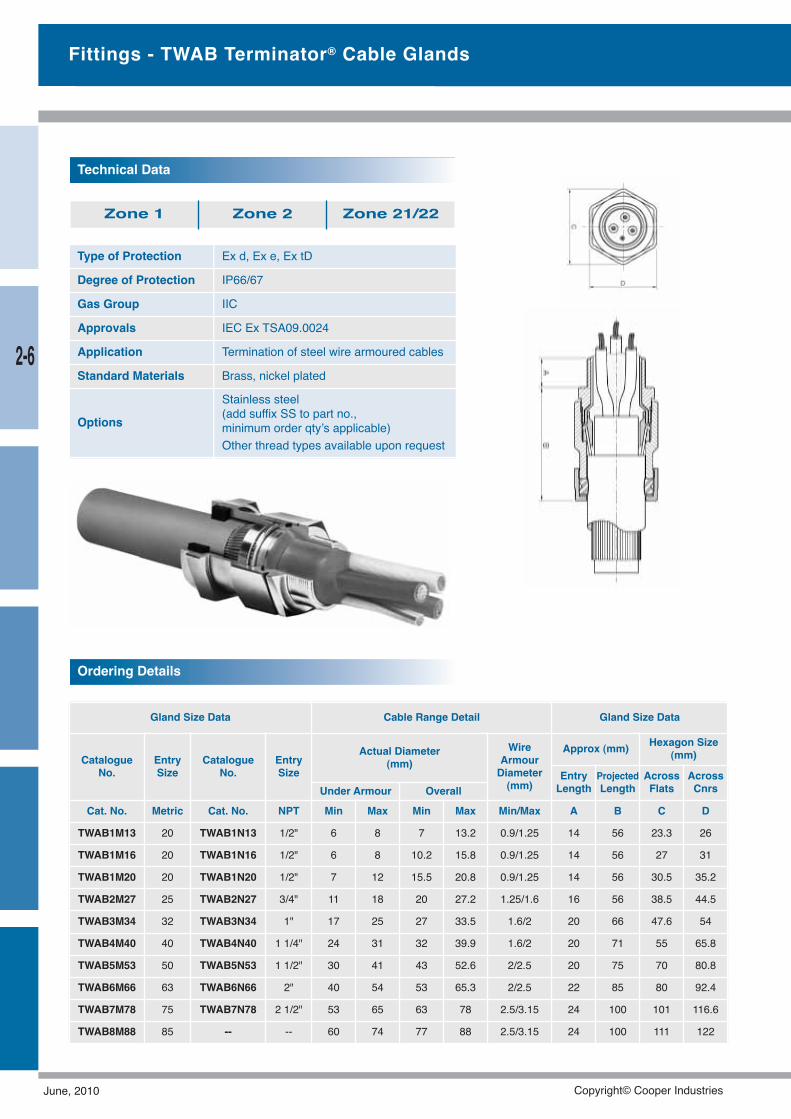
Ordering Details
Type of Protection Ex d, Ex e, Ex tD
Degree of Protection IP66/67
Gas Group IIC
Approvals IEC Ex TSA09.0024
Application Termination of steel wire armoured cables
Standard Materials Brass, nickel plated
Options
Stainless steel(add suffix SS to part no.,minimum order qty’s applicable)Other thread types available upon request
Technical Data
Zone 1 Zone 2 Zone 21/22
Fittings - TWAB Terminator® Cable Glands
Gland Size Data Cable Range Detail Gland Size Data
CatalogueNo.
EntrySize
CatalogueNo.
EntrySize
Actual Diameter(mm)
WireArmourDiameter(mm)
Approx (mm) Hexagon Size(mm)
EntryLength
ProjectedLength
AcrossFlats
AcrossCnrsUnder Armour Overall
Cat. No. Metric Cat. No. NPT Min Max Min Max Min/Max A B C D
TWAB1M13 20 TWAB1N13 1/2" 6 8 7 13.2 0.9/1.25 14 56 23.3 26
TWAB1M16 20 TWAB1N16 1/2" 6 8 10.2 15.8 0.9/1.25 14 56 27 31
TWAB1M20 20 TWAB1N20 1/2" 7 12 15.5 20.8 0.9/1.25 14 56 30.5 35.2
TWAB2M27 25 TWAB2N27 3/4" 11 18 20 27.2 1.25/1.6 16 56 38.5 44.5
TWAB3M34 32 TWAB3N34 1" 17 25 27 33.5 1.6/2 20 66 47.6 54
TWAB4M40 40 TWAB4N40 1 1/4" 24 31 32 39.9 1.6/2 20 71 55 65.8
TWAB5M53 50 TWAB5N53 1 1/2" 30 41 43 52.6 2/2.5 20 75 70 80.8
TWAB6M66 63 TWAB6N66 2" 40 54 53 65.3 2/2.5 22 85 80 92.4
TWAB7M78 75 TWAB7N78 2 1/2" 53 65 63 78 2.5/3.15 24 100 101 116.6
TWAB8M88 85 -- -- 60 74 77 88 2.5/3.15 24 100 111 122
2-6
June, 2010 Copyright© Cooper Industries
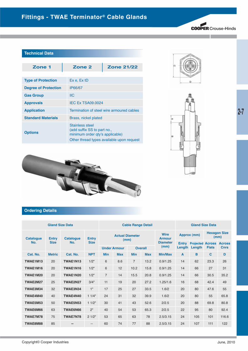
Ordering Details
Type of Protection Ex e, Ex tD
Degree of Protection IP66/67
Gas Group IIC
Approvals IEC Ex TSA09.0024
Application Termination of steel wire armoured cables
Standard Materials Brass, nickel plated
Options
Stainless steel(add suffix SS to part no.,minimum order qty’s applicable)Other thread types available upon request
Technical Data
Zone 1 Zone 2 Zone 21/22
Fittings - TWAE Terminator® Cable Glands
Gland Size Data Cable Range Detail Gland Size Data
CatalogueNo.
EntrySize
CatalogueNo.
EntrySize
Actual Diameter(mm)
WireArmourDiameter(mm)
Approx (mm) Hexagon Size(mm)
EntryLength
ProjectedLength
AcrossFlats
AcrossCnrsUnder Armour Overall
Cat. No. Metric Cat. No. NPT Min Max Min Max Min/Max A B C D
TWAE1M13 20 TWAE1N13 1/2" 6 8.6 7 13.2 0.9/1.25 14 62 23.3 26
TWAE1M16 20 TWAE1N16 1/2" 6 12 10.2 15.8 0.9/1.25 14 66 27 31
TWAE1M20 20 TWAE1N20 1/2" 7 14 15.5 20.8 0.9/1.25 14 66 30.5 35.2
TWAE2M27 25 TWAE2N27 3/4" 11 19 20 27.2 1.25/1.6 16 68 42.4 49
TWAE3M34 32 TWAE3N34 1" 17 25 27 33.5 1.6/2 20 80 47.6 55
TWAE4M40 40 TWAE4N40 1 1/4" 24 31 32 39.9 1.6/2 20 80 55 65.8
TWAE5M53 50 TWAE5N53 1 1/2" 30 41 43 52.6 2/2.5 20 88 69.8 80.8
TWAE6M66 63 TWAE6N66 2" 40 54 53 65.3 2/2.5 22 95 80 92.4
TWAE7M78 75 TWAE7N78 2 1/2" 53 65 63 78 2.5/3.15 24 105 101 116.6
TWAE8M88 85 -- -- 60 74 77 88 2.5/3.15 24 107 111 122
2-7
Copyright© Cooper Industries June, 2010
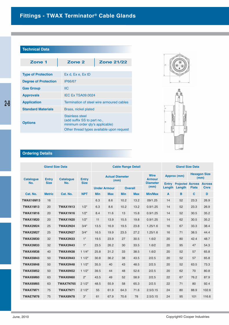
Ordering Details
Type of Protection Ex d, Ex e, Ex tD
Degree of Protection IP66/67
Gas Group IIC
Approvals IEC Ex TSA09.0024
Application Termination of steel wire armoured cables
Standard Materials Brass, nickel plated
Options
Stainless steel(add suffix SS to part no.,minimum order qty’s applicable)Other thread types available upon request
Technical Data
Zone 1 Zone 2 Zone 21/22
Fittings - TWAX Terminator® Cable Glands
Gland Size Data Cable Range Detail Gland Size Data
CatalogueNo.
EntrySize
CatalogueNo.
EntrySize
Actual Diameter(mm)
WireArmourDiameter(mm)
Approx (mm) Hexagon Size(mm)
EntryLength
ProjectedLength
AcrossFlats
AcrossCnrsUnder Armour Overall
Cat. No. Metric Cat. No. NPT Min Max Min Max Min/Max A B C D
TWAX16M13 16 6.3 8.6 10.2 13.2 09/1.25 14 52 23.3 26.9
TWAX1M13 20 TWAX1N13 1/2" 6.3 8.6 10.2 13.2 0.9/1.25 14 52 23.3 26.9
TWAX1M16 20 TWAX1N16 1/2" 8.4 11.6 13 15.8 0.9/1.25 14 52 30.5 35.2
TWAX1M20 20 TWAX1N20 1/2" 11 13.9 15.5 19.8 0.9/1.25 14 62 30.5 35.2
TWAX2M24 25 TWAX2N24 3/4" 13.5 16.9 19.5 23.8 1.25/1.6 16 67 33.3 38.4
TWAX2M27 25 TWAX2N27 3/4" 16.5 19.9 23.5 27.2 1.25/1.6 16 71 38.5 44.4
TWAX3M30 32 TWAX3N33 1" 19.5 23.9 27 30.5 1.6/2 20 80 42.4 48.7
TWAX3M33 32 TWAX3N43 1" 23.5 26.2 30 33.5 1.6/2 20 95 47 54.3
TWAX4M38 40 TWAX4N38 1 1/4" 25.8 31.2 33 38.5 1.6/2 20 52 57 65.8
TWAX5M43 50 TWAX5N43 1 1/2" 30.8 36.2 38 43.5 2/2.5 20 52 57 65.8
TWAX5M48 50 TWAX5N48 1 1/2" 35.5 40 43 48.5 2/2.5 20 52 63.5 73.3
TWAX5M52 50 TWAX6N52 1 1/2" 39.5 44 48 52.6 2/2.5 20 62 70 80.8
TWAX6M60 63 TWAX6N60 2" 43.5 49 52 58.9 2/2.5 22 67 76.2 87.9
TWAX6M65 63 TWAX7N765 2 1/2" 48.5 55.9 58 65.3 2/2.5 22 71 80 92.4
TWAX7M71 75 TWAX7N71 2 1/2" 55 61.9 64.3 71.6 2.5/3.15 24 80 88.9 102.6
TWAE7M78 75 TWAX8N78 3" 61 67.9 70.6 78 2.5/3.15 24 95 101 116.6
2-8
June, 2010 Copyright© Cooper Industries
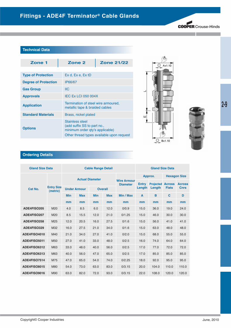
Gland Size Data Cable Range Detail Gland Size Data
Cat No. Entry Size(metric)
Actual Diameter Wire ArmourDiameter
Approx. Hexagon Size
EntryLength
ProjectedLength
AcrossFlats
AcrossCnrsUnder Armour Overall
Min Max Min Max Min / Max A B C D
mm mm mm mm mm mm mm mm mm
ADE4FISO205 M20 4.0 8.5 6.0 12.0 0/0.9 15.0 36.0 19.0 24.0
ADE4FISO207 M20 8.5 15.5 12.0 21.0 0/1.25 15.0 46.0 30.0 30.0
ADE4FISO258 M25 12.0 20.5 16.0 27.5 0/1.6 15.0 56.0 41.0 41.0
ADE4FISO329 M32 16.0 27.5 21.0 34.0 0/1.6 15.0 63.0 48.0 48.0
ADE4FISO4010 M40 21.0 34.0 27.0 41.0 0/2.0 15.0 68.0 55.0 55.0
ADE4FISO5011 M50 27.0 41.0 33.0 48.0 0/2.5 16.0 74.0 64.0 64.0
ADE4FISO6312 M63 33.0 48.0 40.0 56.0 0/2.5 17.0 77.0 72.0 72.0
ADE4FISO6313 M63 40.0 56.0 47.0 65.0 0/2.5 17.0 85.0 85.0 85.0
ADE4FISO7514 M75 47.0 65.0 54.0 74.0 0/2.25 18.0 92.0 95.0 95.0
ADE4FISO8015 M80 54.0 73.0 63.0 83.0 0/3.15 20.0 104.0 110.0 110.0
ADE4FISO9016 M90 63.0 82.0 72.0 93.0 0/3.15 22.0 108.0 120.0 120.0
Ordering Details
Type of Protection Ex d, Ex e, Ex tD
Degree of Protection IP66/67
Gas Group IIC
Approvals IEC Ex LCI 050 004X
Application Termination of steel wire armoured,metallic tape & braided cables
Standard Materials Brass, nickel plated
Options
Stainless steel(add suffix SS to part no.,minimum order qty’s applicable)Other thread types available upon request
Technical Data
Zone 1 Zone 2 Zone 21/22
Fittings - ADE4F Terminator® Cable Glands
2-9
Copyright© Cooper Industries June, 2010
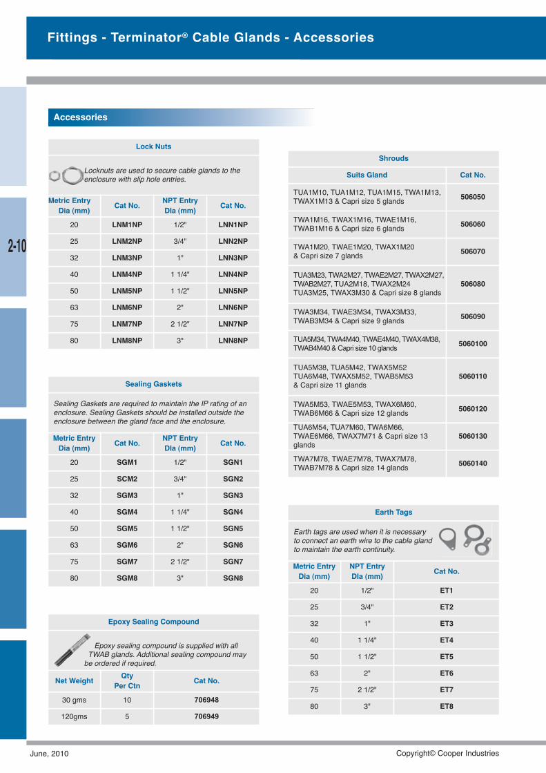
Epoxy Sealing Compound
Epoxy sealing compound is supplied with allTWAB glands. Additional sealing compound may
be ordered if required.
Net Weight QtyPer Ctn Cat No.
30 gms 10 706948
120gms 5 706949
Fittings - Terminator® Cable Glands - Accessories
Sealing Gaskets
Sealing Gaskets are required to maintain the IP rating of anenclosure. Sealing Gaskets should be installed outside theenclosure between the gland face and the enclosure.
Metric EntryDia (mm) Cat No. NPT Entry
DIa (mm) Cat No.
20 SGM1 1/2" SGN1
25 SCM2 3/4" SGN2
32 SGM3 1" SGN3
40 SGM4 1 1/4" SGN4
50 SGM5 1 1/2" SGN5
63 SGM6 2" SGN6
75 SGM7 2 1/2" SGN7
80 SGM8 3" SGN8
Lock Nuts
Locknuts are used to secure cable glands to theenclosure with slip hole entries.
Metric EntryDia (mm) Cat No. NPT Entry
DIa (mm) Cat No.
20 LNM1NP 1/2" LNN1NP
25 LNM2NP 3/4" LNN2NP
32 LNM3NP 1" LNN3NP
40 LNM4NP 1 1/4" LNN4NP
50 LNM5NP 1 1/2" LNN5NP
63 LNM6NP 2" LNN6NP
75 LNM7NP 2 1/2" LNN7NP
80 LNM8NP 3" LNN8NP
Accessories
Shrouds
Suits Gland Cat No.
TUA1M10, TUA1M12, TUA1M15, TWA1M13,TWAX1M13 & Capri size 5 glands 506050
TWA1M16, TWAX1M16, TWAE1M16,TWAB1M16 & Capri size 6 glands 506060
TWA1M20, TWAE1M20, TWAX1M20& Capri size 7 glands 506070
TUA3M23, TWA2M27, TWAE2M27, TWAX2M27,TWAB2M27, TUA2M18, TWAX2M24TUA3M25, TWAX3M30 & Capri size 8 glands
506080
TWA3M34, TWAE3M34, TWAX3M33,TWAB3M34 & Capri size 9 glands 506090
TUA5M34, TWA4M40, TWAE4M40, TWAX4M38,TWAB4M40&Capri size 10 glands 5060100
TUA5M38, TUA5M42, TWAX5M52TUA6M48, TWAX5M52, TWAB5M53& Capri size 11 glands
5060110
TWA5M53, TWAE5M53, TWAX6M60,TWAB6M66 & Capri size 12 glands 5060120
TUA6M54, TUA7M60, TWA6M66,TWAE6M66, TWAX7M71 & Capri size 13glands
5060130
TWA7M78, TWAE7M78, TWAX7M78,TWAB7M78 & Capri size 14 glands 5060140
Earth Tags
Earth tags are used when it is necessaryto connect an earth wire to the cable glandto maintain the earth continuity.
Metric EntryDia (mm)
NPT EntryDIa (mm) Cat No.
20 1/2" ET1
25 3/4" ET2
32 1" ET3
40 1 1/4" ET4
50 1 1/2" ET5
63 2" ET6
75 2 1/2" ET7
80 3" ET8
2-10
June, 2010 Copyright© Cooper Industries
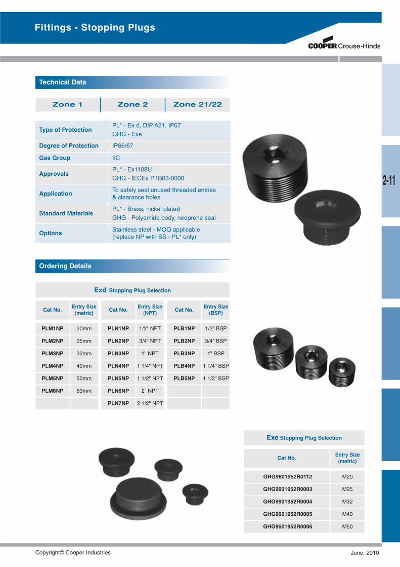
Type of Protection PL* - Ex d, DIP A21, IP67GHG - Exe
Degree of Protection IP66/67
Gas Group IIC
Approvals PL* - Ex1108UGHG - IECEx PTB03-0000
Application To safely seal unused threaded entries& clearance holes
Standard Materials PL* - Brass, nickel platedGHG - Polyamide body, neoprene seal
Options Stainless steel - MOQ applicable(replace NP with SS - PL* only)
Technical Data
Zone 1 Zone 2 Zone 21/22
Exd Stopping Plug Selection
Cat No. Entry Size(metric) Cat No. Entry Size
(NPT) Cat No. Entry Size(BSP)
PLM1NP 20mm PLN1NP 1/2" NPT PLB1NP 1/2" BSP
PLM2NP 25mm PLN2NP 3/4" NPT PLB2NP 3/4" BSP
PLM3NP 32mm PLN3NP 1" NPT PLB3NP 1" BSP
PLM4NP 40mm PLN4NP 1 1/4" NPT PLB4NP 1 1/4" BSP
PLM5NP 50mm PLN5NP 1 1/2" NPT PLB5NP 1 1/2" BSP
PLM6NP 63mm PLN6NP 2" NPT
PLN7NP 2 1/2" NPT
Ordering Details
Exe Stopping Plug Selection
Cat No. Entry Size(metric)
GHG9601952R0112 M20
GHG9601952R0003 M25
GHG9601952R0004 M32
GHG9601952R0005 M40
GHG9601952R0006 M50
2-11
Fittings - Stopping Plugs
Copyright© Cooper Industries June, 2010
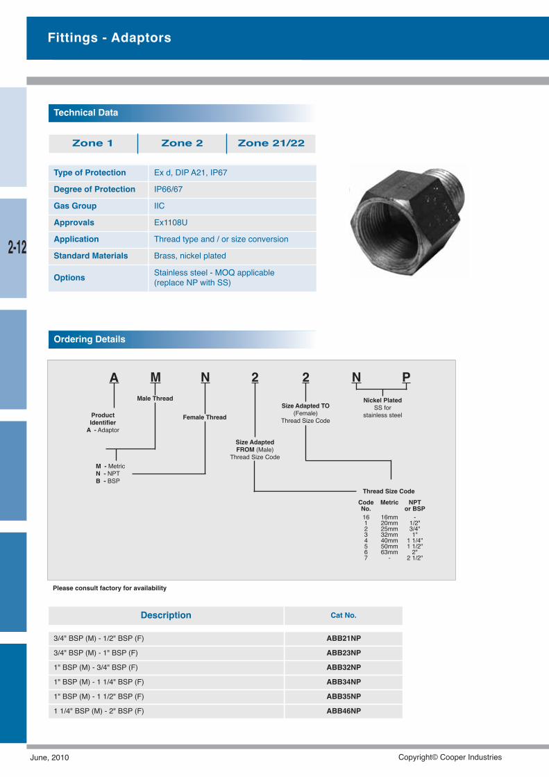
Type of Protection Ex d, DIP A21, IP67
Degree of Protection IP66/67
Gas Group IIC
Approvals Ex1108U
Application Thread type and / or size conversion
Standard Materials Brass, nickel plated
Options Stainless steel - MOQ applicable(replace NP with SS)
Technical Data
Zone 1 Zone 2 Zone 21/22
A M N 2
M - MetricN - NPTB - BSP
2Male Thread
Female Thread
Size AdaptedFROM (Male)
Thread Size Code
ProductIdentifierA - Adaptor
Size Adapted TO(Female)
Thread Size Code
Ordering Details
N PNickel Plated
SS forstainless steel
Thread Size CodeCode Metric NPTNo. or BSP16 16mm -1 20mm 1/2"2 25mm 3/4"3 32mm 1"4 40mm 1 1/4"5 50mm 1 1/2"6 63mm 2"7 - 2 1/2"
Fittings - Adaptors
Please consult factory for availability
Description Cat No.
3/4" BSP (M) - 1/2" BSP (F) ABB21NP
3/4" BSP (M) - 1" BSP (F) ABB23NP
1" BSP (M) - 3/4" BSP (F) ABB32NP
1" BSP (M) - 1 1/4" BSP (F) ABB34NP
1" BSP (M) - 1 1/2" BSP (F) ABB35NP
1 1/4" BSP (M) - 2" BSP (F) ABB46NP
2-12
June, 2010 Copyright© Cooper Industries
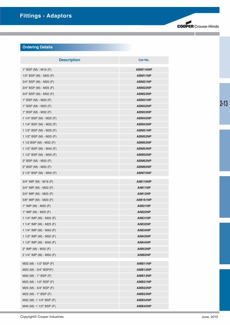
1" BSP (M) - M16 (F) ABM116NP
1/2" BSP (M) - M20 (F) ABM11NP
3/4" BSP (M) - M20 (F) ABM21NP
3/4" BSP (M) - M25 (F) ABM22NP
3/4" BSP (M) - M32 (F) ABM23NP
1" BSP (M) - M20 (F) ABM31NP
1" BSP (M) - M25 (F) ABM32NP
1" BSP (M) - M32 (F) ABM33NP
1 1/4" BSP (M) - M25 (F) ABM42NP
1 1/4" BSP (M) - M32 (F) ABM43NP
1 1/2" BSP (M) - M20 (F) ABM51NP
1 1/2" BSP (M) - M25 (F) ABM52NP
1 1/2 BSP (M) - M32 (F) ABM53NP
1 1/2" BSP (M) - M40 (F) ABM54NP
1 1/2" BSP (M) - M50 (F) ABM55NP
2" BSP (M) - M32 (F) ABM63NP
2" BSP (M) - M50 (F) ABM65NP
2 1/2" BSP (M) - M50 (F) ABM75NP
3/4" IMP (M) - M16 (F) AIM116NP
3/4" IMP (M) - M20 (F) AIM11NP
3/4" IMP (M) - M25 (F) AIM12NP
5/8" IMP (M) - M20 (F) AIM161NP
1" IMP (M) - M20 (F) AIM21NP
1" IMP (M) - M25 (F) AIM22NP
1 1/4" IMP (M) - M20 (F) AIM31NP
1 1/4" IMP (M) - M25 (F) AIM32NP
1 1/4" IMP (M) - M40 (F) AIM34NP
1 1/2" IMP (M) - M32 (F) AIM43NP
1 1/2" IMP (M) - M40 (F) AIM44NP
Ordering Details
2" IMP (M) - M32 (F) AIM53NP
2 1/4" IMP (M) - M50 (F) AIM65NP
Description Cat No.
M20 (M) - 1/2" BSP (F) AMB11NP
M20 (M) - 3/4" BSP(F) AMB12NP
M20 (M) - 1" BSP (F) AMB13NP
M25 (M) - 1/2" BSP (F) AMB21NP
M25 (M) - 3/4" BSP (F) AMB22NP
M25 (M) - 1" BSP (F) AMB23NP
M32 (M)- 1 1/4" BSP (F) AMB34NP
M40 (M)- 1 1/2" BSP (F) AMB45NP
Fittings - Adaptors
2-13
Copyright© Cooper Industries June, 2010
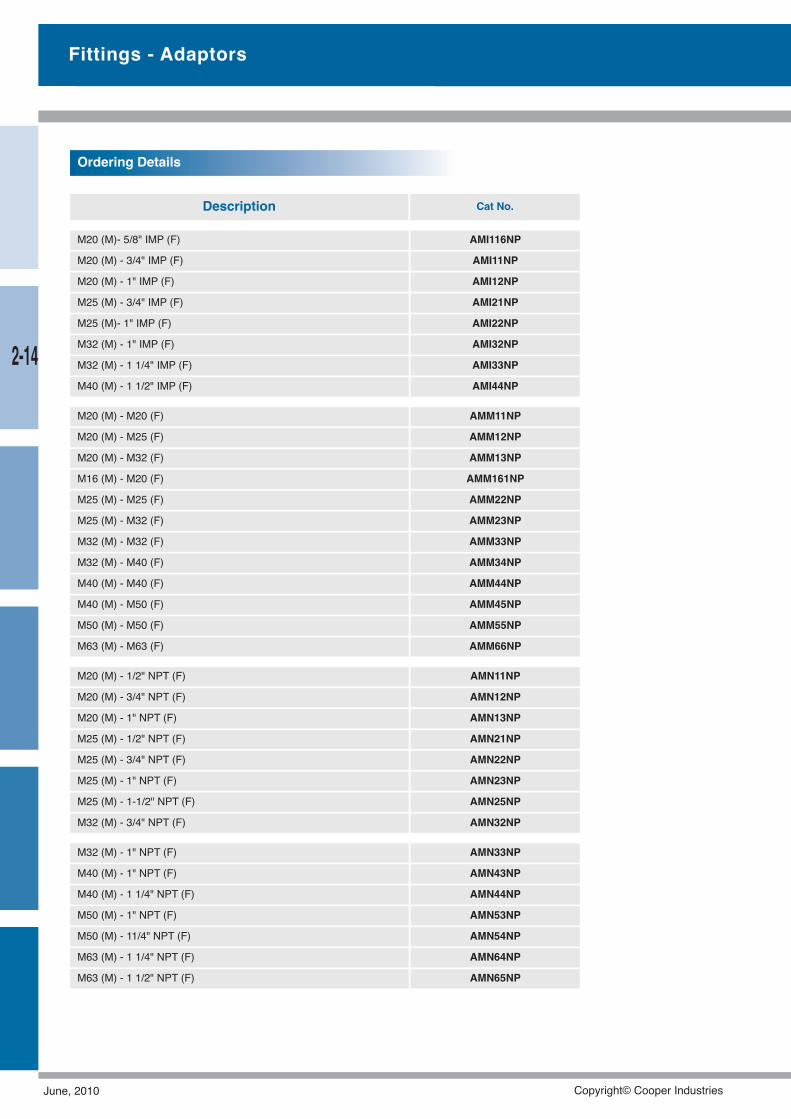
M20 (M)- 5/8" IMP (F) AMI116NP
M20 (M) - 3/4" IMP (F) AMI11NP
M20 (M) - 1" IMP (F) AMI12NP
M25 (M) - 3/4" IMP (F) AMI21NP
M25 (M)- 1" IMP (F) AMI22NP
M32 (M) - 1" IMP (F) AMI32NP
M32 (M) - 1 1/4" IMP (F) AMI33NP
M40 (M) - 1 1/2" IMP (F) AMI44NP
M20 (M) - M20 (F) AMM11NP
M20 (M) - M25 (F) AMM12NP
M20 (M) - M32 (F) AMM13NP
M16 (M) - M20 (F) AMM161NP
M25 (M) - M25 (F) AMM22NP
M25 (M) - M32 (F) AMM23NP
M32 (M) - M32 (F) AMM33NP
M32 (M) - M40 (F) AMM34NP
M40 (M) - M40 (F) AMM44NP
M40 (M) - M50 (F) AMM45NP
M50 (M) - M50 (F) AMM55NP
M63 (M) - M63 (F) AMM66NP
Ordering Details
M20 (M) - 1/2" NPT (F) AMN11NP
M20 (M) - 3/4" NPT (F) AMN12NP
M20 (M) - 1" NPT (F) AMN13NP
M25 (M) - 1/2" NPT (F) AMN21NP
M25 (M) - 3/4" NPT (F) AMN22NP
M25 (M) - 1" NPT (F) AMN23NP
M25 (M) - 1-1/2" NPT (F) AMN25NP
M32 (M) - 3/4" NPT (F) AMN32NP
M32 (M) - 1" NPT (F) AMN33NP
M40 (M) - 1" NPT (F) AMN43NP
M40 (M) - 1 1/4" NPT (F) AMN44NP
M50 (M) - 1" NPT (F) AMN53NP
M50 (M) - 11/4" NPT (F) AMN54NP
M63 (M) - 1 1/4" NPT (F) AMN64NP
M63 (M) - 1 1/2" NPT (F) AMN65NP
Description Cat No.
Fittings - Adaptors
2-14
June, 2010 Copyright© Cooper Industries
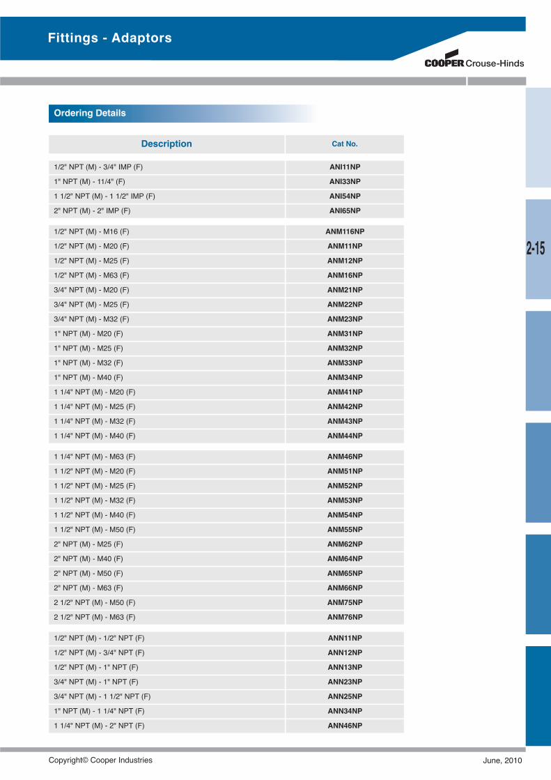
Ordering Details
1/2" NPT (M) - 3/4" IMP (F) ANI11NP
1" NPT (M) - 11/4" (F) ANI33NP
1 1/2" NPT (M) - 1 1/2" IMP (F) ANI54NP
2" NPT (M) - 2" IMP (F) ANI65NP
1/2" NPT (M) - M16 (F) ANM116NP
1/2" NPT (M) - M20 (F) ANM11NP
1/2" NPT (M) - M25 (F) ANM12NP
1/2" NPT (M) - M63 (F) ANM16NP
3/4" NPT (M) - M20 (F) ANM21NP
3/4" NPT (M) - M25 (F) ANM22NP
3/4" NPT (M) - M32 (F) ANM23NP
1" NPT (M) - M20 (F) ANM31NP
1" NPT (M) - M25 (F) ANM32NP
1" NPT (M) - M32 (F) ANM33NP
1" NPT (M) - M40 (F) ANM34NP
1 1/4" NPT (M) - M20 (F) ANM41NP
1 1/4" NPT (M) - M25 (F) ANM42NP
1 1/4" NPT (M) - M32 (F) ANM43NP
1 1/4" NPT (M) - M40 (F) ANM44NP
1 1/4" NPT (M) - M63 (F) ANM46NP
1 1/2" NPT (M) - M20 (F) ANM51NP
1 1/2" NPT (M) - M25 (F) ANM52NP
1 1/2" NPT (M) - M32 (F) ANM53NP
1 1/2" NPT (M) - M40 (F) ANM54NP
1 1/2" NPT (M) - M50 (F) ANM55NP
2" NPT (M) - M25 (F) ANM62NP
2" NPT (M) - M40 (F) ANM64NP
2" NPT (M) - M50 (F) ANM65NP
2" NPT (M) - M63 (F) ANM66NP
2 1/2" NPT (M) - M50 (F) ANM75NP
2 1/2" NPT (M) - M63 (F) ANM76NP
Description Cat No.
1/2" NPT (M) - 1/2" NPT (F) ANN11NP
1/2" NPT (M) - 3/4" NPT (F) ANN12NP
1/2" NPT (M) - 1" NPT (F) ANN13NP
3/4" NPT (M) - 1" NPT (F) ANN23NP
3/4" NPT (M) - 1 1/2" NPT (F) ANN25NP
1" NPT (M) - 1 1/4" NPT (F) ANN34NP
1 1/4" NPT (M) - 2" NPT (F) ANN46NP
Fittings - Adaptors
2-15
Copyright© Cooper Industries June, 2010
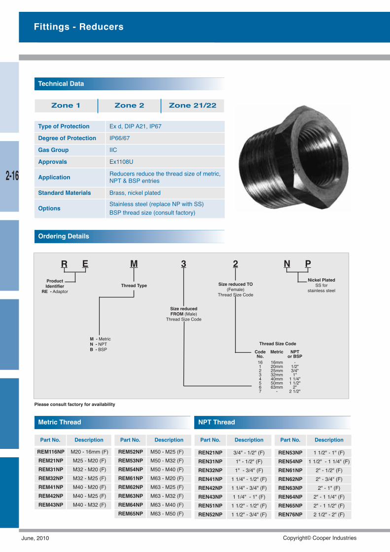
Type of Protection Ex d, DIP A21, IP67
Degree of Protection IP66/67
Gas Group IIC
Approvals Ex1108U
Application Reducers reduce the thread size of metric,NPT & BSP entries
Standard Materials Brass, nickel plated
Options Stainless steel (replace NP with SS)BSP thread size (consult factory)
Technical Data
Zone 1 Zone 2 Zone 21/22
Ordering Details
R E M 3
M - MetricN - NPTB - BSP
2
Thread Type
Size reducedFROM (Male)
Thread Size Code
ProductIdentifier
RE - AdaptorSize reduced TO
(Female)Thread Size Code
N PNickel Plated
SS forstainless steel
Thread Size Code
Code Metric NPTNo. or BSP16 16mm -1 20mm 1/2"2 25mm 3/4"3 32mm 1"4 40mm 1 1/4"5 50mm 1 1/2"6 63mm 2"7 - 2 1/2"
REN21NP 3/4" - 1/2" (F)REN31NP 1" - 1/2" (F)REN32NP 1" - 3/4" (F)REN41NP 1 1/4" - 1/2" (F)REN42NP 1 1/4" - 3/4" (F)REN43NP 1 1/4" - 1" (F)REN51NP 1 1/2" - 1/2" (F)REN52NP 1 1/2" - 3/4" (F)
Part No. Description
REM116NP M20 - 16mm (F)REM21NP M25 - M20 (F)REM31NP M32 - M20 (F)REM32NP M32 - M25 (F)REM41NP M40 - M20 (F)REM42NP M40 - M25 (F)REM43NP M40 - M32 (F)
Part No. Description
REN53NP 1 1/2" - 1" (F)REN54NP 1 1/2" - 1 1/4" (F)REN61NP 2" - 1/2" (F)REN62NP 2" - 3/4" (F)REN63NP 2" - 1" (F)REN64NP 2" - 1 1/4" (F)REN65NP 2" - 1 1/2" (F)REN76NP 2 1/2" - 2" (F)
Part No. Description
Fittings - Reducers
Please consult factory for availability
REM52NP M50 - M25 (F)REM53NP M50 - M32 (F)REM54NP M50 - M40 (F)REM61NP M63 - M20 (F)REM62NP M63 - M25 (F)REM63NP M63 - M32 (F)REM64NP M63 - M40 (F)REM65NP M63 - M50 (F)
Metric Thread
Part No. Description
NPT Thread
2-16
June, 2010 Copyright© Cooper Industries
Code Metric NPTNo. or BSP16 16mm -1 20mm 1/2"2 25mm 3/4"3 32mm 1"4 40mm 1 1/4"5 50mm 1 1/2"6 63mm 2"7 - 2 1/2"
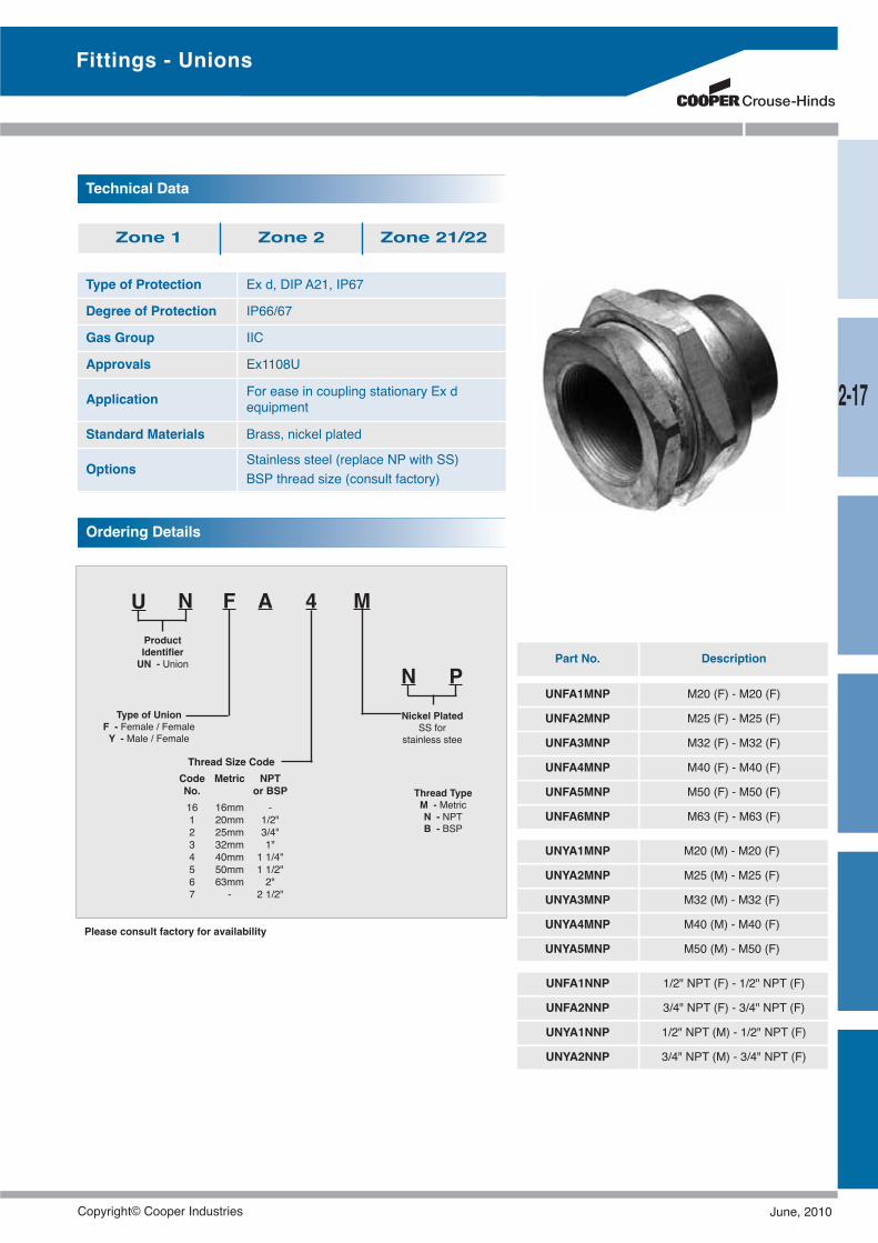
Type of Protection Ex d, DIP A21, IP67
Degree of Protection IP66/67
Gas Group IIC
Approvals Ex1108U
Application For ease in coupling stationary Ex dequipment
Standard Materials Brass, nickel plated
Options Stainless steel (replace NP with SS)BSP thread size (consult factory)
Technical Data
Zone 1 Zone 2 Zone 21/22
Ordering Details
U N F A 4ProductIdentifierUN - Union
M
NNickel Plated
SS forstainless stee
Type of UnionF - Female / FemaleY - Male / Female
P
Thread TypeM - MetricN - NPTB - BSP
Thread Size Code
UNFA1MNP M20 (F) - M20 (F)
UNFA2MNP M25 (F) - M25 (F)
UNFA3MNP M32 (F) - M32 (F)
UNFA4MNP M40 (F) - M40 (F)
UNFA5MNP M50 (F) - M50 (F)
UNFA6MNP M63 (F) - M63 (F)
UNFA1NNP 1/2" NPT (F) - 1/2" NPT (F)
UNFA2NNP 3/4" NPT (F) - 3/4" NPT (F)
UNYA1NNP 1/2" NPT (M) - 1/2" NPT (F)
UNYA2NNP 3/4" NPT (M) - 3/4" NPT (F)
UNYA1MNP M20 (M) - M20 (F)
UNYA2MNP M25 (M) - M25 (F)
UNYA3MNP M32 (M) - M32 (F)
UNYA4MNP M40 (M) - M40 (F)
UNYA5MNP M50 (M) - M50 (F)
Part No. Description
Please consult factory for availability
Fittings - Unions
2-17
Copyright© Cooper Industries June, 2010
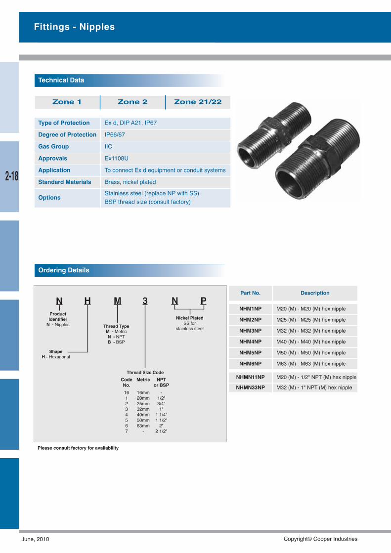
Fittings - Nipples
Type of Protection Ex d, DIP A21, IP67
Degree of Protection IP66/67
Gas Group IIC
Approvals Ex1108U
Application To connect Ex d equipment or conduit systems
Standard Materials Brass, nickel plated
Options Stainless steel (replace NP with SS)BSP thread size (consult factory)
Technical Data
Zone 1 Zone 2 Zone 21/22
N H M 3ProductIdentifierN - Nipples
NNickel Plated
SS forstainless steel
ShapeH - Hexagonal
P
Thread TypeM - MetricN - NPTB - BSP
Ordering Details
Thread Size CodeCode Metric NPTNo. or BSP16 16mm -1 20mm 1/2"2 25mm 3/4"3 32mm 1"4 40mm 1 1/4"5 50mm 1 1/2"6 63mm 2"7 - 2 1/2"
Part No. Description
Please consult factory for availability
NHM1NP M20 (M) - M20 (M) hex nipple
NHM2NP M25 (M) - M25 (M) hex nipple
NHM3NP M32 (M) - M32 (M) hex nipple
NHM4NP M40 (M) - M40 (M) hex nipple
NHM5NP M50 (M) - M50 (M) hex nipple
NHM6NP M63 (M) - M63 (M) hex nipple
NHMN11NP M20 (M) - 1/2" NPT (M) hex nipple
NHMN33NP M32 (M) - 1" NPT (M) hex nipple
2-18
June, 2010 Copyright© Cooper Industries
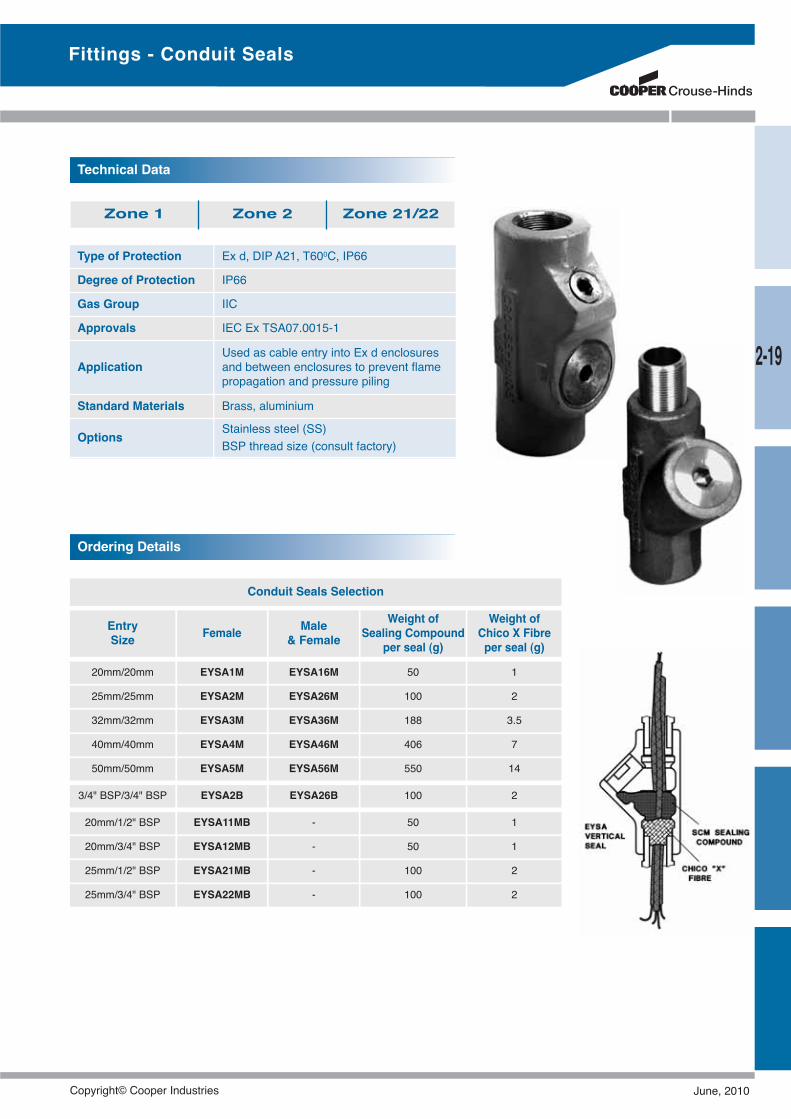
Type of Protection Ex d, DIP A21, T600C, IP66
Degree of Protection IP66
Gas Group IIC
Approvals IEC Ex TSA07.0015-1
ApplicationUsed as cable entry into Ex d enclosuresand between enclosures to prevent flamepropagation and pressure piling
Standard Materials Brass, aluminium
Options Stainless steel (SS)BSP thread size (consult factory)
Technical Data
Zone 1 Zone 2 Zone 21/22
Conduit Seals Selection
EntrySize Female Male
& FemaleWeight of
Sealing Compoundper seal (g)
Weight ofChico X Fibreper seal (g)
20mm/20mm EYSA1M EYSA16M 50 1
25mm/25mm EYSA2M EYSA26M 100 2
32mm/32mm EYSA3M EYSA36M 188 3.5
40mm/40mm EYSA4M EYSA46M 406 7
50mm/50mm EYSA5M EYSA56M 550 14
3/4" BSP/3/4" BSP EYSA2B EYSA26B 100 2
20mm/1/2" BSP EYSA11MB - 50 1
20mm/3/4" BSP EYSA12MB - 50 1
25mm/1/2" BSP EYSA21MB - 100 2
25mm/3/4" BSP EYSA22MB - 100 2
Ordering Details
Fittings - Conduit Seals
2-19
Copyright© Cooper Industries June, 2010
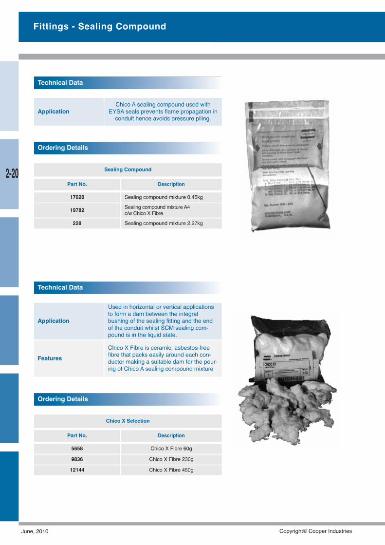
ApplicationChico A sealing compound used with
EYSA seals prevents flame propagation inconduit hence avoids pressure piling.
Technical Data
Application
Used in horizontal or vertical applicationsto form a dam between the integralbushing of the sealing fitting and the endof the conduit whilst SCM sealing com-pound is in the liquid state.
FeaturesChico X Fibre is ceramic, asbestos-freefibre that packs easily around each con-ductor making a suitable dam for the pour-ing of Chico A sealing compound mixture
Technical Data
Chico X Selection
Part No. Description
5658 Chico X Fibre 60g
9836 Chico X Fibre 230g
12144 Chico X Fibre 450g
Ordering Details
Fittings - Sealing Compound
Sealing Compound
Part No. Description
17620 Sealing compound mixture 0.45kg
19782 Sealing compound mixture A4c/w Chico X Fibre
228 Sealing compound mixture 2.27kg
Ordering Details
2-20
June, 2010 Copyright© Cooper Industries
Type of Protection Ex d, DIP A21, IP67
Degree of Protection IP67
Gas Group IIB
Approvals Ex1108U
Application
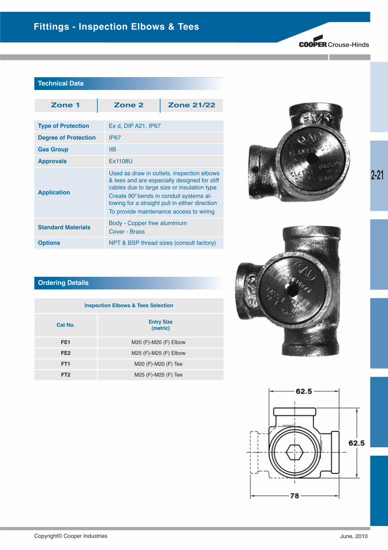
Used as draw in outlets, inspection elbows& tees and are especially designed for stiffcables due to large size or insulation typeCreate 900 bends in conduit systems al-lowing for a straight pull in either directionTo provide maintenance access to wiring
Standard Materials Body - Copper free aluminiumCover - Brass
Options NPT & BSP thread sizes (consult factory)
Technical Data
Zone 1 Zone 2 Zone 21/22
Inspection Elbows & Tees Selection
Cat No. Entry Size(metric)
FE1 M20 (F)-M20 (F) Elbow
FE2 M25 (F)-M25 (F) Elbow
FT1 M20 (F)-M20 (F) Tee
FT2 M25 (F)-M25 (F) Tee
Ordering Details
Fittings - Inspection Elbows & Tees
2-21
Copyright© Cooper Industries June, 2010
Junction Boxes
Using correct termination boxes for the task at hand saves costand time.From a small FRP Junction Box to a large Stainless steel mar-shalling box, Crouse-Hinds has the solution.Our local Australian JBE stainless steel design is now compli-mented by our UK designed, dual IECEx and ATEX certifiedEx-cell and STB ranges.These boxes are custom built and engineered to yourspecific requirement, ensuring the right product for your appli-cation
June, 2010 Copyright© Cooper Industries
3-1
Junction Boxes
Junction BoxesGUA - Exd ........................................................................3-2C30 & C31 - Ex d, Ex tD A21 IP67 T850C ......................3-3PBEC - Exe, Ex tD A21, T800C ......................................3-5GUBA - Exd ....................................................................3-6EJBA - Exd ......................................................................3-7EJB - Exd ........................................................................3-8JBEC - Exe......................................................................3-9JBDC - Combustible Dust ..............................................3-9JBWC - Weatherproof ....................................................3-9JBE - Increased Safety..................................................3-10JBD - Combustible Dust ................................................3-10JBI - Intrinsically Safe....................................................3-10JBW - Weatherproof......................................................3-10XLH - Ex e ia, Ex dem ia/ib, Ex td ................................3-12PBE - Ex e ....................................................................3-13
Copyright© Cooper Industries June, 2010
3-2
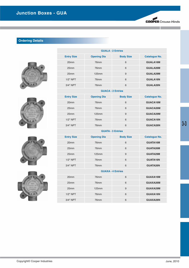
Junction Boxes - GUA
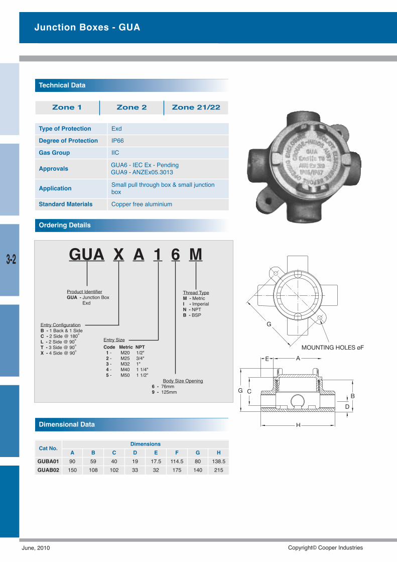
Type of Protection Exd
Degree of Protection IP66
Gas Group IIC
Approvals GUA6 - IEC Ex - PendingGUA9 - ANZEx05.3013
Application Small pull through box & small junctionbox
Standard Materials Copper free aluminium
Technical Data
Zone 1 Zone 2 Zone 21/22
Dimensional Data
Cat No.Dimensions
A B C D E F G HGUBA01 90 59 40 19 17.5 114.5 80 138.5GUAB02 150 108 102 33 32 175 140 215
GUA X A 1 6 M
Body Size Opening6 - 76mm9 - 125mm
Thread TypeM - MetricI - ImperialN - NPTB - BSP
Product IdentifierGUA - Junction Box
Exd
Entry ConfigurationB - 1 Back & 1 SideC - 2 Side @ 180oL - 2 Side @ 90oT - 3 Side @ 90oX - 4 Side @ 90o
Entry SizeCode Metric NPT1 - M20 1/2"2 - M25 3/4"3 - M32 1"4 - M40 1 1/4"5 - M50 1 1/2"
Ordering Details
June, 2010 Copyright© Cooper Industries
3-3
Junction Boxes - GUA
Ordering Details
GUALA - 2 Entries
Entry Size Opening Dia Body Size Catalogue No.
20mm 76mm 6 GUALA16M
25mm 76mm 6 GUALA26M
25mm 125mm 9 GUALA29M
1/2" NPT 76mm 6 GUALA16N
3/4" NPT 76mm 6 GUALA26N
GUACA - 2 Entries
Entry Size Opening Dia Body Size Catalogue No.
20mm 76mm 6 GUACA16M
25mm 76mm 6 GUACA26M
25mm 125mm 9 GUACA29M
1/2" NPT 76mm 6 GUACA16N
3/4" NPT 76mm 6 GUACA26N
GUATA - 3 Entries
Entry Size Opening Dia Body Size Catalogue No.
20mm 76mm 6 GUATA16M
25mm 76mm 6 GUATA26M
25mm 125mm 9 GUATA29M
1/2" NPT 76mm 6 GUATA16N
3/4" NPT 76mm 6 GUATA26N
GUAXA - 4 Entries
20mm 76mm 6 GUAXA16M
25mm 76mm 6 GUAXA26M
25mm 125mm 9 GUAXA29M
1/2" NPT 76mm 6 GUAXA16N
3/4" NPT 76mm 6 GUAXA26N
Copyright© Cooper Industries June, 2010
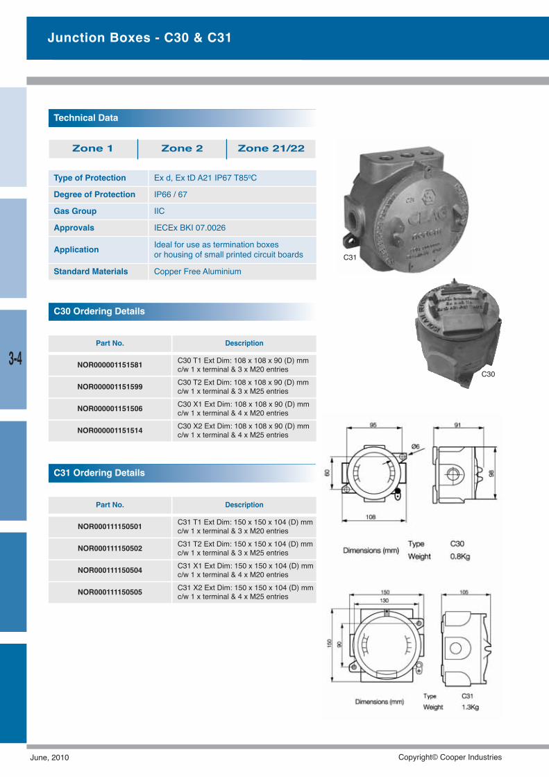
Type of Protection Ex d, Ex tD A21 IP67 T850C
Degree of Protection IP66 / 67
Gas Group IIC
Approvals IECEx BKI 07.0026
Application Ideal for use as termination boxesor housing of small printed circuit boards
Standard Materials Copper Free Aluminium
Technical Data
Zone 1 Zone 2 Zone 21/22
Junction Boxes - C30 & C31
Part No. Description
NOR000001151581 C30 T1 Ext Dim: 108 x 108 x 90 (D) mmc/w 1 x terminal & 3 x M20 entries
NOR000001151599 C30 T2 Ext Dim: 108 x 108 x 90 (D) mmc/w 1 x terminal & 3 x M25 entries
NOR000001151506 C30 X1 Ext Dim: 108 x 108 x 90 (D) mmc/w 1 x terminal & 4 x M20 entries
NOR000001151514 C30 X2 Ext Dim: 108 x 108 x 90 (D) mmc/w 1 x terminal & 4 x M25 entries
C30 Ordering Details
Part No. Description
NOR000111150501 C31 T1 Ext Dim: 150 x 150 x 104 (D) mmc/w 1 x terminal & 3 x M20 entries
NOR000111150502 C31 T2 Ext Dim: 150 x 150 x 104 (D) mmc/w 1 x terminal & 3 x M25 entries
NOR000111150504 C31 X1 Ext Dim: 150 x 150 x 104 (D) mmc/w 1 x terminal & 4 x M20 entries
NOR000111150505 C31 X2 Ext Dim: 150 x 150 x 104 (D) mmc/w 1 x terminal & 4 x M25 entries
C31 Ordering Details
C31
C303-4
June, 2010 Copyright© Cooper Industries
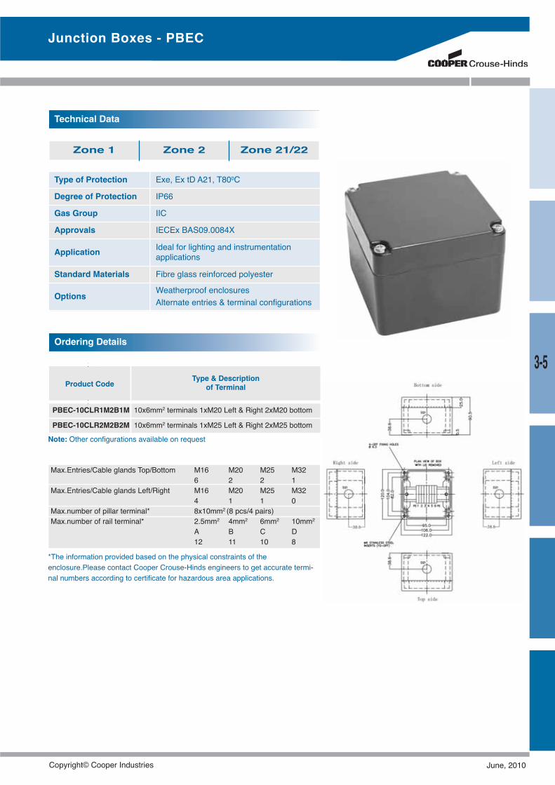
Product CodeType & Description
of Terminal
PBEC-10CLR1M2B1M 10x6mm2 terminals 1xM20 Left & Right 2xM20 bottom
PBEC-10CLR2M2B2M 10x6mm2 terminals 1xM25 Left & Right 2xM25 bottom
Type of Protection Exe, Ex tD A21, T800C
Degree of Protection IP66
Gas Group IIC
Approvals IECEx BAS09.0084X
Application Ideal for lighting and instrumentationapplications
Standard Materials Fibre glass reinforced polyester
Options Weatherproof enclosuresAlternate entries & terminal configurations
Technical Data
Zone 1 Zone 2 Zone 21/22
Ordering Details
Note: Other configurations available on request
Junction Boxes - PBEC
3-5
Max.Entries/Cable glands Top/Bottom M16 M20 M25 M326 2 2 1
Max.Entries/Cable glands Left/Right M16 M20 M25 M324 1 1 0
Max.number of pillar terminal* 8x10mm2 (8 pcs/4 pairs)Max.number of rail terminal* 2.5mm2 4mm2 6mm2 10mm2
A B C D12 11 10 8
*The information provided based on the physical constraints of theenclosure.Please contact Cooper Crouse-Hinds engineers to get accurate termi-nal numbers according to certificate for hazardous area applications.
Copyright© Cooper Industries June, 2010
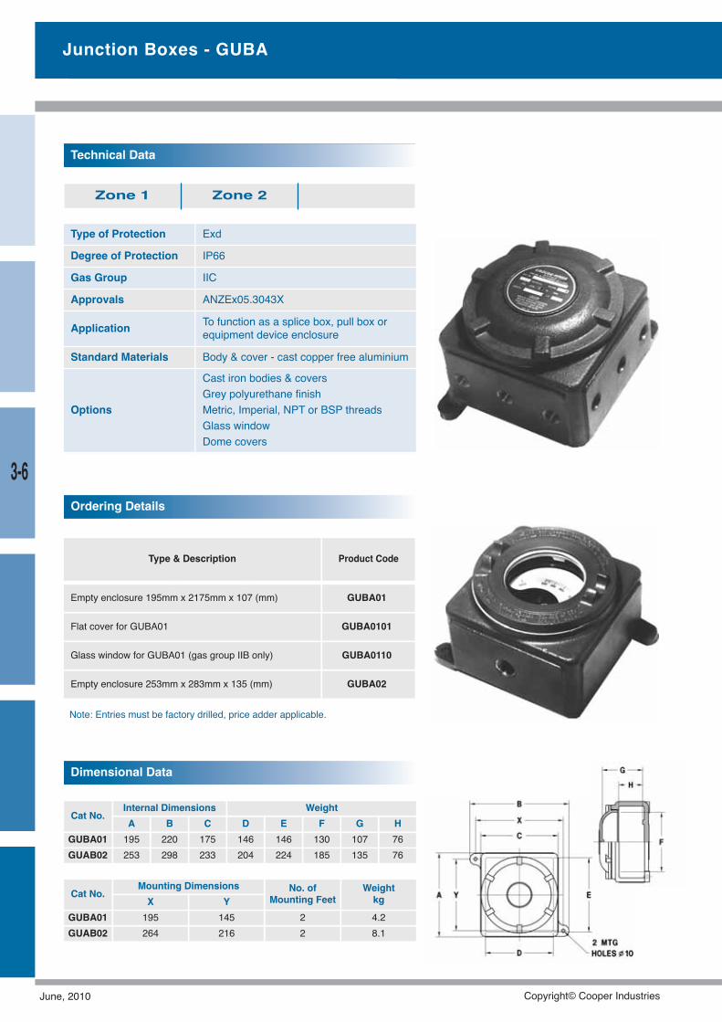
Type of Protection Exd
Degree of Protection IP66
Gas Group IIC
Approvals ANZEx05.3043X
Application To function as a splice box, pull box orequipment device enclosure
Standard Materials Body & cover - cast copper free aluminium
Options
Cast iron bodies & coversGrey polyurethane finishMetric, Imperial, NPT or BSP threadsGlass windowDome covers
Technical Data
Zone 1 Zone 2
Dimensional Data
Type & Description Product Code
Empty enclosure 195mm x 2175mm x 107 (mm) GUBA01
Flat cover for GUBA01 GUBA0101
Glass window for GUBA01 (gas group IIB only) GUBA0110
Empty enclosure 253mm x 283mm x 135 (mm) GUBA02
Ordering Details
Note: Entries must be factory drilled, price adder applicable.
Cat No.Internal Dimensions WeightA B C D E F G H
GUBA01 195 220 175 146 146 130 107 76GUAB02 253 298 233 204 224 185 135 76
Cat No.Mounting Dimensions No. of
Mounting FeetWeightkgX Y
GUBA01 195 145 2 4.2GUAB02 264 216 2 8.1
Junction Boxes - GUBA
3-6
June, 2010 Copyright© Cooper Industries
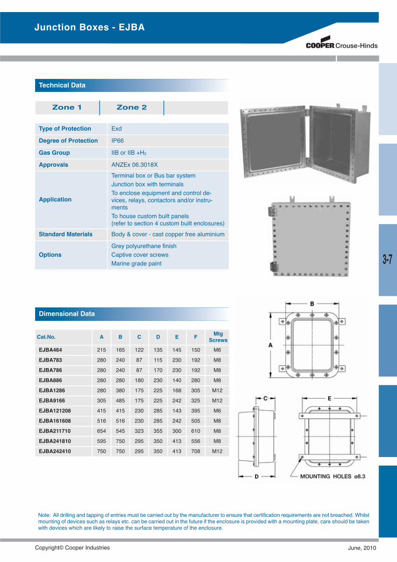
Dimensional Data
Cat.No. A B C D E F MtgScrews
EJBA464 215 165 122 135 145 150 M6
EJBA783 280 240 87 115 230 192 M8
EJBA786 280 240 87 170 230 192 M8
EJBA886 280 280 180 230 140 280 M8
EJBA1286 280 380 175 225 168 305 M12
EJBA9166 305 485 175 225 242 325 M12
EJBA121208 415 415 230 285 143 395 M6
EJBA161608 516 516 230 285 242 505 M8
EJBA211710 654 545 323 355 300 610 M8
EJBA241810 595 750 295 350 413 556 M8
EJBA242410 750 750 295 350 413 708 M12
Type of Protection Exd
Degree of Protection IP66
Gas Group IIB or IIB +H2
Approvals ANZEx 06.3018X
Application
Terminal box or Bus bar systemJunction box with terminalsTo enclose equipment and control de-vices, relays, contactors and/or instru-mentsTo house custom built panels(refer to section 4 custom built enclosures)
Standard Materials Body & cover - cast copper free aluminium
OptionsGrey polyurethane finishCaptive cover screwsMarine grade paint
Technical Data
Zone 1 Zone 2
Note: All drilling and tapping of entries must be carried out by the manufacturer to ensure that certification requirements are not breached. Whilstmounting of devices such as relays etc. can be carried out in the future if the enclosure is provided with a mounting plate, care should be takenwith devices which are likely to raise the surface temperature of the enclosure.
Junction Boxes - EJBA
3-7
Copyright© Cooper Industries June, 2010
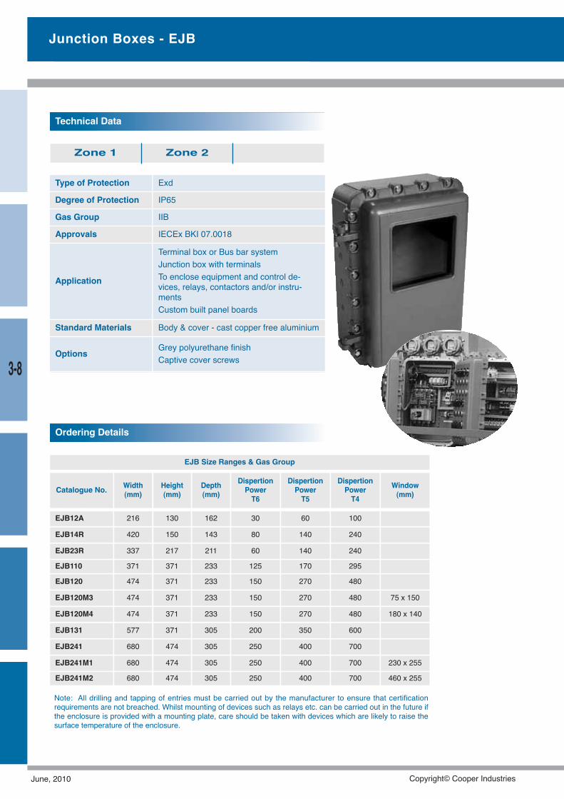
Junction Boxes - EJB
Type of Protection Exd
Degree of Protection IP65
Gas Group IIB
Approvals IECEx BKI 07.0018
Application
Terminal box or Bus bar systemJunction box with terminalsTo enclose equipment and control de-vices, relays, contactors and/or instru-mentsCustom built panel boards
Standard Materials Body & cover - cast copper free aluminium
Options Grey polyurethane finishCaptive cover screws
Technical Data
Zone 1 Zone 2
Ordering Details
Note: All drilling and tapping of entries must be carried out by the manufacturer to ensure that certificationrequirements are not breached. Whilst mounting of devices such as relays etc. can be carried out in the future ifthe enclosure is provided with a mounting plate, care should be taken with devices which are likely to raise thesurface temperature of the enclosure.
EJB Size Ranges & Gas Group
Catalogue No. Width(mm)
Height(mm)
Depth(mm)
DispertionPowerT6
DispertionPowerT5
DispertionPowerT4
Window(mm)
EJB12A 216 130 162 30 60 100
EJB14R 420 150 143 80 140 240
EJB23R 337 217 211 60 140 240
EJB110 371 371 233 125 170 295
EJB120 474 371 233 150 270 480
EJB120M3 474 371 233 150 270 480 75 x 150
EJB120M4 474 371 233 150 270 480 180 x 140
EJB131 577 371 305 200 350 600
EJB241 680 474 305 250 400 700
EJB241M1 680 474 305 250 400 700 230 x 255
EJB241M2 680 474 305 250 400 700 460 x 255
3-8
June, 2010 Copyright© Cooper Industries
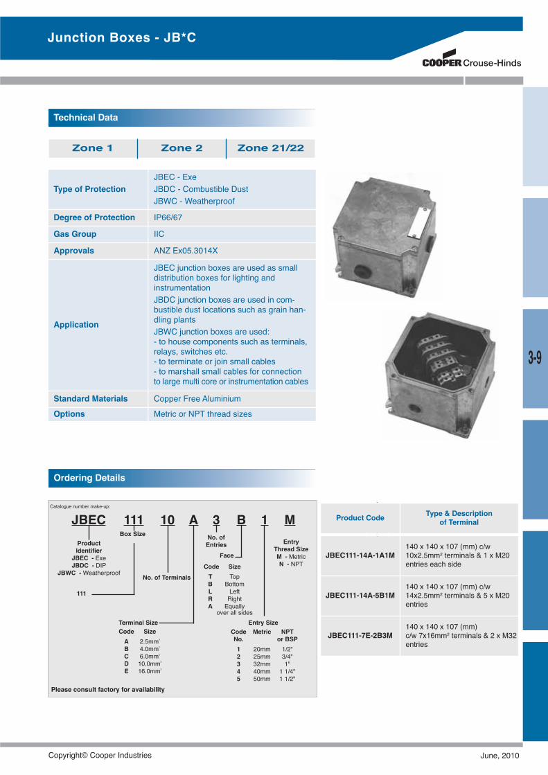
Type of ProtectionJBEC - ExeJBDC - Combustible DustJBWC - Weatherproof
Degree of Protection IP66/67
Gas Group IIC
Approvals ANZ Ex05.3014X
Application
JBEC junction boxes are used as smalldistribution boxes for lighting andinstrumentationJBDC junction boxes are used in com-bustible dust locations such as grain han-dling plantsJBWC junction boxes are used:- to house components such as terminals,relays, switches etc.- to terminate or join small cables- to marshall small cables for connectionto large multi core or instrumentation cables
Standard Materials Copper Free Aluminium
Options Metric or NPT thread sizes
Technical Data
Zone 1 Zone 2 Zone 21/22
Ordering Details
Catalogue number make-up:
JBEC 111 10
111
ABox Size
No. of Terminals
ProductIdentifier
JBEC - ExeJBDC - DIP
JBWC -Weatherproof
3 B
Entry SizeCode Metric NPTNo. or BSP1 20mm 1/2"2 25mm 3/4"3 32mm 1"4 40mm 1 1/4"5 50mm 1 1/2"
1 M
Terminal SizeCode SizeA 2.5mm2
B 4.0mm2
C 6.0mm2
D 10.0mm2
E 16.0mm2
FaceCode SizeT TopB BottomL LeftR RightA Equallyover all sides
No. ofEntries Entry
Thread SizeM - MetricN - NPT
Junction Boxes - JB*C
Please consult factory for availability
Product Code Type & Descriptionof Terminal
JBEC111-14A-1A1M140 x 140 x 107 (mm) c/w10x2.5mm2 terminals & 1 x M20entries each side
JBEC111-14A-5B1M140 x 140 x 107 (mm) c/w14x2.5mm2 terminals & 5 x M20entries
JBEC111-7E-2B3M140 x 140 x 107 (mm)c/w 7x16mm2 terminals & 2 x M32entries
3-9
Copyright© Cooper Industries June, 2010
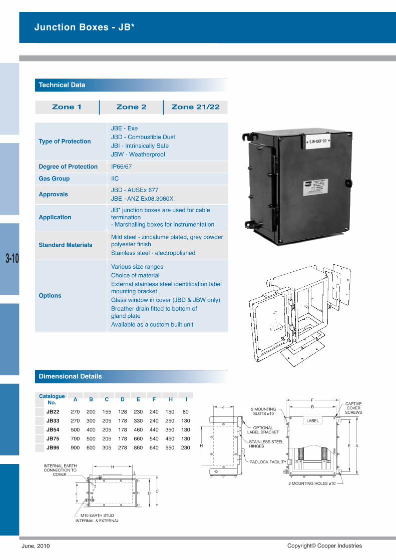
Type of Protection
JBE - ExeJBD - Combustible DustJBI - Intrinsically SafeJBW - Weatherproof
Degree of Protection IP66/67
Gas Group IIC
Approvals JBD - AUSEx 677JBE - ANZ Ex08.3060X
ApplicationJB* junction boxes are used for cabletermination- Marshalling boxes for instrumentation
Standard MaterialsMild steel - zincalume plated, grey powderpolyester finishStainless steel - electropolished
Options
Various size rangesChoice of materialExternal stainless steel identification labelmounting bracketGlass window in cover (JBD & JBW only)Breather drain fitted to bottom ofgland plateAvailable as a custom built unit
Technical Data
Zone 1 Zone 2 Zone 21/22
Dimensional Details
CatalogueNo. A B C D E F H I
JB22 270 200 155 128 230 240 150 80JB33 270 300 205 178 330 240 250 130JB54 500 400 205 178 460 440 350 130JB75 700 500 205 178 660 540 450 130JB96 900 600 305 278 860 640 550 230
Junction Boxes - JB*
3-10
June, 2010 Copyright© Cooper Industries
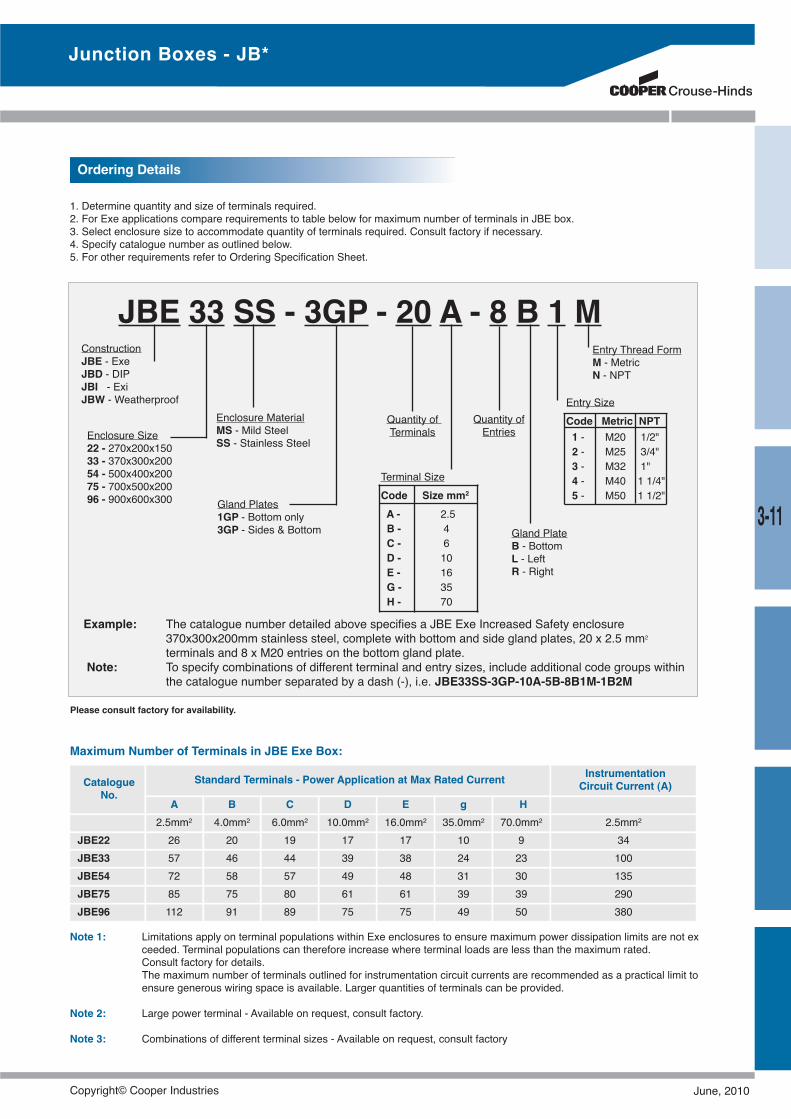
1. Determine quantity and size of terminals required.2. For Exe applications compare requirements to table below for maximum number of terminals in JBE box.3. Select enclosure size to accommodate quantity of terminals required. Consult factory if necessary.4. Specify catalogue number as outlined below.5. For other requirements refer to Ordering Specification Sheet.
Maximum Number of Terminals in JBE Exe Box:
Note 1: Limitations apply on terminal populations within Exe enclosures to ensure maximum power dissipation limits are not exceeded. Terminal populations can therefore increase where terminal loads are less than the maximum rated.Consult factory for details.The maximum number of terminals outlined for instrumentation circuit currents are recommended as a practical limit toensure generous wiring space is available. Larger quantities of terminals can be provided.
Note 2: Large power terminal - Available on request, consult factory.
Note 3: Combinations of different terminal sizes - Available on request, consult factory
JBE 33 SS - 3GP - 20 A - 8 B 1 M
Example: The catalogue number detailed above specifies a JBE Exe Increased Safety enclosure370x300x200mm stainless steel, complete with bottom and side gland plates, 20 x 2.5 mm2
terminals and 8 x M20 entries on the bottom gland plate.Note: To specify combinations of different terminal and entry sizes, include additional code groups within
the catalogue number separated by a dash (-), i.e. JBE33SS-3GP-10A-5B-8B1M-1B2M
ConstructionJBE - ExeJBD - DIPJBI - ExiJBW - Weatherproof
Enclosure Size22 - 270x200x15033 - 370x300x20054 - 500x400x20075 - 700x500x20096 - 900x600x300
Quantity ofTerminals
Terminal SizeCode Size mm2
A - 2.5B - 4C - 6D - 10E - 16G - 35H - 70
Quantity ofEntries
Entry SizeCode Metric NPT1 - M20 1/2"2 - M25 3/4"3 - M32 1"4 - M40 1 1/4"5 - M50 1 1/2"
Gland PlateB - BottomL - LeftR - Right
Entry Thread FormM - MetricN - NPT
Enclosure MaterialMS - Mild SteelSS - Stainless Steel
Gland Plates1GP - Bottom only3GP - Sides & Bottom
Ordering Details
CatalogueNo.
Standard Terminals - Power Application at Max Rated Current InstrumentationCircuit Current (A)
A B C D E g H2.5mm2 4.0mm2 6.0mm2 10.0mm2 16.0mm2 35.0mm2 70.0mm2 2.5mm2
JBE22 26 20 19 17 17 10 9 34JBE33 57 46 44 39 38 24 23 100JBE54 72 58 57 49 48 31 30 135JBE75 85 75 80 61 61 39 39 290JBE96 112 91 89 75 75 49 50 380
Junction Boxes - JB*
Please consult factory for availability.
3-11
Copyright© Cooper Industries June, 2010
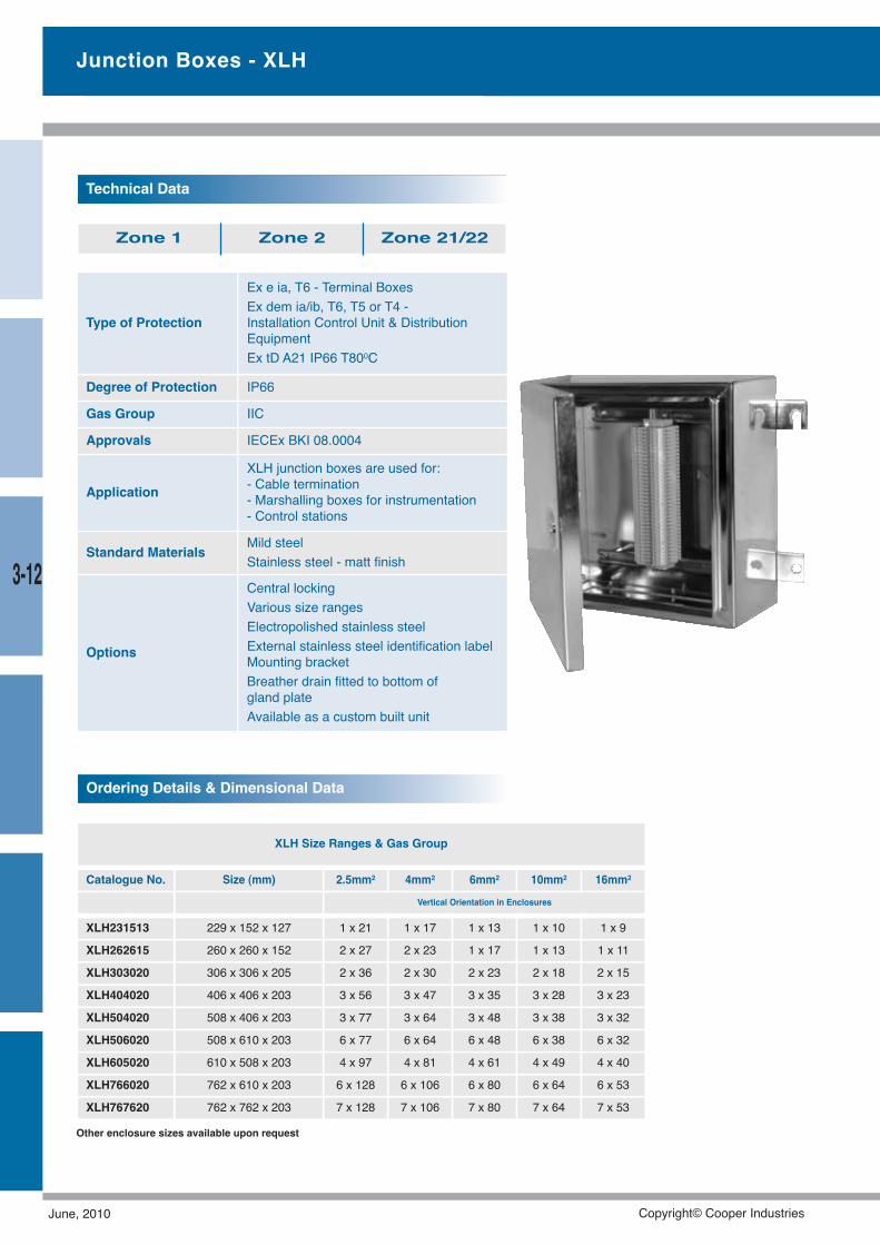
Junction Boxes - XLH
Type of Protection
Ex e ia, T6 - Terminal BoxesEx dem ia/ib, T6, T5 or T4 -Installation Control Unit & DistributionEquipmentEx tD A21 IP66 T800C
Degree of Protection IP66
Gas Group IIC
Approvals IECEx BKI 08.0004
ApplicationXLH junction boxes are used for:- Cable termination- Marshalling boxes for instrumentation- Control stations
Standard Materials Mild steelStainless steel - matt finish
Options
Central lockingVarious size rangesElectropolished stainless steelExternal stainless steel identification labelMounting bracketBreather drain fitted to bottom ofgland plateAvailable as a custom built unit
Technical Data
Zone 1 Zone 2 Zone 21/22
Ordering Details & Dimensional Data
XLH Size Ranges & Gas Group
Catalogue No. Size (mm) 2.5mm2 4mm2 6mm2 10mm2 16mm2
Vertical Orientation in Enclosures
XLH231513 229 x 152 x 127 1 x 21 1 x 17 1 x 13 1 x 10 1 x 9
XLH262615 260 x 260 x 152 2 x 27 2 x 23 1 x 17 1 x 13 1 x 11
XLH303020 306 x 306 x 205 2 x 36 2 x 30 2 x 23 2 x 18 2 x 15
XLH404020 406 x 406 x 203 3 x 56 3 x 47 3 x 35 3 x 28 3 x 23
XLH504020 508 x 406 x 203 3 x 77 3 x 64 3 x 48 3 x 38 3 x 32
XLH506020 508 x 610 x 203 6 x 77 6 x 64 6 x 48 6 x 38 6 x 32
XLH605020 610 x 508 x 203 4 x 97 4 x 81 4 x 61 4 x 49 4 x 40
XLH766020 762 x 610 x 203 6 x 128 6 x 10⁶ 6 x 80 6 x 64 6 x 53
XLH767620 762 x 762 x 203 7 x 128 7 x 10⁶ 7 x 80 7 x 64 7 x 53
Other enclosure sizes available upon request
3-12
June, 2010 Copyright© Cooper Industries
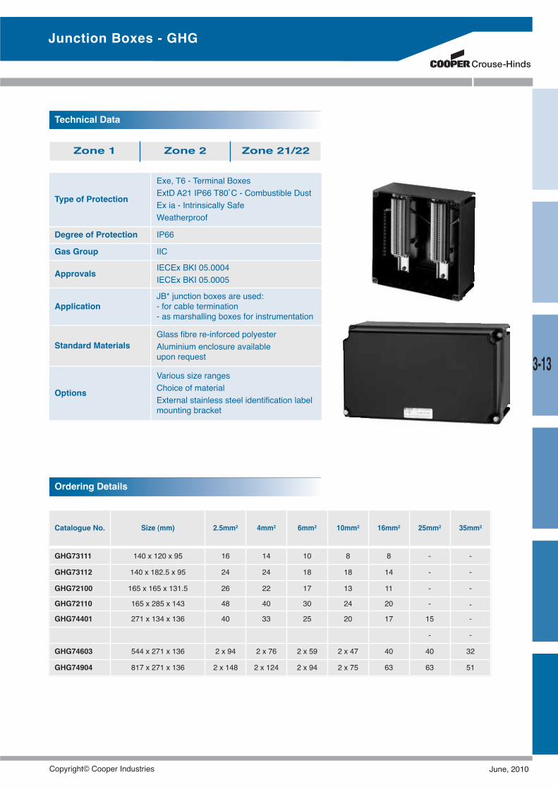
Type of Protection
Exe, T6 - Terminal BoxesExtD A21 IP66 T80˚C - Combustible DustEx ia - Intrinsically SafeWeatherproof
Degree of Protection IP66
Gas Group IIC
Approvals IECEx BKI 05.0004IECEx BKI 05.0005
ApplicationJB* junction boxes are used:- for cable termination- as marshalling boxes for instrumentation
Standard MaterialsGlass fibre re-inforced polyesterAluminium enclosure availableupon request
Options
Various size rangesChoice of materialExternal stainless steel identification labelmounting bracket
Technical Data
Zone 1 Zone 2 Zone 21/22
Junction Boxes - GHG
Ordering Details
Catalogue No. Size (mm) 2.5mm2 4mm2 6mm2 10mm2 16mm2 25mm2 35mm2
GHG73111 140 x 120 x 95 16 14 10 8 8 - -
GHG73112 140 x 182.5 x 95 24 24 18 18 14 - -
GHG72100 165 x 165 x 131.5 26 22 17 13 11 - -
GHG72110 165 x 285 x 143 48 40 30 24 20 - -
GHG74401 271 x 134 x 136 40 33 25 20 17 15 -
- -
GHG74603 544 x 271 x 136 2 x 94 2 x 76 2 x 59 2 x 47 40 40 32
GHG74904 817 x 271 x 136 2 x 148 2 x 124 2 x 94 2 x 75 63 63 51
3-13
Copyright© Cooper Industries June, 2010
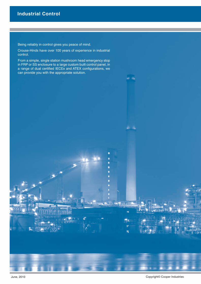
Industrial Control
Being reliably in control gives you peace of mind.Crouse-Hinds have over 100 years of experience in industrialcontrol.From a simple, single station mushroom head emergency stopin FRP or SS enclosure to a large custom built control panel, ina range of dual certified IECEx and ATEX configurations, wecan provide you with the appropriate solution.
June, 2010 Copyright© Cooper Industries
4-1
Industrial Control
Industrial ControlDSA - Exd START/STOP & Control Switches ................4-2GHG44 - Exe d, ExtD Control Panel ..............................4-5EMD - Exd ib Earth Monitoring Device............................4-7GHG273 - Exe d, ExtD Lighting Swich............................4-8GHG29 - Exde Remote Control Unit ..............................4-9ESA - Exd Isolator ........................................................4-10GHG26 - Exe d, Ex tD Isolator ......................................4-12EMA - Exd DOL Starter ................................................4-13EPBA - Exd Panel Board ..............................................4-14
Copyright© Cooper Industries June, 2010
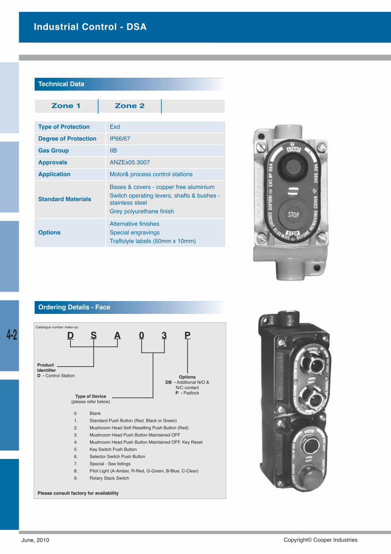
4-2
Type of Protection Exd
Degree of Protection IP66/67
Gas Group IIB
Approvals ANZEx05.3007
Application Motor& process control stations
Standard Materials
Bases & covers - copper free aluminiumSwitch operating levers, shafts & bushes -stainless steelGrey polyurethane finish
OptionsAlternative finishesSpecial engravingsTraffolyte labels (50mm x 10mm)
Technical Data
Zone 1 Zone 2
Catalogue number make-up:
D S A 0 3
ProductIdentifierD - Control Station
P
Type of Device(please refer below)
OptionsDB - Additional N/O &
N/C contactP - Padlock
Ordering Details - Face
0 Blank1. Standard Push Button (Red, Black or Green)2. Mushroom Head Self-Resetting Push Button (Red)3. Mushroom Head Push Button Maintained OFF4. Mushroom Head Push Button Maintained OFF, Key Reset5. Key Switch Push Button6. Selector Switch Push Button7. Special - See listings8. Pilot Light (A-Amber, R-Red, G-Green, B-Blue, C-Clear)9. Rotary Stack Switch
Industrial Control - DSA
Please consult factory for availability
June, 2010 Copyright© Cooper Industries

4-3
Industrial Control - DSA
Push Button Ordering Details
Catalogue No. Description
DSA01 Standard push button
DSA02 Mushroom head push button, spring returnDSA03
DSA03P
Mushroom head push button, latchingMushroom head push button, latching & padlockable
DSA04 Mushroom head push button, latching & key re-set
DSA05 Key switch push button
DSA08 Indicating light (add G, R, A, B, C for colours)
DSA11 1 x start push button & 1 x stop push button
DSA12 1 x start push button & 1 x mushroom head stop spring return
DSA13 1 x start push button & 1 x mushroom head stop latching
DSA13P 1 x start push button & 1 x mushroom head stop latching & padlockable
DSA14 1 x start push button & 1 x mushroom head stop key re-setDSA15 1 x start push button & 1 x key switch push buttonDSA18 1 x start push button & 1 x indicating light (add G, R, A, B, C for colours)
DSA88 2 x indicating lights (add G, R, A, B, C for colours)
Switch Ordering Details
Catalogue No. Description
DSA9-A178 10A, OFF - RUN - START, spring return from START - RUN
DSA9-A201 20A, 2 pole, 2 positions ON - OFF
DSA9-A202 20A, 3 pole, 2 positions ON - OFF
DSA9-A203 20A, 4 pole, 2 positions ON - OFF
DSA9-A212 20A, 3 pole, 3 positions change-over with centre OFF
DSA9-A215 20A, 2 pole, 3 positions change over with centre OFF
DSA9-A221 20A, 2 pole, 2 positions change over
DSA9-A222 20A, 4 pole, 2 positions change over* Switch base DSAB ordered separately, see next page.
Copyright© Cooper Industries June, 2010
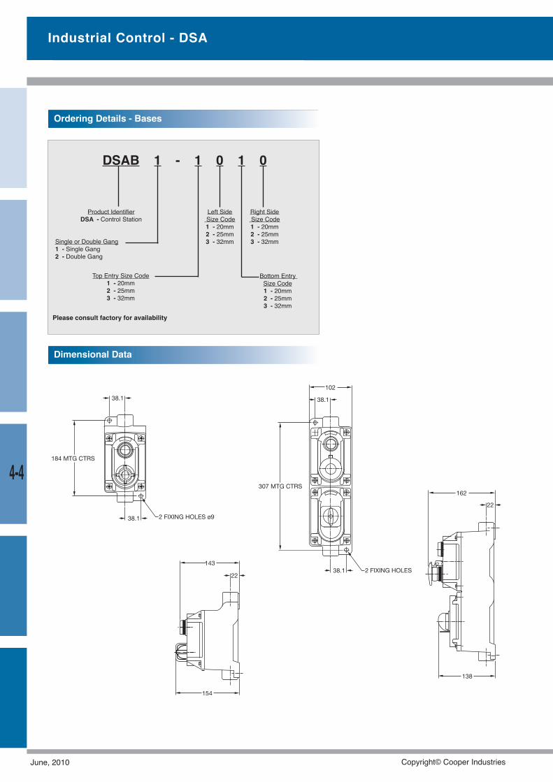
Industrial Control - DSA
Ordering Details - Bases
DSAB 1 - 1 0 1 0
Product IdentifierDSA - Control Station
Single or Double Gang1 - Single Gang2 - Double Gang
Top Entry Size Code1 - 20mm2 - 25mm3 - 32mm
Left SideSize Code1 - 20mm2 - 25mm3 - 32mm
Bottom EntrySize Code1 - 20mm2 - 25mm3 - 32mm
Right SideSize Code1 - 20mm2 - 25mm3 - 32mm
Dimensional Data
Please consult factory for availability
4-4
June, 2010 Copyright© Cooper Industries
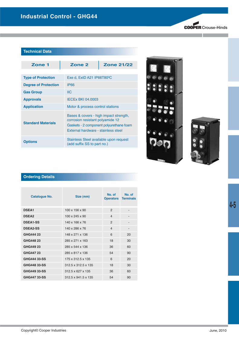
Industrial Control - GHG44
Type of Protection Exe d, ExtD A21 IP66T800C
Degree of Protection IP66
Gas Group IIC
Approvals IECEx BKI 04.0003
Application Motor & process control stations
Standard Materials
Bases & covers - high impact strength,corrosion resistant polyamide 12Gaskets - 2 component polyurethane foamExternal hardware - stainless steel
Options Stainless Steel available upon request(add suffix SS to part no.)
Technical Data
Zone 1 Zone 2 Zone 21/22
Ordering Details
Catalogue No. Size (mm) No. ofOperators
No. ofTerminals
DSEA1 100 x 156 x 90 2 -
DSEA2 100 x 245 x 90 4 -
DSEA1-SS 140 x 166 x 76 2 -
DSEA2-SS 140 x 286 x 76 4 -
GHG444 23 148 x 271 x 136 6 20
GHG448 23 285 x 271 x 163 18 30
GHG449 23 285 x 544 x 136 36 60
GHG447 23 285 x 817 x 136 54 90
GHG444 33-SS 175 x 312.5 x 135 6 20
GHG448 33-SS 312.5 x 312.5 x 135 18 30
GHG449 33-SS 312.5 x 627 x 135 36 60
GHG447 33-SS 312.5 x 941.5 x 135 54 90
4-5
Copyright© Cooper Industries June, 2010
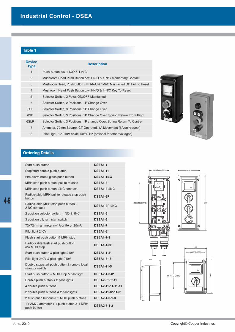
Ordering Details
DeviceType Description
1 Push Button c/w 1-N/O & 1-N/C
2 Mushroom Head Push Button c/w 1-N/O & 1-N/C Momentary Contact
3 Mushroom Head, Push Button c/w 1-N/O & 1-N/C Maintained Off, Pull To Reset
4 Mushroom Head Push Button c/w 1-N/O & 1-N/C Key To Reset
5 Selector Switch, 2 Poles ON/OFF Maintained
6 Selector Switch, 2 Positions, 1P Change Over
6SL Selector Switch, 3 Positions, 1P Change Over
6SR Selector Switch, 3 Positions, 1P Change Over, Spring Return From Right
6SLR Selector Switch, 3 Positions, 1P change Over, Spring Return To Centre
7 Ammeter, 72mm Square, CT Operated, 1A Movement (5A on request)
8 Pilot Light, 12-240V ac/dc, 50/60 Hz (optional for other voltages)
Table 1
Industrial Control - DSEA
Start push button DSEA1-1
Stop/start double push button DSEA1-11
Fire alarm break glass push button DSEA1-1BG
MRH stop push button, pull to release DSEA1-3
MRH stop push button, 2NC contacts DSEA1-3-2NCPadlockable MRH pull to release stop pushbutton DSEA1-3P
Padlockable MRH stop push button -2 NC contacts DSEA1-3P-2NC
2 position selector switch, 1 NO & 1NC DSEA1-5
3 position off, run, start switch DSEA1-6
72x72mm ammeter n=1A or 5A or 20mA DSEA1-7
Pilot light 240V DSEA1-8*
Flush start push button & MRH stop DSEA1-1-3Padlockable flush start push buttonc/w MRH stop DSEA1-1-3P
Start push button & pilot light 240V DSEA1-1-8*
Pilot light 240V & pilot light 240V DSEA1-8*-8*Double stop/start push button & remote localselector switch DSEA1-11-5
Start push button + MRH stop & pilot light DSEA2-1-3-8*
Double push button + 2 pilot lights DSEA2-8*-8*-11
4 double push buttons DSEA2-11-11-11-11
2 double push buttons & 2 pilot lights DSEA2-11-8*-11-8*
2 flush push buttons & 2 MRH push buttons DSEA2-1-3-1-31 x AM72 ammeter + 1 push button & 1 MRHpush button DSEA2-7-1-3
4-6 188 MTG CTRS
98 MTG CTRS
88 MTG CTRS
88 MTG CTRS
100
100
160
250
90
June, 2010 Copyright© Cooper Industries
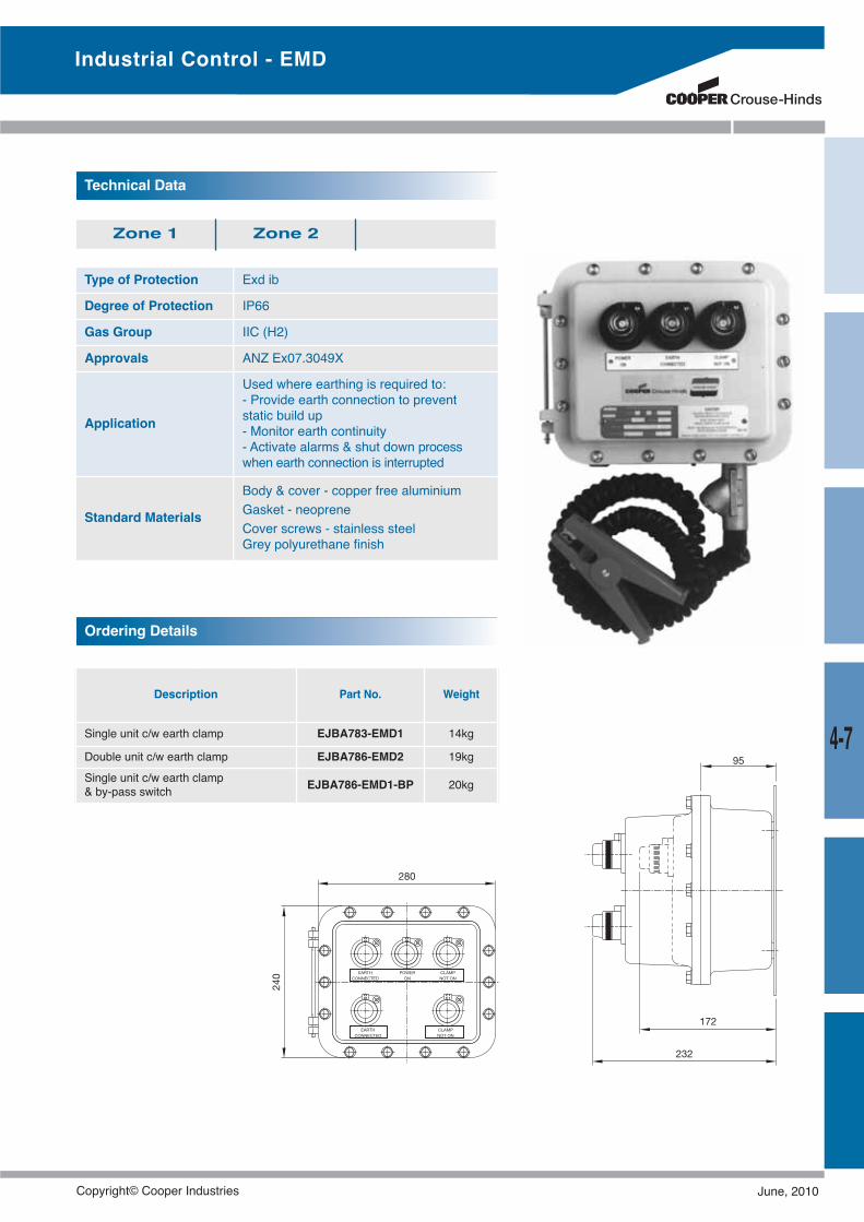
Type of Protection Exd ib
Degree of Protection IP66
Gas Group IIC (H2)
Approvals ANZ Ex07.3049X
Application
Used where earthing is required to:- Provide earth connection to preventstatic build up- Monitor earth continuity- Activate alarms & shut down processwhen earth connection is interrupted
Standard Materials
Body & cover - copper free aluminiumGasket - neopreneCover screws - stainless steelGrey polyurethane finish
Technical Data
Zone 1 Zone 2
Description Part No. Weight
Single unit c/w earth clamp EJBA783-EMD1 14kg
Double unit c/w earth clamp EJBA786-EMD2 19kgSingle unit c/w earth clamp& by-pass switch EJBA786-EMD1-BP 20kg
Ordering Details
Industrial Control - EMD
4-7
Copyright© Cooper Industries June, 2010
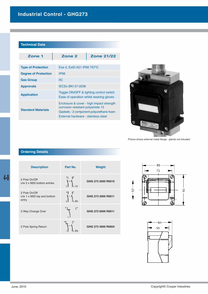
Description Part No. Weight
2 Pole On/Offc/w 2 x M20 bottom entries GHG 273 2000 R0010
2 Pole On/Offc/w 1 x M20 top and bottomentry
GHG 273 2000 R0011
2 Way Change Over GHG 273 6000 R0011
2 Pole Spring Return GHG 273 4000 R0004
Industrial Control - GHG273
Type of Protection Exe d, ExtD A21 IP66 T670C
Degree of Protection IP66
Gas Group IIC
Approvals IECEx BKI 07.0036
Application Toggle ON/OFF & lighting control switchEase of operation whilst wearing gloves
Standard Materials
Enclosure & cover - high impact strengthcorrosion resistant polyamide 12Gaskets - 2 component polyurethane foamExternal hardware - stainless steel
Technical Data
Zone 1 Zone 2 Zone 21/22
Ordering Details
Picture shows external metal flange - glands not inlcuded
4-8
June, 2010 Copyright© Cooper Industries
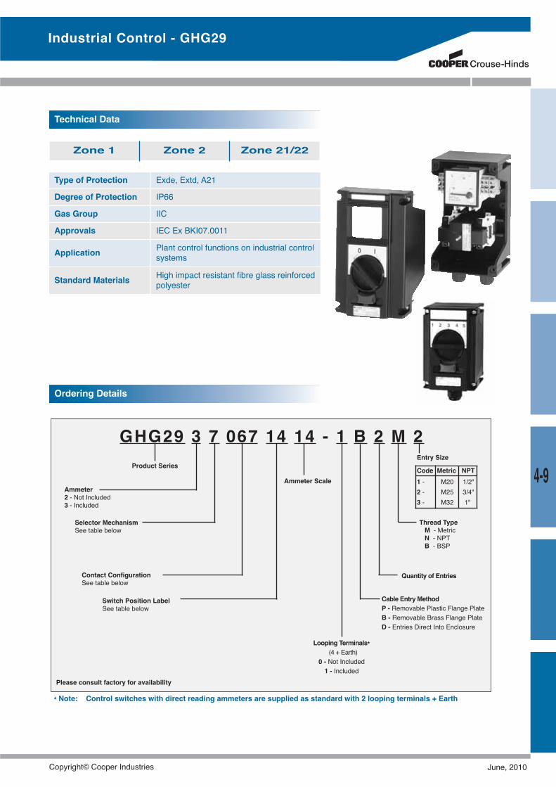
Type of Protection Exde, Extd, A21
Degree of Protection IP66
Gas Group IIC
Approvals IEC Ex BKI07.0011
Application Plant control functions on industrial controlsystems
Standard Materials High impact resistant fibre glass reinforcedpolyester
Technical Data
Zone 1 Zone 2 Zone 21/22
GHG29 3 7 067 14 14 - 1 B 2 M 2Product Series
Ammeter2 - Not Included3 - Included
Selector MechanismSee table below
Contact ConfigurationSee table below
Switch Position LabelSee table below
Ammeter Scale
Looping Terminals*(4 + Earth)
0 - Not Included1 - Included
Quantity of Entries
Thread TypeM - MetricN - NPTB - BSP
Entry Size
Code Metric NPT1 - M20 1/2"2 - M25 3/4"3 - M32 1"
* Note: Control switches with direct reading ammeters are supplied as standard with 2 looping terminals + Earth
Cable Entry MethodP - Removable Plastic Flange PlateB - Removable Brass Flange PlateD - Entries Direct Into Enclosure
Ordering Details
Please consult factory for availability
Industrial Control - GHG29
4-9
Copyright© Cooper Industries June, 2010
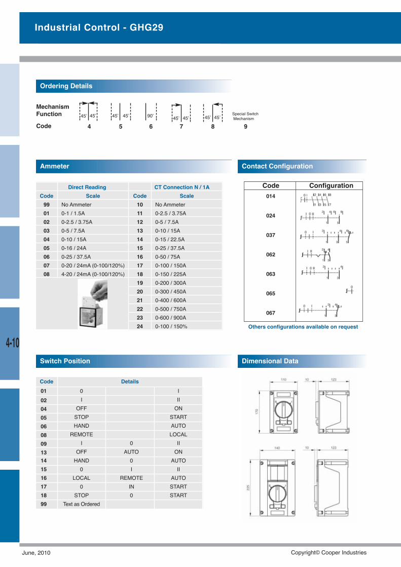
4-10
Code Configuration
Industrial Control - GHG29
450 450 450 450 900
450 450 450 450
014
024
037
062
063
065
067
4 5 6 7 8 9
Special SwitchMechanism
MechanismFunction
Code
Others configurations available on request
Ordering Details
Ammeter
Direct Reading CT Connection N / 1ACode Scale Code Scale99 No Ammeter 10 No Ammeter01 0-1 / 1.5A 11 0-2.5 / 3.75A02 0-2.5 / 3.75A 12 0-5 / 7.5A03 0-5 / 7.5A 13 0-10 / 15A04 0-10 / 15A 14 0-15 / 22.5A05 0-16 / 24A 15 0-25 / 37.5A06 0-25 / 37.5A 16 0-50 / 75A07 0-20 / 24mA (0-100/120%) 17 0-100 / 150A08 4-20 / 24mA (0-100/120%) 18 0-150 / 225A
19 0-200 / 300A20 0-300 / 450A21 0-400 / 600A22 0-500 / 750A23 0-600 / 900A24 0-100 / 150%
Switch Position
Contact Configuration
Dimensional Data
Code Details01 0 I02 I II04 OFF ON05 STOP START06 HAND AUTO08 REMOTE LOCAL09 I 0 II13 OFF AUTO ON14 HAND 0 AUTO15 0 I II16 LOCAL REMOTE AUTO17 0 IN START18 STOP 0 START99 Text as Ordered
June, 2010 Copyright© Cooper Industries
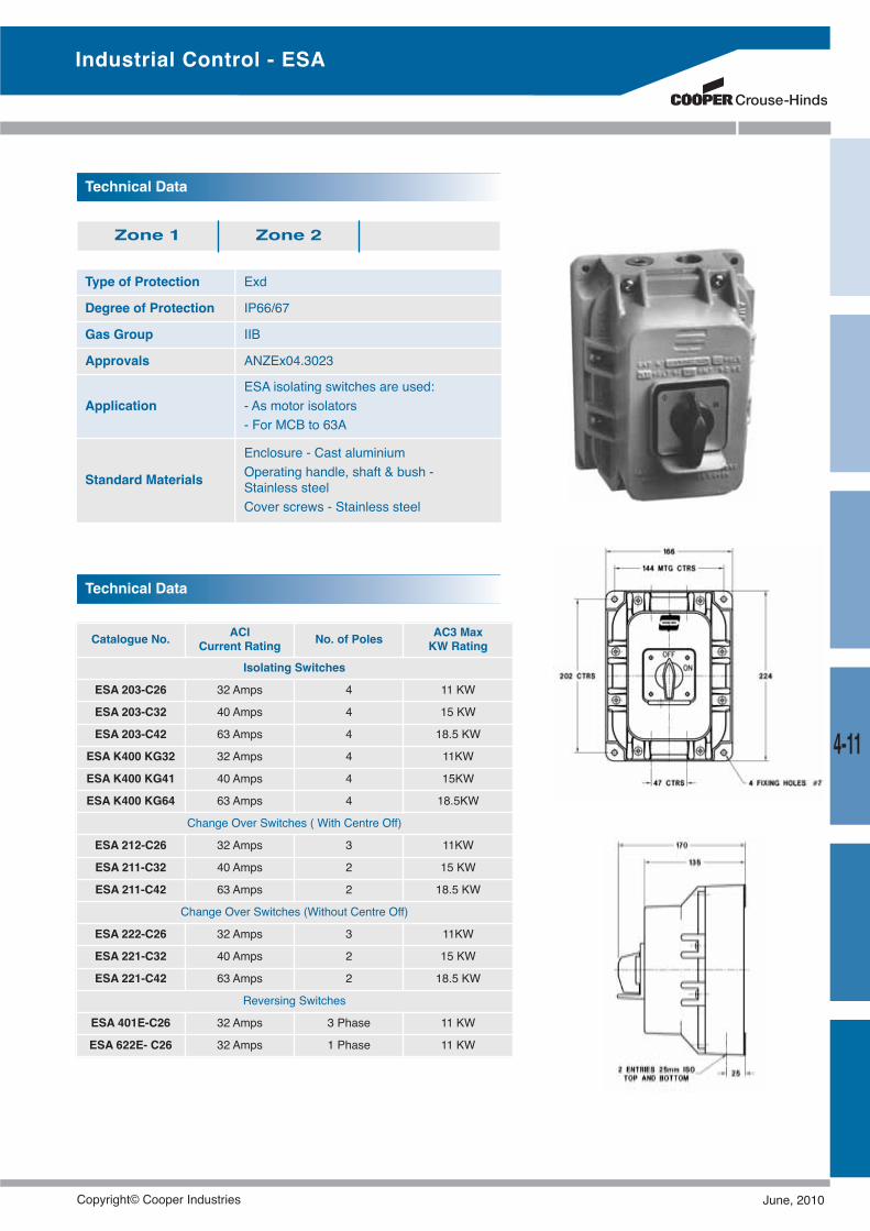
4-11
Industrial Control - ESA
Type of Protection Exd
Degree of Protection IP66/67
Gas Group IIB
Approvals ANZEx04.3023
ApplicationESA isolating switches are used:- As motor isolators- For MCB to 63A
Standard Materials
Enclosure - Cast aluminiumOperating handle, shaft & bush -Stainless steelCover screws - Stainless steel
Technical Data
Zone 1 Zone 2
Catalogue No. ACICurrent Rating No. of Poles AC3 Max
KW RatingIsolating Switches
ESA 203-C26 32 Amps 4 11 KW
ESA 203-C32 40 Amps 4 15 KW
ESA 203-C42 63 Amps 4 18.5 KW
ESA K400 KG32 32 Amps 4 11KW
ESA K400 KG41 40 Amps 4 15KW
ESA K400 KG64 63 Amps 4 18.5KW
Change Over Switches ( With Centre Off)
ESA 212-C26 32 Amps 3 11KW
ESA 211-C32 40 Amps 2 15 KW
ESA 211-C42 63 Amps 2 18.5 KW
Change Over Switches (Without Centre Off)
ESA 222-C26 32 Amps 3 11KW
ESA 221-C32 40 Amps 2 15 KW
ESA 221-C42 63 Amps 2 18.5 KW
Reversing Switches
ESA 401E-C26 32 Amps 3 Phase 11 KW
ESA 622E- C26 32 Amps 1 Phase 11 KW
Technical Data
Copyright© Cooper Industries June, 2010
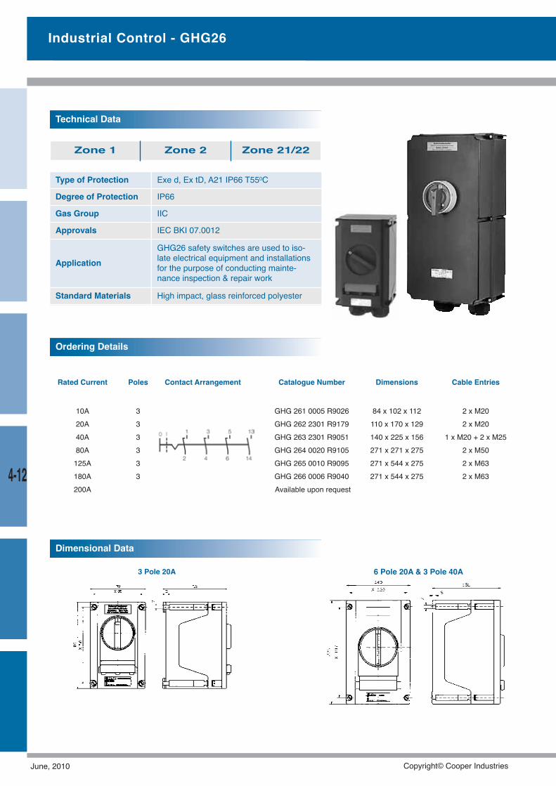
Rated Current Poles Contact Arrangement Catalogue Number Dimensions Cable Entries
10A 3 GHG 261 0005 R9026 84 x 102 x 112 2 x M2020A 3 GHG 262 2301 R9179 110 x 170 x 129 2 x M2040A 3 GHG 263 2301 R9051 140 x 225 x 156 1 x M20 + 2 x M2580A 3 GHG 264 0020 R9105 271 x 271 x 275 2 x M50125A 3 GHG 265 0010 R9095 271 x 544 x 275 2 x M63180A 3 GHG 266 0006 R9040 271 x 544 x 275 2 x M63200A Available upon request
3 Pole 20A 6 Pole 20A & 3 Pole 40A
Type of Protection Exe d, Ex tD, A21 IP66 T550C
Degree of Protection IP66
Gas Group IIC
Approvals IEC BKI 07.0012
ApplicationGHG26 safety switches are used to iso-late electrical equipment and installationsfor the purpose of conducting mainte-nance inspection & repair work
Standard Materials High impact, glass reinforced polyester
Technical Data
Zone 1 Zone 2 Zone 21/22
Ordering Details
Dimensional Data
Industrial Control - GHG26
4-12
June, 2010 Copyright© Cooper Industries
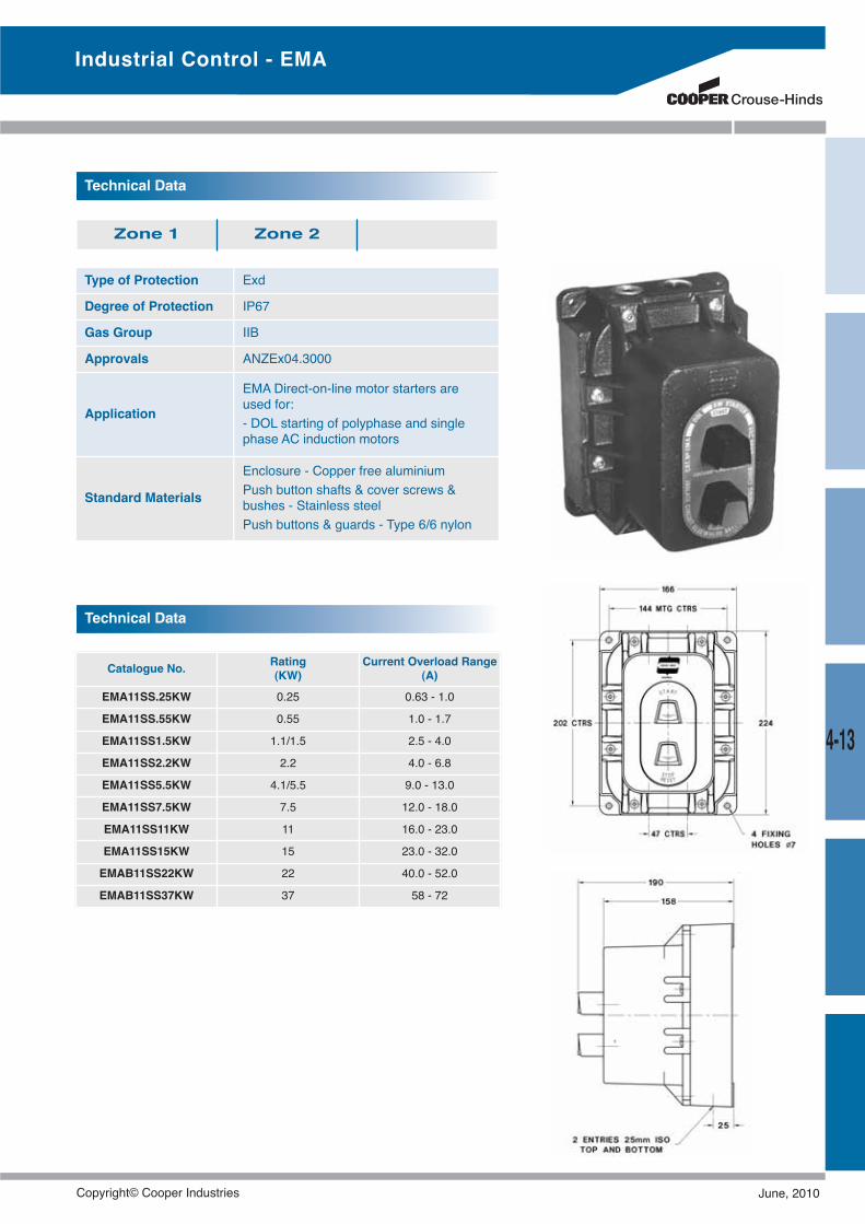
Type of Protection Exd
Degree of Protection IP67
Gas Group IIB
Approvals ANZEx04.3000
Application
EMA Direct-on-line motor starters areused for:- DOL starting of polyphase and singlephase AC induction motors
Standard Materials
Enclosure - Copper free aluminiumPush button shafts & cover screws &bushes - Stainless steelPush buttons & guards - Type 6/6 nylon
Technical Data
Zone 1 Zone 2
Technical Data
Catalogue No. Rating(KW)
Current Overload Range(A)
EMA11SS.25KW 0.25 0.63 - 1.0
EMA11SS.55KW 0.55 1.0 - 1.7
EMA11SS1.5KW 1.1/1.5 2.5 - 4.0
EMA11SS2.2KW 2.2 4.0 - 6.8
EMA11SS5.5KW 4.1/5.5 9.0 - 13.0
EMA11SS7.5KW 7.5 12.0 - 18.0
EMA11SS11KW 11 16.0 - 23.0
EMA11SS15KW 15 23.0 - 32.0
EMAB11SS22KW 22 40.0 - 52.0
EMAB11SS37KW 37 58 - 72
Industrial Control - EMA
4-13
Copyright© Cooper Industries June, 2010
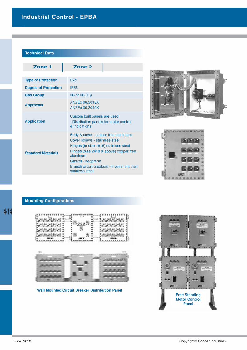
Industrial Control - EPBA
Type of Protection Exd
Degree of Protection IP66
Gas Group IIB or IIB (H2)
Approvals ANZEx 06.3018XANZEx 06.3049X
ApplicationCustom built panels are used:- Distribution panels for motor control& indications
Standard Materials
Body & cover - copper free aluminumCover screws - stainless steelHinges (to size 1616) stainless steelHinges (size 2418 & above) copper freealuminumGasket - neopreneBranch circuit breakers - investment caststainless steel
Technical Data
Zone 1 Zone 2
Wall Mounted Circuit Breaker Distribution PanelFree StandingMotor Control
Panel
Mounting Configurations
4-14
June, 2010 Copyright© Cooper Industries
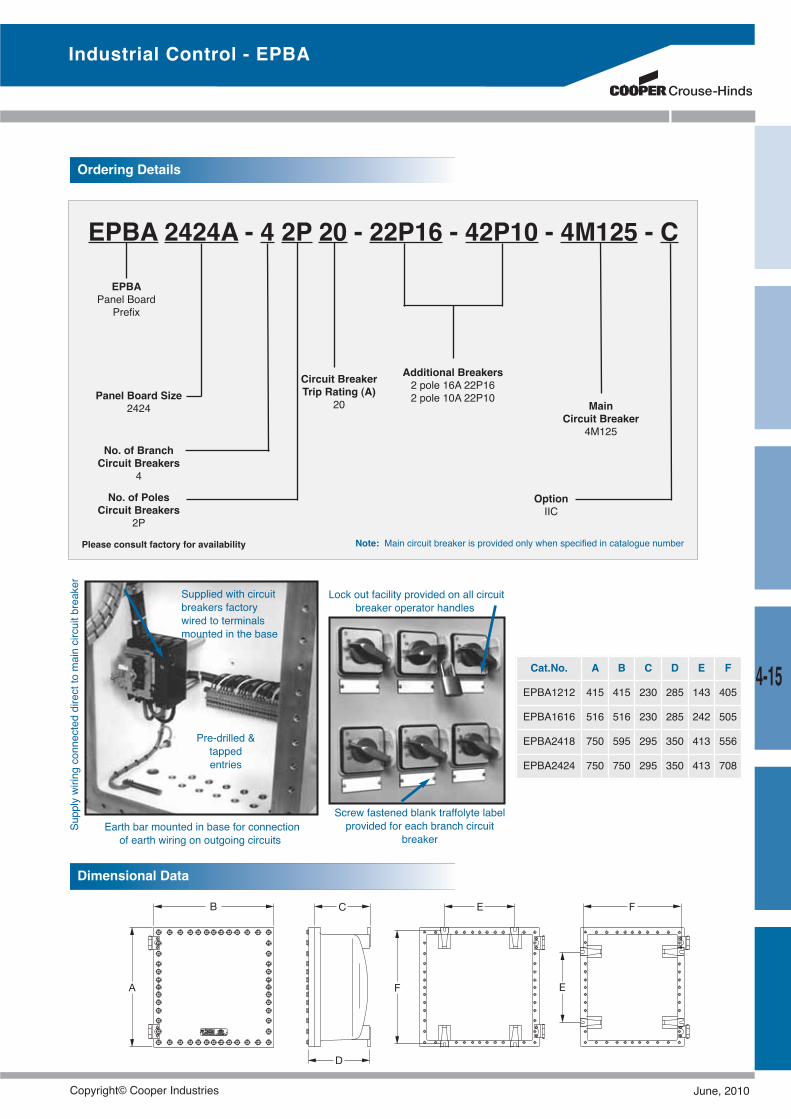
Screw fastened blank traffolyte labelprovided for each branch circuit
breaker
Pre-drilled &tappedentries
Earth bar mounted in base for connectionof earth wiring on outgoing circuits
Lock out facility provided on all circuitbreaker operator handles
Supplied with circuitbreakers factorywired to terminalsmounted in the base
Supplywiringconnecteddirecttomaincircuitbreaker
EPBA 2424A - 4 2P 20 - 22P16 - 42P10 - 4M125 - C
EPBAPanel Board
Prefix
Panel Board Size2424
Ordering Details
No. of BranchCircuit Breakers
4
No. of PolesCircuit Breakers
2P
Circuit BreakerTrip Rating (A)
20
Additional Breakers2 pole 16A 22P162 pole 10A 22P10
MainCircuit Breaker
4M125
OptionIIC
Note: Main circuit breaker is provided only when specified in catalogue numberPlease consult factory for availability
Cat.No. A B C D E F
EPBA1212 415 415 230 285 143 405
EPBA1616 516 516 230 285 242 505
EPBA2418 750 595 295 350 413 556
EPBA2424 750 750 295 350 413 708
Dimensional Data
Industrial Control - EPBA
4-15
Copyright© Cooper Industries June, 2010
Hazardous Area Lighting
Crouse-Hinds and CEAG are leading the way in lighting uphazardous and ardous areas with many bright ideas.The popular & reliable HID Champs® have been a wellproven fixture in many industries for a number of years whilstthe technologically advanced, unique and robust eLLK stan-dard fluorescent fixtures provide total lighting solutions underany condition.
June, 2010 Copyright© Cooper Industries
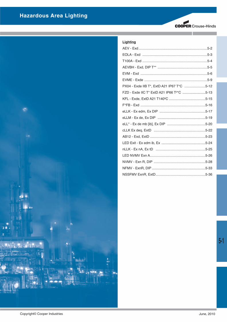
5-1
Hazardous Area Lighting
LightingAEV - Exd........................................................................5-2EOLA - Exd ....................................................................5-3T100A - Exd ....................................................................5-4AEVBH - Exd, DIP T** ....................................................5-5EVM - Exd ......................................................................5-6EVME - Exde ..................................................................5-9PX04 - Exde IIB T*, ExtD A21 IP67 T*C ......................5-12FZD - Exde IIC T* ExtD A21 IP66 T0*C ........................5-13KFL - Exde, ExtD A21 T1400C ......................................5-15F*FB - Exd ....................................................................5-16eLLK - Ex edm, Ex DIP ................................................5-17eLLM - Ex de, Ex DIP ..................................................5-19eLL* - Ex de mb [ib], Ex DIP ........................................5-20cLLK Ex deq, ExtD ......................................................5-22AB12 - Exd, ExtD ..........................................................5-23LED Exit - Ex edm ib, Ex ..............................................5-24nLLK - Ex nA, Ex tD ....................................................5-25LED NVMV Exn A..........................................................5-26NVMV - Exn R, DIP ......................................................5-28NFMV - ExnR, DIP ........................................................5-33NSSFMV ExnR, ExtD....................................................5-36
Copyright© Cooper Industries June, 2010
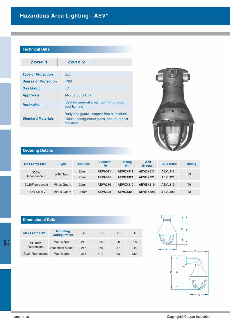
Type of Protection Exd
Degree of Protection IP66
Gas Group IIC
Approvals ANZEx 08.3007X
Application Ideal for general area, room or outdoorspot lighting
Standard MaterialsBody and guard - copper free aluminiumGlass - configurated glass, heat & impactresistant
Technical Data
Zone 1 Zone 2
Max Lamp Size Type Hub Size PendantMt
CeilingMt
WallBracket Bulk Head T Rating
300WIncandescent With Guard
20mm AEVA311 AEVCX311 AEVBX311 AEVJ311T3
25mm AEVA321 AEVCX321 AEVBX321 AEVJ321
Ordering Details
SL25Fluorescent Minus Guard 20mm AEVA310 AEVCX310 AEVBX310 AEVJ310 T6
160W SB MV Minus Guard 25mm AEVA320 AEVCX320 AEVBX320 AEVJ320 T3
Hazardous Area Lighting - AEV*
Max Lamp Size MountingConfiguration A B C D
Dimensional Data
SL 18WFluorescent
Wall Mount 216 390 368 318
Stanchion Mount 216 359 337 244
SL25 Fluorescent Wall Mount 216 441 413 333
5-2
June, 2010 Copyright© Cooper Industries
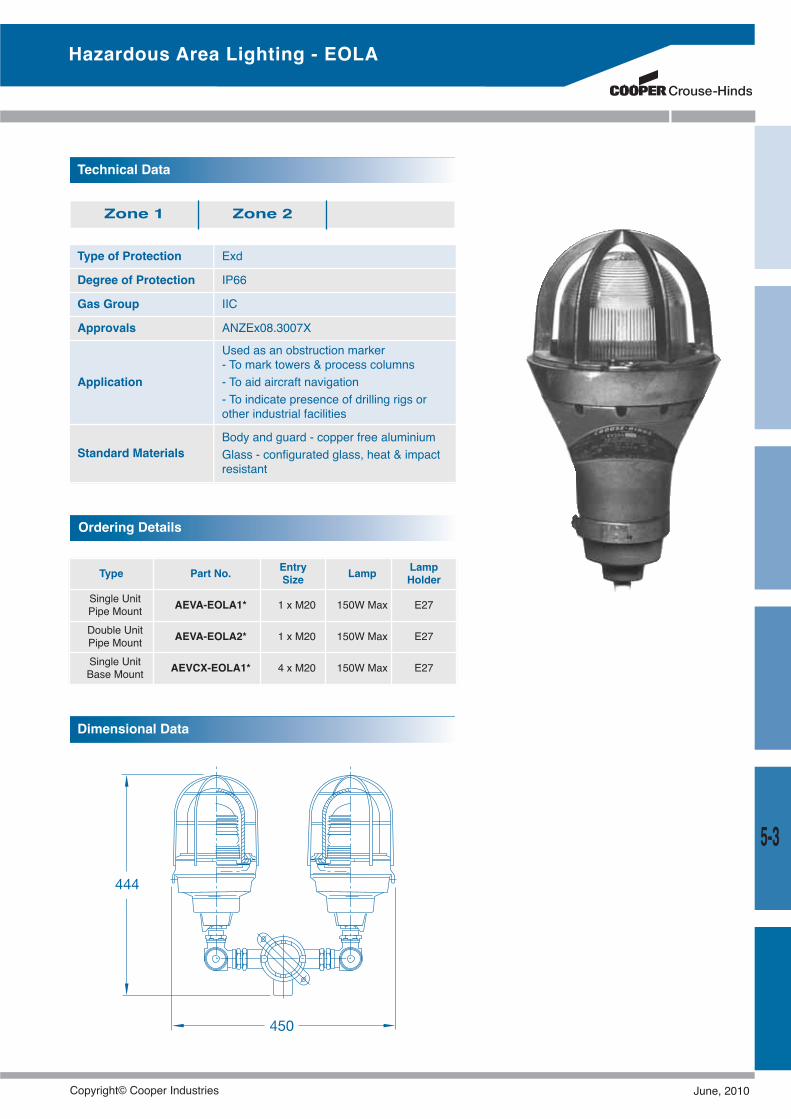
Hazardous Area Lighting - EOLA
Type of Protection Exd
Degree of Protection IP66
Gas Group IIC
Approvals ANZEx08.3007X
Application
Used as an obstruction marker- To mark towers & process columns- To aid aircraft navigation- To indicate presence of drilling rigs orother industrial facilities
Standard MaterialsBody and guard - copper free aluminiumGlass - configurated glass, heat & impactresistant
Technical Data
Zone 1 Zone 2
Type Part No. EntrySize Lamp Lamp
HolderSingle UnitPipe Mount AEVA-EOLA1* 1 x M20 150W Max E27
Double UnitPipe Mount AEVA-EOLA2* 1 x M20 150W Max E27
Single UnitBase Mount AEVCX-EOLA1* 4 x M20 150W Max E27
Ordering Details
5-3
Dimensional Data
Copyright© Cooper Industries June, 2010
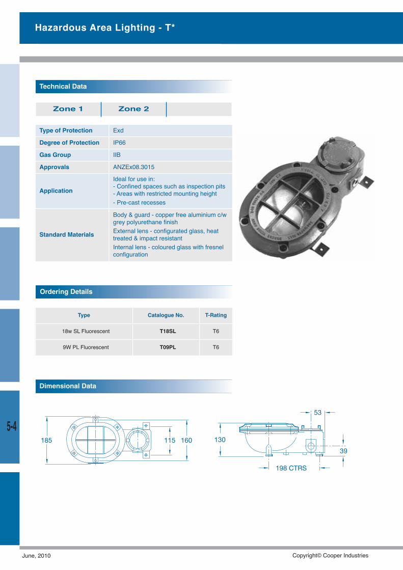
Type of Protection Exd
Degree of Protection IP66
Gas Group IIB
Approvals ANZEx08.3015
Application
Ideal for use in:- Confined spaces such as inspection pits- Areas with restricted mounting height- Pre-cast recesses
Standard Materials
Body & guard - copper free aluminium c/wgrey polyurethane finishExternal lens - configurated glass, heattreated & impact resistantInternal lens - coloured glass with fresnelconfiguration
Technical Data
Zone 1 Zone 2
Type Catalogue No. T-Rating
18w SL Fluorescent T18SL T6
9W PL Fluorescent T09PL T6
Ordering Details
Dimensional Data
Hazardous Area Lighting - T*
5-4
June, 2010 Copyright© Cooper Industries
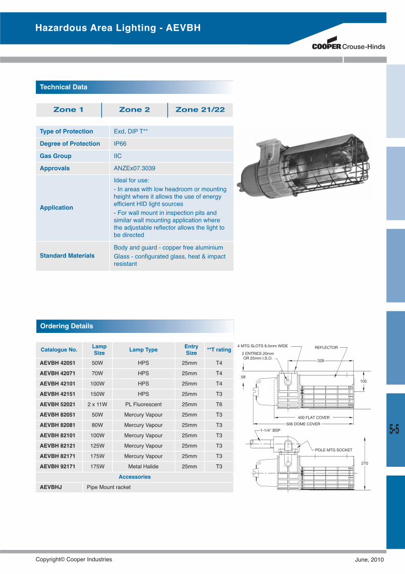
5-5
Hazardous Area Lighting - AEVBH
Type of Protection Exd, DIP T**
Degree of Protection IP66
Gas Group IIC
Approvals ANZEx07.3039
Application
Ideal for use:- In areas with low headroom or mountingheight where it allows the use of energyefficient HID light sources- For wall mount in inspection pits andsimilar wall mounting application wherethe adjustable reflector allows the light tobe directed
Standard MaterialsBody and guard - copper free aluminiumGlass - configurated glass, heat & impactresistant
Technical Data
Zone 1 Zone 2 Zone 21/22
Catalogue No. LampSize Lamp Type Entry
Size **T rating
AEVBH 42051 50W HPS 25mm T4
AEVBH 42071 70W HPS 25mm T4
AEVBH 42101 100W HPS 25mm T4
AEVBH 42151 150W HPS 25mm T3
AEVBH 52021 2 x 11W PL Fluorescent 25mm T6
AEVBH 82051 50W Mercury Vapour 25mm T3
AEVBH 82081 80W Mercury Vapour 25mm T3
AEVBH 82101 100W Mercury Vapour 25mm T3
AEVBH 82121 125W Mercury Vapour 25mm T3
AEVBH 82171 175W Mercury Vapour 25mm T3
AEVBH 92171 175W Metal Halide 25mm T3
Accessories
AEVBHJ Pipe Mount racket
Ordering Details
Copyright© Cooper Industries June, 2010
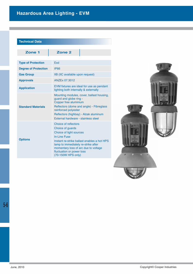
5-6
Type of Protection Exd
Degree of Protection IP66
Gas Group IIB (IIC available upon request)
Approvals ANZEx 07.3012
Application EVM fixtures are ideal for use as pendantlighting both internally & externally
Standard Materials
Mounting modules, cover, ballast housing,guard and globe ring -Copper free aluminiumReflectors (dome and angle) - Fibreglassreinforced polyesterReflectors (highbay) - Alzak aluminumExternal hardware - stainless steel
Options
Choice of reflectorsChoice of guardsChoice of light sourcesIn-Line FuseInstant re-strike ballast enables a hot HPSlamp to immediately re-strike aftermomentary loss of arc due to voltagefluctuation or power loss(70-150W HPS only)
Technical Data
Zone 1 Zone 2
Hazardous Area Lighting - EVM
June, 2010 Copyright© Cooper Industries
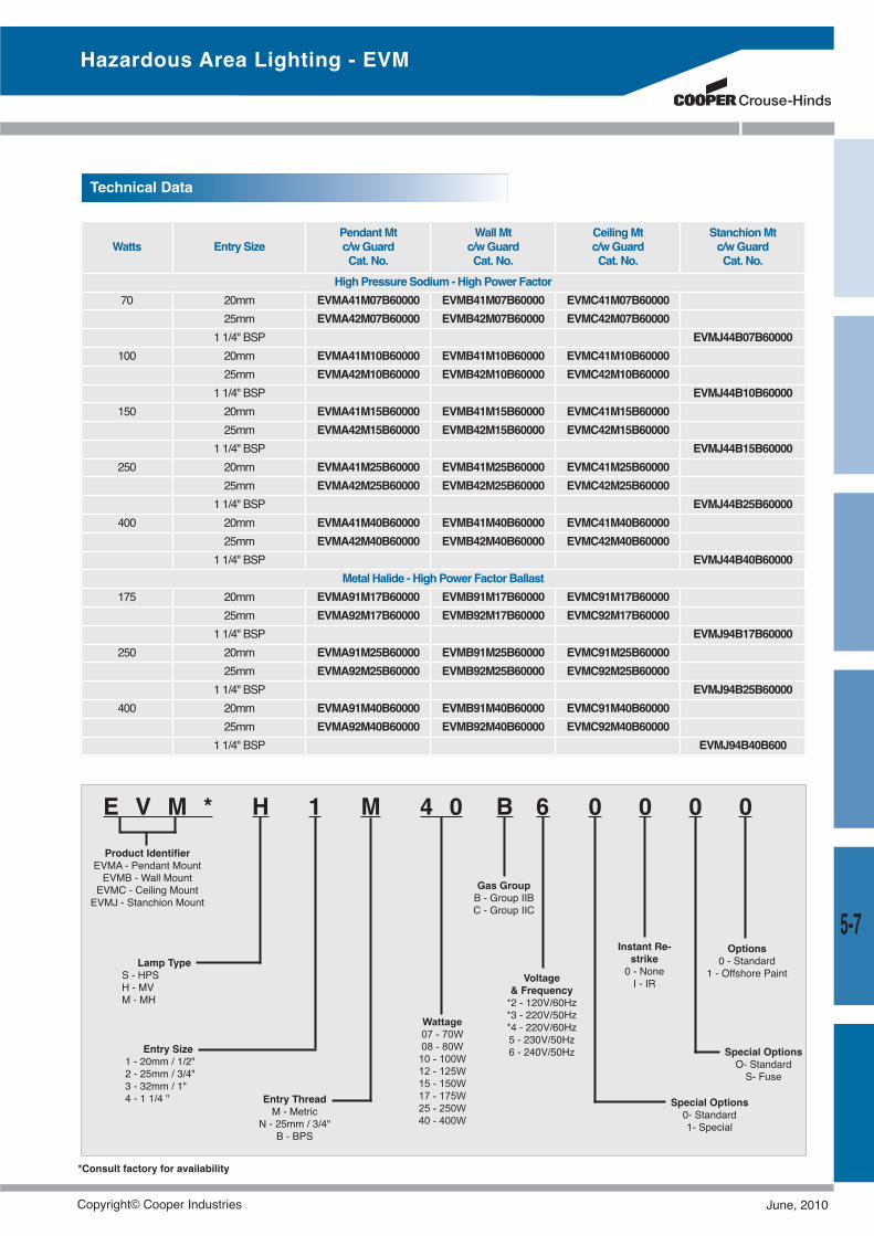
5-7
E V M * H 1 M 4 0 B 6 0 0 0 0
Hazardous Area Lighting - EVM
Watts Entry SizePendantMtc/wGuardCat. No.
WallMtc/wGuardCat. No.
CeilingMtc/wGuardCat. No.
StanchionMtc/wGuardCat. No.
HighPressure Sodium -HighPower Factor70 20mm EVMA41M07B60000 EVMB41M07B60000 EVMC41M07B60000
25mm EVMA42M07B60000 EVMB42M07B60000 EVMC42M07B600001 1/4" BSP EVMJ44B07B60000
100 20mm EVMA41M10B60000 EVMB41M10B60000 EVMC41M10B6000025mm EVMA42M10B60000 EVMB42M10B60000 EVMC42M10B60000
1 1/4" BSP EVMJ44B10B60000150 20mm EVMA41M15B60000 EVMB41M15B60000 EVMC41M15B60000
25mm EVMA42M15B60000 EVMB42M15B60000 EVMC42M15B600001 1/4" BSP EVMJ44B15B60000
250 20mm EVMA41M25B60000 EVMB41M25B60000 EVMC41M25B6000025mm EVMA42M25B60000 EVMB42M25B60000 EVMC42M25B60000
1 1/4" BSP EVMJ44B25B60000400 20mm EVMA41M40B60000 EVMB41M40B60000 EVMC41M40B60000
25mm EVMA42M40B60000 EVMB42M40B60000 EVMC42M40B600001 1/4" BSP EVMJ44B40B60000
Metal Halide - HighPower Factor Ballast175 20mm EVMA91M17B60000 EVMB91M17B60000 EVMC91M17B60000
25mm EVMA92M17B60000 EVMB92M17B60000 EVMC92M17B600001 1/4" BSP EVMJ94B17B60000
250 20mm EVMA91M25B60000 EVMB91M25B60000 EVMC91M25B6000025mm EVMA92M25B60000 EVMB92M25B60000 EVMC92M25B60000
1 1/4" BSP EVMJ94B25B60000400 20mm EVMA91M40B60000 EVMB91M40B60000 EVMC91M40B60000
25mm EVMA92M40B60000 EVMB92M40B60000 EVMC92M40B600001 1/4" BSP EVMJ94B40B600
Technical Data
Product IdentifierEVMA - Pendant MountEVMB - Wall MountEVMC - Ceiling MountEVMJ - Stanchion Mount
Lamp TypeS - HPSH - MVM - MH
Entry Size1 - 20mm / 1/2"2 - 25mm / 3/4"3 - 32mm / 1"4 - 1 1/4 " Entry Thread
M - MetricN - 25mm / 3/4"
B - BPS
Wattage07 - 70W08 - 80W10 - 100W12 - 125W15 - 150W17 - 175W25 - 250W40 - 400W
Voltage& Frequency*2 - 120V/60Hz*3 - 220V/50Hz*4 - 220V/60Hz5 - 230V/50Hz6 - 240V/50Hz Special Options
O- StandardS- Fuse
Special Options0- Standard1- Special
Instant Re-strike0 - NoneI - IR
Options0 - Standard
1 - Offshore Paint
Gas GroupB - Group IIBC - Group IIC
*Consult factory for availability
Copyright© Cooper Industries June, 2010
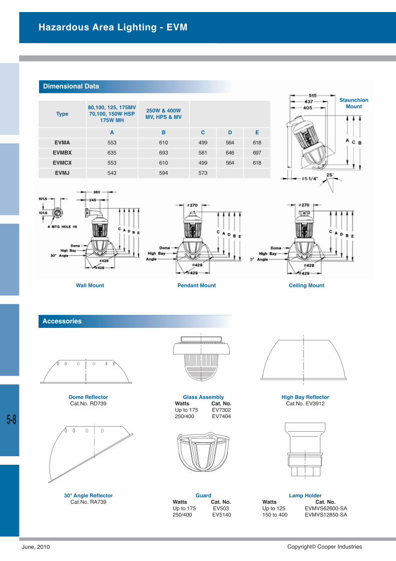
5-8
Dimensional Data
Pendant Mount Ceiling MountWall Mount
Type80,100, 125, 175MV70,100, 150W HSP
175W MH250W & 400WMV, HPS & MV
A B C D E
EVMA 553 610 499 564 618
EVMBX 635 693 581 646 697
EVMCX 553 610 499 564 618
EVMJ 543 594 573
30° Angle ReflectorCat.No. RA739
Dome ReflectorCat.No. RD739
High Bay ReflectorCat.No. EV3912
Glass AssemblyWatts Cat. No.Up to 175 EV7302250/400 EV7404
GuardWatts Cat. No.Up to 175 EV503250/400 EV5140
Lamp HolderWatts Cat. No.Up to 125 EVMVS62600-SA150 to 400 EVMVS12850-SA
Accessories
Hazardous Area Lighting - EVM
StaunchionMount
June, 2010 Copyright© Cooper Industries
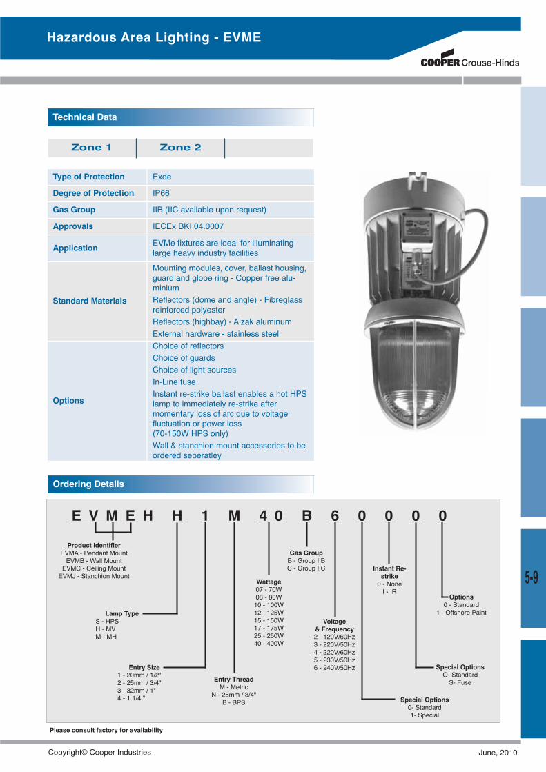
5-9
Type of Protection Exde
Degree of Protection IP66
Gas Group IIB (IIC available upon request)
Approvals IECEx BKI 04.0007
Application EVMe fixtures are ideal for illuminatinglarge heavy industry facilities
Standard Materials
Mounting modules, cover, ballast housing,guard and globe ring - Copper free alu-miniumReflectors (dome and angle) - Fibreglassreinforced polyesterReflectors (highbay) - Alzak aluminumExternal hardware - stainless steel
Options
Choice of reflectorsChoice of guardsChoice of light sourcesIn-Line fuseInstant re-strike ballast enables a hot HPSlamp to immediately re-strike aftermomentary loss of arc due to voltagefluctuation or power loss(70-150W HPS only)Wall & stanchion mount accessories to beordered seperatley
Technical Data
Zone 1 Zone 2
E V M E H H 1 M 4 0 B 6 0 0 0 0Product Identifier
EVMA - Pendant MountEVMB - Wall MountEVMC - Ceiling MountEVMJ - Stanchion Mount
Lamp TypeS - HPSH - MVM - MH
Entry Size1 - 20mm / 1/2"2 - 25mm / 3/4"3 - 32mm / 1"4 - 1 1/4 "
Entry ThreadM - Metric
N - 25mm / 3/4"B - BPS
Wattage07 - 70W08 - 80W10 - 100W12 - 125W15 - 150W17 - 175W25 - 250W40 - 400W
Voltage& Frequency2 - 120V/60Hz3 - 220V/50Hz4 - 220V/60Hz5 - 230V/50Hz6 - 240V/50Hz Special Options
O- StandardS- Fuse
Special Options0- Standard1- Special
Instant Re-strike0 - NoneI - IR
Options0 - Standard
1 - Offshore Paint
Gas GroupB - Group IIBC - Group IIC
Ordering Details
Please consult factory for availability
Hazardous Area Lighting - EVME
Copyright© Cooper Industries June, 2010
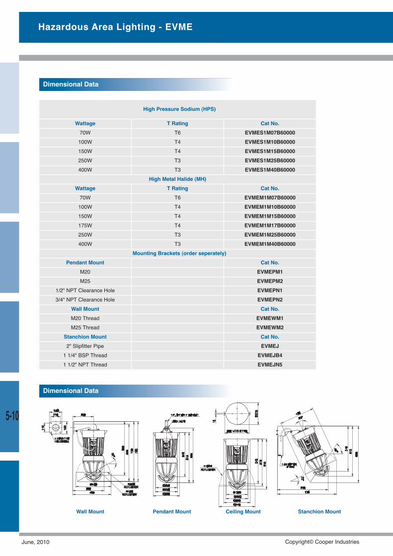
5-10
Dimensional Data
Wall Mount Pendant Mount Ceiling Mount Stanchion Mount
Hazardous Area Lighting - EVME
Dimensional Data
High Pressure Sodium (HPS)
Wattage T Rating Cat No.70W T6 EVMES1M07B60000100W T4 EVMES1M10B60000150W T4 EVMES1M15B60000250W T3 EVMES1M25B60000400W T3 EVMES1M40B60000
High Metal Halide (MH)Wattage T Rating Cat No.70W T6 EVMEM1M07B60000100W T4 EVMEM1M10B60000150W T4 EVMEM1M15B60000175W T4 EVMEM1M17B60000250W T3 EVMEM1M25B60000400W T3 EVMEM1M40B60000
Mounting Brackets (order seperately)Pendant Mount Cat No.
M20 EVMEPM1M25 EVMEPM2
1/2" NPT Clearance Hole EVMEPN13/4" NPT Clearance Hole EVMEPN2
Wall Mount Cat No.M20 Thread EVMEWM1M25 Thread EVMEWM2
Stanchion Mount Cat No.2" Slipfitter Pipe EVMEJ1 1/4" BSP Thread EVMEJB41 1/2" NPT Thread EVMEJN5
June, 2010 Copyright© Cooper Industries
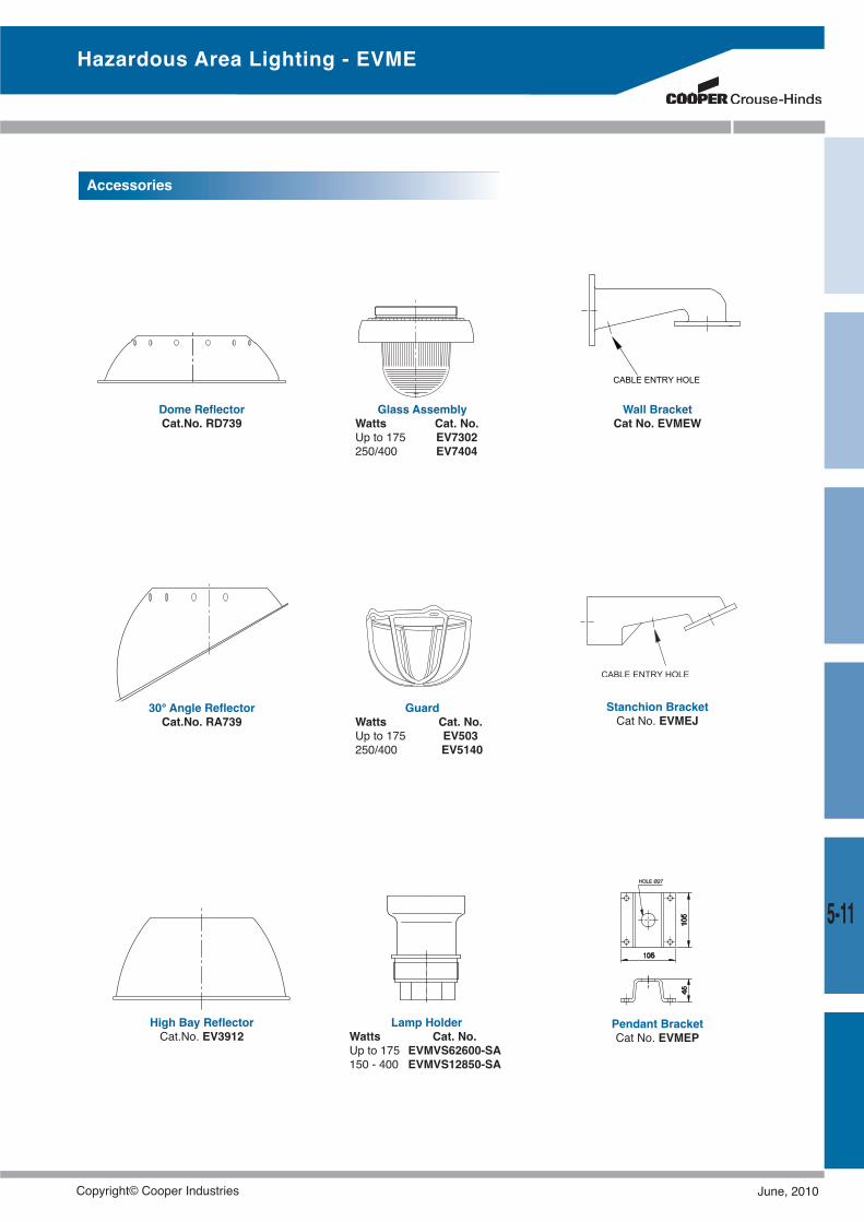
5-11
Stanchion BracketCat No. EVMEJ
Wall BracketCat No. EVMEW
30° Angle ReflectorCat.No. RA739
Dome ReflectorCat.No. RD739
High Bay ReflectorCat.No. EV3912
Glass AssemblyWatts Cat. No.Up to 175 EV7302250/400 EV7404
GuardWatts Cat. No.Up to 175 EV503250/400 EV5140
Pendant BracketCat No. EVMEP
Accessories
Lamp HolderWatts Cat. No.Up to 175 EVMVS62600-SA150 - 400 EVMVS12850-SA
Hazardous Area Lighting - EVME
Copyright© Cooper Industries June, 2010
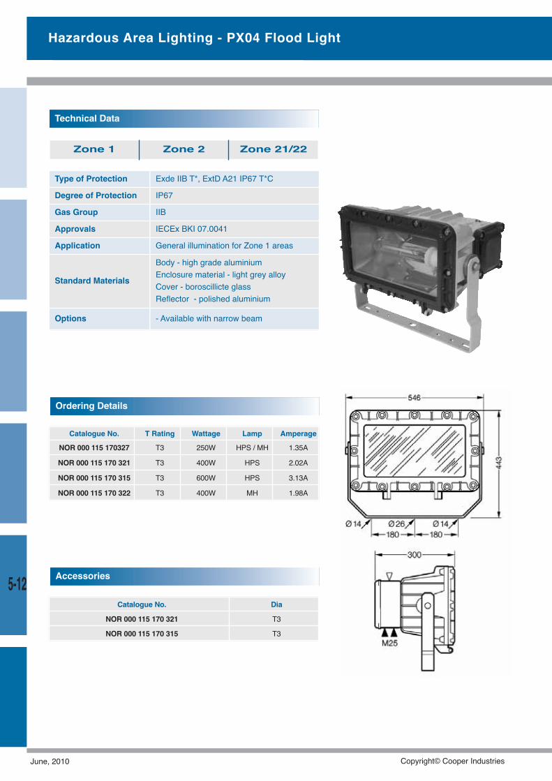
5-12
Type of Protection Exde IIB T*, ExtD A21 IP67 T*C
Degree of Protection IP67
Gas Group IIB
Approvals IECEx BKI 07.0041
Application General illumination for Zone 1 areas
Standard Materials
Body - high grade aluminiumEnclosure material - light grey alloyCover - boroscillicte glassReflector - polished aluminium
Options - Available with narrow beam
Technical Data
Zone 1 Zone 2 Zone 21/22
Catalogue No. T Rating Wattage Lamp Amperage
NOR 000 115 170327 T3 250W HPS / MH 1.35A
NOR 000 115 170 321 T3 400W HPS 2.02A
NOR 000 115 170 315 T3 600W HPS 3.13A
NOR 000 115 170 322 T3 400W MH 1.98A
Ordering Details
Catalogue No. Dia
NOR 000 115 170 321 T3
NOR 000 115 170 315 T3
Accessories
Hazardous Area Lighting - PX04 Flood Light
June, 2010 Copyright© Cooper Industries
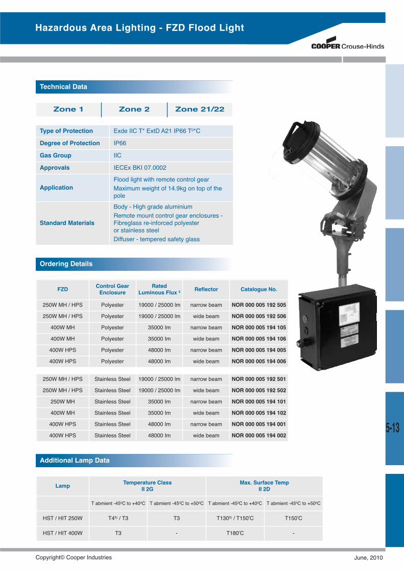
5-13
Hazardous Area Lighting - FZD Flood Light
Ordering Details
Type of Protection Exde IIC T* ExtD A21 IP66 T0*C
Degree of Protection IP66
Gas Group IIC
Approvals IECEx BKI 07.0002
ApplicationFlood light with remote control gearMaximum weight of 14.9kg on top of thepole
Standard Materials
Body - High grade aluminiumRemote mount control gear enclosures -Fibreglass re-inforced polyesteror stainless steelDiffuser - tempered safety glass
Zone 1 Zone 2 Zone 21/22
FZD Control GearEnclosure
RatedLuminous Flux 2 Reflector Catalogue No.
250W MH / HPS Polyester 19000 / 25000 lm narrow beam NOR 000 005 192 505
250W MH / HPS Polyester 19000 / 25000 lm wide beam NOR 000 005 192 506
400W MH Polyester 35000 Im narrow beam NOR 000 005 194 105
400W MH Polyester 35000 Im wide beam NOR 000 005 194 106
400W HPS Polyester 48000 Im narrow beam NOR 000 005 194 005
400W HPS Polyester 48000 Im wide beam NOR 000 005 194 006
250W MH / HPS Stainless Steel 19000 / 25000 lm narrow beam NOR 000 005 192 501
250W MH / HPS Stainless Steel 19000 / 25000 lm wide beam NOR 000 005 192 502
250W MH Stainless Steel 35000 Im narrow beam NOR 000 005 194 101
400W MH Stainless Steel 35000 Im wide beam NOR 000 005 194 102
400W HPS Stainless Steel 48000 Im narrow beam NOR 000 005 194 001
400W HPS Stainless Steel 48000 Im wide beam NOR 000 005 194 002
Additional Lamp Data
Lamp Temperature ClassII 2G
Max. Surface TempII 2D
T abmient -450C to +400C T abmient -450C to +500C T abmient -450C to +400C T abmient -450C to +500C
HST / HIT 250W T45) / T3 T3 T1305) / T1500C T1500C
HST / HIT 400W T3 - T1800C -
Technical Data
Copyright© Cooper Industries June, 2010
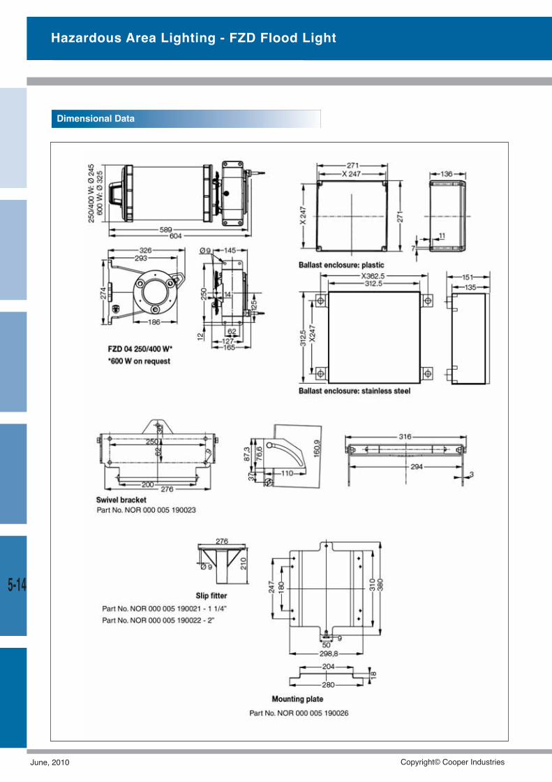
5-14
Hazardous Area Lighting - FZD Flood Light
Dimensional Data
June, 2010 Copyright© Cooper Industries
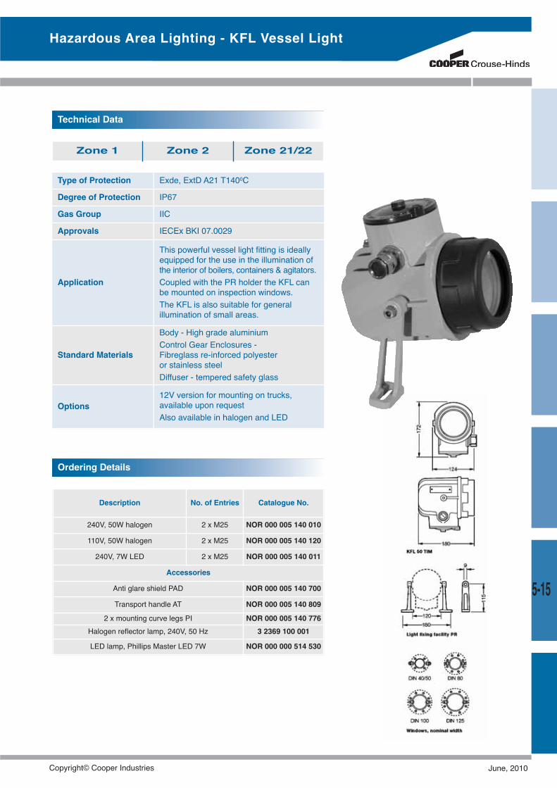
Hazardous Area Lighting - KFL Vessel Light
Type of Protection Exde, ExtD A21 T1400C
Degree of Protection IP67
Gas Group IIC
Approvals IECEx BKI 07.0029
Application
This powerful vessel light fitting is ideallyequipped for the use in the illumination ofthe interior of boilers, containers & agitators.Coupled with the PR holder the KFL canbe mounted on inspection windows.The KFL is also suitable for generalillumination of small areas.
Standard Materials
Body - High grade aluminiumControl Gear Enclosures -Fibreglass re-inforced polyesteror stainless steelDiffuser - tempered safety glass
Options12V version for mounting on trucks,available upon requestAlso available in halogen and LED
Technical Data
Zone 1 Zone 2 Zone 21/22
Ordering Details
Description No. of Entries Catalogue No.
240V, 50W halogen 2 x M25 NOR 000 005 140 010
110V, 50W halogen 2 x M25 NOR 000 005 140 120
240V, 7W LED 2 x M25 NOR 000 005 140 011
Accessories
Anti glare shield PAD NOR 000 005 140 700
Transport handle AT NOR 000 005 140 809
2 x mounting curve legs PI NOR 000 005 140 776Halogen reflector lamp, 240V, 50 Hz 3 2369 100 001
LED lamp, Phillips Master LED 7W NOR 000 000 514 530
5-15
Copyright© Cooper Industries June, 2010
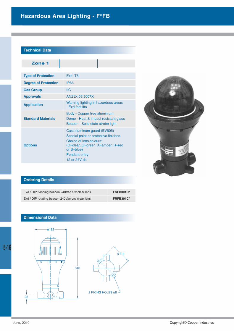
5-16
Hazardous Area Lighting - F*FB
Type of Protection Exd, T6
Degree of Protection IP66
Gas Group IIC
Approvals ANZEx 08.3007X
Application Warning lighting in hazardous areas- Exd forklifts
Standard MaterialsBody - Copper free aluminiumDome - Heat & impact resistant glassBeacon - Solid state strobe light
Options
Cast aluminum guard (EV505)Special paint or protective finishesChoice of lens colours*(C=clear, G=green, A=amber, R=redor B=blue)Pendant entry12 or 24V dc
Technical Data
Zone 1
Dimensional Data
Exd / DIP flashing beacon 240Vac c/w clear lens FSFB301C*
Exd / DIP rotating beacon 240Vac c/w clear lens FRFB301C*
Ordering Details
June, 2010 Copyright© Cooper Industries
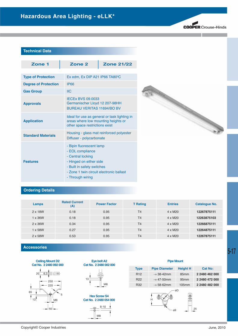
EyeboltA2CatNo. 2 2480 002 000
HexScrewS4CatNo. 2 2480 054 000
CeilingMountD2CatNo. 2 2480 092 000
Type Pipe Diameter Height H Cat No:R12 → 38-42mm 85mm 2 2480 462 000R22 → 47-50mm 95mm 2 2480 472 000R32 → 58-62mm 105mm 2 2480 482 000
Accessories
PipeMount
Type of Protection Ex edm, Ex DIP A21 IP66 TA800C
Degree of Protection IP66
Gas Group IIC
ApprovalsIECEx BVS 09.0033Germanischer Lloyd 12 207-98HHBUREAU VERITAS 11694/BO BV
ApplicationIdeal for use as general or task lighting inareas where low mounting heights orother space restrictions exist
Standard Materials Housing - glass mat reinforced polyesterDiffuser - polycarbonate
Features
- Bipin fluorescent lamp- EOL compliance- Central locking- Hinged on either side- Built in safety switches- Zone 1 twin circuit electronic ballast- Through wiring
Technical Data
Zone 1 Zone 2 Zone 21/22
Lamps Rated Current(A) Power Factor T Rating Entries Catalogue No.
2 x 18W 0.18 0.95 T4 4 x M20 12267875111
1 x 36W 0.18 0.95 T4 4 x M20 12263875103
2 x 36W 0.34 0.95 T4 4 x M20 12266875111
1 x 58W 0.27 0.95 T4 4 x M20 12264875111
2 x 58W 0.53 0.95 T4 4 x M20 12267875111
Ordering Details
Hazardous Area Lighting - eLLK*
5-17
Copyright© Cooper Industries June, 2010
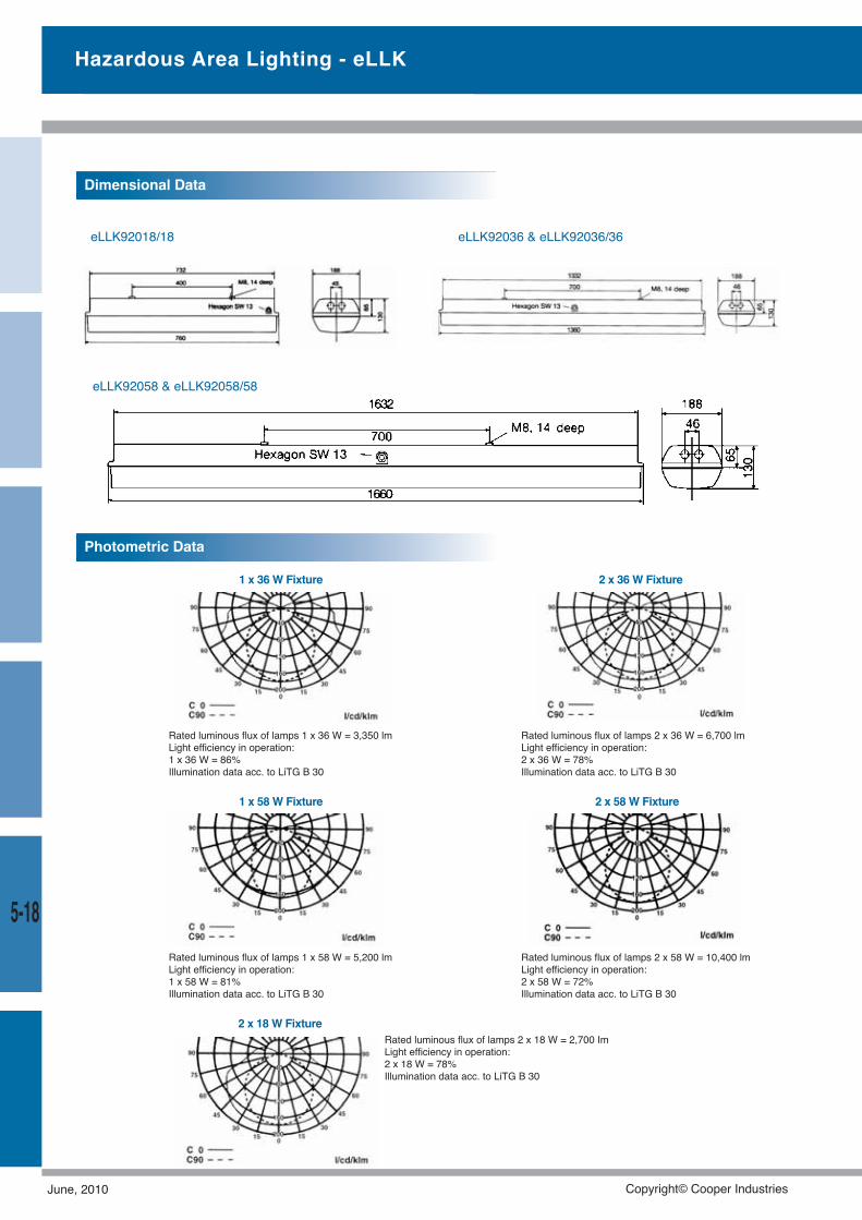
eLLK92058 & eLLK92058/58
eLLK92018/18 eLLK92036 & eLLK92036/36
Dimensional Data
1 x 36 W Fixture
Rated luminous flux of lamps 1 x 36 W = 3,350 lmLight efficiency in operation:1 x 36 W = 86%Illumination data acc. to LiTG B 30
Rated luminous flux of lamps 2 x 36 W = 6,700 lmLight efficiency in operation:2 x 36 W = 78%Illumination data acc. to LiTG B 30
2 x 36 W Fixture
1 x 58 W Fixture
Rated luminous flux of lamps 1 x 58 W = 5,200 lmLight efficiency in operation:1 x 58 W = 81%Illumination data acc. to LiTG B 30
Rated luminous flux of lamps 2 x 58 W = 10,400 lmLight efficiency in operation:2 x 58 W = 72%Illumination data acc. to LiTG B 30
2 x 58 W Fixture
Photometric Data
Hazardous Area Lighting - eLLK
Rated luminous flux of lamps 2 x 18 W = 2,700 ImLight efficiency in operation:2 x 18 W = 78%Illumination data acc. to LiTG B 30
2 x 18 W Fixture
5-18
June, 2010 Copyright© Cooper Industries
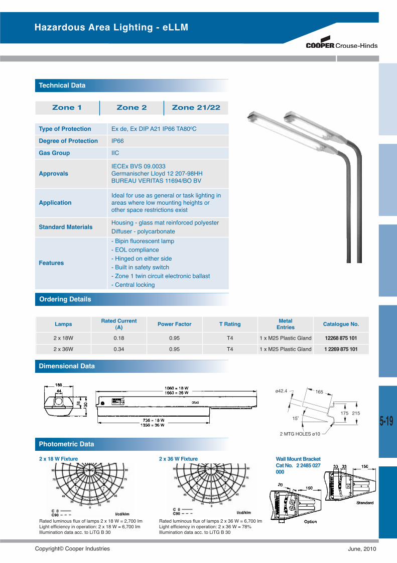
Technical Data
Zone 1 Zone 2 Zone 21/22
Ordering Details
Hazardous Area Lighting - eLLM
Dimensional Data
WallMountBracketCat No. 2 2485 027000
2 x 18 W Fixture
Rated luminous flux of lamps 2 x 18 W = 2,700 ImLight efficiency in operation: 2 x 18 W = 6,700 ImIllumination data acc. to LiTG B 30
Rated luminous flux of lamps 2 x 36 W = 6,700 lmLight efficiency in operation: 2 x 36 W = 78%Illumination data acc. to LiTG B 30
2 x 36 W Fixture
Photometric Data
Lamps Rated Current(A) Power Factor T Rating Metal
Entries Catalogue No.
2 x 18W 0.18 0.95 T4 1 x M25 Plastic Gland 12268 875 101
2 x 36W 0.34 0.95 T4 1 x M25 Plastic Gland 1 2269 875 101
Type of Protection Ex de, Ex DIP A21 IP66 TA800C
Degree of Protection IP66
Gas Group IIC
ApprovalsIECEx BVS 09.0033Germanischer Lloyd 12 207-98HHBUREAU VERITAS 11694/BO BV
ApplicationIdeal for use as general or task lighting inareas where low mounting heights orother space restrictions exist
Standard Materials Housing - glass mat reinforced polyesterDiffuser - polycarbonate
Features
- Bipin fluorescent lamp- EOL compliance- Hinged on either side- Built in safety switch- Zone 1 twin circuit electronic ballast- Central locking
5-19
Copyright© Cooper Industries June, 2010
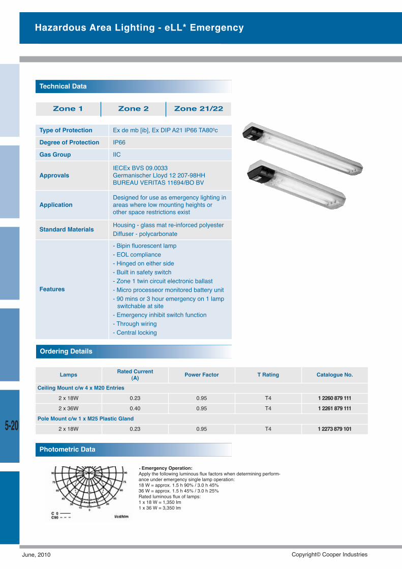
Type of Protection Ex de mb [ib], Ex DIP A21 IP66 TA800c
Degree of Protection IP66
Gas Group IIC
ApprovalsIECEx BVS 09.0033Germanischer Lloyd 12 207-98HHBUREAU VERITAS 11694/BO BV
ApplicationDesigned for use as emergency lighting inareas where low mounting heights orother space restrictions exist
Standard Materials Housing - glass mat re-inforced polyesterDiffuser - polycarbonate
Features
- Bipin fluorescent lamp- EOL compliance- Hinged on either side- Built in safety switch- Zone 1 twin circuit electronic ballast- Micro processeor monitored battery unit- 90 mins or 3 hour emergency on 1 lampswitchable at site- Emergency inhibit switch function- Through wiring- Central locking
Technical Data
Zone 1 Zone 2 Zone 21/22
Lamps Rated Current(A) Power Factor T Rating Catalogue No.
Ceiling Mount c/w 4 x M20 Entries
2 x 18W 0.23 0.95 T4 1 2260 879 111
2 x 36W 0.40 0.95 T4 1 2261 879 111
Pole Mount c/w 1 x M25 Plastic Gland
2 x 18W 0.23 0.95 T4 1 2273 879 101
Ordering Details
• Emergency Operation:Apply the following luminous flux factors when determining perform-ance under emergency single lamp operation:18 W = approx. 1.5 h 90% / 3.0 h 45%36 W = approx. 1.5 h 45% / 3.0 h 25%Rated luminous flux of lamps:1 x 18 W = 1,350 Im1 x 36 W = 3,350 lm
Photometric Data
Hazardous Area Lighting - eLL* Emergency
5-20
June, 2010 Copyright© Cooper Industries
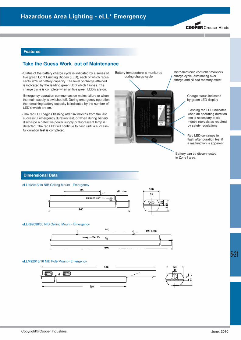
eLLk92018/18 NIB Ceiling Mount - Emergency
eLLK92036/36 NIB Ceiling Mount - Emergency
eLLM92018/18 NIB Pole Mount - Emergency
Charge status indicatedby green LED display
Microelectronic controller monitorscharge cycle, eliminating overcharge and Ni-cad memory effect
Flashing red LED indicateswhen an operating durationtest is necessary at sixmonth intervals as requiredby safety regulations
Battery can be disconnectedin Zone I area
Red LED continues toflash after duration test ifa malfunction is apparent
Battery temperature is monitoredduring charge cycle
• Status of the battery charge cycle is indicated by a series offive green Light Emitting Diodes (LED), each of which repre-sents 20% of battery capacity. The level of charge attainedis indicated by the leading green LED which flashes. Thecharge cycle is complete when all five green LED’s are on.
• Emergency operation commences on mains failure or whenthe main supply is switched off. During emergency operationthe remaining battery capacity is indicated by the number ofLED’s which are on.
• The red LED begins flashing after six months from the lastsuccessful emergency duration test, or when during batterydischarge a defective power supply or fluorescent lamp isdetected. The red LED will continue to flash until a success-ful duration test is completed.
Features
Dimensional Data
Hazardous Area Lighting - eLL* Emergency
Take the Guess Work out of Maintenance
5-21
Copyright© Cooper Industries June, 2010
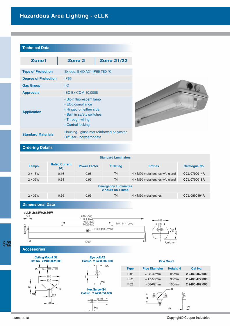
Hazardous Area Lighting - cLLK
EyeboltA2CatNo. 2 2480 002 000
HexScrewS4CatNo. 2 2480 054 000
CeilingMountD2CatNo. 2 2480 092 000
Type Pipe Diameter Height H Cat No:R12 ↓ 38-42mm 85mm 2 2480 462 000R22 ↓ 47-50mm 95mm 2 2480 472 000R32 ↓ 58-62mm 105mm 2 2480 482 000
Accessories
PipeMount
Type of Protection Ex deq, ExtD A21 IP66 T80 °C
Degree of Protection IP66
Gas Group IIC
Approvals IEC Ex CQM 10.0008
Application
- Bipin fluorescent lamp- EOL compliance- Hinged on either side- Built in safety switches- Through wiring- Central locking
Standard Materials Housing - glass mat reinforced polyesterDiffuser - polycarbonate
Technical Data
Zone1 Zone 2 Zone 21/22
Standard Luminaires
Lamps Rated Current(A) Power Factor T Rating Entries Catalogue No.
2 x 18W 0.16 0.95 T4 4 x M20 metal entries w/o gland CCL 0700014A
2 x 36W 0.34 0.95 T4 4 x M20 metal entries w/o gland CCL 0700018A
Ordering Details
Emergency Luminaires2 hours on 1 lamp
2 x 36W 0.36 0.95 T4 4 x M20 metal entries CCL 0800104A
Dimensional Data
18846
13065
1332(36W)732(18W)
700(36W)400(18W)
1360
3.5
M25
x1.5
Hexagon SW13
M8,14mm deep
cLLK 2x18W/2x36W
5-22 Unit: mm
June, 2010 Copyright© Cooper Industries
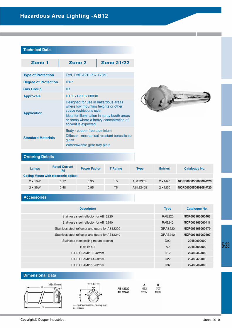
5-23
Hazardous Area Lighting -AB12
Type of Protection Exd, ExtD A21 IP67 T760C
Degree of Protection IP67
Gas Group IIB
Approvals IEC Ex BKI 07.0008X
Application
Designed for use in hazardous areaswhere low mounting heights or otherspace restrictions existIdeal for illumination in spray booth areasor areas where a heavy concentration ofsolvent is expected
Standard Materials
Body - copper free aluminiumDiffuser - mechanical resistant borosilicateglassWithdrawable gear tray plate
Technical Data
Zone 1 Zone 2 Zone 21/22
Lamps Rated Current(A) Power Factor T Rating Type Entries Catalogue No.
Ceiling Mount with electronic ballast2 x 18W 0.17 0.95 T5 AB12220E 2 x M20 NOR000005060300-M20
2 x 36W 0.48 0.95 T5 AB12240E 2 x M20 NOR000005060308-M20
Ordering Details
Descripton Type Catalogue No.
Stainless steel reflector for AB12220 RAB220 NOR003165060403
Stainless steel reflector for AB12240 RAB240 NOR003165060411
Stainless steel reflector and guard for AB12220 GRAB220 NOR003165060479
Stainless steel reflector and guard for AB12240 GRAB240 NOR003165060497
Stainless steel celling mount bracket D92 22480092000
EYE BOLT A2 22480002000
PIPE CLAMP 38-42mm R12 22480462000
PIPE CLAMP 41-50mm R22 22480472000
PIPE CLAMP 58-62mm R32 22480482000
Accessories
Dimensional Data
Copyright© Cooper Industries June, 2010
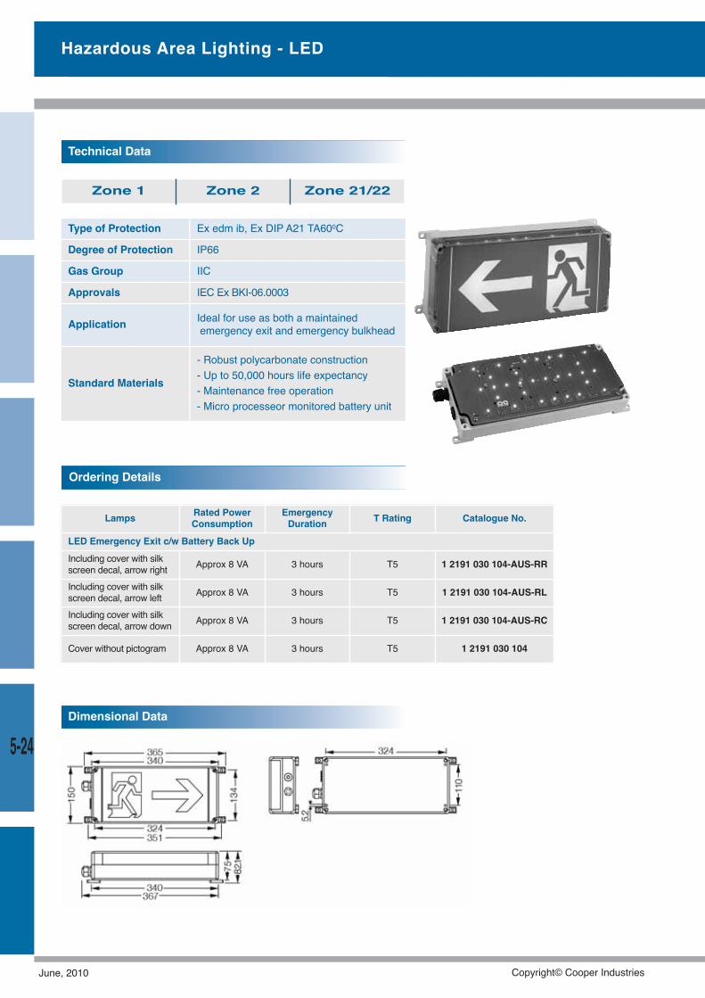
5-24
Type of Protection Ex edm ib, Ex DIP A21 TA600C
Degree of Protection IP66
Gas Group IIC
Approvals IEC Ex BKI-06.0003
Application Ideal for use as both a maintainedemergency exit and emergency bulkhead
Standard Materials
- Robust polycarbonate construction- Up to 50,000 hours life expectancy- Maintenance free operation- Micro processeor monitored battery unit
Technical Data
Zone 1 Zone 2 Zone 21/22
Lamps Rated PowerConsumption
EmergencyDuration T Rating Catalogue No.
LED Emergency Exit c/w Battery Back UpIncluding cover with silkscreen decal, arrow right Approx 8 VA 3 hours T5 1 2191 030 104-AUS-RR
Including cover with silkscreen decal, arrow left Approx 8 VA 3 hours T5 1 2191 030 104-AUS-RL
Including cover with silkscreen decal, arrow down Approx 8 VA 3 hours T5 1 2191 030 104-AUS-RC
Cover without pictogram Approx 8 VA 3 hours T5 1 2191 030 104
Ordering Details
Dimensional Data
Hazardous Area Lighting - LED
June, 2010 Copyright© Cooper Industries
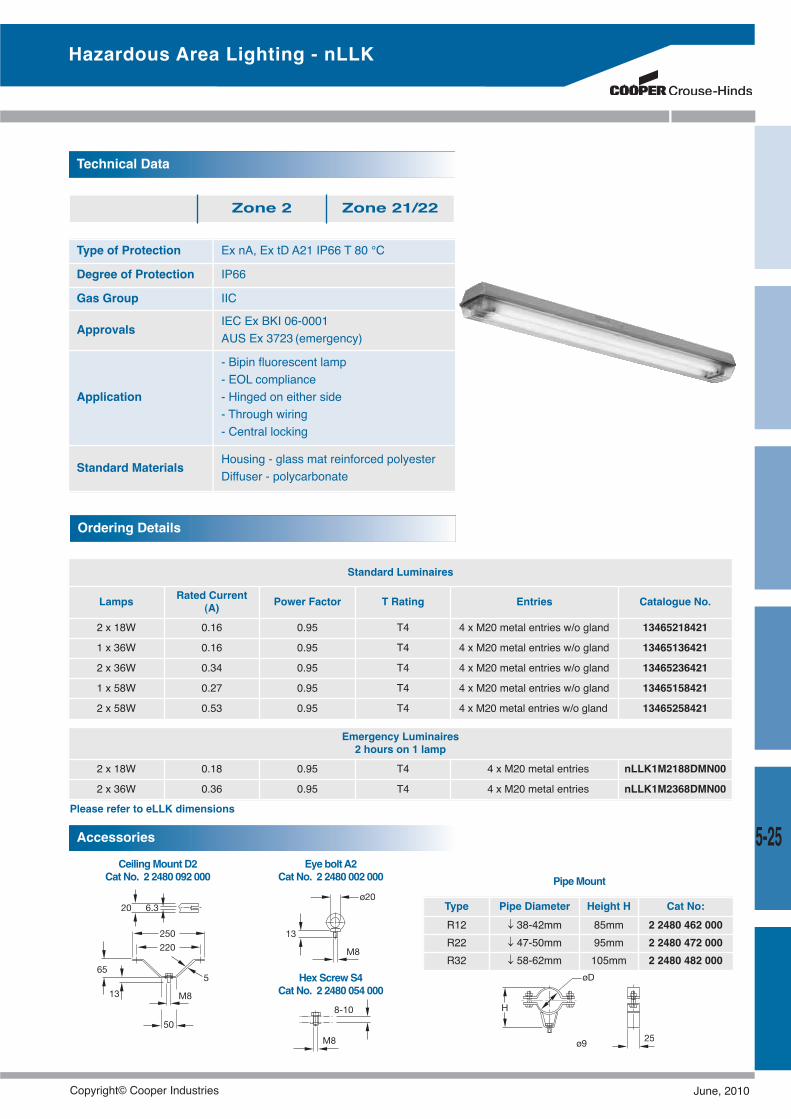
EyeboltA2CatNo. 2 2480 002 000
HexScrewS4CatNo. 2 2480 054 000
CeilingMountD2CatNo. 2 2480 092 000
Type Pipe Diameter Height H Cat No:R12 ↓ 38-42mm 85mm 2 2480 462 000R22 ↓ 47-50mm 95mm 2 2480 472 000R32 ↓ 58-62mm 105mm 2 2480 482 000
Accessories
PipeMount
Type of Protection Ex nA, Ex tD A21 IP66 T 80 °C
Degree of Protection IP66
Gas Group IIC
Approvals IEC Ex BKI 06-0001AUS Ex 3723 (emergency)
Application
- Bipin fluorescent lamp- EOL compliance- Hinged on either side- Through wiring- Central locking
Standard Materials Housing - glass mat reinforced polyesterDiffuser - polycarbonate
Technical Data
Zone 2 Zone 21/22
Standard Luminaires
Lamps Rated Current(A) Power Factor T Rating Entries Catalogue No.
2 x 18W 0.16 0.95 T4 4 x M20 metal entries w/o gland 13465218421
1 x 36W 0.16 0.95 T4 4 x M20 metal entries w/o gland 13465136421
2 x 36W 0.34 0.95 T4 4 x M20 metal entries w/o gland 13465236421
1 x 58W 0.27 0.95 T4 4 x M20 metal entries w/o gland 13465158421
2 x 58W 0.53 0.95 T4 4 x M20 metal entries w/o gland 13465258421
Ordering Details
Hazardous Area Lighting - nLLK
Emergency Luminaires2 hours on 1 lamp
2 x 18W 0.18 0.95 T4 4 x M20 metal entries nLLK1M2188DMN00
2 x 36W 0.36 0.95 T4 4 x M20 metal entries nLLK1M2368DMN00
Please refer to eLLK dimensions
5-25
Copyright© Cooper Industries June, 2010
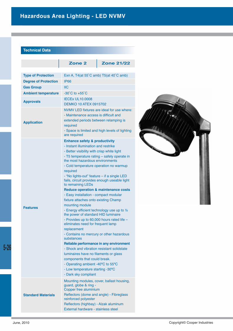
Hazardous Area Lighting - LED NVMV
Type of Protection Exn A, T4(at 55˚C amb) T5(at 40˚C amb)Degree of Protection IP66Gas Group IICAmbient temperature -30˚C to +55˚C
Approvals IECEx UL10.0008DEMKO 10 ATEX 0915702
Application
NVMV LED fixtures are ideal for use where:- Maintenance access is difficult andextended periods between relamping isrequired- Space is limited and high levels of lightingare required
Features
Enhance safety & productivity- Instant illumination and restrike- Better visibility with crisp white light- T5 temperature rating – safely operate inthe most hazardous environments- Cold temperature operation no warmuprequired- “No lights-out” feature – if a single LEDfails, circuit provides enough useable lightto remaining LEDsReduce operation & maintenance costs- Easy installation - compact modularfixture attaches onto existing Champmounting module- Energy efficient technology use up to ½the power of standard HID luminaire- Provides up to 60,000 hours rated life –eliminates need for frequent lampreplacement- Contains no mercury or other hazardoussubstancesReliable performance in any environment- Shock and vibration resistant solidstateluminaires have no filaments or glasscomponents that could break.- Operating ambient -40ºC to 55ºC- Low temperature starting -30ºC- Dark sky compliant
Standard Materials
Mounting modules, cover, ballast housing,guard, globe & ring -Copper free aluminiumReflectors (dome and angle) - Fibreglassreinforced polyesterReflectors (highbay) - Alzak aluminumExternal hardware - stainless steel
Technical Data
Zone 2 Zone 21/22
5-26
June, 2010 Copyright© Cooper Industries
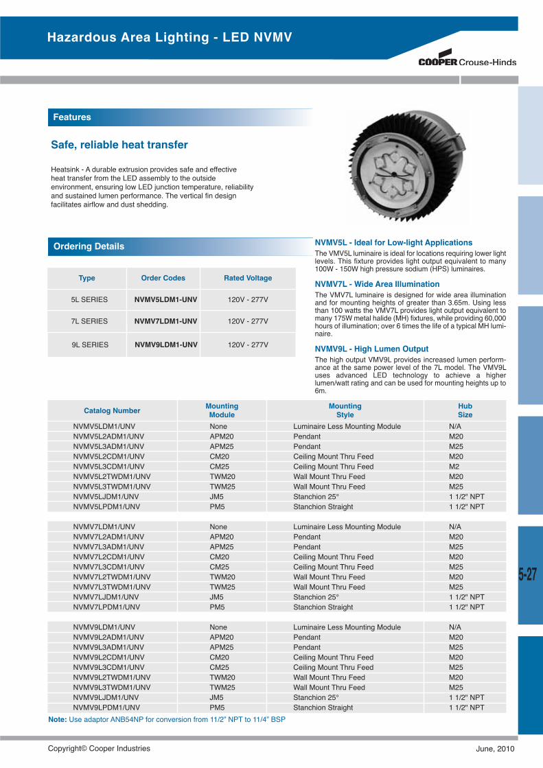
Hazardous Area Lighting - LED NVMV
Type Order Codes Rated Voltage
5L SERIES NVMV5LDM1-UNV 120V - 277V
7L SERIES NVMV7LDM1-UNV 120V - 277V
Ordering Details
9L SERIES NVMV9LDM1-UNV 120V - 277V
NVMV5L - Ideal for Low-light ApplicationsThe VMV5L luminaire is ideal for locations requiring lower lightlevels. This fixture provides light output equivalent to many100W - 150W high pressure sodium (HPS) luminaires.
NVMV7L - Wide Area IlluminationThe VMV7L luminaire is designed for wide area illuminationand for mounting heights of greater than 3.65m. Using lessthan 100 watts the VMV7L provides light output equivalent tomany 175Wmetal halide (MH) fixtures, while providing 60,000hours of illumination; over 6 times the life of a typical MH lumi-naire.
NVMV9L - High Lumen OutputThe high output VMV9L provides increased lumen perform-ance at the same power level of the 7L model. The VMV9Luses advanced LED technology to achieve a higherlumen/watt rating and can be used for mounting heights up to6m.
5-27
Features
Safe, reliable heat transfer
Heatsink - A durable extrusion provides safe and effectiveheat transfer from the LED assembly to the outsideenvironment, ensuring low LED junction temperature, reliabilityand sustained lumen performance. The vertical fin designfacilitates airflow and dust shedding.
MountingModuleCatalog Number Mounting
StyleHubSize
NVMV5LDM1/UNV None Luminaire Less Mounting Module N/ANVMV5L2ADM1/UNV APM20 Pendant M20NVMV5L3ADM1/UNV APM25 Pendant M25NVMV5L2CDM1/UNV CM20 Ceiling Mount Thru Feed M20NVMV5L3CDM1/UNV CM25 Ceiling Mount Thru Feed M2NVMV5L2TWDM1/UNV TWM20 Wall Mount Thru Feed M20NVMV5L3TWDM1/UNV TWM25 Wall Mount Thru Feed M25NVMV5LJDM1/UNV JM5 Stanchion 25° 1 1/2" NPTNVMV5LPDM1/UNV PM5 Stanchion Straight 1 1/2" NPT
NVMV7LDM1/UNV None Luminaire Less Mounting Module N/ANVMV7L2ADM1/UNV APM20 Pendant M20NVMV7L3ADM1/UNV APM25 Pendant M25NVMV7L2CDM1/UNV CM20 Ceiling Mount Thru Feed M20NVMV7L3CDM1/UNV CM25 Ceiling Mount Thru Feed M25NVMV7L2TWDM1/UNV TWM20 Wall Mount Thru Feed M20NVMV7L3TWDM1/UNV TWM25 Wall Mount Thru Feed M25NVMV7LJDM1/UNV JM5 Stanchion 25° 1 1/2" NPTNVMV7LPDM1/UNV PM5 Stanchion Straight 1 1/2" NPT
NVMV9LDM1/UNV None Luminaire Less Mounting Module N/ANVMV9L2ADM1/UNV APM20 Pendant M20NVMV9L3ADM1/UNV APM25 Pendant M25NVMV9L2CDM1/UNV CM20 Ceiling Mount Thru Feed M20NVMV9L3CDM1/UNV CM25 Ceiling Mount Thru Feed M25NVMV9L2TWDM1/UNV TWM20 Wall Mount Thru Feed M20NVMV9L3TWDM1/UNV TWM25 Wall Mount Thru Feed M25NVMV9LJDM1/UNV JM5 Stanchion 25° 1 1/2" NPTNVMV9LPDM1/UNV PM5 Stanchion Straight 1 1/2" NPT
Note: Use adaptor ANB54NP for conversion from 11/2” NPT to 11/4” BSP
Copyright© Cooper Industries June, 2010
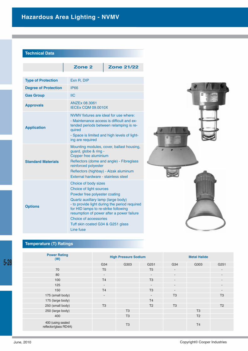
Type of Protection Exn R, DIP
Degree of Protection IP66
Gas Group IIC
Approvals ANZEx 08.3061IECEx CQM 09.0010X
Application
NVMV fixtures are ideal for use where:- Maintenance access is difficult and ex-tended periods between relamping is re-quired- Space is limited and high levels of light-ing are required
Standard Materials
Mounting modules, cover, ballast housing,guard, globe & ring -Copper free aluminiumReflectors (dome and angle) - Fibreglassreinforced polyesterReflectors (highbay) - Alzak aluminumExternal hardware - stainless steel
Options
Choice of body sizesChoice of light sourcesPowder free polyester coatingQuartz auxillary lamp (large body)- to provide light during the period requiredfor HID lamps to re-strike followingresumption of power after a power failureChoice of accessoriesTuff skin coated G34 & G251 glassLine fuse
Technical Data
Zone 2 Zone 21/22
Power Rating(W) High Pressure Sodium Metal Halide
G34 G303 G251 G34 G303 G25170 T5 T5 - -80 - - - -100 T4 T3 - -125 - - - -150 T4 T3 - -
175 (small body) - - T3 T3175 (large body) T4250 (small body) T3 T2 T3 T2250 (large body) T3 T3
400 T3 T2
400 (using sealedreflector/glass RD4A) T3 T4
Temperature (T) Ratings
Hazardous Area Lighting - NVMV
5-28
June, 2010 Copyright© Cooper Industries
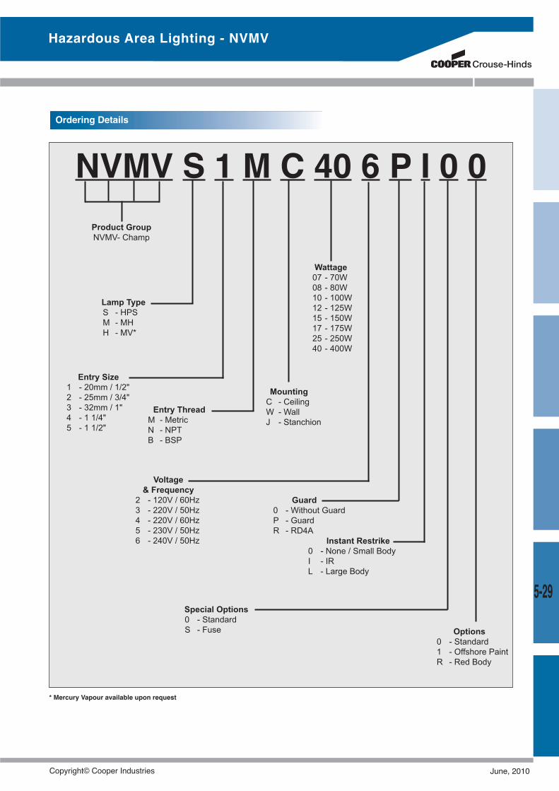
Hazardous Area Lighting - NVMV
5-29
NVMV S 1 M C 40 6 P I 0 0Product GroupNVMV- Champ
Lamp TypeS - HPSM - MHH - MV*
Entry Size1 - 20mm / 1/2"2 - 25mm / 3/4"3 - 32mm / 1"4 - 1 1/4"5 - 1 1/2"
Entry ThreadM - MetricN - NPTB - BSP
MountingC - CeilingW - WallJ - Stanchion
Voltage& Frequency
2 - 120V / 60Hz3 - 220V / 50Hz4 - 220V / 60Hz5 - 230V / 50Hz6 - 240V / 50Hz
Special Options0 - StandardS - Fuse
Guard0 - Without GuardP - GuardR - RD4A
Instant Restrike0 - None / Small BodyI - IRL - Large Body
Options0 - Standard1 - Offshore PaintR - Red Body
Wattage07 - 70W08 - 80W10 - 100W12 - 125W15 - 150W17 - 175W25 - 250W40 - 400W
Ordering Details
* Mercury Vapour available upon request
Copyright© Cooper Industries June, 2010
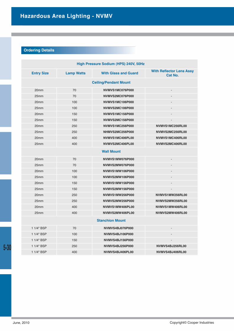
High Pressure Sodium (HPS) 240V, 50Hz
Entry Size Lamp Watts With Glass and Guard With Reflector Lens AssyCat No.
Ceiling/Pendant Mount
20mm 70 NVMVS1MC076P000 -
25mm 70 NVMVS2MC076P000 -
20mm 100 NVMVS1MC106P000 -
25mm 100 NVMVS2MC106P000 -
20mm 150 NVMVS1MC156P000 -
25mm 150 NVMVS2MC156P000 -
20mm 250 NVMVS1MC256P000 NVMVS1MC256RL00
25mm 250 NHMVS2MC256P000 NVMVS2MC256RL00
20mm 400 NVMVS1MC406PL00 NVMVS1MC406RL00
25mm 400 NVMVS2MC406PL00 NVMVS2MC406RL00
Wall Mount
20mm 70 NVMVS1MW076P000 -
25mm 70 NVMVS2MW076P000 -
20mm 100 NVMVS1MW106P000 -
25mm 100 NVMVS2MW106P000 -
20mm 150 NVMVS1MW156P000 -
25mm 150 NVMVS2MW156P000 -
20mm 250 NVMVS1MW256P000 NVMVS1MW256RL00
25mm 250 NVMVS2MW256P000 NVMVS2MW256RL00
20mm 400 NVMVS1MW406PL00 NVMVS1MW406RL00
25mm 400 NVMVS2MW406PL00 NVMVS2MW406RL00
Stanchion Mount
1 1/4" BSP 70 NVMVS4BJ076P000 -
1 1/4" BSP 100 NVMVS4BJ106P000 -
1 1/4" BSP 150 NVMVS4BJ156P000 -
1 1/4" BSP 250 NVMVS4BJ256P000 NVMVS4BJ256RL00
1 1/4" BSP 400 NVMVS4BJ406PL00 NVMVS4BJ406RL00
Ordering Details
Hazardous Area Lighting - NVMV
5-30
June, 2010 Copyright© Cooper Industries
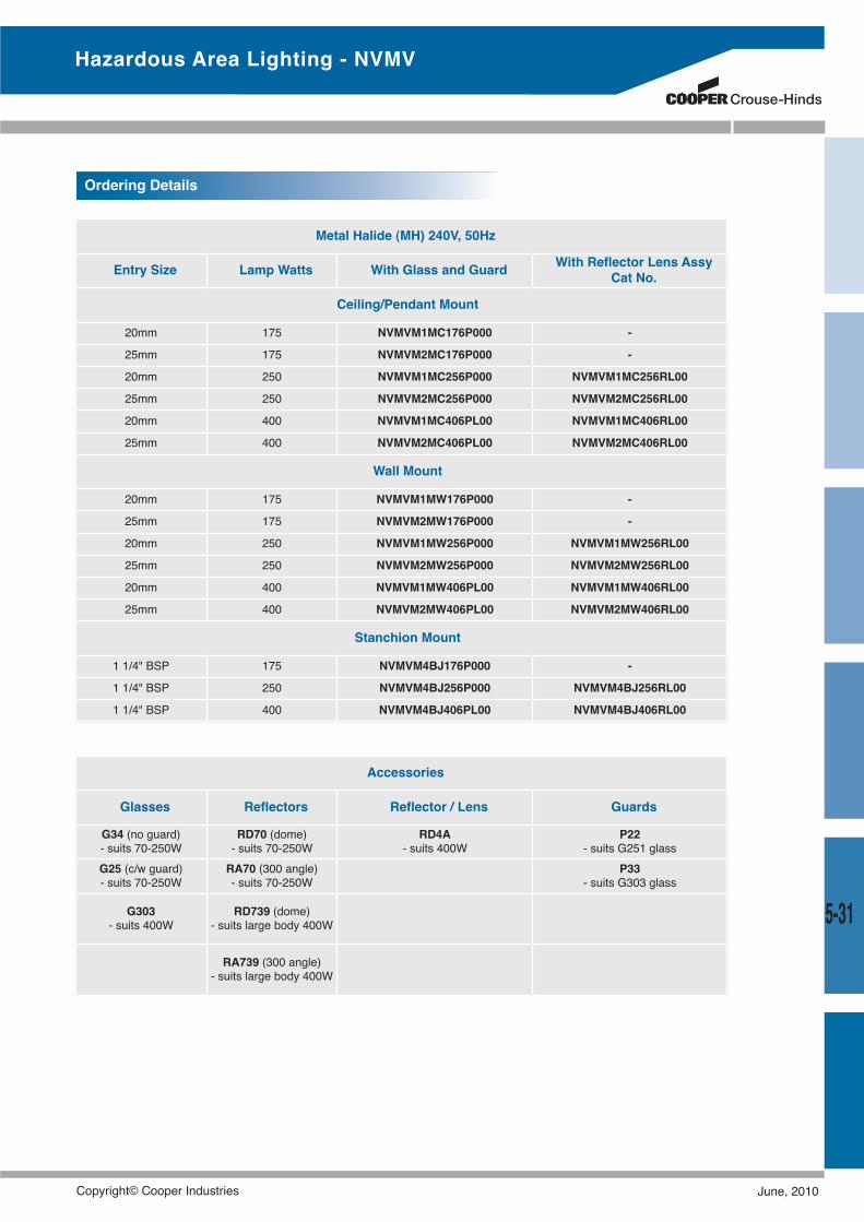
Hazardous Area Lighting - NVMV
5-31
Metal Halide (MH) 240V, 50Hz
Entry Size Lamp Watts With Glass and Guard With Reflector Lens AssyCat No.
Ceiling/Pendant Mount
20mm 175 NVMVM1MC176P000 -
25mm 175 NVMVM2MC176P000 -
20mm 250 NVMVM1MC256P000 NVMVM1MC256RL00
25mm 250 NVMVM2MC256P000 NVMVM2MC256RL00
20mm 400 NVMVM1MC406PL00 NVMVM1MC406RL00
25mm 400 NVMVM2MC406PL00 NVMVM2MC406RL00
Wall Mount
20mm 175 NVMVM1MW176P000 -
25mm 175 NVMVM2MW176P000 -
20mm 250 NVMVM1MW256P000 NVMVM1MW256RL00
25mm 250 NVMVM2MW256P000 NVMVM2MW256RL00
20mm 400 NVMVM1MW406PL00 NVMVM1MW406RL00
25mm 400 NVMVM2MW406PL00 NVMVM2MW406RL00
Stanchion Mount
1 1/4" BSP 175 NVMVM4BJ176P000 -
1 1/4" BSP 250 NVMVM4BJ256P000 NVMVM4BJ256RL00
1 1/4" BSP 400 NVMVM4BJ406PL00 NVMVM4BJ406RL00
Ordering Details
Accessories
Glasses Reflectors Reflector / Lens Guards
G34 (no guard)- suits 70-250W
RD70 (dome)- suits 70-250W
RD4A- suits 400W
P22- suits G251 glass
G25 (c/w guard)- suits 70-250W
RA70 (300 angle)- suits 70-250W
P33- suits G303 glass
G303- suits 400W
RD739 (dome)- suits large body 400W
RA739 (300 angle)- suits large body 400W
Copyright© Cooper Industries June, 2010
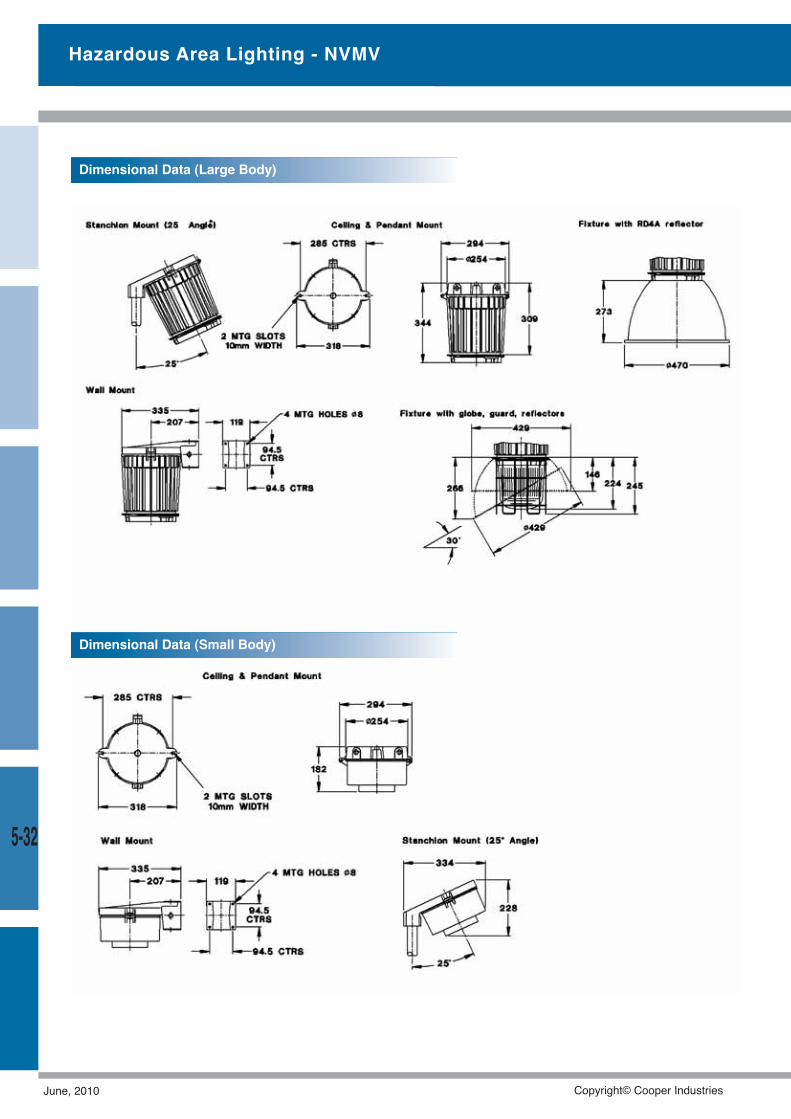
Hazardous Area Lighting - NVMV
5-32
Dimensional Data (Large Body)
Dimensional Data (Small Body)
June, 2010 Copyright© Cooper Industries
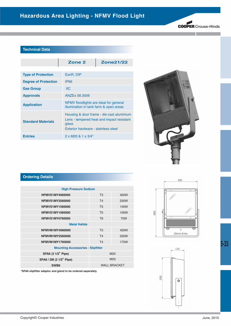
Type of Protection ExnR, DIP
Degree of Protection IP66
Gas Group IIC
Approvals ANZEx 08.3056
Application NFMV floodlights are ideal for generalillumination in tank farm & open areas
Standard Materials
Housing & door frame - die cast aluminiumLens - tempered heat and impact resistantglassExterior hardware - stainless steel
Entries 2 x M20 & 1 x 3/4”
Technical Data
Zone 2 Zone21/22
High Pressure Sodium
NFMVS1MY4060000 T3 400W
NFMVS1MY2560000 T4 250W
NFMVS1MY1560000 T5 150W
NFMVS1MY1060000 T5 100W
NFMVS1MY0760000 T6 70W
Metal Halide
NFMVM1MY4060000 T3 400W
NFMVM1MY2560000 T4 250W
NFMVM1MY1760000 T4 175W
Mounting Accessories - Slipfitter
SFA6 (2 1/2" Pipe) M20
SFA6 / 2M (2 1/2" Pipe)
SWB6
Ordering Details
M25
WALL BRACKET*SFA6 slipfitter adaptor and gland to be ordered seperately
Hazardous Area Lighting - NFMV Flood Light
5-33
Copyright© Cooper Industries June, 2010
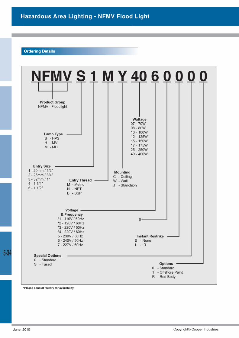
Hazardous Area Lighting - NFMV Flood Light
5-34
NFMV S 1 M Y 40 6 0 0 0 0Product GroupNFMV - Floodlight
Lamp TypeS - HPSH - MVM - MH
Entry Size1 - 20mm / 1/2"2 - 25mm / 3/4"3 - 32mm / 1"4 - 1 1/4"5 - 1 1/2"
Entry ThreadM - MetricN - NPTB - BSP
MountingC - CeilingW - WallJ - Stanchion
Voltage& Frequency
*1 - 110V / 60Hz*2 - 120V / 60Hz*3 - 220V / 50Hz*4 - 220V / 60Hz5 - 230V / 50Hz6 - 240V / 50Hz7 - 227V / 60Hz
Special Options0 - StandardS - Fused
0
Instant Restrike0 - NoneI - IR
Options0 - Standard1 - Offshore PaintR - Red Body
Wattage07 - 70W08 - 80W10 - 100W12 - 125W15 - 150W17 - 175W25 - 250W40 - 400W
Ordering Details
*Please consult factory for availability
June, 2010 Copyright© Cooper Industries
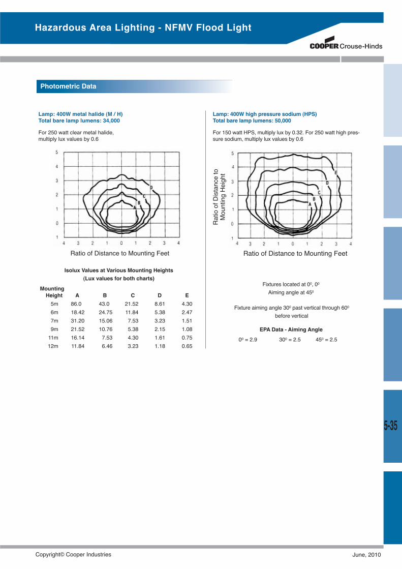
5-35
Hazardous Area Lighting - NFMV Flood Light
Lamp: 400W high pressure sodium (HPS)Total bare lamp lumens: 50,000
For 150 watt HPS, multiply lux by 0.32. For 250 watt high pres-sure sodium, multiply lux values by 0.6
Lamp: 400W metal halide (M / H)Total bare lamp lumens: 34,000
For 250 watt clear metal halide,multiply lux values by 0.6
Isolux Values at Various Mounting Heights(Lux values for both charts)
MountingHeight A B C D E5m 86.0 43.0 21.52 8.61 4.306m 18.42 24.75 11.84 5.38 2.477m 31.20 15.06 7.53 3.23 1.519m 21.52 10.76 5.38 2.15 1.0811m 16.14 7.53 4.30 1.61 0.7512m 11.84 6.46 3.23 1.18 0.65
Ratio of Distance to Mounting Feet Ratio of Distance to Mounting Feet
Fixtures located at 00, 00Aiming angle at 450
Fixture aiming angle 300 past vertical through 600before vertical
00 = 2.9 300 = 2.5 450 = 2.5
EPA Data - Aiming Angle
RatioofDistanceto
MountingHeight
Photometric Data
Copyright© Cooper Industries June, 2010
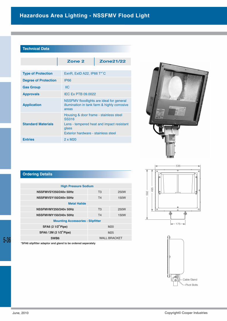
Hazardous Area Lighting - NSSFMV Flood Light
5-36
Type of Protection ExnR, ExtD A22, IP66 T*˚C
Degree of Protection IP66
Gas Group IIC
Approvals IEC Ex PTB 09.0022
ApplicationNSSFMV floodlights are ideal for generalillumination in tank farm & highly corrosiveareas
Standard Materials
Housing & door frame - stainless steelSS316Lens - tempered heat and impact resistantglassExterior hardware - stainless steel
Entries 2 x M20
Technical Data
Zone 2 Zone21/22
High Pressure Sodium
NSSFMVSY250/240v 50Hz T3 250W
NSSFMVSY150/240v 50Hz T4 150W
Metal Halide
NSSFMVMY250/240v 50Hz T3 250W
NSSFMVMY150/240v 50Hz T4 150W
Mounting Accessories - Slipfitter
SFA6 (2 1/2"Pipe) M20
SFA6 / 2M (2 1/2"Pipe) M25WALL BRACKETSWB6
Ordering Details
495
592
175
Cable Gland
Pivot Bolts
536
*SFA6 slipfitter adaptor and gland to be ordered seperately
June, 2010 Copyright© Cooper Industries
5-37
Copyright© Cooper Industries June, 2010
Be it in a Gaseous or Dusty environment, we have the solutionfor your connectivity.
From switching main current (AC3) to instrumentation we willconnect you with our GHG5, FSQA, FNO and our very own Ex-Link series.
Crouse-Hinds, through years of research and developmenthave created sophisticated engineered products that are simpleto use for our customers.
Plugs & Receptacles
June, 2010 Copyright© Cooper Industries
6-1
Plugs & Receptacles
Plugs & ReceptaclesFSQA - Exd, DIP, T6........................................................6-2PP - Exd, DIP, T6 ............................................................6-2FNO - Exd, DIP, T6..........................................................6-3PP - Exd, DIP, T6 ............................................................6-4GHG - Ex de, T6, Ex tD ..................................................6-6GHG Ex-Link ..................................................................6-7
Copyright© Cooper Industries June, 2010
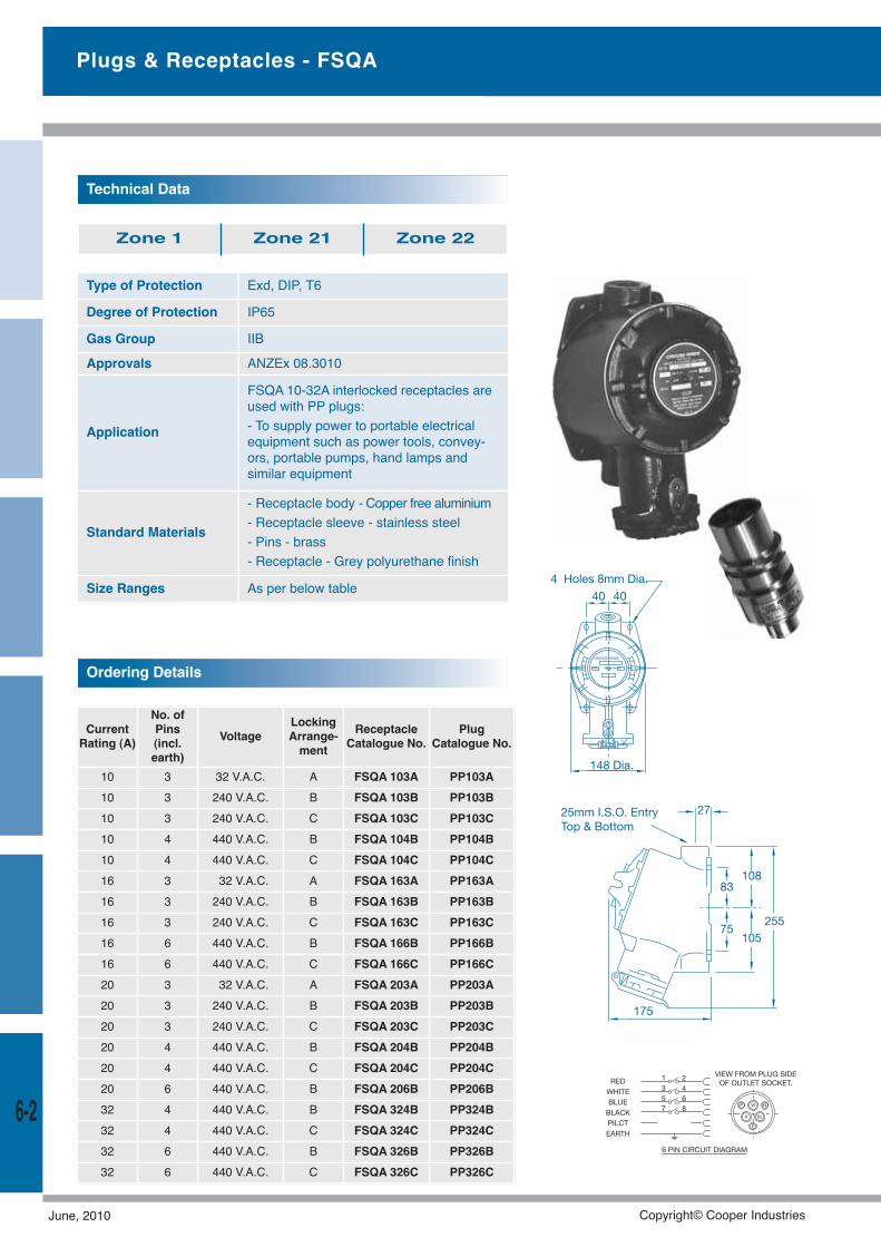
Plugs & Receptacles - FSQA
Type of Protection Exd, DIP, T6
Degree of Protection IP65
Gas Group IIB
Approvals ANZEx 08.3010
Application
FSQA 10-32A interlocked receptacles areused with PP plugs:- To supply power to portable electricalequipment such as power tools, convey-ors, portable pumps, hand lamps andsimilar equipment
Standard Materials
- Receptacle body - Copper free aluminium- Receptacle sleeve - stainless steel- Pins - brass- Receptacle - Grey polyurethane finish
Size Ranges As per below table
Technical Data
Zone 1 Zone 21 Zone 22
CurrentRating (A)
No. ofPins(incl.earth)
VoltageLockingArrange-ment
ReceptacleCatalogue No.
PlugCatalogue No.
10 3 32 V.A.C. A FSQA 103A PP103A10 3 240 V.A.C. B FSQA 103B PP103B10 3 240 V.A.C. C FSQA 103C PP103C10 4 440 V.A.C. B FSQA 104B PP104B10 4 440 V.A.C. C FSQA 104C PP104C16 3 32 V.A.C. A FSQA 163A PP163A16 3 240 V.A.C. B FSQA 163B PP163B16 3 240 V.A.C. C FSQA 163C PP163C16 6 440 V.A.C. B FSQA 166B PP166B16 6 440 V.A.C. C FSQA 166C PP166C20 3 32 V.A.C. A FSQA 203A PP203A20 3 240 V.A.C. B FSQA 203B PP203B20 3 240 V.A.C. C FSQA 203C PP203C20 4 440 V.A.C. B FSQA 204B PP204B20 4 440 V.A.C. C FSQA 204C PP204C20 6 440 V.A.C. B FSQA 206B PP206B32 4 440 V.A.C. B FSQA 324B PP324B32 4 440 V.A.C. C FSQA 324C PP324C32 6 440 V.A.C. B FSQA 326B PP326B32 6 440 V.A.C. C FSQA 326C PP326C
Ordering Details
6-2
June, 2010 Copyright© Cooper Industries
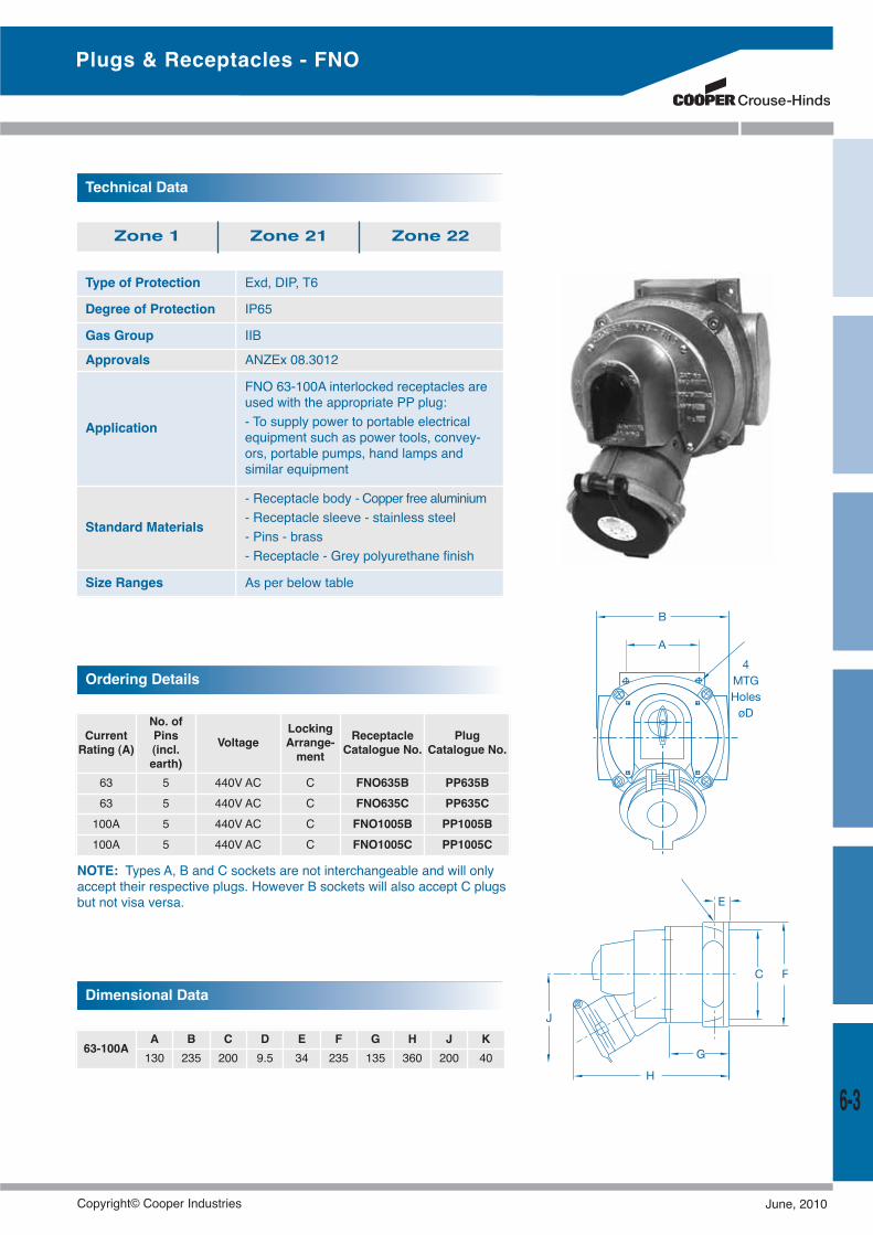
NOTE: Types A, B and C sockets are not interchangeable and will onlyaccept their respective plugs. However B sockets will also accept C plugsbut not visa versa.
Type of Protection Exd, DIP, T6
Degree of Protection IP65
Gas Group IIB
Approvals ANZEx 08.3012
Application
FNO 63-100A interlocked receptacles areused with the appropriate PP plug:- To supply power to portable electricalequipment such as power tools, convey-ors, portable pumps, hand lamps andsimilar equipment
Standard Materials
- Receptacle body - Copper free aluminium- Receptacle sleeve - stainless steel- Pins - brass- Receptacle - Grey polyurethane finish
Size Ranges As per below table
Technical Data
Zone 1 Zone 21 Zone 22
CurrentRating (A)
No. ofPins(incl.earth)
VoltageLockingArrange-ment
ReceptacleCatalogue No.
PlugCatalogue No.
63 5 440V AC C FNO635B PP635B63 5 440V AC C FNO635C PP635C100A 5 440V AC C FNO1005B PP1005B100A 5 440V AC C FNO1005C PP1005C
Ordering Details
Dimensional Data
63-100AA B C D E F G H J K130 235 200 9.5 34 235 135 360 200 40
6-3
Plugs & Receptacles - FNO
Copyright© Cooper Industries June, 2010
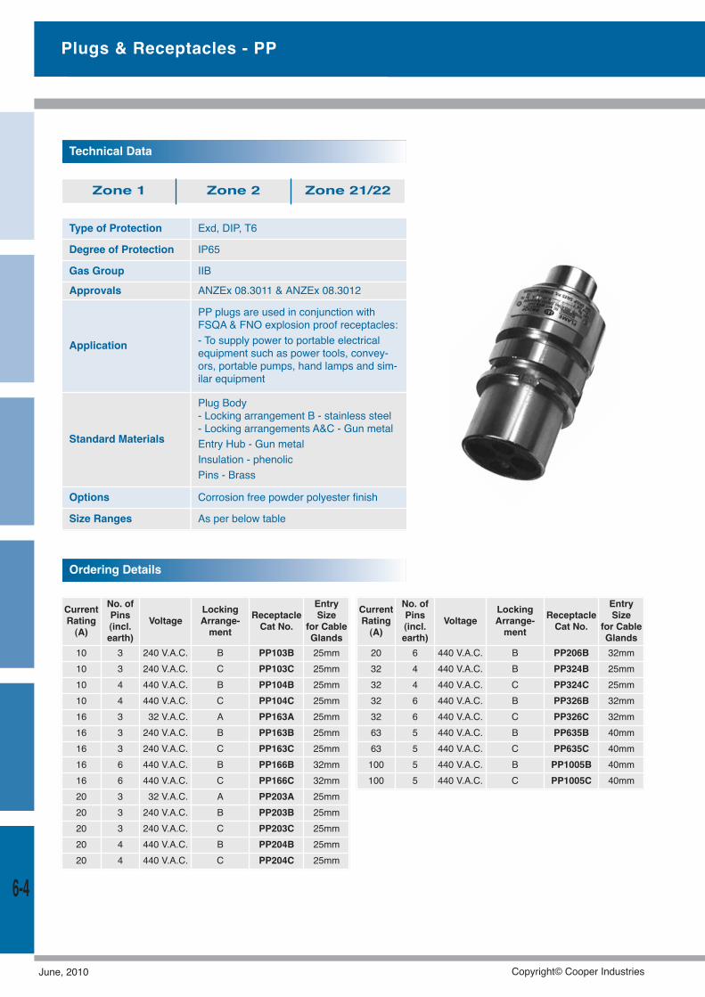
Type of Protection Exd, DIP, T6
Degree of Protection IP65
Gas Group IIB
Approvals ANZEx 08.3011 & ANZEx 08.3012
Application
PP plugs are used in conjunction withFSQA & FNO explosion proof receptacles:- To supply power to portable electricalequipment such as power tools, convey-ors, portable pumps, hand lamps and sim-ilar equipment
Standard Materials
Plug Body- Locking arrangement B - stainless steel- Locking arrangements A&C - Gun metalEntry Hub - Gun metalInsulation - phenolicPins - Brass
Options Corrosion free powder polyester finish
Size Ranges As per below table
Technical Data
Zone 1 Zone 2 Zone 21/22
CurrentRating(A)
No. ofPins(incl.earth)
VoltageLockingArrange-ment
ReceptacleCat No.
EntrySize
for CableGlands
10 3 240 V.A.C. B PP103B 25mm10 3 240 V.A.C. C PP103C 25mm10 4 440 V.A.C. B PP104B 25mm10 4 440 V.A.C. C PP104C 25mm16 3 32 V.A.C. A PP163A 25mm16 3 240 V.A.C. B PP163B 25mm16 3 240 V.A.C. C PP163C 25mm16 6 440 V.A.C. B PP166B 32mm16 6 440 V.A.C. C PP166C 32mm20 3 32 V.A.C. A PP203A 25mm20 3 240 V.A.C. B PP203B 25mm20 3 240 V.A.C. C PP203C 25mm20 4 440 V.A.C. B PP204B 25mm20 4 440 V.A.C. C PP204C 25mm
Ordering Details
CurrentRating(A)
No. ofPins(incl.earth)
VoltageLockingArrange-ment
ReceptacleCat No.
EntrySize
for CableGlands
20 6 440 V.A.C. B PP206B 32mm32 4 440 V.A.C. B PP324B 25mm32 4 440 V.A.C. C PP324C 25mm32 6 440 V.A.C. B PP326B 32mm32 6 440 V.A.C. C PP326C 32mm63 5 440 V.A.C. B PP635B 40mm63 5 440 V.A.C. C PP635C 40mm100 5 440 V.A.C. B PP1005B 40mm100 5 440 V.A.C. C PP1005C 40mm
Plugs & Receptacles - PP
6-4
June, 2010 Copyright© Cooper Industries
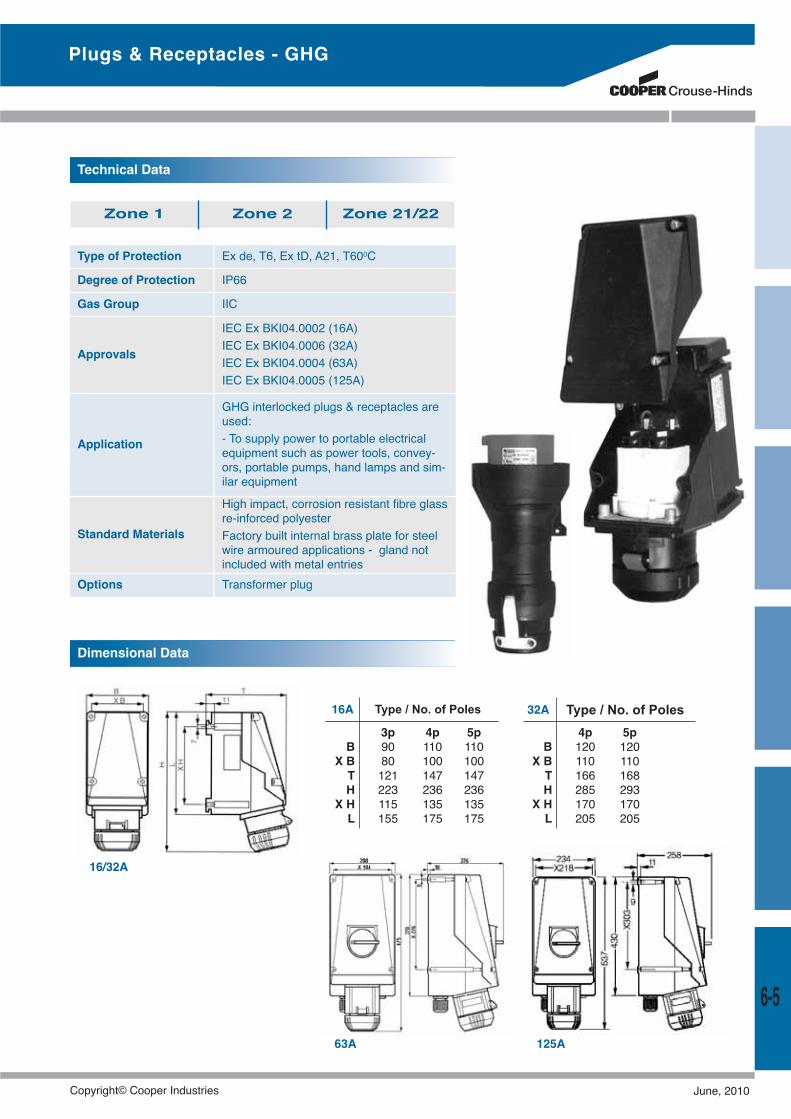
Type of Protection Ex de, T6, Ex tD, A21, T600C
Degree of Protection IP66
Gas Group IIC
Approvals
IEC Ex BKI04.0002 (16A)IEC Ex BKI04.0006 (32A)IEC Ex BKI04.0004 (63A)IEC Ex BKI04.0005 (125A)
Application
GHG interlocked plugs & receptacles areused:- To supply power to portable electricalequipment such as power tools, convey-ors, portable pumps, hand lamps and sim-ilar equipment
Standard Materials
High impact, corrosion resistant fibre glassre-inforced polyesterFactory built internal brass plate for steelwire armoured applications - gland notincluded with metal entries
Options Transformer plug
Technical Data
Dimensional Data
3p 4p 5pB 90 110 110
X B 80 100 100T 121 147 147H 223 236 236
X H 115 135 135L 155 175 175
Type / No. of Poles
4p 5pB 120 120
X B 110 110T 166 168H 285 293
X H 170 170L 205 205
Type / No. of Poles16A 32A
Plugs & Receptacles - GHG
125A
16/32A
63A
Zone 1 Zone 2 Zone 21/22
6-5
Copyright© Cooper Industries June, 2010
Ordering Details
Switch socket 16A, 2P, 24Vac/dc, 2 x M20 2 x 1.5 - 4 mm2 GHG5134200R0001
Plug, 16A, 2P, 24V ac/dc, 9-17mm 1.0 - 4 mm2 GHG5422200V0000
Switch socket 16A, 3P, 24Vac/dc, 2 x M20 2 x 1.5 - 4 mm2 GHG5134312R0001
Plug, 16A, 3P, 24V ac/dc, 9-17mm 1.0 - 4 mm2 GHG5422312V0000
Switch socket 16A, 3P, 110-130Vac, 2 x M20 metal entries 2 x 1 - 4 mm2 GHG5114304R3001
Switch coupler, 16A, 3P, 110-130Vac, 8-19mm 2 x 1 - 4 mm2 GHG5113304R0001
Plug, 16A, 3P, 110-130Vac, 8-19mm 1 x 1 - 2.5 mm2 GHG5117304R0001
Switch socket 16A, 4P, 200-250Vac, 2 x M20 metal entries 2 x 1 - 4 mm2 GHG5114409R3001
Switch coupler, 16A, 4P, 200-250Vac, 8-21mm 2 x 1 - 4 mm2 GHG5113409R0001
Plug, 16A, 4P, 200-250Vac, 8-21mm 1 x 1 - 2.5 mm2 GHG5117409R0001
Switch socket 16A, 4P, 380-415Vac, 2 x M20 metal entries 2 x 1 - 4 mm2 GHG5114406R3001
Switch coupler, 16A, 4P, 380-415Vac, 8-21mm 2 x 1 - 4 mm2 GHG5113406R0001
Plug, 16A, 4P, 380-415Vac, 8-21mm 1 x 1 - 2.5 mm2 GHG5117406R0001
Switch socket 16A, 5P, 380-415Vac, 2 x M20 metal entries 2 x 1 - 4 mm2 GHG5114506R3001
Switch coupler, 16A, 5P, 380-415Vac, 12-21mm 2 x 1 - 4 mm2 GHG5113506R0001
Plug, 16A, 4P, 380-415Vac, 12-21mm 1 x 1 - 2.5 mm2 GHG5117506R0001
Switch socket 32A, 5P, 380-415Vac, 2 x M32 metal entries 2 x 4 - 10 mm2 GHG5124506R3001
Switch coupler, 32A, 5P, 380-415Vac, 17-28mm 2 x 4 - 10 mm2 GHG5123506R0001
Plug, 32A, 5P, 380-415Vac, 17-28mm 1 x 1 - 6 mm2 GHG5127506R0001
Switch socket 63A, 4P, 380-415Vac, 2 x M40 metal entries 2 x 4 - 25 mm2 GHG5144406R3001
Plug, 63A, 4P, 380-415Vac, 19-34mm 1 x 4 - 16 mm2 GHG5147406R0001
Switch socket 63A, 5P, 380-415Vac, 2 x M40 metal entries 2 x 4 - 25 mm2 GHG5144506R3001
Plug, 63A, 5P, 380-415Vac, 19-34mm 1 x 4 - 16 mm2 GHG5147506R0001
Description Terminal Capacity Catalogue No.
Switch socket 16A, 3P, 200-250Vac, 2 x M20 metal entries 2 x 1 - 4 mm2 GHG5114306R3001
Switch coupler, 16A, 3P, 200-250Vac, 8-19mm 2 x 1 - 4 mm2 GHG5113306R0001
Plug, 16A, 3P, 200-250Vac, 8-19mm 1 x 1 - 2.5 mm2 GHG5117306R0001
Switch socket 32A, 4P, 380-415Vac, 2 x M32 metal entries 2 x 4 - 10 mm2 GHG5124406R3001
Switch coupler, 32A, 4P, 380-415Vac, 17-28mm 2 x 4 - 10 mm2 GHG5123406R0001
Plug, 32A, 4P, 380-415Vac, 17-28mm 1 x 1 - 6 mm2 GHG5127406R0001
Switch socket 63A, 4P, 600-690Vac, 2 x M40 metal entries 2 x 4 - 25 mm2 GHG5144405R3001
Plug, 63A, 4P, 600-690Vac, 19-34mm 1 x 4 - 16 mm2 GHG5147405R0001
Switch socket 125A, 4P, 380-415Vac, 2 x M50 metal entries 2 x 4 - 50 mm2 GHG5154406R3001
Plug, 125A, 4P, 380-415Vac, 31-55mm 1 x 4 - 35 mm2 GHG5157406R0001
Switch socket 125A, 4P, 600-690Vac, 2 x M50 metal entries 2 x 4 - 50 mm2 GHG5154405R3001
Plug, 125A, 4P, 600-690Vac, 31-55mm 1 x 4 - 35 mm2 GHG5157405R0001
Switch socket 125A, 5P, 380-415Vac, 2 x M50 metal entries 2 x 4 - 50 mm2 GHG5154506R3001
Plug, 125A, 5P, 380-415Vac, 31-55mm 1 x 4 - 35 mm2 GHG5157506R0001
Plugs & Receptacles - GHG
6-6
June, 2010 Copyright© Cooper Industries
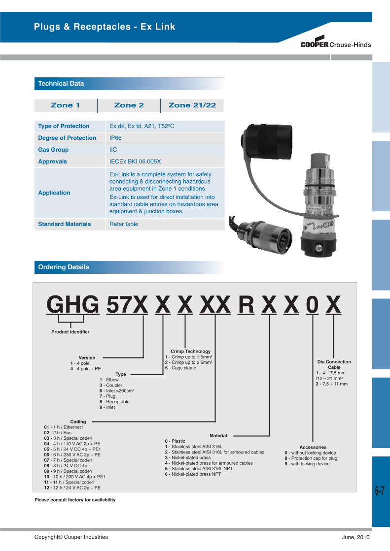
GHG 57X X X XX R X X 0 X
Type of Protection Ex de, Ex td, A21, T520C
Degree of Protection IP66
Gas Group IIC
Approvals IECEx BKI 06.005X
Application
Ex-Link is a complete system for safelyconnecting & disconnecting hazardousarea equipment in Zone 1 conditions.Ex-Link is used for direct installation intostandard cable entries on hazardous areaequipment & junction boxes.
Standard Materials Refer table
Technical Data
Zone 1 Zone 2 Zone 21/22
Plugs & Receptacles - Ex Link
Ordering Details
Type1 - Elbow3 - Coupler6 - Inlet >200cm3
7 - Plug8 - Receptable9 - Inlet
Version1 - 4 pole4 - 4 pole + PE
Please consult factory for availability
Product Identifier
Crimp Technology1 - Crimp up to 1.5mm2
2 - Crimp up to 2.5mm2
6 - Cage clamp
Coding01 - 1 h / Ethernet102 - 2 h / Bus03 - 3 h / Special code104 - 4 h / 110 V AC 2p + PE05 - 5 h / 24 V DC 4p + PE106 - 6 h / 230 V AC 2p + PE07 - 7 h / Special code108 - 8 h / 24 V DC 4p09 - 9 h / Special code110 - 10 h / 230 V AC 4p + PE111 - 11 h / Special code112 - 12 h / 24 V AC 2p + PE
Material0 - Plastic1 - Stainless steel AISI 316L2 - Stainless steel AISI 316L for armoured cables3 - Nickel-plated brass4 - Nickel-plated brass for armoured cables5 - Stainless steel AISI 316L NPT6 - Nickel-plated brass NPT
Accessories0 - without locking device8 - Protection cap for plug9 - with locking device
Dia ConnectionCable
1 - 4 – 7,5 mm/12 – 21 mm2
2 - 7,5 – 11 mm
6-7
Copyright© Cooper Industries June, 2010
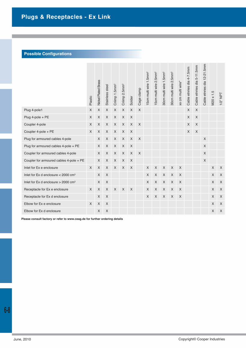
Plugs & Receptacles - Ex Link
6-8
Plug 4-pole1 X X X X X X X X X
Plug 4-pole + PE X X X X X X X X
Coupler 4-pole X X X X X X X X X
Coupler 4-pole + PE X X X X X X X X
Plug for armoured cables 4-pole X X X X X X X
Plug for armoured cables 4-pole + PE X X X X X X
Coupler for armoured cables 4-pole X X X X X X X
Coupler for armoured cables 4-pole + PE X X X X X X
Inlet for Ex e enclosure X X X X X X X X X X X X X
Inlet for Ex d enclosure < 2000 cm3 X X X X X X X X X
Inlet for Ex d enclosure > 2000 cm3 X X X X X X X X X
Receptacle for Ex e enclosure X X X X X X X X X X X X X
Receptacle for Ex d enclosure X X X X X X X X X
Elbow for Ex e enclosure X X X X X
Elbow for Ex d enclosure X X X X
Plastic
NickelPlatedBrass
Stainlesssteel
Criimp1.5mm2
Criimp2.5mm2
Solder
Cageclamp
15cm
multiwire1.5mm2
15cm
multiwire2.5mm2
30cm
multiwire1.5mm2
30cm
multiwire2.5mm2
xxcm
multiwire*
Cableetnriesdia4-7.5mm
Cableetnriesdia5-11.5mm
Cableetnriesdia12-21.5mm
M20x1.5
1/2”NPT
Possible Configurations
Please consult factory or refer to www.ceag.de for further ordering details
June, 2010 Copyright© Cooper Industries

CatalogueExplosion-Protected ProductsCooper Crouse-Hinds Australia
Valid from June 2010 ©2010 Cooper Industries, Plc.
Your Authorized Cooper Crouse-Hinds Distributor is:
Cooper Industries, Ltd.600 Travis, Ste. 5800Houston, TX 77002-1001P:713-209-8400www.cooperindustries.com
www.crouse-hinds.comCooper Crouse-Hinds is a registered trademarkof Cooper Industries, Plc.©2010 Cooper Industries, Plc.
Cooper Crouse-Hinds (Global HQ)Wolf & Seventh North StreetsSyracuse, NY 13221(866) 764-5454FAX: (315) [email protected]
Cooper Crouse-HindsMTL InstrumentsGreat Marlings, ButterfieldLuton UK LU2 8DL+44 (0)1582 723633FAX: +44 (0)1582 [email protected]
Cooper Crouse-Hinds Pauluhn1616 N Main StPearland, TX 77581(281) 485-4311FAX: (281) [email protected]
Cooper Crouse-HindsAirport Lighting1200 Kennedy RoadWindsor, CT 06095(860) 683-4354FAX: (860) [email protected]
Cooper Crouse-Hinds GmbHNeuer Weg-Nord 49Eberbach, Germany D-6941249 (0) 6271 806-500FAX: 49 (0) 6271 [email protected]
For more information:If further assistance is required, please contact an authorized Cooper Crouse-Hinds Distributor,Sales Office, or Customer Service Department.
Cooper Crouse-Hinds Regional Offices
Australia:61-2-8787-2777FAX: [email protected]
China:86-21-2899-3600FAX: [email protected]
Canada:800-265-0502FAX: (800) 263-9504FAX Orders only: (866) 653-0645
Mexico/Latin America/Caribbean:52-555-804-4000FAX: [email protected]
Saudi Arabia:966 3 812 2236FAX: 966 3 812 1291
India:91-124-4683888FAX: [email protected]
Brazil:+55 15 3238 3970FAX: +55 15 3238 [email protected]
Colombia:+ (57.1) 670 0315FAX: + (57.1) 670 [email protected]
Canada (Pauluhn):[email protected]
Middle East (Dubai):971 4 4272500FAX: 971 4 4298521
Korea:82 2 538 3425FAX: 82 2 538 [email protected]
Singapore:65-6297-4849FAX: [email protected]
UK:+44 247-630-89 30FAX: +44 247-630-10 [email protected]
Australia C
atalog
ue