cav controllers – type rn - trox uk
TRANSCRIPT

Actuator for switching between setpoint values
Tested to VDI 6022
01/2017
HY
GIENE TESTED
VDI 6022
– DE/en
CAV controllersType RN
Circular self-powered volume flow controllers for the control of supply air or extract air in constant air volume systems
■ Volume flow rate can be set using an external scale, no tools required ■ High control accuracy ■ No on-site test measurements required for commissioning ■ Suitable for airflow velocities of up to 12 m/s ■ Any installation orientation; maintenance-free ■ Casing air leakage to EN 1751, class C
Optional equipment and accessories ■ Acoustic cladding for the reduction of case-radiated noise ■ Secondary silencer Type CA, CS or CF for the reduction of air-regenerated
noise ■ Hot water heat exchanger Type WL and electric air heater Type EL for
reheating the airflow ■ Actuator for switching between setpoint values
X XRNtestregistrierung
PD – RN – 1
For the precise control of constant volume flow rates

CAV controllersGeneral information
01/2017 – DE/en
RN
Type
RN General information RN – 2Function RN – 4Technical data RN – 5Quick sizing RN – 6Specification text RN – 8Order code RN – 9Variants RN – 11Attachments RN – 13Dimensions and weight RN – 14Installation details RN – 19Basic information and nomenclature RN – 21
Application– Circular CONSTANTFLOW CAV controllers of
Type RN for the precise supply air or extract air flow control in constant air volume systems
– Mechanical self-powered volume flow control without external power supply
– Simplified project handling with orders based on nominal size
– Volume flow rate setpoint can be set on external scale
– Switchingbetweenmin andmax using optional actuator
Special features– Volume flow rate can be set using an external
scale; no tools required– High volume flow rate control accuracy– Any installation orientation
Nominal sizes– RN-S: 80, 100, 125– RN: 80, 100, 125, 160, 200, 250, 315, 400– RN-FL: 100, 125, 160, 200, 250, 315, 400
Variants– RN-S: Compact-height volume flow controller– RN: Volume flow controller– RN-D: Volume flow controller with acoustic
cladding– RN-FL: Volume flow controller with flanges on
both ends– RN-D-FL: Volume flow controller with acoustic
cladding and flanges on both ends– Units with acoustic cladding and/or a
secondary silencer Type CA, CS or CF for demanding acoustic requirements
– Acoustic cladding cannot be retrofitted
Construction– Galvanised sheet steel– P1: Powder-coated, silver grey (RAL 7001)– A2: Stainless steel
Parts and characteristics– Ready-to-commission controller– Damper blade with low-friction bearings– Bellows that acts as an oscillation damper– Cam plate with leaf spring– Scale with pointer to set the volume flow rate
setpoint– Aerodynamic function testing of each unit on a
special test rig prior to shipping– Correct operation even under unfavourable
upstream conditions (1.5 D straight section required upstream)
Attachments– Min/Max actuators: Actuators for switching
between minimum and maximum volume flow rate setpoint values
– Modulating actuators: Actuators for the stepless adjustment of volume flow rates or to switch between minimum and maximum volume flow rate setpoint values
– Retrofit kits: Actuators and installation accessories
– Variant RN-S cannot be combined with an actuator
Accessories– Lip seals on both ends (factory fitted)– Matching flanges for both ends
Useful additions– Secondary silencer Type CA, CS or CF– Heat exchanger Type WL– Electric air heater Type EL
Construction features– Circular casing– Spigot suitable for circular ducts to EN 1506 or
EN 13180– Spigot with groove for lip seal (RN-P1/80 and
RN-A2/80 without groove)– RN-FL: Circular flanges to EN 12220
Materials and surfacesGalvanised sheet steel construction– Casing made of galvanised sheet steel– Interior parts, nominal sizes 80 – 125: stainless
steel 1.4301, nominal sizes 160 – 400: galvanised sheet steel
Page
PD – RN – 2
Application
Description

CAV controllersGeneral information
01/2017 – DE/en
RN
– Polyurethane bellows– Plain bearings with PTFE coating– Leaf spring made of stainless steel
Powder-coated construction (P1)– Casing made of galvanised sheet steel,
powder-coated– Interior parts, nominal sizes 80 – 125: stainless
steel 1.4301, nominal sizes 160 – 400: galvanised sheet steel, powder-coated
Stainless steel construction (A2)– Casing made of stainless steel 1.4301– Interior parts made of stainless steel
Variant with acoustic cladding (-D)– Acoustic cladding made of galvanised sheet
steel– Rubber profile for the insulation of structure-
borne noise
– Lining is mineral wool
Mineral wool– To EN 13501, fire rating class A1, non-
combustible– RAL quality mark RAL-GZ 388– Biosoluble and hence hygienically safe
according to the German TRGS 905 (Technical Rules for Hazardous Substances) and EU directive 97/69/EC
Standards and guidelines– Hygiene conforms to VDI 6022– Casing air leakage to EN 1751, class C
Maintenance– Maintenance-free as construction and
materials are not subject to wear
PD – RN – 3

CAV controllersFunction
01/2017 – DE/en
RN
Functional descriptionThe volume flow controller is a mechanical self- powered unit and works without external power supply. A damper blade with low-friction bearings is adjusted by aerodynamic forces such that the set volume flow rate is maintained within the differential pressure range.The aerodynamic forces of the airflow create a closing torque on the damper blade. The bellows extends and increases this force while at the same time acting as an oscillation damper. The closing force is countered by a leaf spring that unrolls over a cam plate. The shape of the cam plate is such that a change in the differential pressure leads to an adjustment of the damper blade in a way that the volume flow rate is maintained almost exactly.
Efficient commissioningThe volume flow rate setpoint value can be set quickly and easily using the pointer on the external scale; no measurements are required.The advantage over flow adjustment dampers is that there is no need for repeat measurements or adjustments by an air conditioning engineer. Should the system pressure change, e.g. by opening or closing of duct sections, the flow rates in the entire system will also change if flow adjustment dampers are used; however, this is not the case with mechanical self-powered volume flow controllers A mechanical self-powered controller reacts immediately and adjusts the damper blade such that the set constant volume flow rate is maintained.
PD – RN – 4
Schematic illustration of the RN
② ③ ④
⑤
⑧⑨
⑦
①
⑥
①Damperblade②Bellows③Bellowsinlet④Crossbar⑤Leafspring
⑥Camplate⑦Volumeflowratescalelock⑧Volumeflowratescale⑨Lipseal

CAV controllersTechnical data
01/2017 – DE/en
RN
Volume flow rate rangesThe minimum differential pressure of CAV controllers is an important factor in designing the ductwork and in rating the fan including speed control.
Sufficient duct pressure must be ensured for all operating conditions and for all control units. The measurement points for fan speed control must be selected accordingly.
PD – RN – 5
RN, Volume flow rate ranges and minimum differential pressures
① ② ③ ④
Nominal size∆pst min ∆
l/s m³/h Pa Pa Pa Pa ± %
80
11 40 100 105 105 105 2020 72 100 105 105 105 1540 144 100 110 115 120 1045 162 100 110 120 125 8
100
22 79 50 55 55 55 1040 144 50 55 55 60 870 252 50 60 65 70 690 324 50 60 70 80 5
125
35 126 50 55 55 55 1060 216 50 55 55 55 8
115 414 50 60 65 70 6140 504 50 60 70 80 5
160
60 216 50 55 55 55 10105 378 50 55 55 55 8190 684 50 55 60 60 6240 864 50 55 65 70 5
200
90 324 50 55 55 55 10160 576 50 55 55 55 8300 1080 50 55 60 65 6360 1296 50 55 60 65 5
250
145 522 50 55 55 55 10255 918 50 55 55 55 8470 1692 50 55 60 60 6580 2088 50 55 60 65 5
315
230 828 50 55 55 55 10400 1440 50 55 55 55 8750 2700 50 55 60 60 6920 3312 50 55 60 65 5
400
350 1260 50 55 55 55 10610 2196 50 55 55 55 8
1130 4068 50 55 55 55 61400 5040 50 55 55 60 5
①RN②RNwithsecondarysilencerCS/CF,insulationthickness50mm,length500mm③RNwithsecondarysilencerCS/CF,insulationthickness50mm,length1000mm④RNwithsecondarysilencerCS/CF,insulationthickness50mm,length1500mm
Nominal sizes 80 – 400 mmVolume flow rate range 11 – 1400 l/s or 40 – 5040 m³/hVolume flow rate control range Approx. 25 to 100 % of the nominal volume flow rateScale accuracy ± 4 %Minimum differential pressure 50 Pa (nominal size 80: 100 Pa)Maximum differential pressure 1000 PaOperating temperature 10 – 50 °C

CAV controllersQuick sizing
01/2017 – DE/en
RN
Quick sizing tables provide a good overview of the room sound pressure levels that can be expected. Approximate intermediate values can be interpolated. Precise intermediate values and spectral data can be calculated with our Easy Product Finder design programme.The first selection criteria for the nominal size are theactualvolumeflowratesminandmax. The quick sizing tables are based on generally accepted attenuation levels. If the sound pressure level exceeds the required level, a larger air terminal unit and/or a silencer is required.
Sizing example
PD – RN – 6
RN, Sound pressure level at differential pressure 150 Pa
Nominal size
Air-regenerated noise Case-radiated noise① ② ③ ④ ① ⑤LPA LPA1 LPA2 LPA3
l/s m³/h dB(A)
80
11 40 37 24 17 15 22 <1520 72 39 27 19 17 24 <1540 144 47 34 24 22 31 <1545 162 48 35 25 24 32 <15
100
22 79 37 24 17 15 22 <1540 144 40 29 22 20 21 <1570 252 47 35 27 26 29 <1590 324 50 38 30 29 33 <15
125
35 126 37 27 21 18 15 <1560 216 43 34 27 25 19 <15
115 414 50 41 35 33 27 <15140 504 52 44 39 37 30 <15
160
60 216 40 32 26 24 29 <15105 378 45 37 32 29 33 <15190 684 49 41 35 33 39 <15240 864 50 41 36 34 41 16
200
90 324 40 31 24 22 28 <15160 576 43 35 28 26 32 <15300 1080 48 40 33 32 40 17360 1296 49 41 35 33 42 20
250
145 522 41 32 24 22 29 15255 918 42 34 28 26 33 <15470 1692 46 39 33 31 40 19580 2088 48 41 35 34 43 22
315
230 828 39 33 26 23 30 <15400 1440 42 35 29 27 35 <15750 2700 44 38 32 31 40 19920 3312 46 41 35 34 43 23
400
350 1260 46 39 33 29 45 <15610 2196 48 42 36 32 49 18
1130 4068 50 44 38 35 54 241400 5040 51 45 40 37 56 27
①RN②RNwithsecondarysilencerCS/CF,insulationthickness50mm,length500mm③RNwithsecondarysilencerCS/CF,insulationthickness50mm,length1000mm④RNwithsecondarysilencerCS/CF,insulationthickness50mm,length1500mm⑤RN-D

CAV controllersQuick sizing
01/2017 – DE/en
RN
Given datamax = 280 l/s (1010 m3/h)Δpst = 150 PaRequired sound pressure level in the room 35 dB(A)
Quick sizingRN/200 with circular silencer CS 050/200×1000Air-regenerated noise LPA = 26 dB(A)Case-radiated noise LPA = 31 dB(A)
PD – RN – 7

CAV controllersSpecification text
01/2017 – DE/en
RN
This specification text describes the general properties of the product. Texts for variants can be generated with our Easy Product Finder design programme.
Circular volume flow controllers for constant air volume systems, mechanical self-powered, without external power supply, suitable for supply or extract air, available in 8 nominal sizes.Ready-to-commission unit consists of the casing containing a damper blade with low-friction bearings, bellows, external cam plate and leaf spring.Volume flow controllers without actuators are factory set to a reference volume flow rate (customers can set the required volume flow rate on site).Spigot with groove for lip seal, suitable for connecting ducts according to EN 1506 or EN 13180.Casing air leakage to EN 1751, class C.
Special features– Volume flow rate can be set using an external
scale; no tools required– High volume flow rate control accuracy– Any installation orientation
Materials and surfacesGalvanised sheet steel construction– Casing made of galvanised sheet steel– Interior parts, nominal sizes 80 – 125: stainless
steel 1.4301, nominal sizes 160 – 400: galvanised sheet steel
– Polyurethane bellows– Plain bearings with PTFE coating– Leaf spring made of stainless steel
Powder-coated construction (P1)– Casing made of galvanised sheet steel,
powder-coated– Interior parts, nominal sizes 80 – 125: stainless
steel 1.4301, nominal sizes 160 – 400: galvanised sheet steel, powder-coated
Stainless steel construction (A2)– Casing made of stainless steel 1.4301– Interior parts made of stainless steel
Variant with acoustic cladding (-D)– Acoustic cladding made of galvanised sheet
steel– Rubber profile for the insulation of structure-
borne noise– Lining is mineral wool
Mineral wool– To EN 13501, fire rating class A1, non-
combustible– RAL quality mark RAL-GZ 388– Biosoluble and hence hygienically safe
according to the German TRGS 905 (Technical Rules for Hazardous Substances) and EU directive 97/69/EC
Construction– Galvanised sheet steel– P1: Powder-coated, silver grey (RAL 7001)– A2: Stainless steel
Technical data– Nominal sizes: 80 to 400 mm– Volume flow rate range: 11 to 1400 l/s or
40 to 5040 m³/h– Volume flow rate control range:
approx. 25 – 100 % of the nominal volume flow rate
– Minimum differential pressure: 50 Pa (nominal size 80: 100 Pa)
– Maximum differential pressure: 1000 Pa
Sizing data– ____________ _______________________
[m³/h]– Δpst __________ _______________________
[Pa]Air-regenerated noise– LPA ___________ _______________________
[dB(A)]Case-radiated noise– LPA ___________ _______________________
[dB(A)]
PD – RN – 8

CAV controllersOrder code
01/2017 – DE/en
RN
Notes on the order codeRN-S– RN-S-A2/80: no lip seal (D2)
RN– RN/80: no flange (FL), no matching flange (G2)– RN-A2/80: no lip seal (D2)
PD – RN – 9
RN-S
RN-S – P1 / 100 / D2
TypeRN-S Volume flow controller
Material No entry: galvanised sheet steelP1 Powder-coated (RAL 7001), silver greyA2 Stainless steel
Nominalsize[mm]80100125
Accessories No entry: noneD2 Lip seals on both ends
RN
RN – D – P1 – FL / 160 / G2 / B50 / 300 – 800
TypeRN Volume flow controller
Acousticcladding No entry: noneD With acoustic cladding
Material No entry: galvanised sheet steelP1 Powder-coated (RAL 7001), silver greyA2 Stainless steel
Flange No entry: noneFL Flanges on both ends
Nominalsize[mm]80100125160200250315400
Accessories No entry: noneD2 Lip seals on both endsG2 Matching flanges for both ends
Actuator No entry: without For exampleB50 24 V AC/DC, 3-pointB52 24 V AC/DC, 3-point, with auxiliary switchB70 24 V AC/DC, modulating 2 – 10 V DC
Volumeflowrates[m3/h or l/s] onlyactuators min – max for factory setting
Order example: RN/160/D2Nominal size 160Material Galvanised sheet steelAccessories Lip seal on both ends

CAV controllersOrder code
01/2017 – DE/en
RN
PD – RN – 10
Order example: RN-D-FL/250/G2/B50Acoustic cladding WithFlange Both endsMaterial Galvanised sheet steelNominal size 250Accessories Matching flanges for both endsActuator B50

CAV controllersVariants
01/2017 – DE/en
RN
RN-S– Compact-height volume flow controller for
constant volume flow rate control– Spigot to make connections to the ducting
RN– Volume flow controller for constant air volume
flow control– Spigot to make connections to the ducting
RN-D– Volume flow controller with acoustic cladding
for constant air volume flow control– Spigot to make connections to the ducting– For rooms where the case-radiated noise of the
unit is not sufficiently reduced by a false ceiling
– The circular ducts for the room under consideration must have adequate acoustic insulation (provided by others) on the fan and room ends
– Acoustic cladding cannot be retrofitted
RN-FL– Volume flow controller for constant air volume
flow control
– With flanges to make detachable connections to the ductwork
RN-D-FL– Volume flow controller with acoustic cladding
for constant air volume flow control– With flanges to make detachable connections
to the ductwork– For rooms where the case-radiated noise of the
unit is not sufficiently reduced by a false ceiling– The circular ducts for the room under
PD – RN – 11
CAV controller variant RN-S, compact height CAV controller variant RN
CAV controller variant RN-D CAV controller variant RN, with actuator for switching between setpoint values

CAV controllersVariants
01/2017 – DE/en
RN
consideration must have adequate acoustic insulation (provided by others) on the fan and room ends
– Acoustic cladding cannot be retrofitted– Powder-coated surface (P1) or stainless steel
construction (A2) not possible
PD – RN – 12
MaterialsOrder
code detail Part Material Notes
–
Casing Galvanised sheet steel
Damper blade Stainless steel, material no. 1.4301 Nominal size 80
Damper blade Stainless steel, material no. 1.4310 Nominal sizes: 100, 125
Damper blade Galvanised sheet steel Nominal sizes from 160
Shaft Stainless steel, material no. 1.4301 Nominal sizes 80 to 200
Shaft Stainless steel, material no. 1.4104 Nominal sizes 250 to 400
Plain bearings Steel with PTFE coating
D
Acoustic cladding Galvanised sheet steelRubber profile for the insulation of structure-
borne noise Rubber
Lining Mineral wool
P1
Casing Galvanised sheet steel Powder-coated
Damper blade Stainless steel, material no. 1.4301 Nominal size 80
Damper blade Stainless steel, material no. 1.4310 Nominal sizes: 100, 125
Damper blade Galvanised sheet steel Powder-coated, nominal sizes from 160
Shaft Stainless steel, material no. 1.4301 Nominal sizes 80 to 200
Shaft Stainless steel, material no. 1.4305 Nominal sizes 250 to 400
Plain bearings Bronze with PTFE coating
A2
Casing Stainless steel, material no. 1.4301
Damper blade Stainless steel, material no. 1.4301 Nominal size 80
Damper blade Stainless steel, material no. 1.4310 Nominal sizes: 100, 125
Damper blade Stainless steel, material no. 1.4301 Nominal sizes from 160
Shaft Stainless steel, material no. 1.4301 Nominal sizes 80 to 200
Shaft Stainless steel, material no. 1.4305 Nominal sizes 250 to 400
Plain bearings Bronze with PTFE coating
SurfacesOrder code detail Part Surface Notes
– Casing UntreatedP1 Casing Powder-coated, RAL 7001, silver grey

CAV controllersAttachments
01/2017 – DE/en
RN
PD – RN – 13
RN, actuatorsOrder code detail Actuator Supply voltage Auxiliary switch
Min/Max actuators
B50Actuator with mechanical
stops TROX/Belimo
24 V AC/DC –
B52Actuator with mechanical
stops TROX/Belimo
24 V AC/DC 2
B60Actuator with mechanical
stops TROX/Belimo
230 V AC –
B62Actuator with mechanical
stops TROX/Belimo
230 V AC 2
Modulating actuators
B70Actuator with mechanical
stops TROX/Belimo
24 V AC/DC –
B72Actuator with mechanical
stops TROX/Belimo
24 V AC/DC 2

CAV controllersDimensions and weight
01/2017 – DE/en
RN
PD – RN – 14
RN-S
Nominal sizeØD mmm kg
80 79 1.4
RN-S
Nominal sizeØD L A mmm mm mm kg
100 99 250 50 1.8125 124 250 50 2.0
RN-S/80, RN-S-P1/80, RN-S-A2/80 RN-S/80/D2, RN-S-P1/80/D2
RN-S, nominal size 80
RNS 80
250
ØD
130
30
RN-S, nominal size 80, lip seal
RNS 80
330
ØD
130
40
RN-S, nominal size 100, 125
ØD
130
L
40A

CAV controllersDimensions and weight
01/2017 – DE/en
RN
PD – RN – 15
RN
Nominal sizeØD L A mmm mm mm kg
80 79 310 50 1.4100 99 310 50 1.8125 124 310 50 2.0160 159 310 50 2.5200 199 310 50 3.0250 249 400 50 3.5315 314 400 50 4.8400 399 400 50 5.7
①RN②RNwithsecondarysilencerCS/CF,insulationthickness50mm,length500mm③RNwithsecondarysilencerCS/CF,insulationthickness50mm,length1000mm④RNwithsecondarysilencerCS/CF,insulationthickness50mm,length1500mm
RN-P1/80
RN 80
250
79
182
30
RN-P1/80/D2
RN 80
330
79
182
40
RN
L
ØD
182 ∼ 70 ∼ 80
A
174
∼ 90

CAV controllersDimensions and weight
01/2017 – DE/en
RN
PD – RN – 16
RN-D
Nominal sizeØD L ØD3 L1 mmm mm mm mm kg
80 79 310 181 232 2.2100 99 310 200 232 3.6125 124 310 220 232 4.0160 159 310 262 232 5.0200 199 310 300 232 6.0250 249 400 356 312 7.3315 314 400 418 312 9.8400 399 400 500 312 11.8
RN-A2/80
RN 80
310
79
182
50
RN-D
L₁
L
ØD
₃
ØD
∼ 70 ∼ 80182
174
∼ 90

CAV controllersDimensions and weight
01/2017 – DE/en
RN
PD – RN – 17
RN-FL
Nominal sizeØD L ØD1 ØD2 n T mmm mm mm mm mm kg
100 99 290 132 152 4 4 2.4125 124 290 157 177 4 4 2.7160 159 290 192 212 6 4 3.5200 199 290 233 253 6 4 4.4250 249 380 283 303 6 4 5.3315 314 380 352 378 8 4 7.3400 399 380 438 464 8 4 9.6
RN-D-P1/80/D2
RN 80
330
79181
182
232
RN-D-A2/80
RN 80
310
182
232
79181
RN-FL
L
ØD
∼ 70 ∼ 80182
ØD₁
ØD₂
n × Ø9,5
T
174
∼ 90
ØD₁
ØD₂
n × Ø9.5
T
174
∼ 90
L
ØD
∼ 70 ∼ 80182

CAV controllersDimensions and weight
01/2017 – DE/en
RN
PD – RN – 18
RN-D-FL
Nominal sizeØD L ØD1 ØD2 ØD3 L1 n T mmm mm mm mm mm mm mm kg
100 99 370 132 152 200 232 4 4 4.2125 124 370 157 177 220 232 4 4 4.7160 159 370 192 212 262 232 6 4 6.0200 199 370 233 253 300 232 6 4 7.4250 249 460 283 303 356 312 6 4 9.1315 314 460 352 378 418 312 8 4 12.3400 399 460 438 464 500 312 8 4 15.7
RN-D-FL
L₁
L
ØD
₃
ØD
∼ 70 ∼ 80182
n × Ø9,5
T
174
ØD₁
ØD₂
∼ 90
L₁
L
ØD
₃
ØD
∼ 70 ∼ 80182

CAV controllersInstallation details
01/2017 – DE/en
RN
Installation and commissioning– Any installation orientation– Volume flow rate can be set using an external
scale; no tools required– No repeat measurements or adjustments by an
air conditioning engineer are necessary– RN-D: For constructions with acoustic
cladding, ducts on the room side should have cladding up to the acoustic cladding of the controller
Upstream conditionsThevolumeflowrateaccuracyΔappliestoastraight upstream section of the duct. Bends, junctions or a narrowing or widening of the duct cause turbulence that may affect measurement. Duct connections, e.g. branches off the main duct, must comply with EN 1505. Some installation situations require straight duct sections upstream.Free air intake only with a straight duct section of 1D upstream.
Space required for commissioning and maintenanceSufficient space must be kept clear near any attachments to allow for commissioning and maintenance. It may be necessary to provide sufficiently sized inspection access openings.
PD – RN – 19
A bend with a curvature radius of at least 1D – without an additional straight duct section upstream of the CAV controller – has only a negligible effect on the volume flow rate accuracy.
Bend
D
1D
CAV controllersInstallation details
01/2017 – DE/en
RN
PD – RN – 20
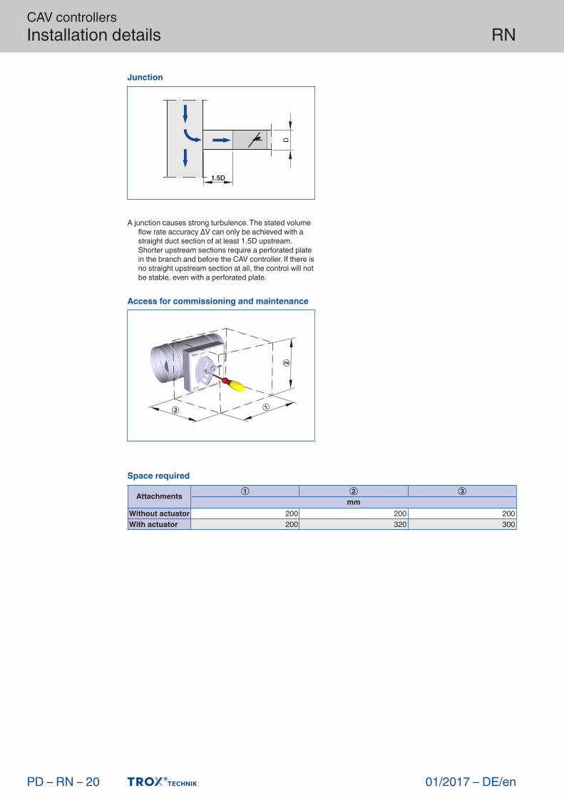
Space required
Attachments① ② ③
mmWithout actuator 200 200 200With actuator 200 320 300
A junction causes strong turbulence. The stated volume flowrateaccuracyΔcanonlybeachievedwithastraight duct section of at least 1.5D upstream. Shorter upstream sections require a perforated plate in the branch and before the CAV controller. If there is no straight upstream section at all, the control will not be stable, even with a perforated plate.
Junction
1.5D1.5D
D
Access for commissioning and maintenance
①③
②

CAV controllersBasic information and nomenclature
01/2017 – DE/en
RN
Prinipal dimensions
ØD [mm]Outside diameter of the spigot
ØD₁ [mm]Pitch circle diameter of flanges
ØD₂ [mm]Outside diameter of flanges
ØD₄ [mm]Inside diameter of the screw holes of flanges
L [mm]Length of unit including connecting spigot
L₁ [mm]Length of casing or acoustic cladding
B [mm]Duct width
B₁ [mm]Screw hole pitch of flange (horizontal)
B₂ [mm]
Outside dimension of flange (width)
B₃ [mm]Width of device
H [mm]Duct height
H₁ [mm]Screw hole pitch of flange (vertical)
H₂ [mm]Outside dimension of flange (height)
H₃ [mm]Unit height
n [ ]Number of flange screw holes
T [mm]Flange thickness
m [kg]Unit weight including the minimum required attachments for manual adjustment
Acoustic data
fm [Hz]Octave band centre frequency
LPA [dB(A)]A-weighted sound pressure level of air- regenerated noise of the VAV terminal unit, system attenuation taken into account
LPA1 [dB(A)]A-weighted sound pressure level of air- regenerated noise of the VAV terminal unit with secondary silencer, system attenuation taken into account
LPA2 [dB(A)]A-weighted sound pressure level of case- regenerated noise of the VAV terminal unit, system attenuation taken into account
LPA3 [dB(A)]A-weighted sound pressure level of case- regenerated noise of the VAV terminal unit with acoustic cladding, system attenuation taken into account
Allsoundpressurelevelsarebasedon20μPa.
Volume flow rates
nom [m³/h] and [l/s]Nominal volume flow rate (100 %)– The value depends on product type and
nominal size– Values are published on the internet and in
technical leaflets, and stored in the Easy Product Finder design software.
– Upper limit of the setting range and maximum
PD – RN – 21
Definition of noise
LPA
①②
①Air-regeneratednoise②Case-radiatednoise

CAV controllersBasic information and nomenclature
01/2017 – DE/en
RN
volume flow rate setpoint value for the CAV controller
[m³/h] and [l/s]
Volume flow rate
Δ [± %]Volume flow rate tolerance from setpoint value
Differential pressure
Δpst [Pa]Static differential pressure
Δpst min [Pa]Static differential pressure, minimum– The static minimum differential pressure is
equal to the pressure loss of the CAV controller when the damper blade is open, caused by flow resistance (bellows, crossbar)
– If the pressure on the CAV controller is too low,
the setpoint volume flow rate may not be achieved, not even when the damper blade is open
– Important factor in designing the ductwork and in rating the fan including speed control
– Sufficient duct pressure must be ensured for all operating conditions and for all controllers, and the measurement point or points for speed control must have been selected accordingly to achieve this
Construction
Galvanised sheet steel– Casing made of galvanised sheet steel– Parts in contact with the airflow as described
for the product type– External parts, e.g. mounting brackets or
covers, are usually made of galvanised sheet steel
Powder-coated surface (P1)– Casing made of galvanised sheet steel,
powder-coated RAL 7001, silver grey– Parts in contact with the airflow are powder-
coated or made of plastic
– Due to production, some parts that come into contact with the airflow may be stainless steel or aluminium, powder-coated
– External parts, e.g. mounting brackets or covers, are usually made of galvanised sheet steel
Stainless steel (A2)– Casing made of stainless steel 1.4201– Parts in contact with the airflow are powder-
coated or made of stainless steel– External parts, e.g. mounting brackets or
covers, are usually made of galvanised sheet steel
PD – RN – 22
Static differential pressure
∆pst