chapter 11 op-amp applications - web page for staffwebstaff.kmutt.ac.th/~suwat.pat/material/ene212...
TRANSCRIPT
Chapter 11Op-Amp Applications
OpOp--Amp ApplicationsAmp Applications
ConstantConstant--gain multipliergain multiplierVoltage summingVoltage summing
Voltage bufferVoltage bufferControlled sourcesControlled sources
Instrumentation circuitsInstrumentation circuitsActive filtersActive filters
Copyright ©2009 by Pearson Education, Inc.Upper Saddle River, New Jersey 07458 • All rights reserved.
Electronic Devices and Circuit Theory, 10/eRobert L. Boylestad and Louis Nashelsky
Active filtersActive filters
22

ConstantConstant--Gain AmplifierGain Amplifier
Inverting VersionInverting Version
Copyright ©2009 by Pearson Education, Inc.Upper Saddle River, New Jersey 07458 • All rights reserved.
Electronic Devices and Circuit Theory, 10/eRobert L. Boylestad and Louis Nashelsky
more…more…
33
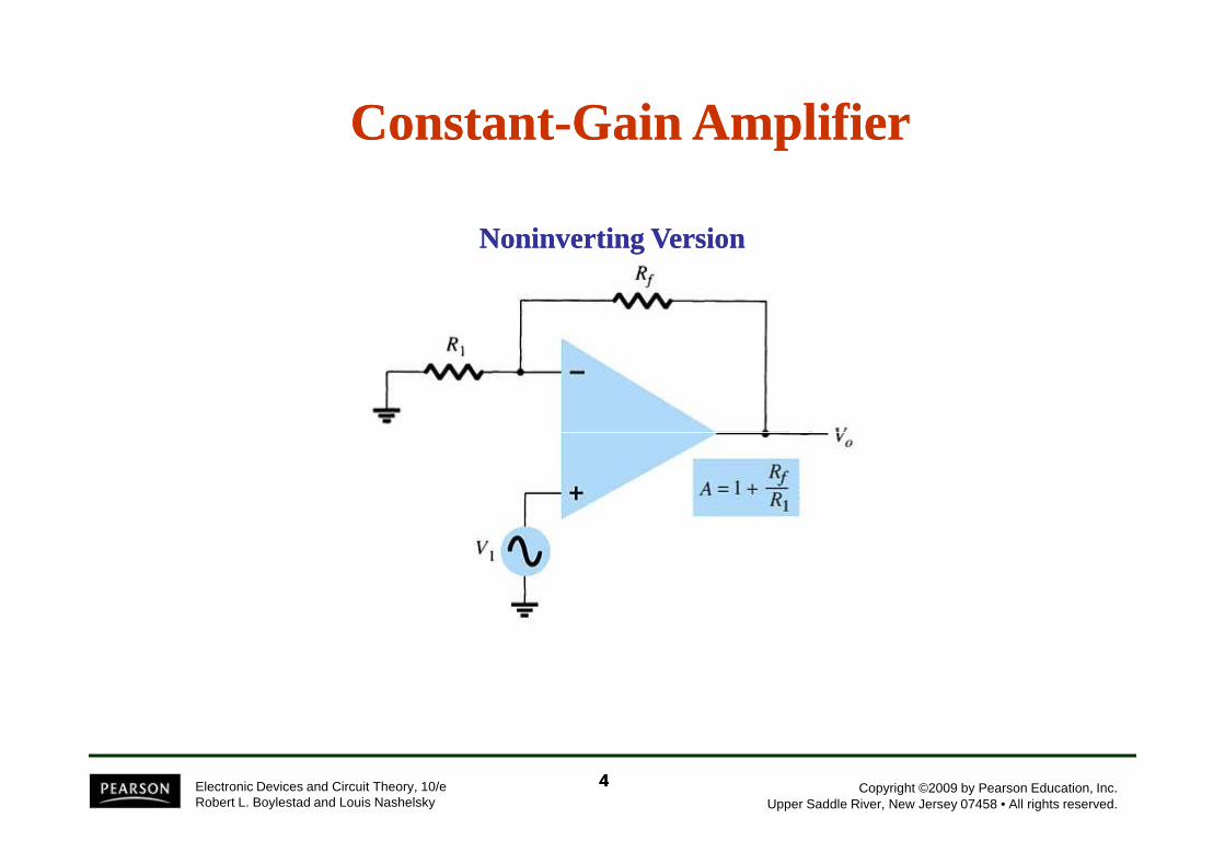
ConstantConstant--Gain AmplifierGain Amplifier
Noninverting VersionNoninverting Version
Copyright ©2009 by Pearson Education, Inc.Upper Saddle River, New Jersey 07458 • All rights reserved.
Electronic Devices and Circuit Theory, 10/eRobert L. Boylestad and Louis Nashelsky
44

MultipleMultiple--Stage GainsStage Gains
= AAAA 321
The total gain (3-stages) is given by:
or
Copyright ©2009 by Pearson Education, Inc.Upper Saddle River, New Jersey 07458 • All rights reserved.
Electronic Devices and Circuit Theory, 10/eRobert L. Boylestad and Louis Nashelsky
55
−
−
+=
R3R
R2R
RR
1A ff
1
f
or
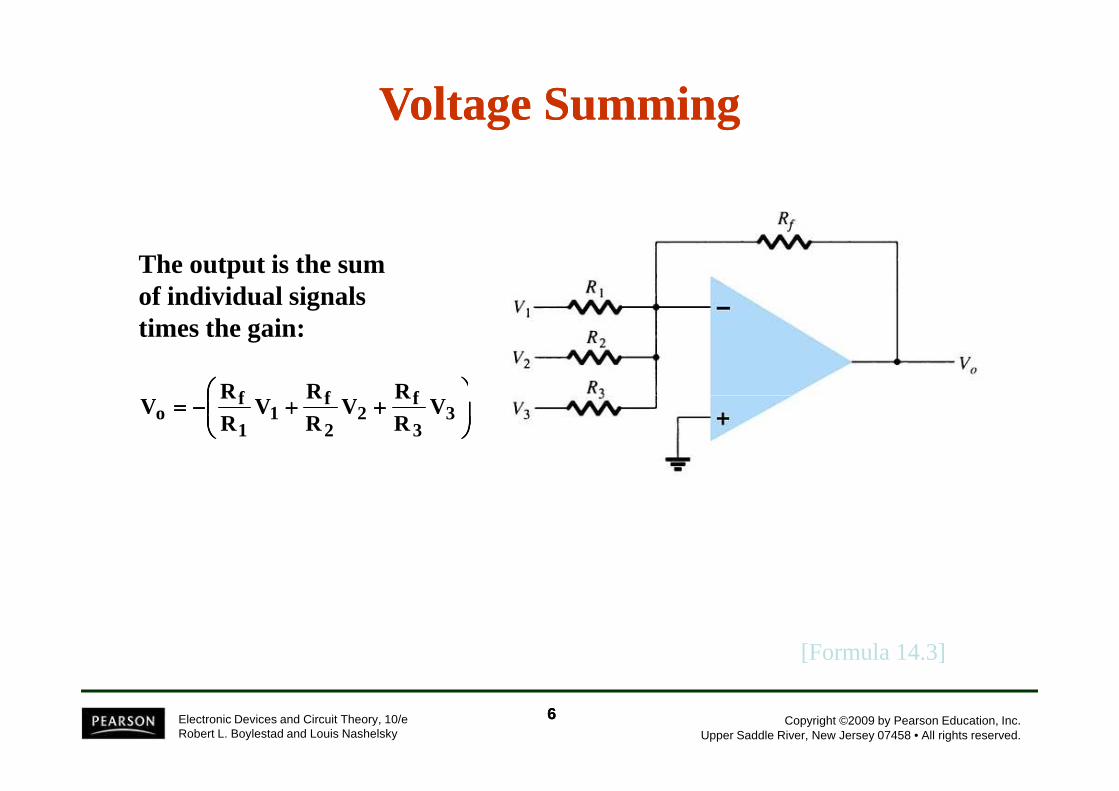
Voltage SummingVoltage Summing
++++++++−−−−==== fff VR
VR
VR
V
The output is the sum of individual signals times the gain:
Copyright ©2009 by Pearson Education, Inc.Upper Saddle River, New Jersey 07458 • All rights reserved.
Electronic Devices and Circuit Theory, 10/eRobert L. Boylestad and Louis Nashelsky
[Formula 14.3]
++++++++−−−−==== 3
3
f2
2
f1
1
fo V
RR
VRR
VRR
V
66

Voltage BufferVoltage Buffer
Any amplifier with no gain or loss is called a unity gain unity gain amplifieramplifier. The advantages of using a unity gain amplifier:
• Very high input impedance • Very low output impedance
Copyright ©2009 by Pearson Education, Inc.Upper Saddle River, New Jersey 07458 • All rights reserved.
Electronic Devices and Circuit Theory, 10/eRobert L. Boylestad and Louis Nashelsky
Realistically these circuits are designed using equal resistors (R1 = Rf) to avoid problems with offset voltages.
77

Controlled SourcesControlled Sources
VoltageVoltage--controlled voltage sourcecontrolled voltage sourceVoltageVoltage--controlled current sourcecontrolled current sourceCurrentCurrent--controlled voltage sourcecontrolled voltage sourceCurrentCurrent--controlled current sourcecontrolled current source
Copyright ©2009 by Pearson Education, Inc.Upper Saddle River, New Jersey 07458 • All rights reserved.
Electronic Devices and Circuit Theory, 10/eRobert L. Boylestad and Louis Nashelsky
88
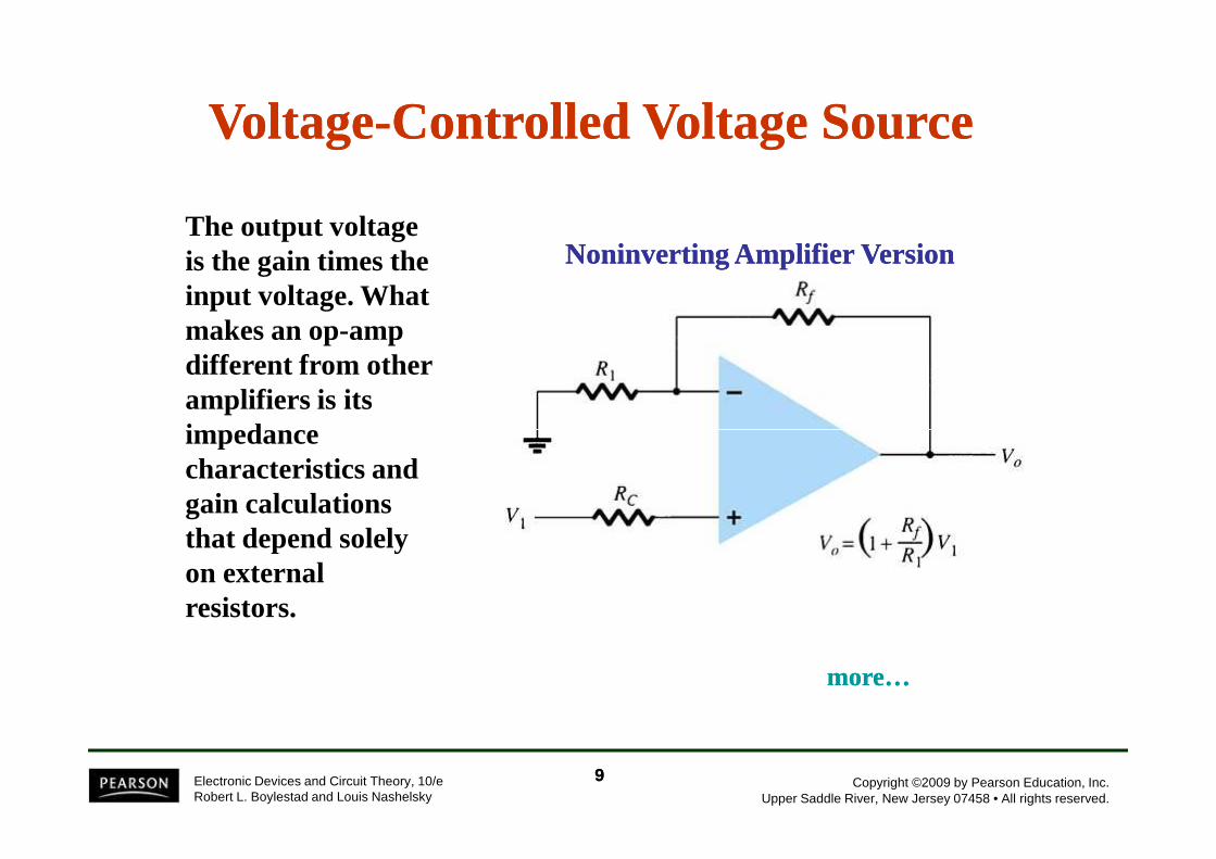
VoltageVoltage--Controlled Voltage SourceControlled Voltage Source
The output voltage is the gain times the input voltage. What makes an op-amp different from other amplifiers is its impedance
Noninverting Amplifier VersionNoninverting Amplifier Version
Copyright ©2009 by Pearson Education, Inc.Upper Saddle River, New Jersey 07458 • All rights reserved.
Electronic Devices and Circuit Theory, 10/eRobert L. Boylestad and Louis Nashelsky
impedance characteristics and gain calculations that depend solely on external resistors.
more…more…
99

VoltageVoltage--Controlled Voltage SourceControlled Voltage Source
The output voltage is the gain times the input voltage. What makes an op-amp different from other amplifiers is its impedance
Inverting Amplifier VersionInverting Amplifier Version
Copyright ©2009 by Pearson Education, Inc.Upper Saddle River, New Jersey 07458 • All rights reserved.
Electronic Devices and Circuit Theory, 10/eRobert L. Boylestad and Louis Nashelsky
impedance characteristics and gain calculations that depend solely on external resistors.
1010
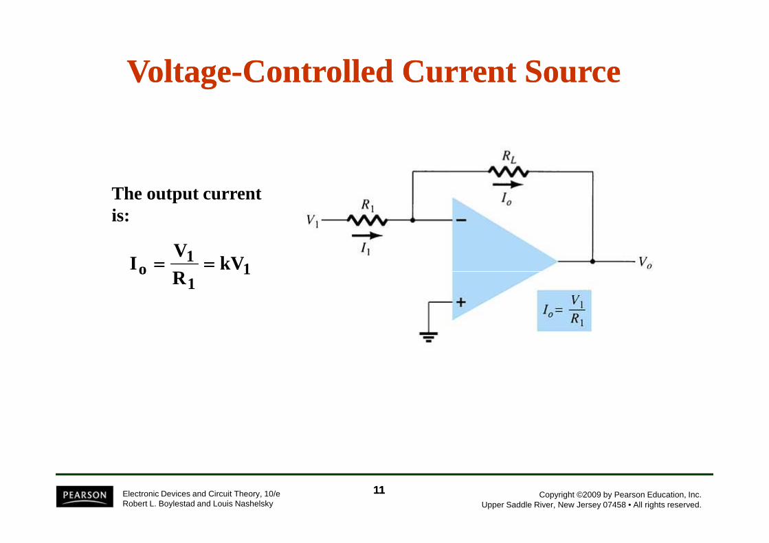
VoltageVoltage--Controlled Current SourceControlled Current Source
The output current is:
11
o kVRV
I ========
Copyright ©2009 by Pearson Education, Inc.Upper Saddle River, New Jersey 07458 • All rights reserved.
Electronic Devices and Circuit Theory, 10/eRobert L. Boylestad and Louis Nashelsky
11
o kVR
I ========
1111
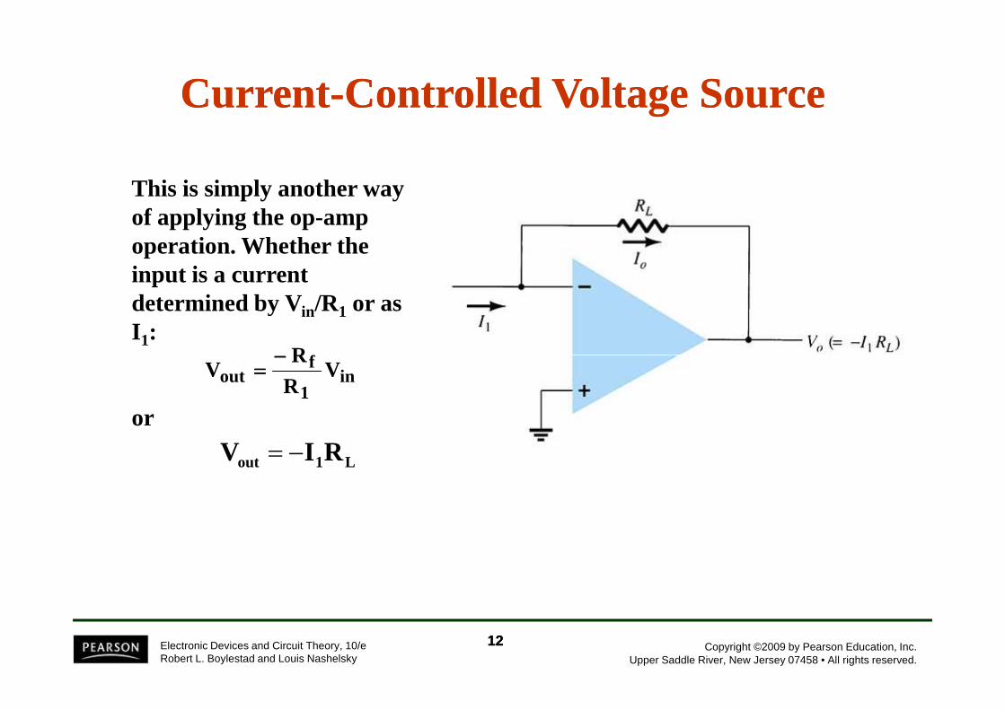
CurrentCurrent--Controlled Voltage SourceControlled Voltage Source
This is simply another way of applying the op-amp operation. Whether the input is a current determined by Vin/R1 or as I 1:
fR−−−−==
Copyright ©2009 by Pearson Education, Inc.Upper Saddle River, New Jersey 07458 • All rights reserved.
Electronic Devices and Circuit Theory, 10/eRobert L. Boylestad and Louis Nashelsky
or
in1
fout V
RR
V−−−−
====
1212
L1out RIV −=
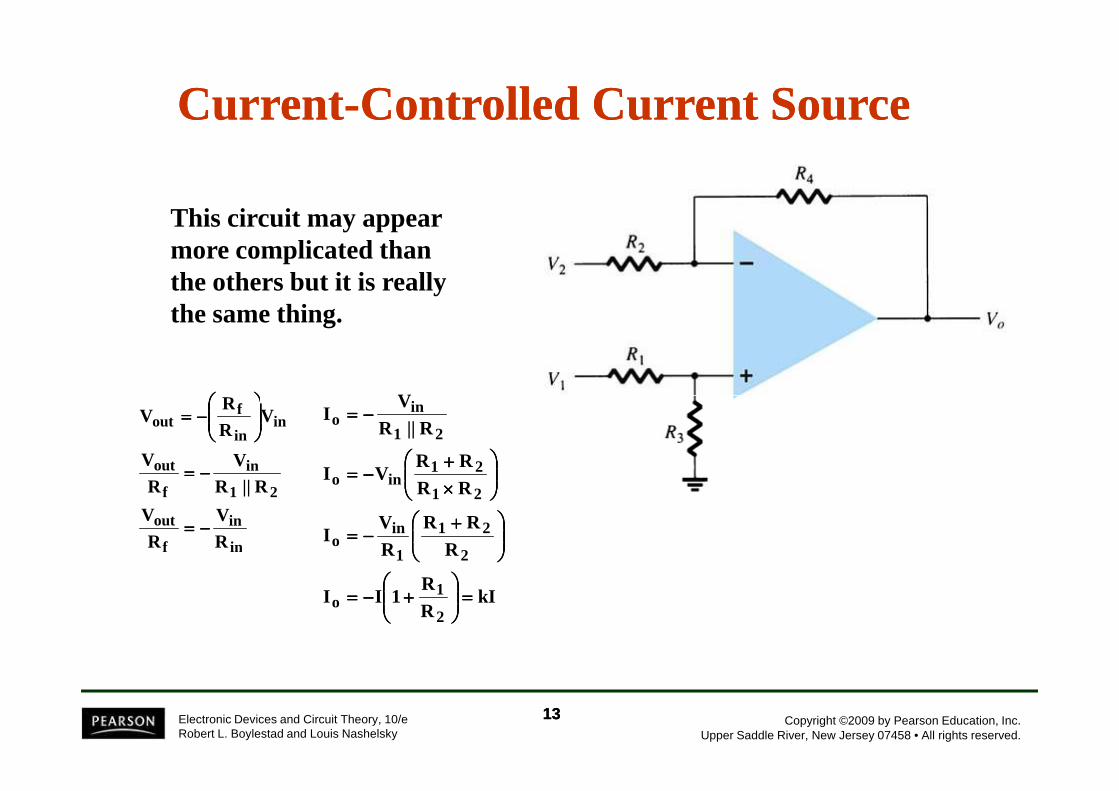
CurrentCurrent--Controlled Current SourceControlled Current Source
This circuit may appear more complicated than the others but it is really the same thing.
R V
Copyright ©2009 by Pearson Education, Inc.Upper Saddle River, New Jersey 07458 • All rights reserved.
Electronic Devices and Circuit Theory, 10/eRobert L. Boylestad and Louis Nashelsky
in
in
f
out
21
in
f
out
inin
fout
R
V
R
V
R||RV
R
V
VR
RV
−−−−====
−−−−====
−−−−====
kIRR
1II
RRR
RV
I
RRRR
VI
R||RV
I
2
1o
2
21
1
ino
21
21ino
21
ino
====
++++−−−−====
++++−−−−====
××××
++++−−−−====
−−−−====
1313

Instrumentation CircuitsInstrumentation Circuits
Some examples of instrumentation circuits using op-amps:
• Display driver• Instrumentation amplifier
Copyright ©2009 by Pearson Education, Inc.Upper Saddle River, New Jersey 07458 • All rights reserved.
Electronic Devices and Circuit Theory, 10/eRobert L. Boylestad and Louis Nashelsky
• Instrumentation amplifier
1414
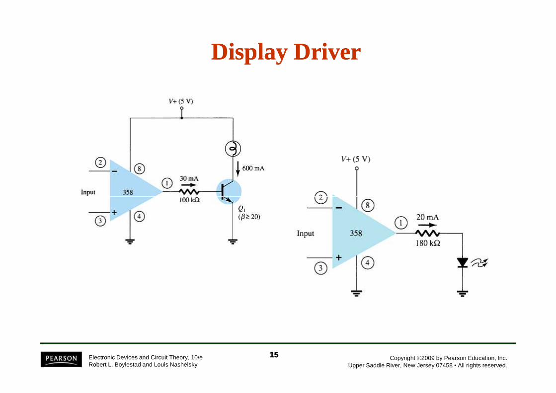
Display DriverDisplay Driver
Copyright ©2009 by Pearson Education, Inc.Upper Saddle River, New Jersey 07458 • All rights reserved.
Electronic Devices and Circuit Theory, 10/eRobert L. Boylestad and Louis Nashelsky
1515
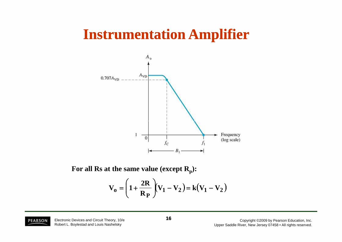
Instrumentation AmplifierInstrumentation Amplifier
Copyright ©2009 by Pearson Education, Inc.Upper Saddle River, New Jersey 07458 • All rights reserved.
Electronic Devices and Circuit Theory, 10/eRobert L. Boylestad and Louis Nashelsky
For all Rs at the same value (except Rp):
(((( )))) (((( ))))2121P
o VVkVVR2R
1V −−−−====−−−−
++++====
1616
Active FiltersActive Filters
Adding capacitors to op-amp circuits provides external control of the cutoff frequencies. The op-amp active filter provides controllable cutoff frequencies and controllable gain.
• Low-pass filter• High-pass filter• Bandpass filter
Copyright ©2009 by Pearson Education, Inc.Upper Saddle River, New Jersey 07458 • All rights reserved.
Electronic Devices and Circuit Theory, 10/eRobert L. Boylestad and Louis Nashelsky
1717

LowLow--Pass FilterPass Filter——FirstFirst--OrderOrder
Copyright ©2009 by Pearson Education, Inc.Upper Saddle River, New Jersey 07458 • All rights reserved.
Electronic Devices and Circuit Theory, 10/eRobert L. Boylestad and Louis Nashelsky
11OH CRπ2
1f ====
1
fv R
R1A ++++====
The upper cutoff frequency and voltage gain are given by:
1818
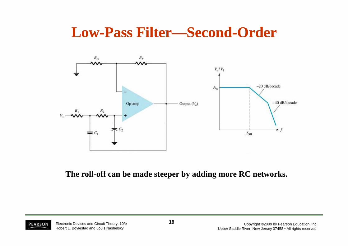
LowLow--Pass FilterPass Filter——SecondSecond--OrderOrder
Copyright ©2009 by Pearson Education, Inc.Upper Saddle River, New Jersey 07458 • All rights reserved.
Electronic Devices and Circuit Theory, 10/eRobert L. Boylestad and Louis Nashelsky
The roll-off can be made steeper by adding more RC networks.
1919

HighHigh--Pass FilterPass Filter
Copyright ©2009 by Pearson Education, Inc.Upper Saddle River, New Jersey 07458 • All rights reserved.
Electronic Devices and Circuit Theory, 10/eRobert L. Boylestad and Louis Nashelsky
11OL CRπ2
1f ====
The cutoff frequency is determined by:
2020

Bandpass Bandpass FilterFilter
There are two cutoff frequencies: upper and lower. They can be calculated using the same low-pass cutoff and high-pass cutoff frequency formulas in the
Copyright ©2009 by Pearson Education, Inc.Upper Saddle River, New Jersey 07458 • All rights reserved.
Electronic Devices and Circuit Theory, 10/eRobert L. Boylestad and Louis Nashelsky
formulas in the appropriate sections.
2121