chapter 15 power supplies (voltage regulators)webstaff.kmutt.ac.th/~suwat.pat/material/ene212 ch...
TRANSCRIPT

Chapter 15Power Supplies(Voltage Regulators)

Power Supply DiagramPower Supply DiagramPower Supply DiagramPower Supply DiagramPower Supply DiagramPower Supply DiagramPower Supply DiagramPower Supply Diagram
Copyright ©2009 by Pearson Education, Inc.Upper Saddle River, New Jersey 07458 • All rights reserved.
Electronic Devices and Circuit Theory, 10/eRobert L. Boylestad and Louis Nashelsky
22

Filter CircuitsFilter CircuitsFilter CircuitsFilter CircuitsFilter CircuitsFilter CircuitsFilter CircuitsFilter Circuits
• The output from the rectifier section is a pulsating DC.
• The filter circuit reduces the peak-to-peak pulses to a small ripple voltage.
Copyright ©2009 by Pearson Education, Inc.Upper Saddle River, New Jersey 07458 • All rights reserved.
Electronic Devices and Circuit Theory, 10/eRobert L. Boylestad and Louis Nashelsky
33

Ripple FactorRipple FactorRipple FactorRipple FactorRipple FactorRipple FactorRipple FactorRipple Factor
After the filter circuit a small amount of AC is still remaining. The amount of ripple voltage can be rated in terms of ripple factorripple factor (r).
Copyright ©2009 by Pearson Education, Inc.Upper Saddle River, New Jersey 07458 • All rights reserved.
Electronic Devices and Circuit Theory, 10/eRobert L. Boylestad and Louis Nashelsky
terms of ripple factorripple factor (r).
100V
)V
voltage dc(rms) voltage ripple
%rdc
r(rms××××========
44
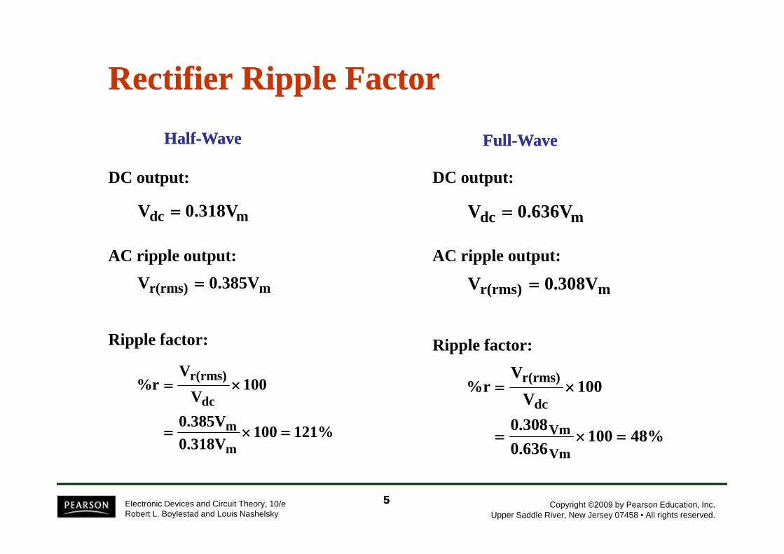
Rectifier Ripple FactorRectifier Ripple Factor
mdc 0.636VV ====
0.308VV ====
mdc 0.318VV ====
0.385VV ====
HalfHalf--WaveWave
DC output:
AC ripple output:
FullFull--WaveWave
DC output:
AC ripple output:
Copyright ©2009 by Pearson Education, Inc.Upper Saddle River, New Jersey 07458 • All rights reserved.
Electronic Devices and Circuit Theory, 10/eRobert L. Boylestad and Louis Nashelsky
%481000.636
0.308
100V
V%r
Vm
Vm
dc
r(rms)
====××××====
××××====
mr(rms) 0.308VV ====mr(rms) 0.385VV ====
121%1000.318V0.385V
100V
V%r
m
m
dc
r(rms)
====××××====
××××====
55
Ripple factor: Ripple factor:
Types of Filter CircuitsTypes of Filter CircuitsTypes of Filter CircuitsTypes of Filter CircuitsTypes of Filter CircuitsTypes of Filter CircuitsTypes of Filter CircuitsTypes of Filter Circuits
Capacitor FilterCapacitor FilterRC FilterRC Filter
Copyright ©2009 by Pearson Education, Inc.Upper Saddle River, New Jersey 07458 • All rights reserved.
Electronic Devices and Circuit Theory, 10/eRobert L. Boylestad and Louis Nashelsky
66

Capacitor FilterCapacitor FilterCapacitor FilterCapacitor FilterCapacitor FilterCapacitor FilterCapacitor FilterCapacitor Filter
The larger the capacitor the smaller the ripple voltage.
CR
2.4V
C
2.4I
fC34
IV
L
dcdcdcr(rms) ============
Ripple voltageRipple voltage
Copyright ©2009 by Pearson Education, Inc.Upper Saddle River, New Jersey 07458 • All rights reserved.
Electronic Devices and Circuit Theory, 10/eRobert L. Boylestad and Louis Nashelsky
C
4.17IV
4fC
IVV dc
mdc
mdc −−−−====−−−−====
DC outputDC output
100RLC2.4
100CV
2.4I100
V
V%r
dc
dc
dc
r(rms)××××====××××====××××====
Ripple factorRipple factor
77

Diode Ratings with Capacitor FilterDiode Ratings with Capacitor FilterDiode Ratings with Capacitor FilterDiode Ratings with Capacitor FilterDiode Ratings with Capacitor FilterDiode Ratings with Capacitor FilterDiode Ratings with Capacitor FilterDiode Ratings with Capacitor Filter
The size of the capacitor increases the current drawn through the diodes—the larger the capacitance, the greater the amount of current.
Peak Current vs. Capacitance:
tCV
I ====
where
Copyright ©2009 by Pearson Education, Inc.Upper Saddle River, New Jersey 07458 • All rights reserved.
Electronic Devices and Circuit Theory, 10/eRobert L. Boylestad and Louis Nashelsky
whereC = capacitanceV = change in capacitor voltage during charge/discharget = the charge/discharge time
88

RC Filter CircuitRC Filter CircuitRC Filter CircuitRC Filter CircuitRC Filter CircuitRC Filter CircuitRC Filter CircuitRC Filter Circuit
Adding an RC section further reduces the ripple voltage and decrease the surge current through the diodes.
r(rms)C
r(rms) VR
XV ≈≈≈≈′′′′
Copyright ©2009 by Pearson Education, Inc.Upper Saddle River, New Jersey 07458 • All rights reserved.
Electronic Devices and Circuit Theory, 10/eRobert L. Boylestad and Louis Nashelsky
V′′′′r(rms) = ripple voltage after the RC filterVr(rms) = ripple voltage before the RC filterR = resistor in the added RC filterXC = reactance of the capacitor in the added RC filter
100%V
VV%V
FL
FLNLR ××××
−−−−====
VNL = no-load voltageVFL = full-load voltage
99

Voltage Regulation CircuitsVoltage Regulation CircuitsVoltage Regulation CircuitsVoltage Regulation CircuitsVoltage Regulation CircuitsVoltage Regulation CircuitsVoltage Regulation CircuitsVoltage Regulation Circuits
There are two common types of circuitry for voltage regulation:
• Discrete Transistors• IC’s
Copyright ©2009 by Pearson Education, Inc.Upper Saddle River, New Jersey 07458 • All rights reserved.
Electronic Devices and Circuit Theory, 10/eRobert L. Boylestad and Louis Nashelsky
1010

DiscreteDiscreteDiscreteDiscreteDiscreteDiscreteDiscreteDiscrete--------Transistor RegulatorsTransistor RegulatorsTransistor RegulatorsTransistor RegulatorsTransistor RegulatorsTransistor RegulatorsTransistor RegulatorsTransistor Regulators
Series voltage regulatorSeries voltage regulatorCurrentCurrent--limiting circuitlimiting circuitShunt voltage regulatorShunt voltage regulator
Copyright ©2009 by Pearson Education, Inc.Upper Saddle River, New Jersey 07458 • All rights reserved.
Electronic Devices and Circuit Theory, 10/eRobert L. Boylestad and Louis Nashelsky
1111

Series Voltage Regulator CircuitSeries Voltage Regulator CircuitSeries Voltage Regulator CircuitSeries Voltage Regulator CircuitSeries Voltage Regulator CircuitSeries Voltage Regulator CircuitSeries Voltage Regulator CircuitSeries Voltage Regulator Circuit
Copyright ©2009 by Pearson Education, Inc.Upper Saddle River, New Jersey 07458 • All rights reserved.
Electronic Devices and Circuit Theory, 10/eRobert L. Boylestad and Louis Nashelsky
The series element controls the amount of the input voltage that gets to the output.
If the output voltage increases (or decreases), the comparator circuit provides a control signal to cause the series control element to decrease (or increase) the amount of the output voltage.
1212

Series Voltage Regulator CircuitSeries Voltage Regulator CircuitSeries Voltage Regulator CircuitSeries Voltage Regulator CircuitSeries Voltage Regulator CircuitSeries Voltage Regulator CircuitSeries Voltage Regulator CircuitSeries Voltage Regulator Circuit
• R1 and R2 act as the sampling circuit• Zener provides the reference voltage• Q2 controls the base current to Q1• Q1 maintains the constant output
voltage
Copyright ©2009 by Pearson Education, Inc.Upper Saddle River, New Jersey 07458 • All rights reserved.
Electronic Devices and Circuit Theory, 10/eRobert L. Boylestad and Louis Nashelsky
When the output increases:When the output increases:
1. The voltage at V2 and VBE of Q2increases
2. The conduction of Q2 increases3. The conduction of Q1 decreases4. The output voltage decreases
When the output decreases:When the output decreases:
1. The voltage at V2 and VBE of Q2decreases
2. The conduction of Q2 decreases3. The conduction of Q1 increases4. The output voltage increases
1313
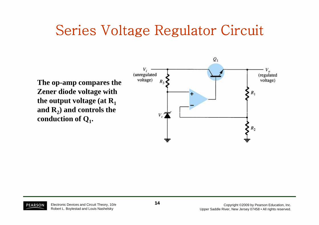
Series Voltage Regulator CircuitSeries Voltage Regulator CircuitSeries Voltage Regulator CircuitSeries Voltage Regulator CircuitSeries Voltage Regulator CircuitSeries Voltage Regulator CircuitSeries Voltage Regulator CircuitSeries Voltage Regulator Circuit
The op-amp compares the Zener diode voltage with the output voltage (at R1and R2) and controls the
Copyright ©2009 by Pearson Education, Inc.Upper Saddle River, New Jersey 07458 • All rights reserved.
Electronic Devices and Circuit Theory, 10/eRobert L. Boylestad and Louis Nashelsky
and R2) and controls the conduction of Q1.
1414

CurrentCurrentCurrentCurrentCurrentCurrentCurrentCurrent--------Limiting CircuitLimiting CircuitLimiting CircuitLimiting CircuitLimiting CircuitLimiting CircuitLimiting CircuitLimiting Circuit
Copyright ©2009 by Pearson Education, Inc.Upper Saddle River, New Jersey 07458 • All rights reserved.
Electronic Devices and Circuit Theory, 10/eRobert L. Boylestad and Louis Nashelsky
When IL increases:
• The voltage across RSC increases• The increasing voltage across RSC drives Q2 on• Conduction of Q2 reduces current for Q1 and the load
1515

Shunt Voltage Regulator CircuitShunt Voltage Regulator CircuitShunt Voltage Regulator CircuitShunt Voltage Regulator CircuitShunt Voltage Regulator CircuitShunt Voltage Regulator CircuitShunt Voltage Regulator CircuitShunt Voltage Regulator Circuit
The shunt voltage regulator shunts current away from the load.
Copyright ©2009 by Pearson Education, Inc.Upper Saddle River, New Jersey 07458 • All rights reserved.
Electronic Devices and Circuit Theory, 10/eRobert L. Boylestad and Louis Nashelsky
The load voltage is sampled and fed back to a comparator circuit. If the load voltage is too high, control circuitry shunts more current away from the load.
1616

Shunt Voltage Regulator CircuitShunt Voltage Regulator CircuitShunt Voltage Regulator CircuitShunt Voltage Regulator CircuitShunt Voltage Regulator CircuitShunt Voltage Regulator CircuitShunt Voltage Regulator CircuitShunt Voltage Regulator Circuit
Copyright ©2009 by Pearson Education, Inc.Upper Saddle River, New Jersey 07458 • All rights reserved.
Electronic Devices and Circuit Theory, 10/eRobert L. Boylestad and Louis Nashelsky
When the output voltage increases:
• The Zener current increases• The conduction of Q2 increases• The voltage drop at Rs increases• The output voltage decreases
When the output voltage decreases:
• The Zener current decreases• The conduction of Q2 decreases• The voltage drop at Rs decreases• The output voltage increases
1717

Shunt Voltage Regulator CircuitShunt Voltage Regulator CircuitShunt Voltage Regulator CircuitShunt Voltage Regulator CircuitShunt Voltage Regulator CircuitShunt Voltage Regulator CircuitShunt Voltage Regulator CircuitShunt Voltage Regulator Circuit
Copyright ©2009 by Pearson Education, Inc.Upper Saddle River, New Jersey 07458 • All rights reserved.
Electronic Devices and Circuit Theory, 10/eRobert L. Boylestad and Louis Nashelsky
1818

IC Voltage RegulatorsIC Voltage RegulatorsIC Voltage RegulatorsIC Voltage RegulatorsIC Voltage RegulatorsIC Voltage RegulatorsIC Voltage RegulatorsIC Voltage Regulators
Regulator ICs contain:
• Comparator circuit• Reference voltage• Control circuitry• Overload protection
Copyright ©2009 by Pearson Education, Inc.Upper Saddle River, New Jersey 07458 • All rights reserved.
Electronic Devices and Circuit Theory, 10/eRobert L. Boylestad and Louis Nashelsky
Types of three-terminal IC voltage regulators
• Fixed positive voltage regulator• Fixed negative voltage regulator• Adjustable voltage regulator
1919

ThreeThree--Terminal Voltage RegulatorsTerminal Voltage Regulators
Copyright ©2009 by Pearson Education, Inc.Upper Saddle River, New Jersey 07458 • All rights reserved.
Electronic Devices and Circuit Theory, 10/eRobert L. Boylestad and Louis Nashelsky
The specifications for this IC indicate:
• The range of input voltages that can be regulated for a specific range of output voltage and load current
• Load regulation—variation in output voltage with variations in load current
• Line regulation—variation in output voltage with variations in inputvoltagevoltagevoltagevoltage
2020

Fixed Positive Voltage RegulatorFixed Positive Voltage RegulatorFixed Positive Voltage RegulatorFixed Positive Voltage RegulatorFixed Positive Voltage RegulatorFixed Positive Voltage RegulatorFixed Positive Voltage RegulatorFixed Positive Voltage Regulator
Copyright ©2009 by Pearson Education, Inc.Upper Saddle River, New Jersey 07458 • All rights reserved.
Electronic Devices and Circuit Theory, 10/eRobert L. Boylestad and Louis Nashelsky
These ICs provide a fixed positive output voltage.
2121

Fixed Negative Voltage RegulatorFixed Negative Voltage RegulatorFixed Negative Voltage RegulatorFixed Negative Voltage RegulatorFixed Negative Voltage RegulatorFixed Negative Voltage RegulatorFixed Negative Voltage RegulatorFixed Negative Voltage Regulator
Copyright ©2009 by Pearson Education, Inc.Upper Saddle River, New Jersey 07458 • All rights reserved.
Electronic Devices and Circuit Theory, 10/eRobert L. Boylestad and Louis Nashelsky
These ICs output a fixed negative output voltage.
2222

Adjustable Voltage RegulatorAdjustable Voltage RegulatorAdjustable Voltage RegulatorAdjustable Voltage RegulatorAdjustable Voltage RegulatorAdjustable Voltage RegulatorAdjustable Voltage RegulatorAdjustable Voltage Regulator
These regulators have adjustable output voltages.
The output voltage is
Copyright ©2009 by Pearson Education, Inc.Upper Saddle River, New Jersey 07458 • All rights reserved.
Electronic Devices and Circuit Theory, 10/eRobert L. Boylestad and Louis Nashelsky
The output voltage is commonly selected using a potentiometer.
2323

Practical Power SuppliesPractical Power SuppliesPractical Power SuppliesPractical Power SuppliesPractical Power SuppliesPractical Power SuppliesPractical Power SuppliesPractical Power Supplies
DC supply (linear power supplies)DC supply (linear power supplies)Chopper supply (switching power supplies)Chopper supply (switching power supplies)
TV horizontal high voltage supplyTV horizontal high voltage supplyBattery chargersBattery chargers
Copyright ©2009 by Pearson Education, Inc.Upper Saddle River, New Jersey 07458 • All rights reserved.
Electronic Devices and Circuit Theory, 10/eRobert L. Boylestad and Louis Nashelsky
2424