colibri. universal battery power tool system for use...
TRANSCRIPT
Instructions for Use
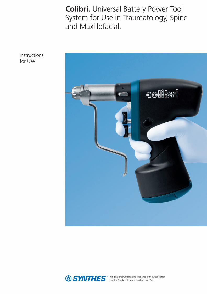
Colibri. Universal Battery Power ToolSystem for Use in Traumatology, Spineand Maxillofacial.

Synthes 1
Contents
Introduction
Using the Colibri
Care and Maintenance
Troubleshooting
Ordering Information
General Information 2
System Specifications 3
Handpiece 4
Use 6
Attachments 10
General Information 21
Preparation for Cleaning and Disinfection 22
Cleaning and Disinfection 23
Lubrication 25
Inspection and Sterilization 27
28
30
Cd
Ni-Cd
2 Synthes Colibri Instructions for Use
Introduction
Intended UseThe Colibri is a battery-driven power tool for use in trauma-tology, maxillofacial and spinal column surgery. To ensureproper operation of the Colibri, use only Synthes original ac-cessories.
Patient safetyThe Colibri may only be used on patients after the medicalpersonnel have read the instructions. Since it is impossible to fully exclude the possibility of technical problems, alwaysensure that an alternative system is ready when using theunit on patients.
Starting the systemNew power tools and their accessories must undergo theentire reprocessing process before being used. Completelyremove protective caps and films.
Caution – The batteries may never be sterilized. Explosion hazard!– To prevent injury, the power tool must be locked with the
safety system when coupling and removing attachmentsand tools, and before laying it down (see page 4).
– Properly operating cutting tools are essential to the successof an operation. For this reason, cutting tools must bechecked for wear and/or damage after each use andreplaced if necessary. For each operation, we recommendusing a new Synthes original cutting tool.
MaintenanceThe life of the equipment can be substantially extended by following the service instructions.
For the devices to function properly, Synthes recommendsthat they be serviced annually by Synthes, or by exclusiveSynthes sales outlets.
Synthes is not responsible for damage arising from improperuse or technical service rendered by unauthorized parties.
Additional information on the use and preparation of theproducts can be obtained from a Synthes representative.
Particular attention should be given to the section “Care and Maintenance“ starting on page 21.
Liability of the userThe user of the product is liable for proper use of the equip-ment during surgery.
Explanation of symbols usedThis symbol provides notification of important infor-mation. When this symbol is on a device, it refers to important information in the accompanying docu-ments.
This symbol indicates that the corresponding devicemay not be immersed in liquids.
The device is classified as type BF against electricalshock and leakage current. The device is suitable foruse on patients according to the standards defined by CSA 601.1, IEC 60601-1 and UL 2601.
This symbol indicates that the battery containsrechargeable NiCd (nickel cadmium) cells. The batteryis recyclable (observe the following instructions).
Since they contain cadmium, batteries may not be disposed with household garbage. Dispose or recyclethe batteries in accordance with local and nationalregulations.
General Information
Synthes 3
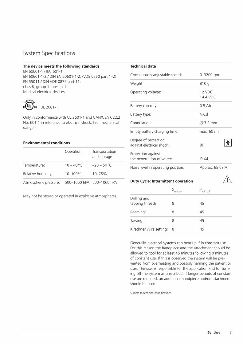
Technical data
Continuously adjustable speed: 0–3200 rpm
Weight 810 g
Operating voltage: 12 VDC14.4 VDC
Battery capacity: 0.5 Ah
Battery type: NiCd
Cannulation: � 3.2 mm
Empty battery charging time: max. 60 min.
Degree of protection against electrical shock: BF
Protection against the penetration of water: IP X4
Noise level in operating position: Approx. 65 dB(A)
Duty Cycle: Intermittent operation
Xmin on Ymin off
Drilling and tapping threads: 8 45
Reaming: 8 45
Sawing: 8 45
Kirschner Wire setting: 8 45
Generally, electrical systems can heat up if in constant use.For this reason the handpiece and the attachment should beallowed to cool for at least 45 minutes following 8 minutesof constant use. If this is observed the system will be pre-vented from overheating and possibly harming the patient oruser. The user is responsible for the application and for turn-ing off the system as prescribed. If longer periods of constantuse are required, an additional handpiece and/or attachmentshould be used.
Subject to technical modifications.
The device meets the following standardsEN 60601-1 / IEC 601-1EN 60601-1-2 / DIN EN 60601-1-2, (VDE 0750 part 1–2) EN 55011 / DIN VDE 0875 part 11, class B, group 1 thresholdsMedical electrical devices
UL 2601-1
Only in conformance with UL 2601-1 and CAN/CSA C22.2No. 601.1 in reference to electrical shock, fire, mechanicaldanger.
Environmental conditions
Operation Transportation and storage
Temperature: 10 – 40 °C –20 – 50 °C
Relative humidity: 10–100% 10–75%
Atmospheric pressure: 500–1060 hPA 500–1060 hPA
May not be stored or operated in explosive atmospheres
System Specifications
� �
�
�
�
�
�
�
�
�
�
�
Using the Colibri
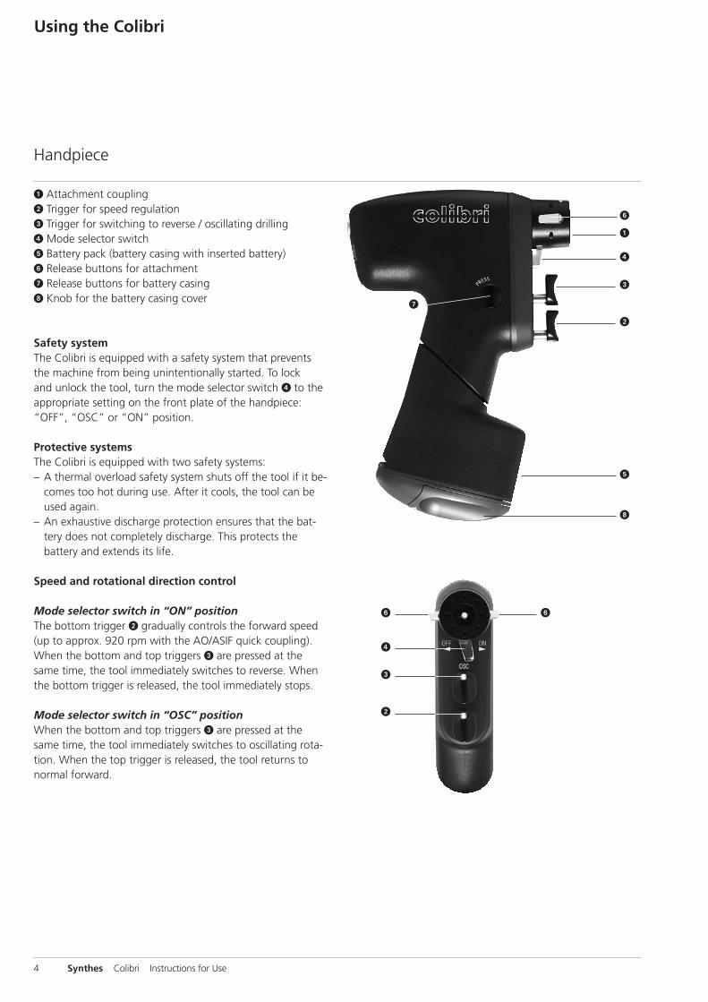
� Attachment coupling � Trigger for speed regulation� Trigger for switching to reverse / oscillating drilling� Mode selector switch � Battery pack (battery casing with inserted battery) � Release buttons for attachment Release buttons for battery casing� Knob for the battery casing cover
Safety system The Colibri is equipped with a safety system that preventsthe machine from being unintentionally started. To lock and unlock the tool, turn the mode selector switch � to theappropriate setting on the front plate of the handpiece:“OFF”, “OSC” or “ON” position.
Protective systemsThe Colibri is equipped with two safety systems:– A thermal overload safety system shuts off the tool if it be-
comes too hot during use. After it cools, the tool can beused again.
– An exhaustive discharge protection ensures that the bat-tery does not completely discharge. This protects thebattery and extends its life.
Speed and rotational direction control
Mode selector switch in “ON” positionThe bottom trigger � gradually controls the forward speed(up to approx. 920 rpm with the AO/ASIF quick coupling).When the bottom and top triggers � are pressed at thesame time, the tool immediately switches to reverse. Whenthe bottom trigger is released, the tool immediately stops.
Mode selector switch in “OSC” positionWhen the bottom and top triggers � are pressed at thesame time, the tool immediately switches to oscillating rota-tion. When the top trigger is released, the tool returns tonormal forward.
4 Synthes Colibri Instructions for Use
Handpiece
Synthes 5
Important notes– To prevent injury, the machine must be locked with the
mode selector switch � when coupling and removingattachments and tools, and before laying it down (see page 4).
– Never place the Colibri on a magnetic surface since themachine might start unintentionally.
– Pay particular attention to all instructions in the individualsections that are identified with “Caution”.
– Components that are no longer useful must be disposed of in accordance with local and national regulations.
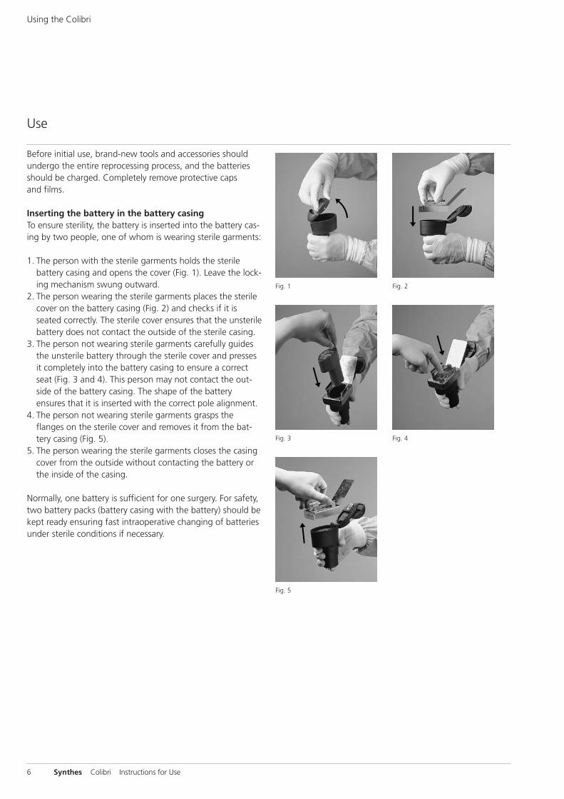
Fig. 5
Fig. 3 Fig. 4
Fig. 2Fig. 1
6 Synthes Colibri Instructions for Use
Using the Colibri
Use
Before initial use, brand-new tools and accessories shouldundergo the entire reprocessing process, and the batteriesshould be charged. Completely remove protective caps and films.
Inserting the battery in the battery casingTo ensure sterility, the battery is inserted into the battery cas-ing by two people, one of whom is wearing sterile garments:
1. The person with the sterile garments holds the sterilebattery casing and opens the cover (Fig. 1). Leave the lock-ing mechanism swung outward.
2. The person wearing the sterile garments places the sterilecover on the battery casing (Fig. 2) and checks if it isseated correctly. The sterile cover ensures that the unsterilebattery does not contact the outside of the sterile casing.
3. The person not wearing sterile garments carefully guidesthe unsterile battery through the sterile cover and pressesit completely into the battery casing to ensure a correctseat (Fig. 3 and 4). This person may not contact the out-side of the battery casing. The shape of the batteryensures that it is inserted with the correct pole alignment.
4. The person not wearing sterile garments grasps theflanges on the sterile cover and removes it from the bat-tery casing (Fig. 5).
5. The person wearing the sterile garments closes the casingcover from the outside without contacting the battery orthe inside of the casing.
Normally, one battery is sufficient for one surgery. For safety,two battery packs (battery casing with the battery) should bekept ready ensuring fast intraoperative changing of batteriesunder sterile conditions if necessary.

Synthes 7
Fig. 6
Fig. 7
Caution– If the unsterile battery contacts the outside of the casing,
the casing must be resterilised before being used in theOR.
– To close the casing cover, press it firmly to ensure that it iscompletely closed (Fig. 6 and 7) so that the locking mecha-nism properly engages.
– Sterilize the sterile cover after each use to ensure asepticconditions when inserting the unsterile battery into thesterile battery casing.
Inserting the battery pack into the power toolGuide the battery pack (battery casing with inserted battery)from below into the shaft of the handpiece (Fig. 8). Theshape of the battery casing prevents the battery from beinginserted incorrectly. Check if the battery pack is seated cor-rectly by gently pulling on it.
Removing the battery pack from the power tool.Simultaneously press the release buttons for the batterycasing with one hand (Fig. 9), and use the other hand to remove the battery pack from the handpiece.
Fig. 8 Fig. 9
8 Synthes Colibri Instructions for Use
Using the Colibri
Charging, storing and using batteries
Charging– The batteries should always be charged before use.– Only use chargers recommended by Synthes to charge the
batteries. Using a charger that does not originate fromSynthes can damage the battery.
– Charge the batteries within an ambient temperature rangeof 0 °C to 40 °C.
Storage– When the battery is not being used, store it in the appro-
priate Synthes charger. This will keep it from discharging, and the battery will be fully charged and ready to use.
– Before first use or after storing the battery outside of thecharger for more than one month, up to five charging/discharging cycles may be necessary for the battery to befully charged.
– The charging station should always be turned on when abattery is in the charging base. This ensures availability andprevents discharge.
Use– Only insert the battery pack directly before using the
Colibri. This saves battery energy and prevents having tochange it during surgery.
– Never open the battery casing during surgery.– Only use batteries for the indicated purpose. – The Colibri 14.4 VDC battery (532.033) may not be used
in oscillating mode since this could damage the motor and gears. For this mode, always use the standard 12 VDCbattery (532.003).
– Only use the 14.4 VDC Colibri battery with the attach-ments marked with a * on pages 16 and 17.
– Do not transport or store the batteries together with mate-rials that conduct electricity and can cause a short. Thiscan damage the battery and generate heat which cancause burns.
– Never expose batteries to temperatures above 60 °C.– Do not apply force to the batteries, and do not let them
fall.– Never use damaged batteries; they can damage the power
tool.– Follow the additional information in the section “Care and
Maintenance“ starting on page 21 as well as the Instruc-tions for Use of the Synthes Universal Battery Charger(036.000.725).
Synthes 9
Using the Colibri with mains currentThe Colibri can also be operated with mains current. Whenthe Colibri is operated with mains current it is classified astype B against electrical shock and leakage current. Whenoperated with mains current use the corresponding adapter(Art. 05.001.024) and an electrical console belonging to the Electric Pen Drive (Art. 05.001.000, 05.001.001 or05.001.002). The adapter can be inserted into the Colibrihandpiece and removed like a battery pack as describedabove. Also follow the Electric Pen Drive’s Instructions forUse (036.000.800).
“Oscillating drilling” modeTo protect soft tissue when drilling and inserting Kirschnerwires, the Colibri has an electronically controlled oscillatingmode.
To preset the oscillating mode, switch the mode selectorswitch to “OSC“ position.
Pressing the bottom trigger by itself causes the tool to rotateclockwise as usual. Simultaneously pressing the top andbottom triggers causes the tool to immediately switch to os-cillating mode. The clamped tool oscillates clockwise/anti-clockwise. The speed can be changed by means of the bot-tom trigger. After the top trigger is released, the tool returnsto normal clockwise rotation.
Caution– Oscillating mode may only be switched on with the
following attachments:– AO/ASIF Quick Coupling (532.013) – Jacobs Chuck (532.014, 532.016) – Quick Coupling for Kirschner Wires (532.022)
– You can only switch to reverse by turning the modeselector switch to “ON” position.
– The maximum cutting speed of an attachment is less in oscillation mode than in normal mode.
Using the Colibri
10 Synthes Colibri Instructions for Use
Attachments
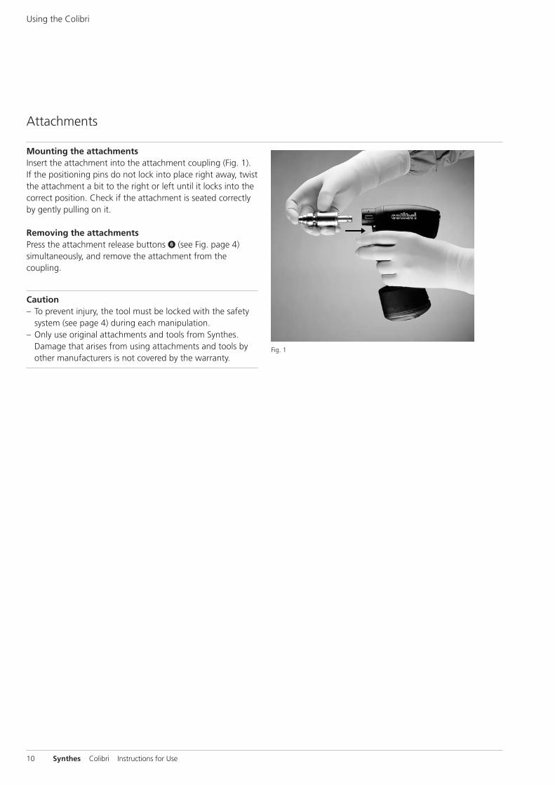
Mounting the attachmentsInsert the attachment into the attachment coupling (Fig. 1).If the positioning pins do not lock into place right away, twistthe attachment a bit to the right or left until it locks into thecorrect position. Check if the attachment is seated correctlyby gently pulling on it.
Removing the attachments Press the attachment release buttons � (see Fig. page 4)simultaneously, and remove the attachment from thecoupling.
Caution – To prevent injury, the tool must be locked with the safety
system (see page 4) during each manipulation. – Only use original attachments and tools from Synthes.
Damage that arises from using attachments and tools byother manufacturers is not covered by the warranty.
Fig. 1

Synthes 11
�
�
�
Quick Coupling for Kirschner Wires (532.022) (Speed: 0–800 rpm)
Kirschner Wires of any length with a diameter of0.6–3.2 mm can be used with the Quick Coupling forKirschner Wires.
1. Adjust the Kirschner Wire diameter according to the labelon the adjusting sleeve �. Slightly press the adjustingsleeve axially against the tool and rotate the sleeve.
2. Apply a slight amount of pressure to insert the KirschnerWire from the front or back into the cannulation �. The wire is held automatically.
3. Adjust the working length by pulling on the wire. 4. To affix the wire, pull the tension lever � against the tool
with your little finger and ring finger. Only pull the tensionlever against the tool as much as necessary. The clampingforce can be varied by pulling and releasing the clampinglever.
5. Insert the wire into the bone. Apply the clamping force as long as the wire is advanced.
6. To adjust the grip on the wire, reduce the clamping forceand move the tool to the desired length. Reclamp the wireby pulling on the tension lever.
Using the Colibri
12 Synthes Colibri Instructions for Use
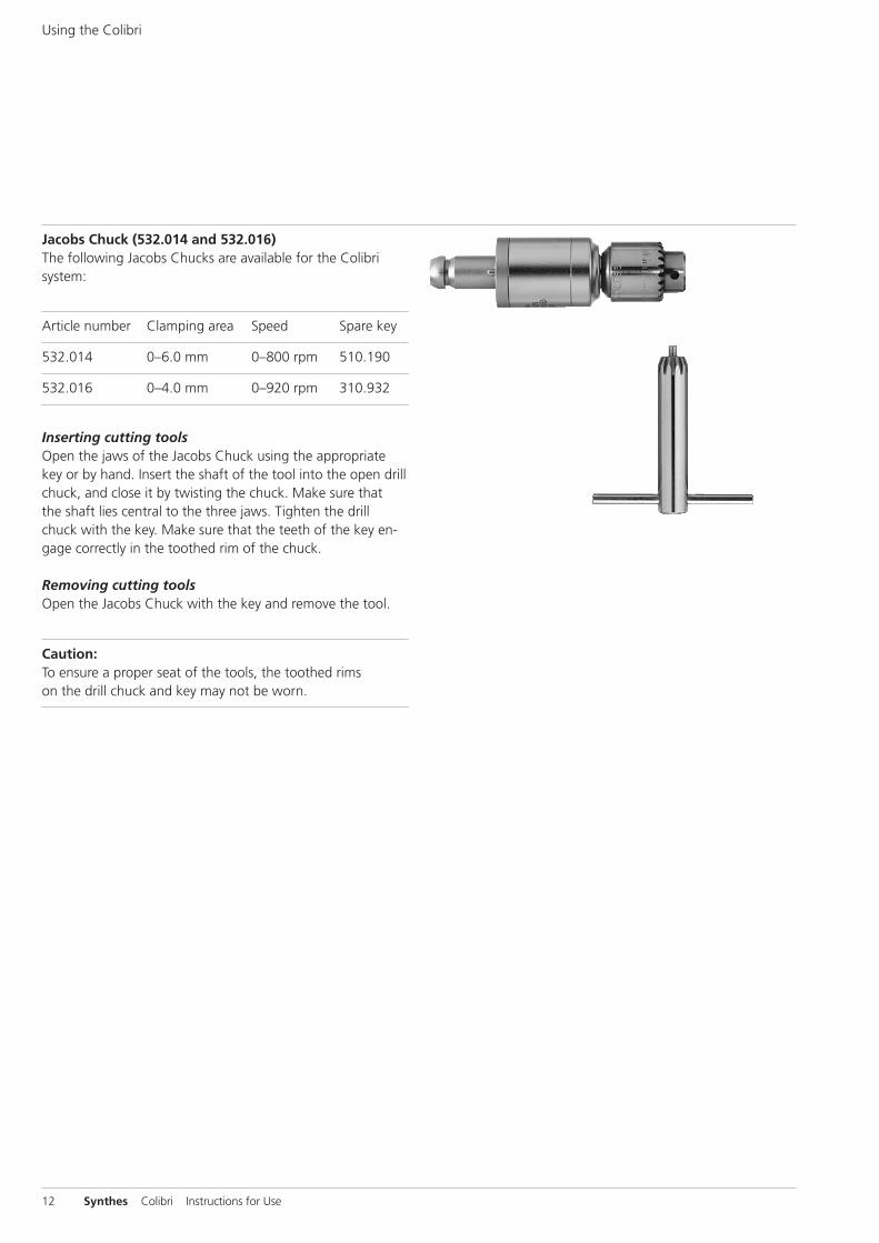
Jacobs Chuck (532.014 and 532.016)The following Jacobs Chucks are available for the Colibrisystem:
Article number Clamping area Speed Spare key
532.014 0–6.0 mm 0–800 rpm 510.190
532.016 0–4.0 mm 0–920 rpm 310.932
Inserting cutting tools Open the jaws of the Jacobs Chuck using the appropriatekey or by hand. Insert the shaft of the tool into the open drillchuck, and close it by twisting the chuck. Make sure that the shaft lies central to the three jaws. Tighten the drillchuck with the key. Make sure that the teeth of the key en-gage correctly in the toothed rim of the chuck.
Removing cutting tools Open the Jacobs Chuck with the key and remove the tool.
Caution: To ensure a proper seat of the tools, the toothed rims on the drill chuck and key may not be worn.
Synthes 13
��
Fig. 1
Fig. 2
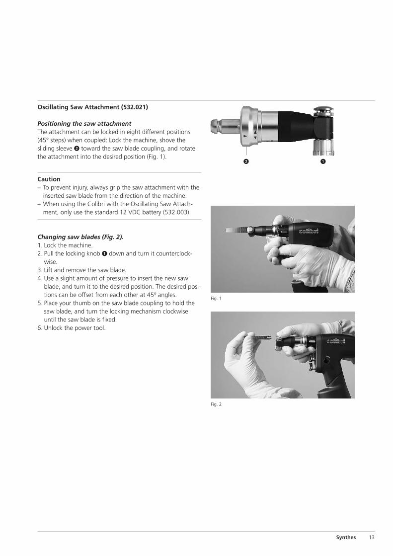
Oscillating Saw Attachment (532.021)
Positioning the saw attachmentThe attachment can be locked in eight different positions(45° steps) when coupled: Lock the machine, shove thesliding sleeve � toward the saw blade coupling, and rotatethe attachment into the desired position (Fig. 1).
Caution– To prevent injury, always grip the saw attachment with the
inserted saw blade from the direction of the machine.– When using the Colibri with the Oscillating Saw Attach-
ment, only use the standard 12 VDC battery (532.003).
Changing saw blades (Fig. 2). 1. Lock the machine. 2. Pull the locking knob � down and turn it counterclock-
wise. 3. Lift and remove the saw blade. 4. Use a slight amount of pressure to insert the new saw
blade, and turn it to the desired position. The desired posi-tions can be offset from each other at 45º angles.
5. Place your thumb on the saw blade coupling to hold thesaw blade, and turn the locking mechanism clockwiseuntil the saw blade is fixed.
6. Unlock the power tool.
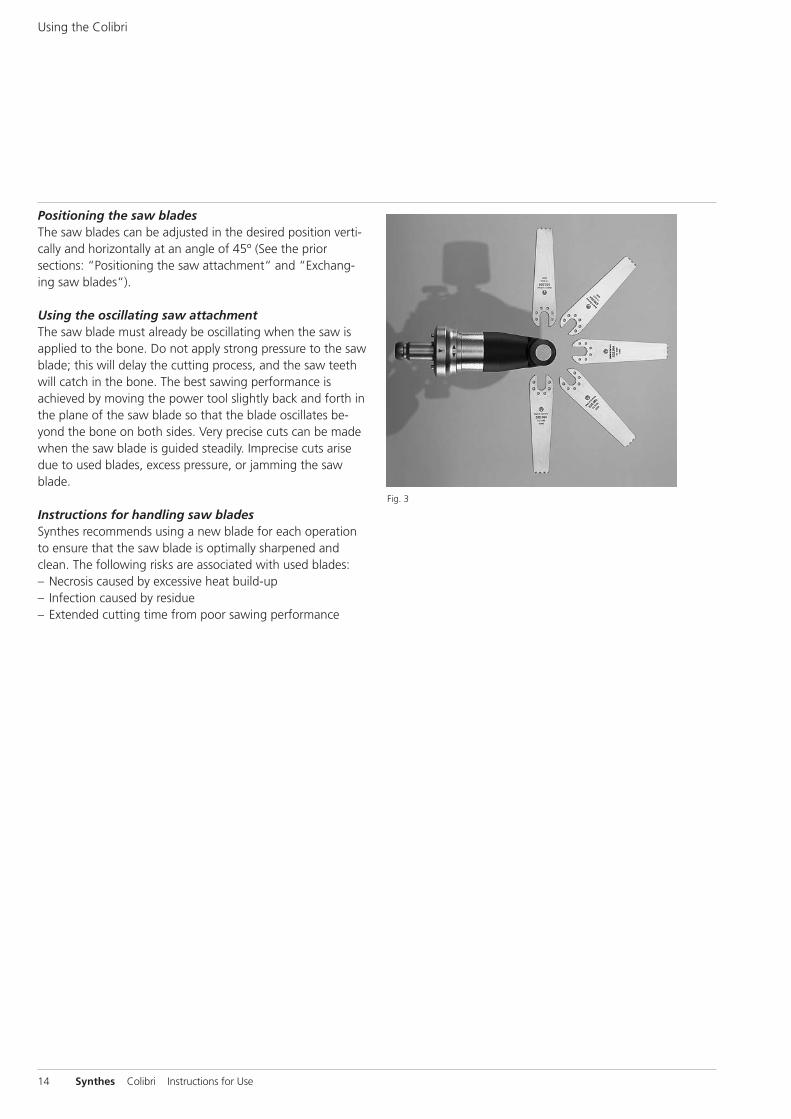
Fig. 3
14 Synthes Colibri Instructions for Use
Using the Colibri
Positioning the saw bladesThe saw blades can be adjusted in the desired position verti-cally and horizontally at an angle of 45º (See the priorsections: “Positioning the saw attachment“ and “Exchang-ing saw blades“).
Using the oscillating saw attachment The saw blade must already be oscillating when the saw isapplied to the bone. Do not apply strong pressure to the sawblade; this will delay the cutting process, and the saw teethwill catch in the bone. The best sawing performance isachieved by moving the power tool slightly back and forth inthe plane of the saw blade so that the blade oscillates be-yond the bone on both sides. Very precise cuts can be madewhen the saw blade is guided steadily. Imprecise cuts arisedue to used blades, excess pressure, or jamming the sawblade.
Instructions for handling saw bladesSynthes recommends using a new blade for each operationto ensure that the saw blade is optimally sharpened andclean. The following risks are associated with used blades: – Necrosis caused by excessive heat build-up– Infection caused by residue– Extended cutting time from poor sawing performance
Synthes 15
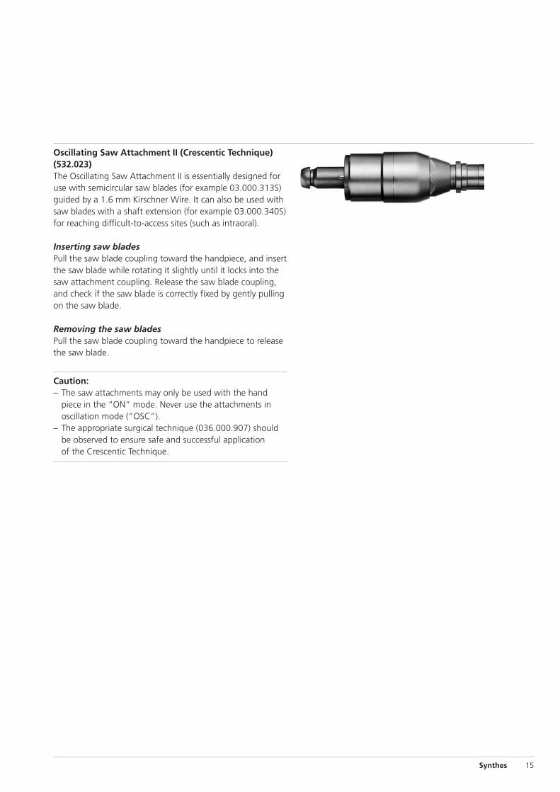
Oscillating Saw Attachment II (Crescentic Technique)(532.023)The Oscillating Saw Attachment II is essentially designed foruse with semicircular saw blades (for example 03.000.313S)guided by a 1.6 mm Kirschner Wire. It can also be used withsaw blades with a shaft extension (for example 03.000.340S)for reaching difficult-to-access sites (such as intraoral).
Inserting saw bladesPull the saw blade coupling toward the handpiece, and insertthe saw blade while rotating it slightly until it locks into thesaw attachment coupling. Release the saw blade coupling,and check if the saw blade is correctly fixed by gently pullingon the saw blade.
Removing the saw bladesPull the saw blade coupling toward the handpiece to releasethe saw blade.
Caution:– The saw attachments may only be used with the hand
piece in the “ON” mode. Never use the attachments inoscillation mode (“OSC“).
– The appropriate surgical technique (036.000.907) shouldbe observed to ensure safe and successful application of the Crescentic Technique.
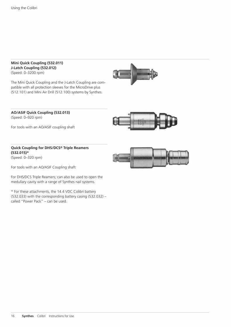
Mini Quick Coupling (532.011)J-Latch Coupling (532.012) (Speed: 0–3200 rpm)
The Mini Quick Coupling and the J-Latch Coupling are com-patible with all protection sleeves for the MicroDrive plus(512.101) and Mini Air Drill (512.100) systems by Synthes.
16 Synthes Colibri Instructions for Use
Using the Colibri
Quick Coupling for DHS/DCS® Triple Reamers(532.015)* (Speed: 0–320 rpm)
For tools with an AO/ASIF Coupling shaft
For DHS/DCS Triple Reamers; can also be used to open themedullary cavity with a range of Synthes nail systems.
* For these attachments, the 14.4 VDC Colibri battery(532.033) with the corresponding battery casing (532.032) –called “Power Pack” – can be used.
AO/ASIF Quick Coupling (532.013) (Speed: 0–920 rpm)
For tools with an AO/ASIF coupling shaft
Synthes 17
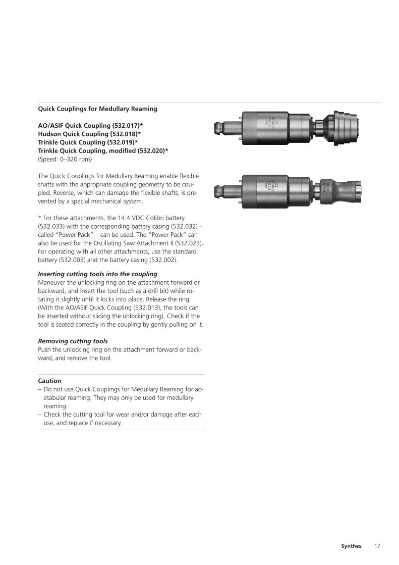
Quick Couplings for Medullary Reaming
AO/ASIF Quick Coupling (532.017)*Hudson Quick Coupling (532.018)*Trinkle Quick Coupling (532.019)*Trinkle Quick Coupling, modified (532.020)*(Speed: 0–320 rpm)
The Quick Couplings for Medullary Reaming enable flexibleshafts with the appropriate coupling geometry to be cou-pled. Reverse, which can damage the flexible shafts, is pre-vented by a special mechanical system.
* For these attachments, the 14.4 VDC Colibri battery(532.033) with the corresponding battery casing (532.032) –called “Power Pack” – can be used. The “Power Pack” canalso be used for the Oscillating Saw Attachment II (532.023).For operating with all other attachments, use the standardbattery (532.003) and the battery casing (532.002).
Inserting cutting tools into the couplingManeuver the unlocking ring on the attachment forward orbackward, and insert the tool (such as a drill bit) while ro-tating it slightly until it locks into place. Release the ring.(With the AO/ASIF Quick Coupling (532.013), the tools canbe inserted without sliding the unlocking ring). Check if thetool is seated correctly in the coupling by gently pulling on it.
Removing cutting toolsPush the unlocking ring on the attachment forward or back-ward, and remove the tool.
Caution– Do not use Quick Couplings for Medullary Reaming for ac-
etabular reaming. They may only be used for medullaryreaming.
– Check the cutting tool for wear and/or damage after eachuse, and replace if necessary.
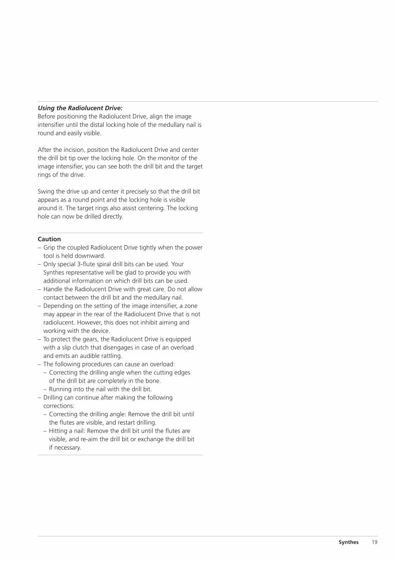
(511.300)(532.031)(532.013)
18 Synthes Colibri Instructions for Use
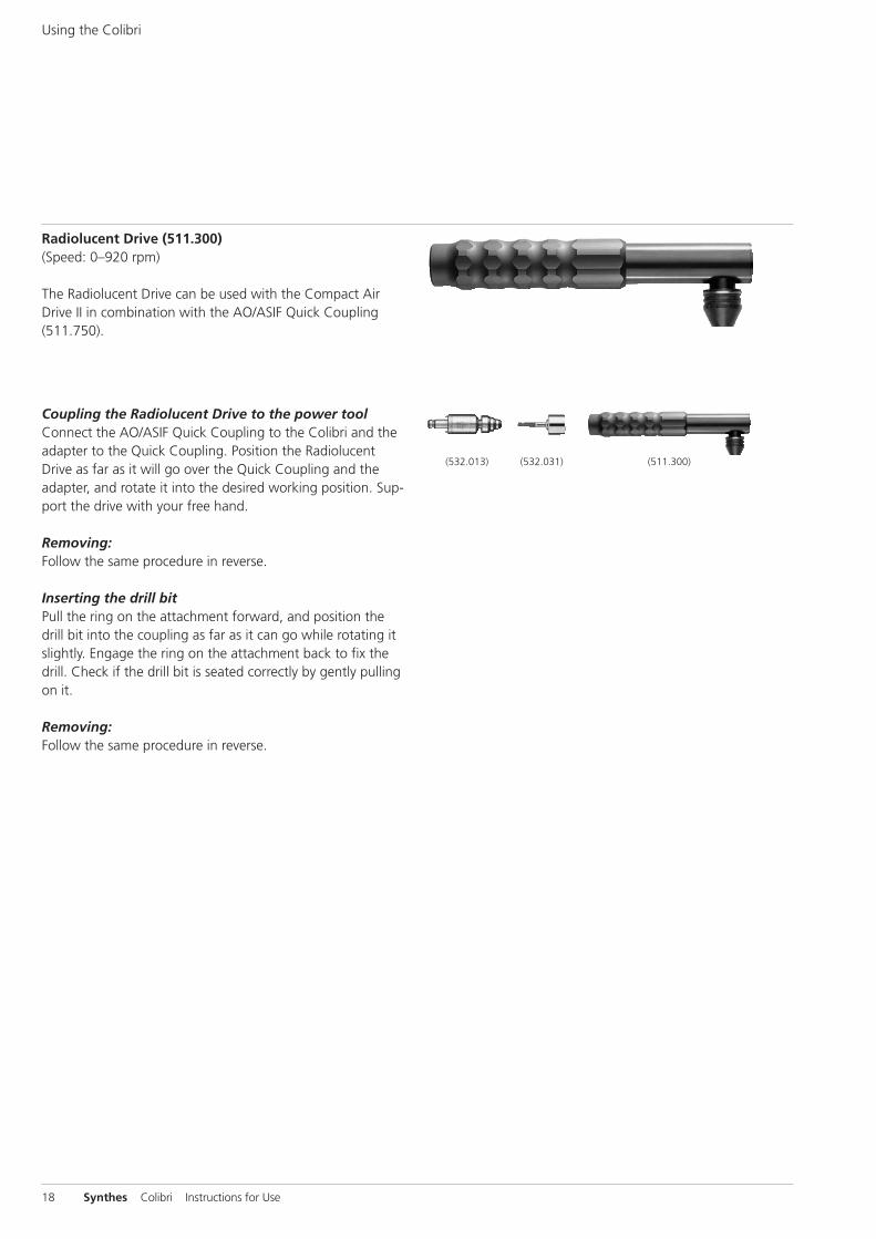
Radiolucent Drive (511.300) (Speed: 0–920 rpm)
The Radiolucent Drive can be used with the Compact AirDrive II in combination with the AO/ASIF Quick Coupling(511.750).
Coupling the Radiolucent Drive to the power toolConnect the AO/ASIF Quick Coupling to the Colibri and theadapter to the Quick Coupling. Position the RadiolucentDrive as far as it will go over the Quick Coupling and theadapter, and rotate it into the desired working position. Sup-port the drive with your free hand.
Removing:Follow the same procedure in reverse.
Inserting the drill bitPull the ring on the attachment forward, and position thedrill bit into the coupling as far as it can go while rotating itslightly. Engage the ring on the attachment back to fix thedrill. Check if the drill bit is seated correctly by gently pullingon it.
Removing:Follow the same procedure in reverse.
Using the Colibri
Synthes 19
Using the Radiolucent Drive:Before positioning the Radiolucent Drive, align the imageintensifier until the distal locking hole of the medullary nail isround and easily visible.
After the incision, position the Radiolucent Drive and centerthe drill bit tip over the locking hole. On the monitor of theimage intensifier, you can see both the drill bit and the targetrings of the drive.
Swing the drive up and center it precisely so that the drill bitappears as a round point and the locking hole is visiblearound it. The target rings also assist centering. The lockinghole can now be drilled directly.
Caution– Grip the coupled Radiolucent Drive tightly when the power
tool is held downward.– Only special 3-flute spiral drill bits can be used. Your
Synthes representative will be glad to provide you withadditional information on which drill bits can be used.
– Handle the Radiolucent Drive with great care. Do not allowcontact between the drill bit and the medullary nail.
– Depending on the setting of the image intensifier, a zonemay appear in the rear of the Radiolucent Drive that is notradiolucent. However, this does not inhibit aiming andworking with the device.
– To protect the gears, the Radiolucent Drive is equippedwith a slip clutch that disengages in case of an overloadand emits an audible rattling.
– The following procedures can cause an overload:– Correcting the drilling angle when the cutting edges
of the drill bit are completely in the bone. – Running into the nail with the drill bit.
– Drilling can continue after making the followingcorrections:– Correcting the drilling angle: Remove the drill bit until
the flutes are visible, and restart drilling. – Hitting a nail: Remove the drill bit until the flutes are
visible, and re-aim the drill bit or exchange the drill bit if necessary.
20 Synthes Colibri Instructions for Use
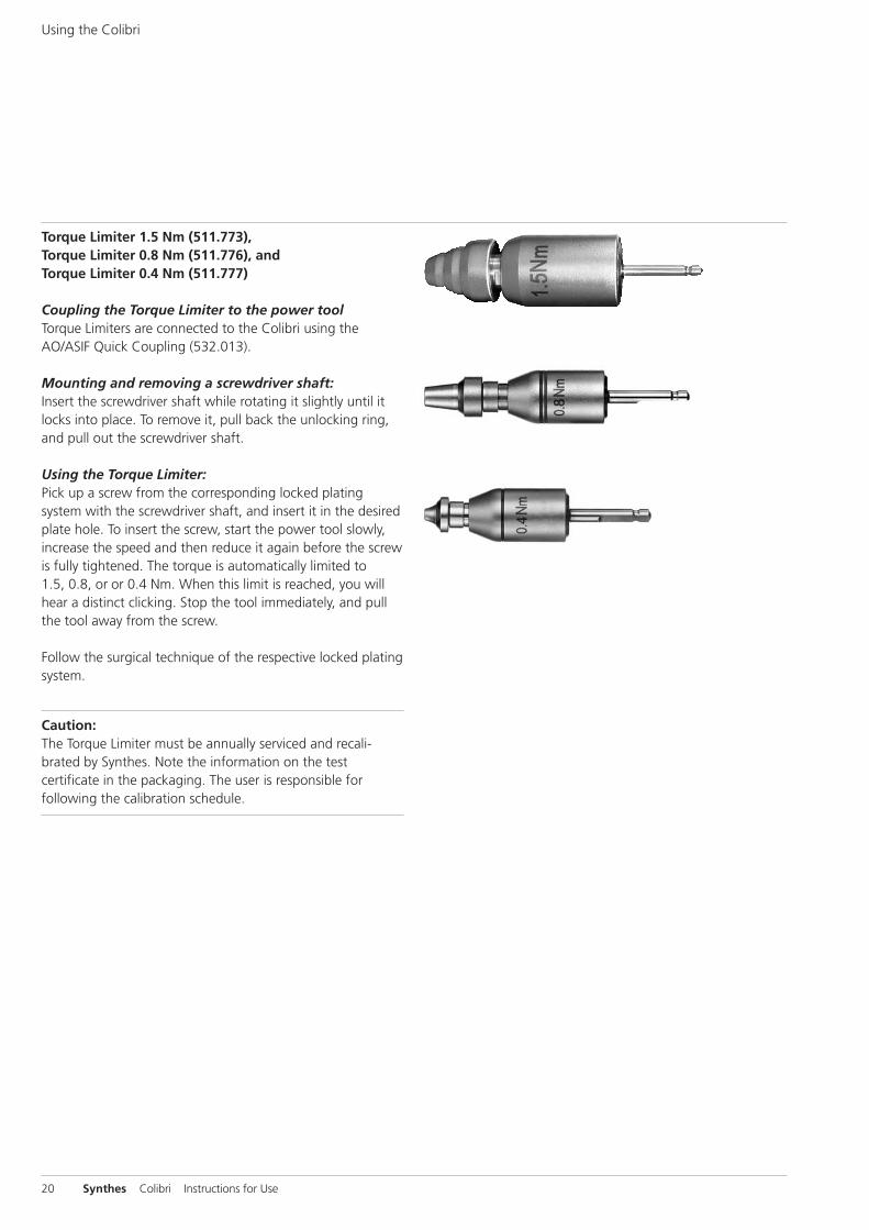
Torque Limiter 1.5 Nm (511.773),Torque Limiter 0.8 Nm (511.776), andTorque Limiter 0.4 Nm (511.777)
Coupling the Torque Limiter to the power toolTorque Limiters are connected to the Colibri using theAO/ASIF Quick Coupling (532.013).
Mounting and removing a screwdriver shaft:Insert the screwdriver shaft while rotating it slightly until itlocks into place. To remove it, pull back the unlocking ring,and pull out the screwdriver shaft.
Using the Torque Limiter:Pick up a screw from the corresponding locked platingsystem with the screwdriver shaft, and insert it in the desiredplate hole. To insert the screw, start the power tool slowly,increase the speed and then reduce it again before the screwis fully tightened. The torque is automatically limited to 1.5, 0.8, or or 0.4 Nm. When this limit is reached, you willhear a distinct clicking. Stop the tool immediately, and pullthe tool away from the screw.
Follow the surgical technique of the respective locked platingsystem.
Caution:The Torque Limiter must be annually serviced and recali-brated by Synthes. Note the information on the testcertificate in the packaging. The user is responsible forfollowing the calibration schedule.
Using the Colibri
Synthes 21
Care and Maintenance
Regular care and maintenance according to the followinginstructions (fulfilling DIN EN ISO 17664) can substantiallyincrease the reliability and life of the system components.Synthes recommends annual servicing and inspection by theoriginal manufacturer or its exclusive sales outlets. Themanufacturer assumes no warranty for damages arising fromimproper use or unauthorized servicing.
If not stated otherwise, the following reprocessing stepsapply to the entire Synthes Colibri product line. Detergentsused on the products will contact the following materials:stainless steel, aluminum, plastic, and rubber seals.
Caution– Cannulations, unlocking sleeves and other narrow sites
require special attention during cleaning.– Detergents with a pH above 11.0 can reduce the life of the
products. – Lubricating regularly with Synthes special oil, especially
when mechanical cleaning is performed, will reduce wearand can substantially extend the life of the product.
Restriction regarding reprocessingFrequent reprocessing does not have a great effect on thelife of the unit and attachments. The expiration of the prod-uct’s service life is normally determined by wear and damagefrom use and can be determined in a timely manner throughannual servicing. Synthes always recommends that cuttingtools such as saw blades be only used once to ensure opti-mum patient treatment.
General Information
Preparation for Cleaning and Disinfection
In the operating roomRemove surface soiling with a disposable cloth or papertowel.
Storage and transportNo special requirements. Reprocess an instrument directlyafter it is used so that blood does not dry on it.
Preparation for cleaning– Reprocessing must be carried out immediately after each
use.– Before disinfection and cleaning, all attachments and
instruments must be removed from the machine.– Remove the battery pack from the power tool and take the
battery out of the housing. Immediately charge the batter-ies after each use in the Synthes battery charger. Wipe offthe batteries now and then with a cloth.
– The machine and attachments should not be immersed orcleaned in liquids.
– Do not use pointed objects for cleaning.
22 Synthes Colibri Instructions for Use
Care and Maintenance
Synthes 23
Fig. 2
Fig. 1
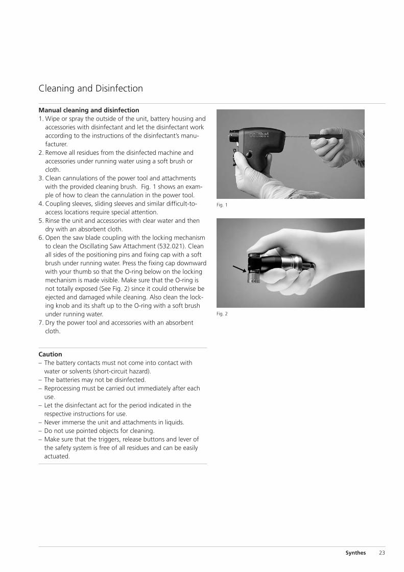
Manual cleaning and disinfection1. Wipe or spray the outside of the unit, battery housing and
accessories with disinfectant and let the disinfectant workaccording to the instructions of the disinfectant’s manu-facturer.
2. Remove all residues from the disinfected machine andaccessories under running water using a soft brush orcloth.
3. Clean cannulations of the power tool and attachmentswith the provided cleaning brush. Fig. 1 shows an exam-ple of how to clean the cannulation in the power tool.
4. Coupling sleeves, sliding sleeves and similar difficult-to-access locations require special attention.
5. Rinse the unit and accessories with clear water and thendry with an absorbent cloth.
6. Open the saw blade coupling with the locking mechanismto clean the Oscillating Saw Attachment (532.021). Cleanall sides of the positioning pins and fixing cap with a softbrush under running water. Press the fixing cap downwardwith your thumb so that the O-ring below on the lockingmechanism is made visible. Make sure that the O-ring isnot totally exposed (See Fig. 2) since it could otherwise beejected and damaged while cleaning. Also clean the lock-ing knob and its shaft up to the O-ring with a soft brushunder running water.
7. Dry the power tool and accessories with an absorbentcloth.
Caution– The battery contacts must not come into contact with
water or solvents (short-circuit hazard).– The batteries may not be disinfected. – Reprocessing must be carried out immediately after each
use.– Let the disinfectant act for the period indicated in the
respective instructions for use.– Never immerse the unit and attachments in liquids.– Do not use pointed objects for cleaning.– Make sure that the triggers, release buttons and lever of
the safety system is free of all residues and can be easilyactuated.
Cleaning and Disinfection
24 Synthes Colibri Instructions for Use
Care and Maintenance
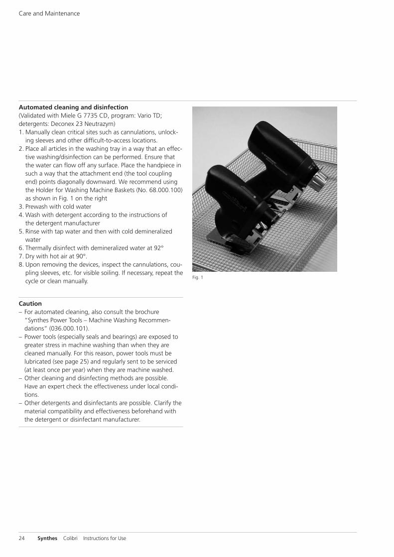
Automated cleaning and disinfection(Validated with Miele G 7735 CD, program: Vario TD;detergents: Deconex 23 Neutrazym)1. Manually clean critical sites such as cannulations, unlock-
ing sleeves and other difficult-to-access locations.2. Place all articles in the washing tray in a way that an effec-
tive washing/disinfection can be performed. Ensure thatthe water can flow off any surface. Place the handpiece insuch a way that the attachment end (the tool couplingend) points diagonally downward. We recommend usingthe Holder for Washing Machine Baskets (No. 68.000.100)as shown in Fig. 1 on the right
3. Prewash with cold water4. Wash with detergent according to the instructions of
the detergent manufacturer5. Rinse with tap water and then with cold demineralized
water6. Thermally disinfect with demineralized water at 92°7. Dry with hot air at 90°.8. Upon removing the devices, inspect the cannulations, cou-
pling sleeves, etc. for visible soiling. If necessary, repeat thecycle or clean manually.
Caution– For automated cleaning, also consult the brochure
“Synthes Power Tools – Machine Washing Recommen-dations” (036.000.101).
– Power tools (especially seals and bearings) are exposed togreater stress in machine washing than when they arecleaned manually. For this reason, power tools must belubricated (see page 25) and regularly sent to be serviced (at least once per year) when they are machine washed.
– Other cleaning and disinfecting methods are possible.Have an expert check the effectiveness under local condi-tions.
– Other detergents and disinfectants are possible. Clarify thematerial compatibility and effectiveness beforehand withthe detergent or disinfectant manufacturer.
Fig. 1
Synthes 25
2
2
2
2
2
2
2
2
2
Fig. 1
Fig. 3
Lubrication
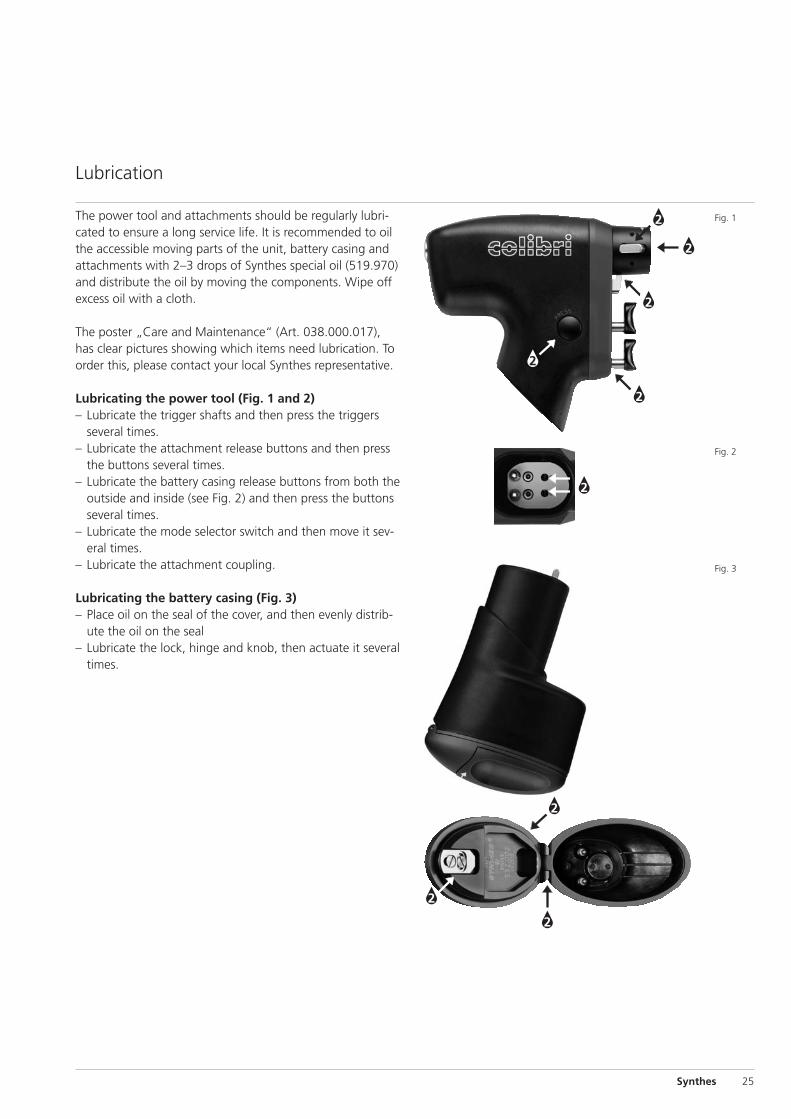
The power tool and attachments should be regularly lubri-cated to ensure a long service life. It is recommended to oilthe accessible moving parts of the unit, battery casing andattachments with 2–3 drops of Synthes special oil (519.970)and distribute the oil by moving the components. Wipe offexcess oil with a cloth.
The poster „Care and Maintenance“ (Art. 038.000.017), has clear pictures showing which items need lubrication. Toorder this, please contact your local Synthes representative.
Lubricating the power tool (Fig. 1 and 2)– Lubricate the trigger shafts and then press the triggers
several times.– Lubricate the attachment release buttons and then press
the buttons several times.– Lubricate the battery casing release buttons from both the
outside and inside (see Fig. 2) and then press the buttonsseveral times.
– Lubricate the mode selector switch and then move it sev-eral times.
– Lubricate the attachment coupling.
Lubricating the battery casing (Fig. 3)– Place oil on the seal of the cover, and then evenly distrib-
ute the oil on the seal– Lubricate the lock, hinge and knob, then actuate it several
times.
Fig. 2
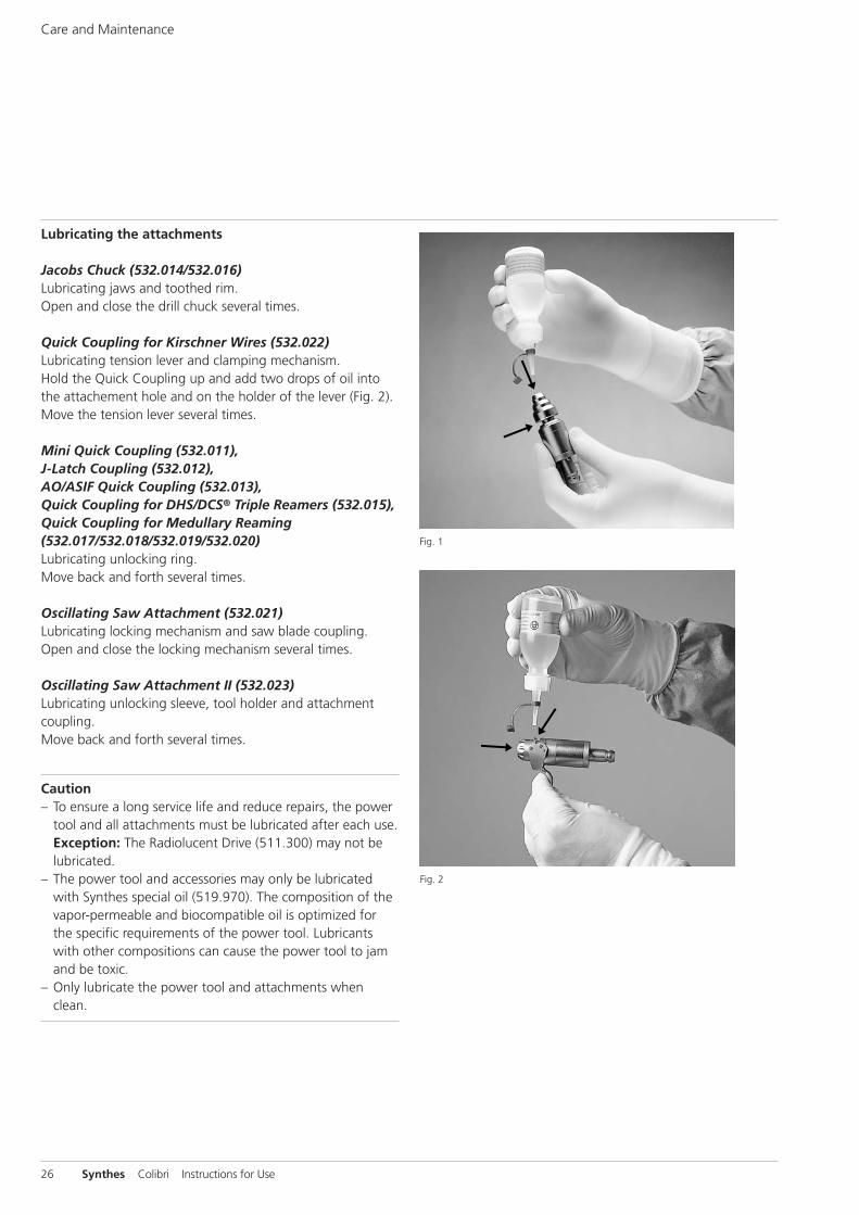
Fig. 2
Fig. 1
26 Synthes Colibri Instructions for Use
Lubricating the attachments
Jacobs Chuck (532.014/532.016)Lubricating jaws and toothed rim.Open and close the drill chuck several times.
Quick Coupling for Kirschner Wires (532.022) Lubricating tension lever and clamping mechanism.Hold the Quick Coupling up and add two drops of oil intothe attachement hole and on the holder of the lever (Fig. 2).Move the tension lever several times.
Mini Quick Coupling (532.011),J-Latch Coupling (532.012), AO/ASIF Quick Coupling (532.013), Quick Coupling for DHS/DCS® Triple Reamers (532.015), Quick Coupling for Medullary Reaming(532.017/532.018/532.019/532.020)Lubricating unlocking ring.Move back and forth several times.
Oscillating Saw Attachment (532.021)Lubricating locking mechanism and saw blade coupling.Open and close the locking mechanism several times.
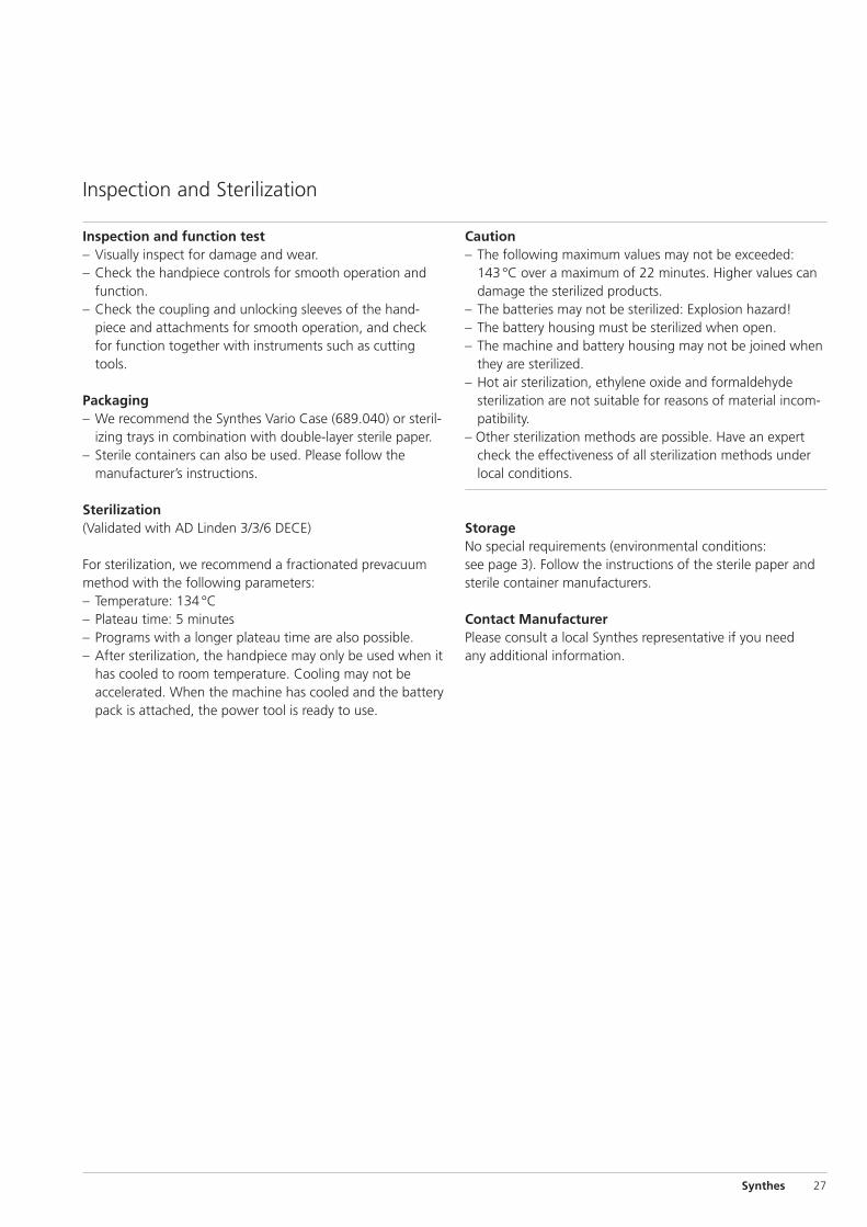
Oscillating Saw Attachment II (532.023)Lubricating unlocking sleeve, tool holder and attachmentcoupling.Move back and forth several times.
Caution– To ensure a long service life and reduce repairs, the power
tool and all attachments must be lubricated after each use.Exception: The Radiolucent Drive (511.300) may not belubricated.
– The power tool and accessories may only be lubricatedwith Synthes special oil (519.970). The composition of thevapor-permeable and biocompatible oil is optimized forthe specific requirements of the power tool. Lubricantswith other compositions can cause the power tool to jamand be toxic.
– Only lubricate the power tool and attachments whenclean.
Care and Maintenance
Synthes 27
Inspection and function test– Visually inspect for damage and wear.– Check the handpiece controls for smooth operation and
function.– Check the coupling and unlocking sleeves of the hand-
piece and attachments for smooth operation, and checkfor function together with instruments such as cuttingtools.
Packaging– We recommend the Synthes Vario Case (689.040) or steril-
izing trays in combination with double-layer sterile paper. – Sterile containers can also be used. Please follow the
manufacturer’s instructions.
Sterilization(Validated with AD Linden 3/3/6 DECE)
For sterilization, we recommend a fractionated prevacuummethod with the following parameters: – Temperature: 134 °C– Plateau time: 5 minutes– Programs with a longer plateau time are also possible. – After sterilization, the handpiece may only be used when it
has cooled to room temperature. Cooling may not beaccelerated. When the machine has cooled and the batterypack is attached, the power tool is ready to use.
Inspection and Sterilization
Caution– The following maximum values may not be exceeded:
143°C over a maximum of 22 minutes. Higher values candamage the sterilized products.
– The batteries may not be sterilized: Explosion hazard!– The battery housing must be sterilized when open.– The machine and battery housing may not be joined when
they are sterilized.– Hot air sterilization, ethylene oxide and formaldehyde
sterilization are not suitable for reasons of material incom-patibility.
– Other sterilization methods are possible. Have an expertcheck the effectiveness of all sterilization methods underlocal conditions.
StorageNo special requirements (environmental conditions: see page 3). Follow the instructions of the sterile paper andsterile container manufacturers.
Contact ManufacturerPlease consult a local Synthes representative if you need any additional information.
Charge the battery or replace it with a charged battery.
Let the tool cool to room temperature.
Turn the mode selector switch to ”ON“ or ”OSC“.
Reinsert the battery pack or replace it.
Charge the battery or replace it with a charged battery.
Let the tool cool to room temperature.
Charge the battery or replace it with a charged battery.
Lock the machine. Remove particleswith blunt tweezers.
Replace the attachment or tool, or send it to a Synthes service center.
Lock the machine. Remove the attach-ment, hold the drive shaft openingdown, and shake out the Kirschnerwire.
Replace the tool.
Tighten the locking knob of the sawblade coupling.
Turn the selector switch to “ON”.
Battery is dead.
The tool was not cooled off after sterilization.
Safety system is activated.
No contact between the tool and battery pack.
Battery is dead.
The tool is overheated (overload protection is activated).
Battery is dead.
The tool coupling is plugged fromdeposits
The attachment or tool is deformedfrom wear.
The Kirschner wire was inserted from the rear.
The cutting tool is blunt.
The saw blade locking mechanism is not tight.
The mode selector switch is set to “OSC”.
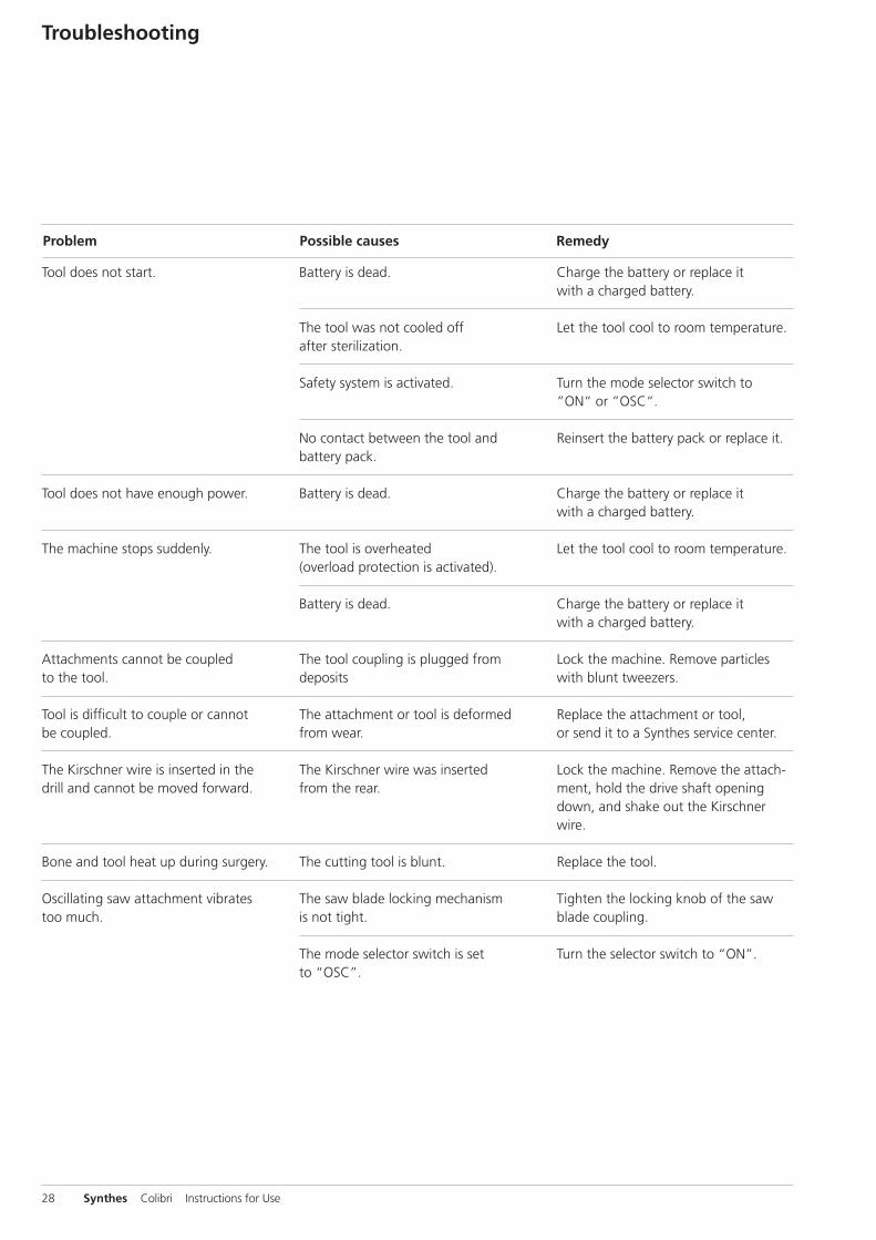
Problem Possible causes Remedy
Tool does not start.
Tool does not have enough power.
The machine stops suddenly.
Attachments cannot be coupled to the tool.
Tool is difficult to couple or cannot be coupled.
The Kirschner wire is inserted in thedrill and cannot be moved forward.
Bone and tool heat up during surgery.
Oscillating saw attachment vibrates too much.
28 Synthes Colibri Instructions for Use
Troubleshooting
Synthes 29
It is difficult to close the battery casing.
The battery casing knob is difficult to turn.
The triggers are difficult to move.
It is difficult to couple the batterycasing to the machine.
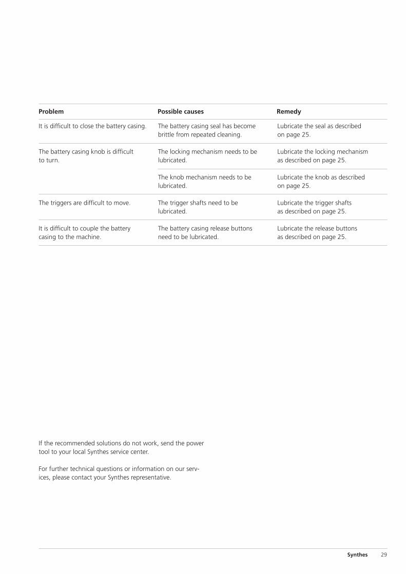
Problem Possible causes Remedy
The battery casing seal has becomebrittle from repeated cleaning.
The locking mechanism needs to belubricated.
The knob mechanism needs to belubricated.
The trigger shafts need to belubricated.
The battery casing release buttonsneed to be lubricated.
Lubricate the seal as described on page 25.
Lubricate the locking mechanism as described on page 25.
Lubricate the knob as described on page 25.
Lubricate the trigger shafts as described on page 25.
Lubricate the release buttons as described on page 25.
If the recommended solutions do not work, send the powertool to your local Synthes service center.
For further technical questions or information on our serv-ices, please contact your Synthes representative.

Saw blades (for 532.021)
Art. No. Art. No Usable Width Cut thicknessnon-sterile sterile length (mm) (mm) (mm)
532.041 532.041S 15 mm 6 mm 0.4 mm
532.042 532.042S 15 mm 10 mm 0.4 mm
532.043 532.043S 15 mm 16 mm 0.4 mm
532.044 532.044S 18 mm 4 mm 0.4 mm
532.045 532.045S 22 mm 8 mm 0.4 mm
532.046 532.046S 22 mm 12 mm 0.4 mm
532.047 532.047S 31 mm 6 mm 0.4 mm
532.048 532.048S 31 mm 10 mm 0.4 mm
532.061 532.061S 27 mm 6 mm 0.6 mm
532.062 532.062S 27 mm 10 mm 0.6 mm
532.063 532.063S 27 mm 14 mm 0.6 mm
532.064 532.064S 50 mm 10 mm 0.6 mm
532.065 532.065S 50 mm 14 mm 0.6 mm
532.066 532.066S 50 mm 20 mm 0.6 mm
532.067 532.067S 50 mm 27 mm 0.6 mm
Saw blades (for 532.023)
Art. No Usable Blade width Cut thickness Diametersterile length (mm) (mm) (mm) (mm)
03.000.311S 26.5 13.3 0.60 18
03.000.312S 25 16.3 0.60 22
03.000.313S 30 17.9 0.60 18
03.000.316S 30 21.9 0.60 22
Art. No Usable Blade width Cut thickness Shaft length sterile length(mm) (mm) (mm) (mm)
03.000.340S 7 12.0 0.38 70
03.000.341S 12 11.5 0.38 70
03.000.342S 12 9.5 0.38 70
03.000.343S 12 4.5 0.38 70
Cutting toolsDetailed ordering information on the cuttings tools for theColibri machine system with original-size pictures can befound in the brochure on saw blades (Art. No. 036.000.172).
Drive unit
532.001 Colibri
Charger, Battery and Accessories for Battery
532.002 Battery Casing for Nos. 532.001 and 532.010, Standard
532.003 Battery for Colibri, 12 V, Standard
532.032 Battery Casing for 14.4 V battery, for Colibri
532.033 Battery for Colibri, 14.4 V
532.004 Sterile Cover for Colibri
530.600 Universal Battery Charger for Synthes® Batteries, 2 Charging Bays
530.601 Universal Battery Charger for Synthes® Batteries, 4 Charging Bays
Attachments
532.011 Mini Quick Coupling, for Colibri
532.012 J-Latch Coupling for Colibri
532.013 AO/ASIF Quick Coupling for Colibri
532.014 Jacobs Chuck with Key, for Colibri, clamping range up to � 6.0 mm
532.016 Jacobs Chuck with Key, for Colibri, clamping range up to � 4.0 mm
532.015 Quick Coupling for DHS/DCS triple reamers, for Colibri *
532.017 AO/ASIF Quick Coupling for Medullary Reaming, for Colibri*
532.018 HUDSON Quick Coupling for Medullary Reaming, for Colibri*
532.019 Trinkle Quick Coupling for Medullary Reaming, for Colibri*
532.020 Trinkle Quick Coupling, modified, for Medullary Reaming, for Colibri*
532.021 Oscillating Saw Attachment, for Colibri
532.022 Quick Coupling for Kirschner Wires � 0.6 to 3.2 mm, for Colibri
532.023 Oscillating Saw Attachment II (Crescentic Technique), for Colibri
532.031 Adapter for Radiolucent Drive, for Colibri
511.300 Radiolucent Drive
511.773 Torque Limiter, 1.5 Nm, for AO/ASIF Quick Coupling
511.776 Torque Limiter, 0.8 Nm, for AO/ASIF Quick Coupling
511.777 Torque Limiter, 0.4 Nm, for AO/ASIF Quick Coupling
Power supply, power adapter and accessories
05.001.002 Basic Console, for Electric Pen Drive
05.001.024 Adapter for Colibri, for Electric Pen Drive
05.001.027 Seal Nipple for Cable, for Electric Pen Drive
Accessories
689.040 Vario Case™, size 1/1, for Colibri, without lid, without Contents
689.042 Vario Case, size 1/2, for Colibri Power Pack, without lid,without contents
689.507 Lid (stainless steel), size 1/1, for Vario Case
689.537 Lid (stainless steel), size 1/2, for Vario Case
519.400 Cleaning Brush
519.970 Oil Dispenser with Synthes Special Oil
532.024 Cleaning Brush for Oscillating Saw Attachment II (532.023)
30 Synthes Colibri Instructions for Use
Ordering Information
* It is recommendable to use the more powerful battery for these attachments(532.033)


036.
000.
173
SE_0
6600
5 A
A40
0500
22©
Syn
thes
2006
Subj
ect
to m
odifi
catio
ns
Presented by: