concept description: meerkat receptor for consideration by … · 2012-09-25 · meerkat receptor...
TRANSCRIPT
MeerKAT Receptor for consideration by SKA WP2-020.045.010-TD-005 Commercial in Confidence Revision: A
June 2011 Page 1 of 74
Name Designation Affiliation Date Signature
Willem Esterhuyse MeerKAT Project Manager SKA SA (NRF) June 2011
Additional Authors
Thomas Kusel MeerKAT System Engineer SKA SA (NRF) June 2011
Isak Theron EM Specialist EMSS June 2011
Philip la Grange Receiver System Engineer EMSS June 2011
Francois Kapp DBE Subsystem Manager SKA SA (NRF) June 2011
Hendrik Bester Mechanical Specialist SKA SA (NRF) June 2011
Justin Jonas Associate Director SKA SA (NRF) June 2011
Submitted by:
Anita Loots Associate Director SKA SA (NRF) June 2011
Accepted by:
Approved by:
CONCEPT DESCRIPTION: MEERKAT RECEPTOR FOR
CONSIDERATION BY SKA
Document number .................................................................. WP2-020.045.010-TD-005
Revision ........................................................................................................................... A
Author ................................................................................................. Willem Esterhuyse
Date ................................................................................................................... June 2011
Status ................................................................................................................. Approved

MeerKAT Receptor for consideration by SKA WP2-020.045.010-TD-005 Commercial in Confidence Revision: A
June 2011 Page 2 of 74
DOCUMENT HISTORY
Revision Date Of Issue Engineering Change
Number
Comments
A June 2011 N/A SKA SA Internally approved version
B - -
C - -
DOCUMENT SOFTWARE
Package Version Filename
Wordprocessor MsWord Word 2007 WP2-020_045_010-TD-005A_MKReceptor2
Block diagrams
Other
SKA ORGANISATION DETAILS
Name SKA Program Development Office
Physical/Postal
Address
Jodrell Bank Centre for Astrophysics
Alan Turing Building
The University of Manchester
Oxford Road
Manchester, UK
M13 9PL
Fax. +44 (0)161 275 4049
Website www.skatelescope.org
SKA SA ORGANISATION DETAILS
Name SKA-SA
Physical/Postal
Address The Park, 3rd Floor SKA-SA
Park Rd PO Box 522940
Pinelands Saxonwold
7405 2132
Tel. +27 21 506 7300
Fax. +27 21 506 7375
Website www.ska.ac.za

MeerKAT Receptor for consideration by SKA WP2-020.045.010-TD-005 Commercial in Confidence Revision: A
June 2011 Page 3 of 74
TABLE OF CONTENTS
1 INTRODUCTION ............................................................................................................ 10
1.1 Purpose of the document ..................................................................................................... 11
2 REFERENCES ................................................................................................................ 12
3 CONTEXT .................................................................................................................... 13
3.1 SKA Hierarchy ........................................................................................................................ 13
3.2 Role of Receptor in the Dish Array ........................................................................................ 14
3.3 Context diagram .................................................................................................................... 15
4 MEERKAT PHYSICAL DESCRIPTION ................................................................................... 15
4.1 Dish ....................................................................................................................................... 17
4.1.1 Functional overview ...................................................................................................... 17
4.1.2 Geometry ...................................................................................................................... 17
4.1.3 Dish concept description ............................................................................................... 18
4.2 Receiver ................................................................................................................................. 21
4.3 Digitizer ................................................................................................................................. 24
5 REQUIREMENTS ........................................................................................................... 25
5.1 Functional Requirements ...................................................................................................... 25
5.2 Non-Functional Requirements .............................................................................................. 34
5.2.1 Manufacturing concept ................................................................................................. 34
5.2.2 Support concept ............................................................................................................ 35
5.2.3 Reliability ....................................................................................................................... 35
5.2.4 Operating cost ............................................................................................................... 35
6 TECHNICAL PROGRESS TO DATE ........................................................................................ 36
6.1 Dish ....................................................................................................................................... 37
6.1.1 XDM and KAT7 areas of key learning ............................................................................ 39
6.1.1.1 FEA Analyses of Antenna Structures (Dishes) ........................................................... 39
6.1.1.1.1 Loadcases ............................................................................................................ 39
6.1.1.1.2 FEA Results .......................................................................................................... 40
6.1.1.2 Composite Reflectors – “design for manufacture” ................................................... 42
6.1.1.2.1 Thermal performance ......................................................................................... 42
6.1.1.2.2 Obtaining a reflective surface for radio astronomy ............................................ 44
6.1.1.2.3 Process ................................................................................................................ 45
6.1.1.2.4 Layup of the laminates ........................................................................................ 46
6.1.1.2.5 On-site manufacture of composite reflectors .................................................... 47
6.1.1.2.6 Composite reflector tolerance build-up and mould options .............................. 47

MeerKAT Receptor for consideration by SKA WP2-020.045.010-TD-005 Commercial in Confidence Revision: A
June 2011 Page 4 of 74
6.1.1.2.7 Composite reflector transport post-manufacture .............................................. 49
6.1.1.3 Cable routing principles in order to minimize EMI ................................................... 50
6.1.1.4 Lightning protection .................................................................................................. 51
6.1.1.5 Antenna Drives .......................................................................................................... 51
6.1.1.6 Thermal Management .............................................................................................. 53
6.1.2 Concept study towards MeerKAT ................................................................................. 53
6.1.2.1 Offset Gregorian vs. Prime Focus dishes................................................................... 53
6.1.2.2 Reflector Shaping ...................................................................................................... 54
6.1.2.3 Feed-low vs. Feed-high (Offset dishes) ..................................................................... 55
6.1.2.3.1 Performance ....................................................................................................... 55
6.1.2.3.2 Practicality........................................................................................................... 58
6.1.2.3.3 Feed-low vs. Feed-high verdict ........................................................................... 58
6.1.2.4 Stow position for offset dishes ................................................................................. 59
6.1.2.5 Feed Indexer ............................................................................................................. 61
6.1.3 Work in Progress for MeerKAT ..................................................................................... 62
6.1.3.1 Composite Material Qualification ............................................................................. 62
6.1.3.1.1 Geometrical stability of the reflective surface ................................................... 63
6.1.3.1.2 Mechanical integrity of the reflective surface .................................................... 63
6.1.3.1.3 Resin/paint system dielectric loss factor ............................................................ 63
6.1.3.1.4 Resin film thickness in front of mesh .................................................................. 64
6.1.3.2 MeerKAT Concept Analyses ...................................................................................... 66
6.1.3.3 Optics optimization ................................................................................................... 66
6.2 Receiver ................................................................................................................................. 67
6.2.1 KAT7 performance ........................................................................................................ 67
6.2.1.1 Feed horn and OMT .................................................................................................. 67
6.2.1.2 System temperature ................................................................................................. 69
6.2.2 KAT7 areas of key learning ............................................................................................ 69
6.2.2.1 Cryo-cooling .............................................................................................................. 69
6.2.3 Concept study towards MeerKAT ................................................................................. 70
6.2.3.1 Comparison between wideband (4:1) and octave band receivers ........................... 70
6.2.3.2 Cryo-cooling .............................................................................................................. 70
6.2.3.3 Expected system temperature .................................................................................. 71
6.3 Digitizer ................................................................................................................................. 72
7 COST ESTIMATES .......................................................................................................... 73
8 PLANS FOR FURTHER DEVELOPMENT ................................................................................. 74

MeerKAT Receptor for consideration by SKA WP2-020.045.010-TD-005 Commercial in Confidence Revision: A
June 2011 Page 5 of 74
LIST OF FIGURES
FIGURE 1 MEERKAT RECEPTOR DEFINING HIGH-LEVEL TERMINOLOGY ........................................... 11
FIGURE 2 SKA DISH ARRAY HIERARCHY ................................................................................ 13
FIGURE 3 MEERKAT RECEPTOR HIERARCHY .......................................................................... 14
FIGURE 4 MEERKAT RECEPTOR CONTEXT DIAGRAM ................................................................ 15
FIGURE 5 BLOCK DIAGRAM OF THE MEERKAT RECEPTOR .......................................................... 16
FIGURE 6 GEOMETRY OF MEERKAT REFLECTOR ...................................................................... 17
FIGURE 7 DISH LAYOUT .................................................................................................... 18
FIGURE 8 YOKE AND TRUNNION SHAFT ................................................................................. 19
FIGURE 9 PEDESTAL AND AZIMUTH BEARING .......................................................................... 19
FIGURE 10 CONNECTING BEAM AND FEED INDEXER ................................................................ 20
FIGURE 11 PROPOSED MEERKAT DISH WITH KAROO BACKGROUND ........................................... 20
FIGURE 12 SIMPLIFIED BLOCK DIAGRAM OF THE RECEIVER ........................................................ 22
FIGURE 13 MEERKAT L-BAND OMT ................................................................................. 23
FIGURE 14 MEERKAT L-BAND HORN ................................................................................. 23
FIGURE 15 KAT7 COMPONENTS TRANSPORTED TO SITE .......................................................... 34
FIGURE 16 UPGRADED SITE COMPLEX INFRASTRUCTURE FOR MEERKAT ...................................... 34
FIGURE 17 OVERVIEW OF THE MEERKAT PROJECT PROGRESS .................................................. 36
FIGURE 18 15M XDM TELESCOPE AT HARTRAO .................................................................. 38
FIGURE 19 12M KAT7 TELESCOPE AND ARRAY AT KAROO SITE ................................................. 38
FIGURE 20 TEMPERATURE MEASUREMENTS ON BACK OF REFLECTOR ........................................... 39
FIGURE 21 TYPICAL FEM RESULT (MEERKAT) ...................................................................... 41
FIGURE 22 TYPICAL REFLECTOR SURFACE DEFORMATION (RELATIVE TO BEST FIT PARABOLA) ............... 41
FIGURE 23 USE OF ALUMINIUM ARC SPRAYING ON XDM ......................................................... 44
FIGURE 24 TESTING TRANSFER ON LAYUP USING MESH AS REFLECTIVE LAYER ................................. 45
FIGURE 25 SCHEMATIC OF INFUSION PROCESS AND REFLECTOR BEING MOULDED ............................ 45
FIGURE 26 AN ILLUSTRATION OF SYMMETRIC AND BALANCED LAMINATE LAYUPS ............................ 46
FIGURE 27 EXAMPLE OF BALANCED AND SYMMETRIC LAYUP ...................................................... 46
FIGURE 28 KAT7 REFLECTOR AND BACKING STRUCTURE TAKEN OF MOULD AT KAROO SITE ................ 47

MeerKAT Receptor for consideration by SKA WP2-020.045.010-TD-005 Commercial in Confidence Revision: A
June 2011 Page 6 of 74
FIGURE 29 KAT7 DISH BEING TRANSPORTED ........................................................................ 49
FIGURE 30 CABLES ROUTED AGAINST METAL SURFACES INSIDE THE KAT7 PEDESTAL ........................ 50
FIGURE 31 CABLES JOINING CABINET ON ONE SIDE ONLY .......................................................... 51
FIGURE 32 SINGLE AZIMUTH DRIVE CONCEPT ........................................................................ 52
FIGURE 33 ELEVATION LEAD SCREW ................................................................................... 52
FIGURE 34 FEED-LOW VS. FEED-HIGH COMPARISON (COURTESY MATT FLEMING) ........................... 55
FIGURE 35 SYMMETRY PLANE FAR FIELD PATTERN OF AN OFFSET GREGORIAN REFLECTOR .................. 57
FIGURE 36 OFFSET GREGORIAN WITH SMALL EXTENSION AT BOTTOM OF SUB-REFLECTOR ................. 57
FIGURE 37 SPILL-OVER TIPPING CURVES FOR THE DIFFERENT FEED CONFIGURATIONS ........................ 58
FIGURE 38 APPROXIMATE STOW POSITION FOR THE MEERKAT RECEPTOR ................................... 59
FIGURE 39 L-BAND (1 – 1.75GHZ) RECEIVER ENVELOPE ......................................................... 61
FIGURE 40 UHF-BAND (0.58 – 1.015GHZ) RECEIVER ENVELOPE .............................................. 61
FIGURE 41 X-BAND (8 – 14.5GHZ) RECEIVER ENVELOPE ......................................................... 61
FIGURE 42 SCHEMATIC DIAGRAM OF FEED INDEXER ................................................................ 62
FIGURE 43 RADIO QUALITY TEST AT HARTRAO ..................................................................... 64
FIGURE 44 SEQUENCE OF EVENTS FOR THE QUALIFICATION ACTIVITIES .......................................... 65
FIGURE 45 KAT7 RECEIVER ............................................................................................. 67
FIGURE 46 PREDICTED AND MEASURED FEED PATTERN OF THE KAT7 FEED AT 1.4GHZ .................... 68
FIGURE 47 KAT7 OMT .................................................................................................. 68
FIGURE 48 KAT7 RECEIVER ............................................................................................. 69
FIGURE 49 KAT7 CRYOSTAT ASSEMBLY BACK PLATE ............................................................... 70
FIGURE 50 DIGITIZER BLOCK DIAGRAM ............................................................................... 72
FIGURE 51 OVERVIEW OF FURTHER DEVELOPMENT PHASE ........................................................ 74

MeerKAT Receptor for consideration by SKA WP2-020.045.010-TD-005 Commercial in Confidence Revision: A
June 2011 Page 7 of 74
LIST OF TABLES
TABLE 1 MEERKAT KEY SPECS .......................................................................................... 10
TABLE 2 COMPLIANCE MATRIX ......................................................................................... 33
TABLE 3 LOAD CASES FOR ANALYSING DISHES ....................................................................... 40
TABLE 4 MATERIAL PROPERTY COMPARISON ......................................................................... 42
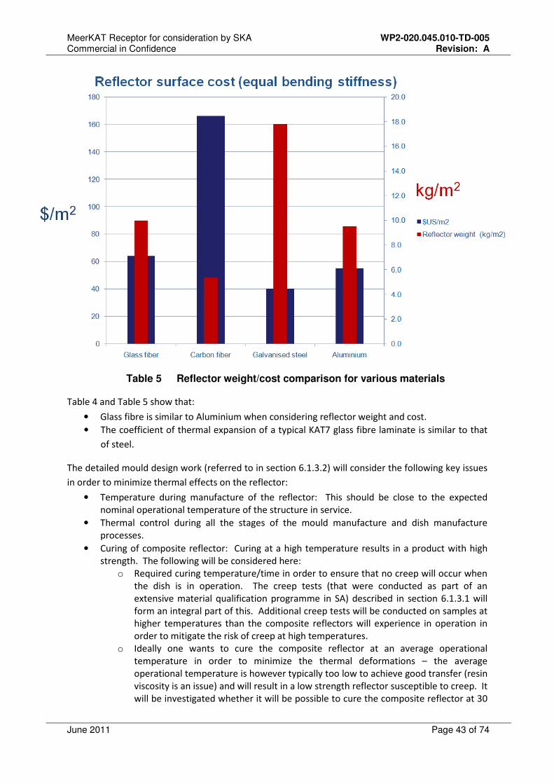
TABLE 5 REFLECTOR WEIGHT/COST COMPARISON FOR VARIOUS MATERIALS .................................. 43
TABLE 6 REFLECTOR TOLERANCE BUILD-UP ........................................................................... 48
TABLE 7 ESTIMATED SYSTEM NOISE EXCLUDING LNA FOR OFFSET GREGORIAN ............................... 71
MeerKAT Receptor for consideration by SKA WP2-020.045.010-TD-005 Commercial in Confidence Revision: A
June 2011 Page 8 of 74
LIST OF ABBREVIATIONS
AC ................................. Alternating Current
Ae or Aeff ........................ Effective Area
ACU ............................... Antenna Control Unit
ADC ............................... Analogue Digital Converter
ASTM ............................ American Society for Testing and Materials
BW ................................. Bandwidth
C .................................... Celsius
C&M .............................. Control and Monitoring
CASPER........................ Centre for Astronomy Signal Processing and Electronics Research
CFD ............................... Computational Fluid Dynamics
CoDR ............................. Conceptual Design Review
CSIR .............................. Council for Scientific and Industrial Research
DRM .............................. Design Reference Mission
EEPRM .......................... Electrically Erasable Programmable Read-only Memory
EM ................................. Electromagnetic
EMI ................................ Electromagnetic Interference
EMSS ............................ Electromagnetic Software and Systems (PTY) Ltd
EoR ............................... Epoch of Re-ionisation
FEA ............................... Finite Element Analyses
FEM ............................... Finite Element Modelling
FLOPS ........................... Floating Point Operations per second
FoV ................................ Field of View
FPGA ............................. Field-programmable Gate Array
GbE ............................... Gigabit Ethernet
GHz ............................... Gigahertz
GM ................................. Gifford-McMahon
HPBW ............................ Half power beam width
IEEE .............................. Institute of Electrical and Electronic Engineers
K .................................... Kelvin
KAT ............................... Karoo Array Telescope
KAT7 ............................. Karoo Array Telescope 7 dish array
KAPB ............................. Karoo Array Processor Building
KATCP .......................... KAT Control Protocol
l/s ................................... liter/second
LEMP ............................. Logistic Engineering Management Plan
LNA ............................... Low Noise Amplifier
LRU ............................... Line Replaceable Unit

MeerKAT Receptor for consideration by SKA WP2-020.045.010-TD-005 Commercial in Confidence Revision: A
June 2011 Page 9 of 74
LRUs ............................. Line Replaceable Units
m ................................... meter
mbar .............................. millibar
MIL-STD ........................ military standard
MMS .............................. Mechanics Materials and Structures (PTY) Ltd
MTBF ............................. Mean Time Between Failure
Ny .................................. Nyquist
OG ................................. Offset Gregorian
OMT .............................. Ortho-Mode Transducer
OTPF ............................. Observing Time Performance Factor
PAF ............................... Phased Array Feed
PDR ............................... Preliminary Design Review
PEP ............................... Project Execution Plan
PrepSKA........................ Preparatory Phase for the SKA
QFP ............................... Quad Flat Package
RF ................................. Radio Frequency
RFI ................................. Radio Frequency Interference
RMS .............................. root mean square
SE .................................. System Engineering
SEMP ............................ System Engineering Management Plan
SERDES........................ Serializer/Deserializer
SFP+ ............................. small form-factor pluggable
SKA ............................... Square Kilometre Array
SKADS .......................... SKA Design Studies
SPDO ............................ SKA Program Development Office
SPEAD .......................... Signal Processing Environment for Algorithm Development
SSFoM .......................... Survey Speed Figure of Merit
TBC ............................... To be Confirmed
TBD ............................... To be Determined
TFR ............................... Timing Frequency Reference
Tsys ................................. System noise temperature
UHF ............................... Ultra High Frequency
UHF-band ...................... 0.58 – 1.015GHz
UPS ............................... Uninterruptible Power Supply
US ................................. United States
UV ................................. Ultraviolet
XDM .............................. Experimental Development Model

MeerKAT Receptor for consideration by SKA WP2-020.045.010-TD-005 Commercial in Confidence Revision: A
June 2011 Page 10 of 74
1 Introduction
The MeerKAT array, currently taking shape in South Africa’s Karoo radio astronomy reserve, has
been designated a precursor for the SKA mid-frequency dish array, and will be a world-class radio
telescope capable of transformational science. It will be the largest and most sensitive radio
telescope array in the southern hemisphere until it is surpassed by the SKA. In the context of this
document the MeerKAT receptor comprising the dish, receivers and digitizer, provides a complete,
end-to-end SKA-mid receptor concept.
The MeerKAT array will consist of 64 dishes of 13.5 m projected diameter each with an offset
Gregorian configuration, giving it a sensitivity of approximately 300 m2/K in the L-band. An offset
optical configuration has been chosen because its unblocked aperture provides uncompromised
optical performance and sensitivity, excellent imaging quality, and good rejection of unwanted radio
frequency interference from satellites and terrestrial transmitters. It also enables the installation of
multiple receiver systems in the primary and secondary focal areas, and provides a number of
operational advantages.
Number of antennas 64 offset Gregorian
Projected dish diameter 13.5 m
Minimum baseline 29 m
Maximum baseline 8 km (extending to 20 km later)
Frequency bands (receivers) 0.58 – 1.015 GHz
1 – 1.75 GHz
8 – 14.5 GHz
Continuum imaging dynamic range at 1.4 GHz 60 dB
Line-to-line dynamic range at 1.4 GHz 40 dB
Mosaicing imaging dynamic range at 14 GHz 27 dB
Linear polarisation cross coupling across -3 dB beam -30 dB
Sensitivity (0.58 – 1.015GHz) 220 m2/K required
Sensitivity (1 – 1.75GHz) 220 m2/K required
(300 m2/K achievable)
Sensitivity (8 – 14.5GHz) 200 m2/K required
Table 1 MeerKAT key Specs
Table 1 lists the key high-level MeerKAT specifications. The MeerKAT will have three high sensitivity
single-pixel receivers, each covering a 1:1.75 frequency range (i.e. almost an octave). Provision will
be made for a 4th receiver, but the concept details (for feed indexer) have not been finalized
(current concept described in section 6.1.2.5). It would be possible to develop a feed indexer
concept that will meet the SKA requirements. Whilst Figure 1 shows a rotator type indexer, a linear
slider, fan type and other indexer concepts will be considered in the final design phases of MeerKAT.
A Logistic Engineering Management Plan has been prepared for MeerKAT [12]. It is based on the
KAT71 Logistic Engineering Management Plan [13], which is being implemented at the moment -
details of the implementation can be provided on request.
1KAT7 is a 7-dish engineering prototype array designed and built as part of the risk-driven system engineering approach to
deliver MeerKAT.
MeerKAT Receptor for consideration by SKA WP2-020.045.010-TD-005 Commercial in Confidence Revision: A
June 2011 Page 11 of 74
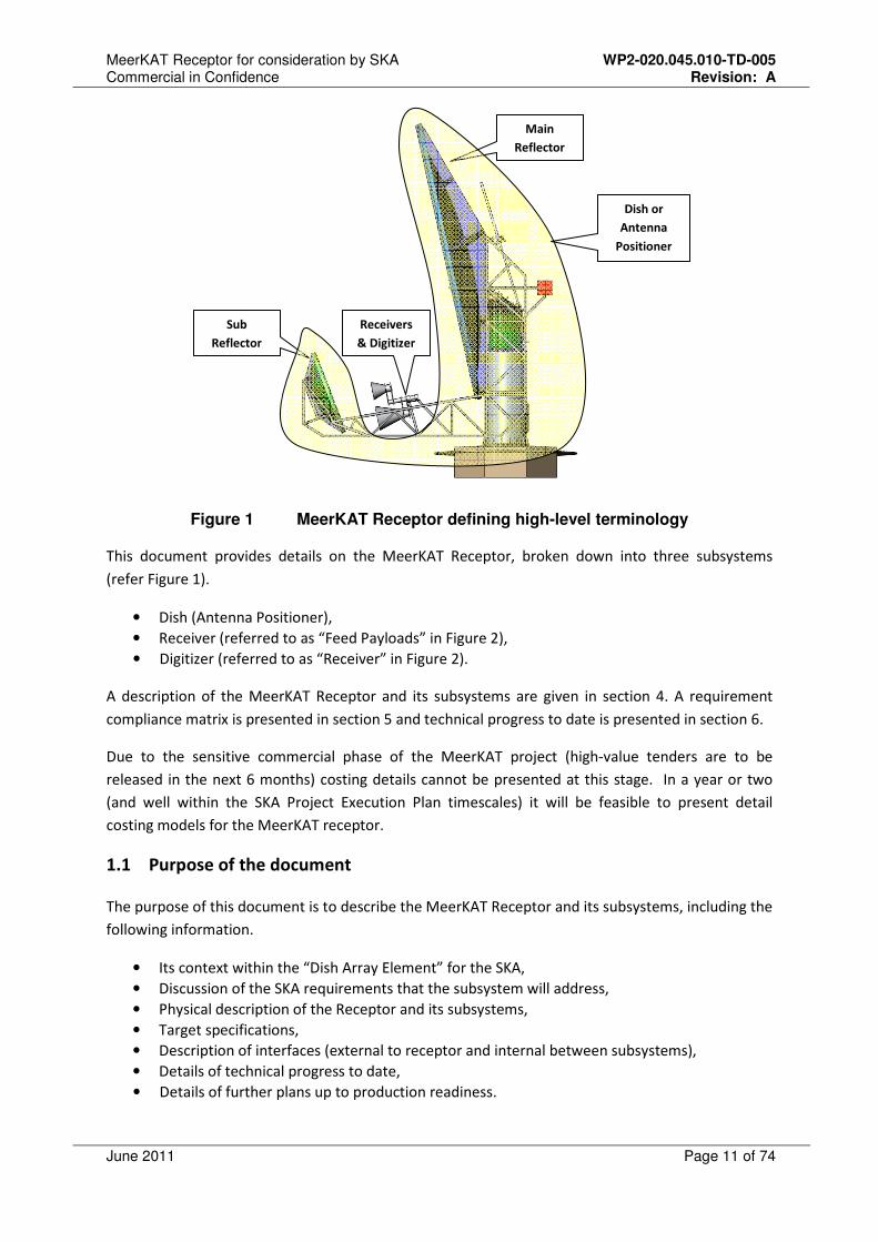
Figure 1 MeerKAT Receptor defining high-level terminology
This document provides details on the MeerKAT Receptor, broken down into three subsystems
(refer Figure 1).
• Dish (Antenna Positioner),
• Receiver (referred to as “Feed Payloads” in Figure 2),
• Digitizer (referred to as “Receiver” in Figure 2).
A description of the MeerKAT Receptor and its subsystems are given in section 4. A requirement
compliance matrix is presented in section 5 and technical progress to date is presented in section 6.
Due to the sensitive commercial phase of the MeerKAT project (high-value tenders are to be
released in the next 6 months) costing details cannot be presented at this stage. In a year or two
(and well within the SKA Project Execution Plan timescales) it will be feasible to present detail
costing models for the MeerKAT receptor.
1.1 Purpose of the document
The purpose of this document is to describe the MeerKAT Receptor and its subsystems, including the
following information.
• Its context within the “Dish Array Element” for the SKA,
• Discussion of the SKA requirements that the subsystem will address,
• Physical description of the Receptor and its subsystems,
• Target specifications,
• Description of interfaces (external to receptor and internal between subsystems),
• Details of technical progress to date,
• Details of further plans up to production readiness.
Main
Reflector
Sub
Reflector
Receivers
& Digitizer
Dish or
Antenna
Positioner

MeerKAT Receptor for consideration by SKA WP2-020.045.010-TD-005 Commercial in Confidence Revision: A
June 2011 Page 12 of 74
2 References
It should be noted that all documents that are listed in this section are not freely available in the
public domain. Interested parties are advised to get in touch with SKA SA regarding the content of
these.
[1] Requirements document for SKA Dish Array, SPDO doc. no. WP2-020.030.020-RS-001 Rev A
[2] MKAT-00002-219, August 2010, MeerKAT offset antenna concept study report
[3] MKAT-00010-34, January 2011, Error budget report for MeerKAT offset concept
[4] 3346-2908-23, July 2010, MeerKAT Gregorian offset antenna structure concept design and
analysis
[5] MKAT-00004-219, June 2010, KAT offset Gregorian 12m elevation servo calculations
[6] MKAT-00004-219, June 2010, KAT offset Gregorian 12m azimuth servo
[7] December 2007, Review and Design of a Lightning Protection System for XDM and KAT-7 Dishes
[8] EMSS Antennas Document EA-MK-WP-0005, MeerKAT Cooling and Vacuum concepts: KAT-7
Cooling and Vacuum performance in operation
[9] EMSS Antennas Document EA-MK-WP-0012, MeerKAT Cooling Architecture Selection Study
[10] EMSS Antennas Document EA-K7-237-PTAS-02, May 2010, KAT-7: Receiver Temperature
Measurement and Noise Injection Calibration
[11] M0000-0000V1-03 DD Rev 1, June 2010, MeerKAT Concept Options and tradeoffs
[12] M2000-0000V1-02 Rev 1, May 2010, MeerKAT Logistic Engineering Management Plan (LEMP)
[13] NRF-KAT-7-9.0-MP/001 Rev 1, KAT-7 Telescope Logistic Engineering Management Plan (LEMP)
MeerKAT Receptor for consideration by SKA WP2-020.045.010-TD-005 Commercial in Confidence Revision: A
June 2011 Page 13 of 74
3 Context
3.1 SKA Hierarchy
The SKA Systems Engineering Management plan has defined multiple layers of hierarchy:
L7: SKA User
L6: System
L5: Element
L4: Sub-System
L3: Assembly
L2: Component
L1: Part
Although not explicitly stated in the SEMP, the hierarchical approach has the advantage of breaking
down the complexity of the system. Each layer is only concerned about its own functionality and its
interface to the immediately adjacent layers.
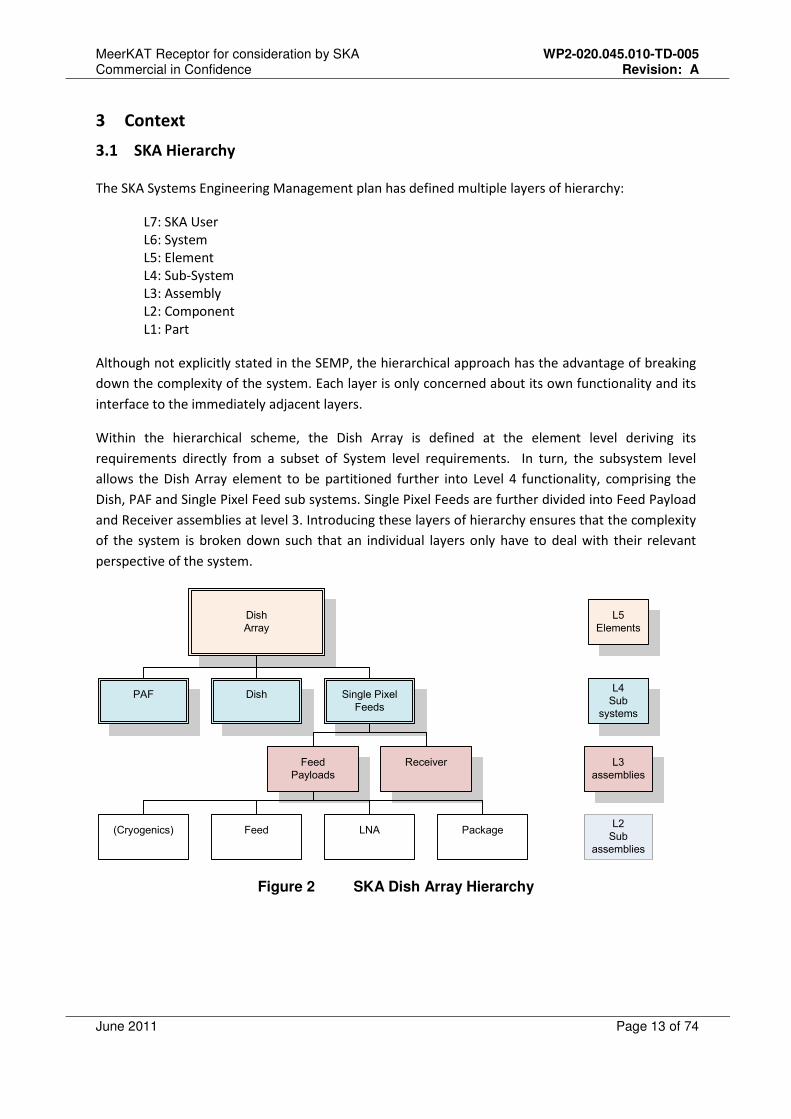
Within the hierarchical scheme, the Dish Array is defined at the element level deriving its
requirements directly from a subset of System level requirements. In turn, the subsystem level
allows the Dish Array element to be partitioned further into Level 4 functionality, comprising the
Dish, PAF and Single Pixel Feed sub systems. Single Pixel Feeds are further divided into Feed Payload
and Receiver assemblies at level 3. Introducing these layers of hierarchy ensures that the complexity
of the system is broken down such that an individual layers only have to deal with their relevant
perspective of the system.
Dish
Array
DishPAF Single Pixel
Feeds
Feed
Payloads
Receiver
Feed LNA(Cryogenics)
L5
Elements
L4
Sub
systems
L3
assemblies
L2
Sub
assemblies
Package
Figure 2 SKA Dish Array Hierarchy
MeerKAT Receptor for consideration by SKA WP2-020.045.010-TD-005 Commercial in Confidence Revision: A
June 2011 Page 14 of 74
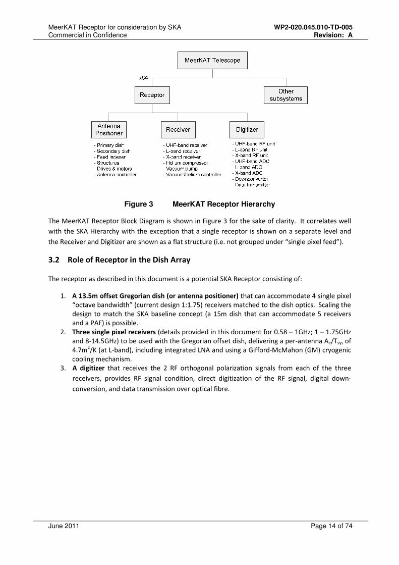
Figure 3 MeerKAT Receptor Hierarchy
The MeerKAT Receptor Block Diagram is shown in Figure 3 for the sake of clarity. It correlates well
with the SKA Hierarchy with the exception that a single receptor is shown on a separate level and
the Receiver and Digitizer are shown as a flat structure (i.e. not grouped under “single pixel feed”).
3.2 Role of Receptor in the Dish Array
The receptor as described in this document is a potential SKA Receptor consisting of:
1. A 13.5m offset Gregorian dish (or antenna positioner) that can accommodate 4 single pixel
“octave bandwidth” (current design 1:1.75) receivers matched to the dish optics. Scaling the
design to match the SKA baseline concept (a 15m dish that can accommodate 5 receivers
and a PAF) is possible.
2. Three single pixel receivers (details provided in this document for 0.58 – 1GHz; 1 – 1.75GHz
and 8-14.5GHz) to be used with the Gregorian offset dish, delivering a per-antenna Ae/Tsys of
4.7m2/K (at L-band), including integrated LNA and using a Gifford-McMahon (GM) cryogenic
cooling mechanism.
3. A digitizer that receives the 2 RF orthogonal polarization signals from each of the three
receivers, provides RF signal condition, direct digitization of the RF signal, digital down-
conversion, and data transmission over optical fibre.
MeerKAT Receptor for consideration by SKA WP2-020.045.010-TD-005 Commercial in Confidence Revision: A
June 2011 Page 15 of 74
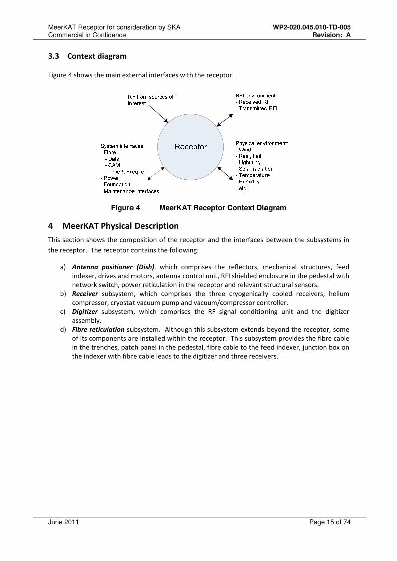
3.3 Context diagram
Figure 4 shows the main external interfaces with the receptor.
Figure 4 MeerKAT Receptor Context Diagram
4 MeerKAT Physical Description
This section shows the composition of the receptor and the interfaces between the subsystems in
the receptor. The receptor contains the following:
a) Antenna positioner (Dish), which comprises the reflectors, mechanical structures, feed
indexer, drives and motors, antenna control unit, RFI shielded enclosure in the pedestal with
network switch, power reticulation in the receptor and relevant structural sensors.
b) Receiver subsystem, which comprises the three cryogenically cooled receivers, helium
compressor, cryostat vacuum pump and vacuum/compressor controller.
c) Digitizer subsystem, which comprises the RF signal conditioning unit and the digitizer
assembly.
d) Fibre reticulation subsystem. Although this subsystem extends beyond the receptor, some
of its components are installed within the receptor. This subsystem provides the fibre cable
in the trenches, patch panel in the pedestal, fibre cable to the feed indexer, junction box on
the indexer with fibre cable leads to the digitizer and three receivers.
MeerKAT Receptor for consideration by SKA WP2-020.045.010-TD-005 Commercial in Confidence Revision: A
June 2011 Page 16 of 74
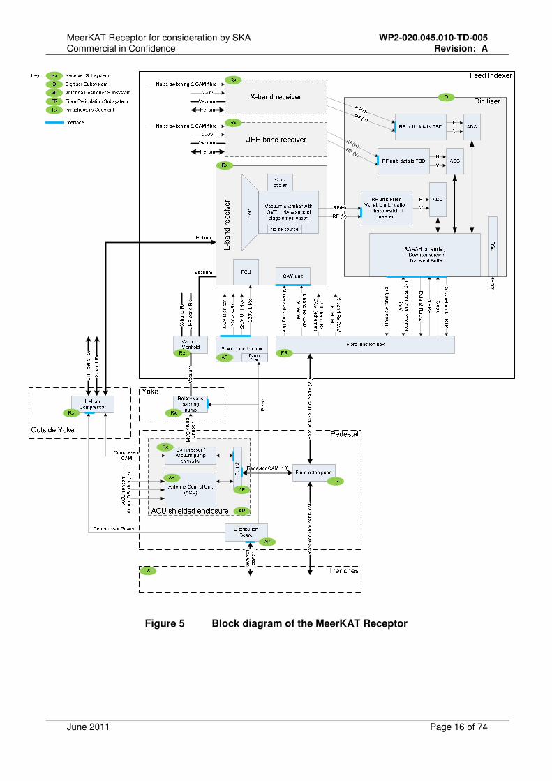
RF(H)RF (V)
Figure 5 Block diagram of the MeerKAT Receptor
MeerKAT Receptor for consideration by SKA WP2-020.045.010-TD-005 Commercial in Confidence Revision: A
June 2011 Page 17 of 74
4.1 Dish
4.1.1 Functional overview
The functions to be performed by the dish are:
• Maintain a fixed position on the surface of the earth,
• Focus radio frequency signals on the phase centre of the selected feed,
• Point the reflector in the desired direction with high precision,
• Change the pointing direction with the desired speed and precision,
• Measure and report critical parameters to allow accurate pointing models to be developed.
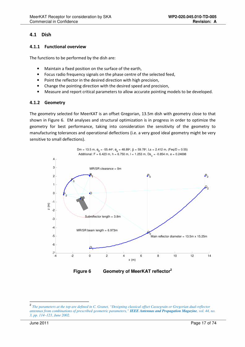
4.1.2 Geometry
The geometry selected for MeerKAT is an offset Gregorian, 13.5m dish with geometry close to that
shown in Figure 6. EM analyses and structural optimization is in progress in order to optimize the
geometry for best performance, taking into consideration the sensitivity of the geometry to
manufacturing tolerances and operational deflections (i.e. a very good ideal geometry might be very
sensitive to small deflections).
-4 -2 0 2 4 6 8 10 12 14-7
-6
-5
-4
-3
-2
-1
0
1
2
3
4
O
Q0
Q1
Q2
R0
R1
R2
P0
P1
P2
F0
Subreflector length = 3.8m
Main reflector diameter = 13.5m x 15.25m
MR/SR clearance = 0m
MR/SR beam length = 6.973m
x (m)
z (
m)
Dm = 13.5 m, θ0 = -55.44°, θe
= 48.89°, β = 59.78°, Ls = 2.412 m, (Feq/D = 0.55)
Additional: F = 6.423 m, h = 6.750 m, l = 1.253 m, Dsx = -0.854 m, e = 0.24698
Figure 6 Geometry of MeerKAT reflector2
2 The parameters at the top are defined in C. Granet, “Designing classical offset Cassegrain or Gregorian dual-reflector
antennas from combinations of prescribed geometric parameters,” IEEE Antennas and Propagation Magazine, vol. 44, no.
3, pp. 114–123, June 2002.
MeerKAT Receptor for consideration by SKA WP2-020.045.010-TD-005 Commercial in Confidence Revision: A
June 2011 Page 18 of 74
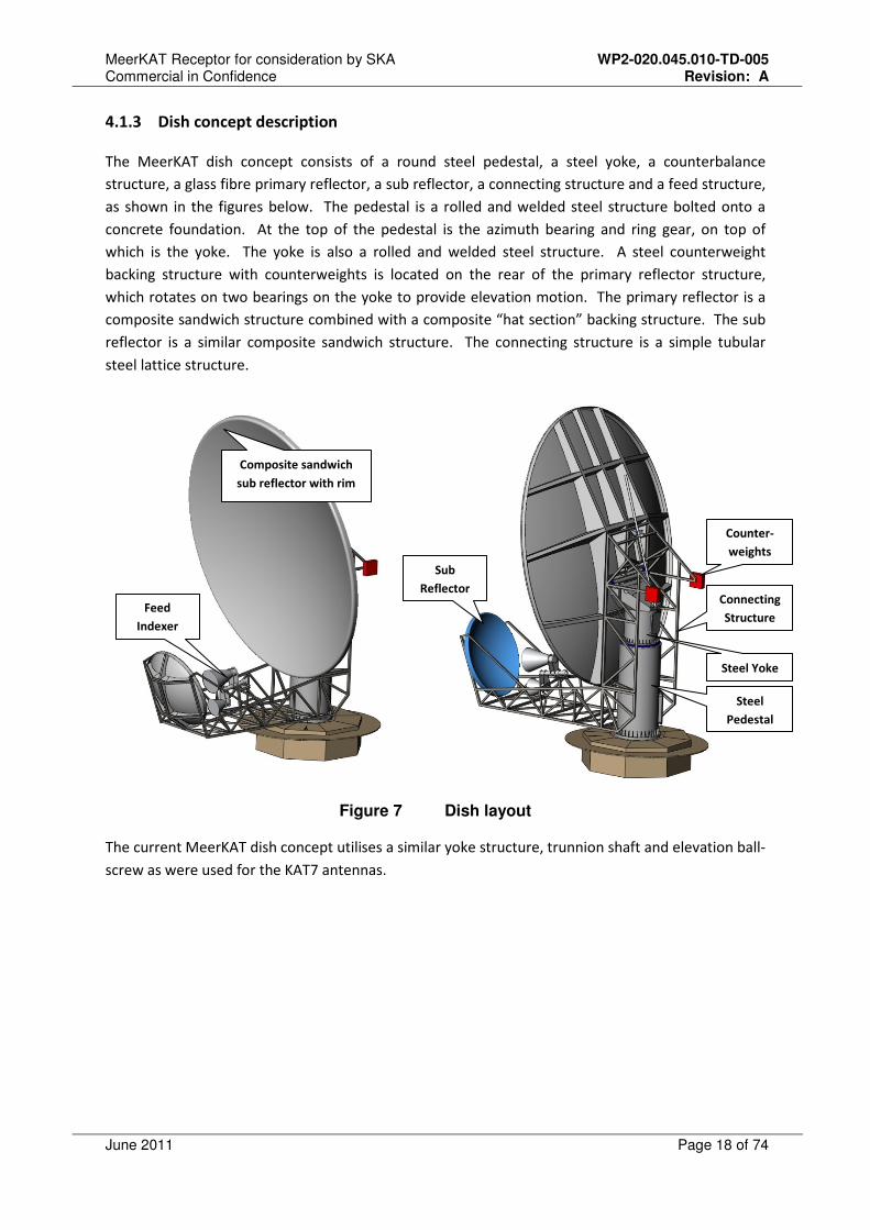
4.1.3 Dish concept description
The MeerKAT dish concept consists of a round steel pedestal, a steel yoke, a counterbalance
structure, a glass fibre primary reflector, a sub reflector, a connecting structure and a feed structure,
as shown in the figures below. The pedestal is a rolled and welded steel structure bolted onto a
concrete foundation. At the top of the pedestal is the azimuth bearing and ring gear, on top of
which is the yoke. The yoke is also a rolled and welded steel structure. A steel counterweight
backing structure with counterweights is located on the rear of the primary reflector structure,
which rotates on two bearings on the yoke to provide elevation motion. The primary reflector is a
composite sandwich structure combined with a composite “hat section” backing structure. The sub
reflector is a similar composite sandwich structure. The connecting structure is a simple tubular
steel lattice structure.
Figure 7 Dish layout
The current MeerKAT dish concept utilises a similar yoke structure, trunnion shaft and elevation ball-
screw as were used for the KAT7 antennas.
Composite sandwich
sub reflector with rim
Feed
Indexer
Steel
Pedestal
Counter-
weights
Steel Yoke
Connecting
Structure
Sub
Reflector
MeerKAT Receptor for consideration by SKA WP2-020.045.010-TD-005 Commercial in Confidence Revision: A
June 2011 Page 19 of 74
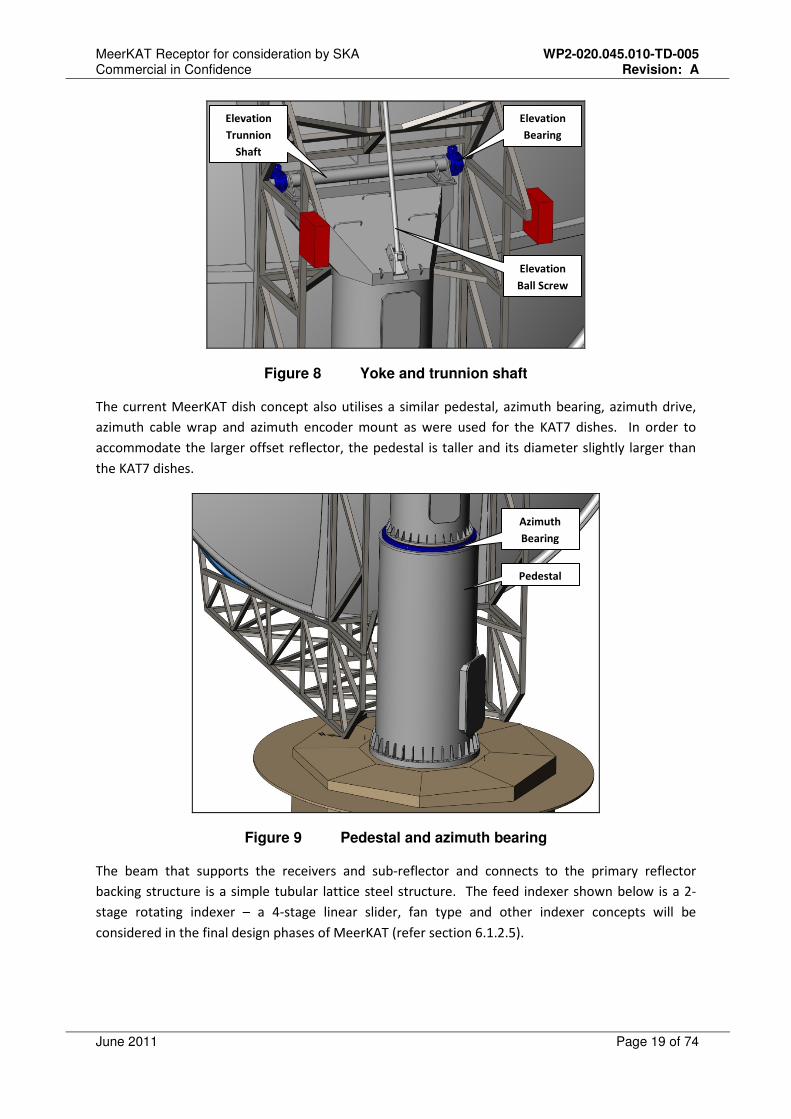
Figure 8 Yoke and trunnion shaft
The current MeerKAT dish concept also utilises a similar pedestal, azimuth bearing, azimuth drive,
azimuth cable wrap and azimuth encoder mount as were used for the KAT7 dishes. In order to
accommodate the larger offset reflector, the pedestal is taller and its diameter slightly larger than
the KAT7 dishes.
Figure 9 Pedestal and azimuth bearing
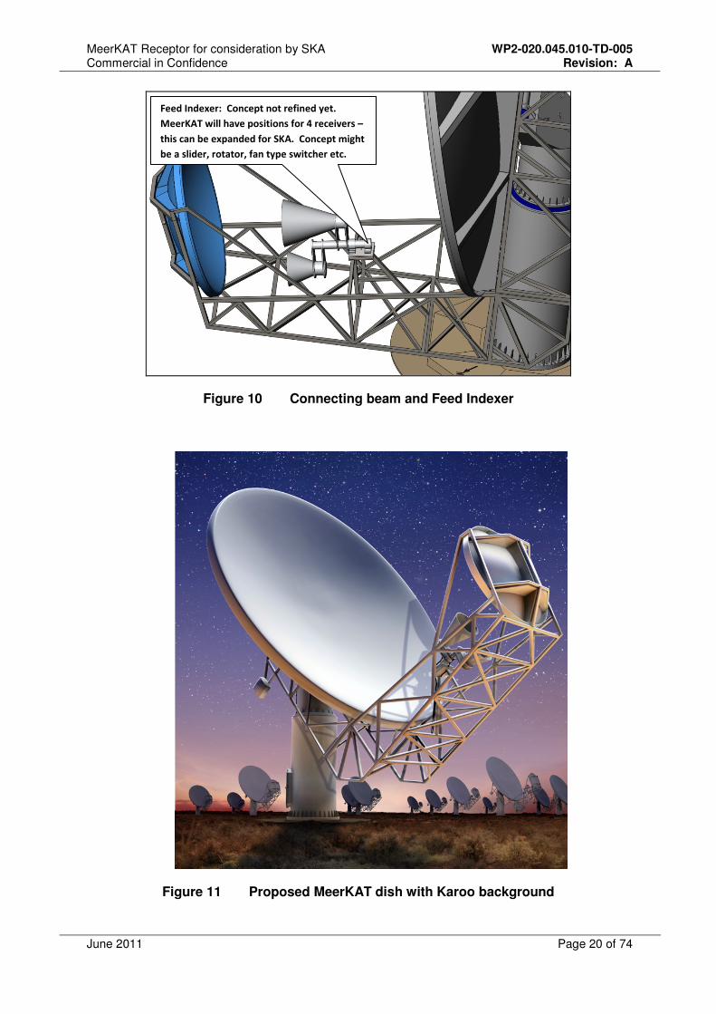
The beam that supports the receivers and sub-reflector and connects to the primary reflector
backing structure is a simple tubular lattice steel structure. The feed indexer shown below is a 2-
stage rotating indexer – a 4-stage linear slider, fan type and other indexer concepts will be
considered in the final design phases of MeerKAT (refer section 6.1.2.5).
Elevation
Bearing
Elevation
Trunnion
Shaft
Elevation
Ball Screw
Azimuth
Bearing
Pedestal
MeerKAT Receptor for consideration by SKA WP2-020.045.010-TD-005 Commercial in Confidence Revision: A
June 2011 Page 20 of 74
Figure 10 Connecting beam and Feed Indexer
Figure 11 Proposed MeerKAT dish with Karoo background
Feed Indexer: Concept not refined yet.
MeerKAT will have positions for 4 receivers –
this can be expanded for SKA. Concept might
be a slider, rotator, fan type switcher etc.

MeerKAT Receptor for consideration by SKA WP2-020.045.010-TD-005 Commercial in Confidence Revision: A
June 2011 Page 21 of 74
4.2 Receiver
The MeerKAT phase 1 receiver (L-band) placed at the secondary focus will cover the frequency range
from 1 – 1.75GHz. The receiver package will consist of the feed horn, ortho-mode transducer (OMT),
1st
stage low noise and 2nd
stage RF amplification, a calibration noise source, and control and
monitoring (CAM) unit (see Figure 12). The entire receiver package will be a single line-replaceable
unit (LRU), with its calibration and gain data stored on EEPROM in the CAM system. It will use a
Gifford-McMahon (GM) two-stage cryogenic refrigerator to cool the LNAs to a physical temperature
of approximately 20K. The cryostat vacuum chamber will operate at a pressure of <1x10⁻⁴
mbar. The
calibration noise source and 2nd
stage amplification will be located within the cryostat vacuum
chamber where it will be temperature stabilised with resistive heating. The receiver will be
connected to a vacuum pump that will generate a sufficiently low pressure until the cryo-pumping
effect from the cold head is sufficient for vacuum maintenance.
GM cooling will be used due to the improved system sensitivity and improved vacuum maintenance
properties compared to a Stirling cooling option. The estimated system sensitivity for the GM
cooling solution is approximately 300m2/K when the LNAs are cooled to 20K. This is approximately
21% better than a Stirling cooler solution (also refer to section 6.2.3).
MeerKAT Receptor for consideration by SKA WP2-020.045.010-TD-005 Commercial in Confidence Revision: A
June 2011 Page 22 of 74
L-band receiver
Horn
Linear
PSUCAM unit
GM
Coldhead
RF(H)
RF (V)
220VL-Rx
Feed Indexer
L-band Rx CAM
fibre (e
thernet)
UHF-band receiver
X-band receiver RF(H)
RF (V)
Noise switching & CAM fibre
Noise switching
fibre
RF(H)
RF (V)
Vacuum
Manifold
220V
Vacuum
Vacuum
UHF-band Rx
X-band Rx
Noise switching & CAM fibre
220V
Vacuum
Rx
Rx
Rx
Rx
Turbo Pump
Station
(low speed)
Vacuum
Rx
PedestalOutside Yoke
GM Helium
CompressorRx
Compressor /
vacuum pump
controller
Power
Power
RxEthernet
Helium Pressure
Helium
Helium
Helium
H&V LNAsOMT2ndStage
amplification
Noise Source Noise PSU RF PSUs
Power
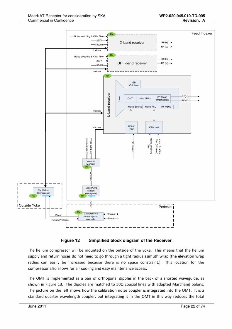
Figure 12 Simplified block diagram of the Receiver
The helium compressor will be mounted on the outside of the yoke. This means that the helium
supply and return hoses do not need to go through a tight radius azimuth wrap (the elevation wrap
radius can easily be increased because there is no space constraint.) This location for the
compressor also allows for air cooling and easy maintenance access.
The OMT is implemented as a pair of orthogonal dipoles in the back of a shorted waveguide, as
shown in Figure 13. The dipoles are matched to 50Ω coaxial lines with adapted Marchand baluns.
The picture on the left shows how the calibration noise coupler is integrated into the OMT. It is a
standard quarter wavelength coupler, but integrating it in the OMT in this way reduces the total
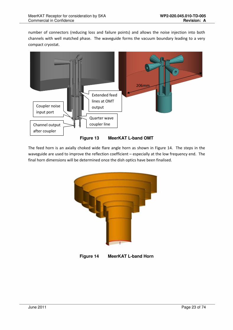
MeerKAT Receptor for consideration by SKA WP2-020.045.010-TD-005 Commercial in Confidence Revision: A
June 2011 Page 23 of 74
number of connectors (reducing loss and failure points) and allows the noise injection into both
channels with well matched phase. The waveguide forms the vacuum boundary leading to a very
compact cryostat.
Figure 13 MeerKAT L-band OMT
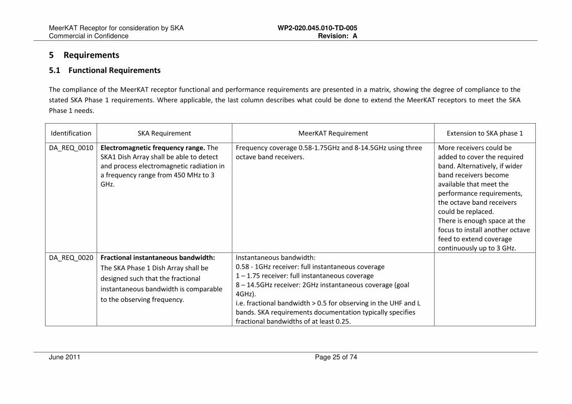
The feed horn is an axially choked wide flare angle horn as shown in Figure 14. The steps in the
waveguide are used to improve the reflection coefficient – especially at the low frequency end. The
final horn dimensions will be determined once the dish optics have been finalised.
Figure 14 MeerKAT L-band Horn
Quarter wave
coupler line
Extended feed
lines at OMT
output
Channel output
after coupler
Coupler noise
input port
206mm

MeerKAT Receptor for consideration by SKA WP2-020.045.010-TD-005 Commercial in Confidence Revision: A
June 2011 Page 24 of 74
4.3 Digitizer
The MeerKAT Digitizer sub-system is placed as close to the receiver as is practical in order to ensure
the highest quality- and most stable RF pass-band. The digitizer package performs RF, mixed signal
and digital functions. The Digitizer shares signal path interfaces with the Receiver and the Correlator
sub-systems. The RF unit provides basic signal conditioning, including RF amplification and level
control, bandpass equalization and Nyquist filtering. The digital unit directly converts RF analogue
signals into digital signals, performs digital down-conversion (and perhaps some channelization), and
outputs the results to the Correlator via a commodity Ethernet data link. The Digitizer is designed to
operate in the potentially harsh environmental conditions at its exposed location on the dish. The
package enclosure will provide EMC shielding to prevent contamination of the RF signal, and to
preserve the pristine RFI environment of the site. For more detail on the digitizer refer to section
6.3.
MeerKAT Receptor for consideration by SKA WP2-020.045.010-TD-005 Commercial in Confidence Revision: A
June 2011 Page 25 of 74
5 Requirements
5.1 Functional Requirements
The compliance of the MeerKAT receptor functional and performance requirements are presented in a matrix, showing the degree of compliance to the
stated SKA Phase 1 requirements. Where applicable, the last column describes what could be done to extend the MeerKAT receptors to meet the SKA
Phase 1 needs.
Identification SKA Requirement MeerKAT Requirement Extension to SKA phase 1
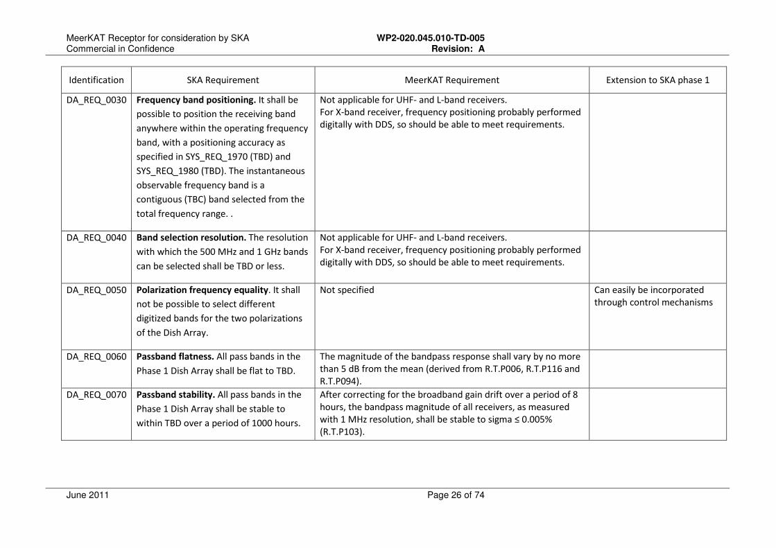
DA_REQ_0010 Electromagnetic frequency range. The
SKA1 Dish Array shall be able to detect
and process electromagnetic radiation in
a frequency range from 450 MHz to 3
GHz.
Frequency coverage 0.58-1.75GHz and 8-14.5GHz using three
octave band receivers.
More receivers could be
added to cover the required
band. Alternatively, if wider
band receivers become
available that meet the
performance requirements,
the octave band receivers
could be replaced.
There is enough space at the
focus to install another octave
feed to extend coverage
continuously up to 3 GHz.
DA_REQ_0020
Fractional instantaneous bandwidth:
The SKA Phase 1 Dish Array shall be
designed such that the fractional
instantaneous bandwidth is comparable
to the observing frequency.
Instantaneous bandwidth:
0.58 - 1GHz receiver: full instantaneous coverage
1 – 1.75 receiver: full instantaneous coverage
8 – 14.5GHz receiver: 2GHz instantaneous coverage (goal
4GHz).
i.e. fractional bandwidth > 0.5 for observing in the UHF and L
bands. SKA requirements documentation typically specifies
fractional bandwidths of at least 0.25.
MeerKAT Receptor for consideration by SKA WP2-020.045.010-TD-005 Commercial in Confidence Revision: A
June 2011 Page 26 of 74
Identification SKA Requirement MeerKAT Requirement Extension to SKA phase 1
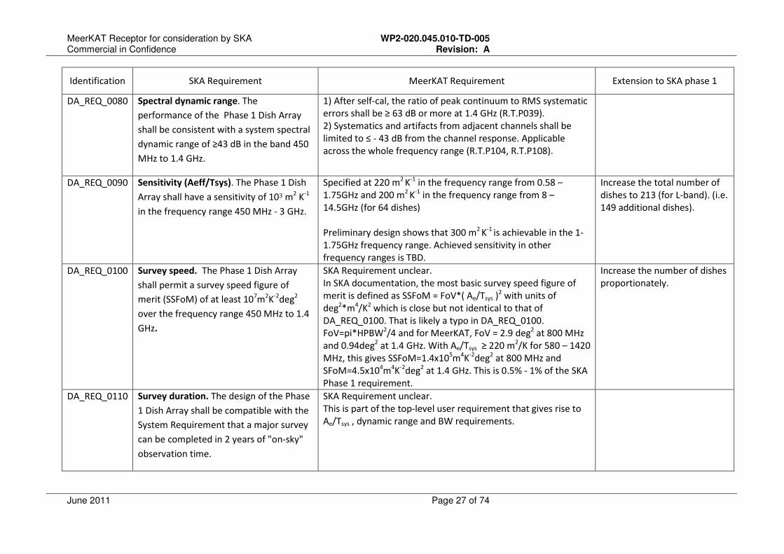
DA_REQ_0030
Frequency band positioning. It shall be
possible to position the receiving band
anywhere within the operating frequency
band, with a positioning accuracy as
specified in SYS_REQ_1970 (TBD) and
SYS_REQ_1980 (TBD). The instantaneous
observable frequency band is a
contiguous (TBC) band selected from the
total frequency range. .
Not applicable for UHF- and L-band receivers.
For X-band receiver, frequency positioning probably performed
digitally with DDS, so should be able to meet requirements.
DA_REQ_0040
Band selection resolution. The resolution
with which the 500 MHz and 1 GHz bands
can be selected shall be TBD or less.
Not applicable for UHF- and L-band receivers.
For X-band receiver, frequency positioning probably performed
digitally with DDS, so should be able to meet requirements.
DA_REQ_0050
Polarization frequency equality. It shall
not be possible to select different
digitized bands for the two polarizations
of the Dish Array.
Not specified Can easily be incorporated
through control mechanisms
DA_REQ_0060
Passband flatness. All pass bands in the
Phase 1 Dish Array shall be flat to TBD.
The magnitude of the bandpass response shall vary by no more
than 5 dB from the mean (derived from R.T.P006, R.T.P116 and
R.T.P094).
DA_REQ_0070
Passband stability. All pass bands in the
Phase 1 Dish Array shall be stable to
within TBD over a period of 1000 hours.
After correcting for the broadband gain drift over a period of 8
hours, the bandpass magnitude of all receivers, as measured
with 1 MHz resolution, shall be stable to sigma ≤ 0.005%
(R.T.P103).
MeerKAT Receptor for consideration by SKA WP2-020.045.010-TD-005 Commercial in Confidence Revision: A
June 2011 Page 27 of 74
Identification SKA Requirement MeerKAT Requirement Extension to SKA phase 1
DA_REQ_0080
Spectral dynamic range. The
performance of the Phase 1 Dish Array
shall be consistent with a system spectral
dynamic range of ≥43 dB in the band 450
MHz to 1.4 GHz.
1) After self-cal, the ratio of peak continuum to RMS systematic
errors shall be ≥ 63 dB or more at 1.4 GHz (R.T.P039).
2) Systematics and artifacts from adjacent channels shall be
limited to ≤ - 43 dB from the channel response. Applicable
across the whole frequency range (R.T.P104, R.T.P108).
DA_REQ_0090
Sensitivity (Aeff/Tsys). The Phase 1 Dish
Array shall have a sensitivity of 103 m2 K
-1
in the frequency range 450 MHz - 3 GHz.
Specified at 220 m2
K-1
in the frequency range from 0.58 –
1.75GHz and 200 m2
K-1
in the frequency range from 8 –
14.5GHz (for 64 dishes)
Preliminary design shows that 300 m2
K-1
is achievable in the 1-
1.75GHz frequency range. Achieved sensitivity in other
frequency ranges is TBD.
Increase the total number of
dishes to 213 (for L-band). (i.e.
149 additional dishes).
DA_REQ_0100
Survey speed. The Phase 1 Dish Array
shall permit a survey speed figure of
merit (SSFoM) of at least 107m
2K
-2deg
2
over the frequency range 450 MHz to 1.4
GHz.
SKA Requirement unclear.
In SKA documentation, the most basic survey speed figure of
merit is defined as SSFoM = FoV*( Ae/Tsys )2 with units of
deg2*m
4/K
2 which is close but not identical to that of
DA_REQ_0100. That is likely a typo in DA_REQ_0100.
FoV=pi*HPBW2/4 and for MeerKAT, FoV = 2.9 deg
2 at 800 MHz
and 0.94deg2 at 1.4 GHz. With Ae/Tsys ≥ 220 m
2/K for 580 – 1420
MHz, this gives SSFoM=1.4x10⁵m
4K
-2deg
2 at 800 MHz and
SFoM=4.5x10⁴m
4K
-2deg
2 at 1.4 GHz. This is 0.5% - 1% of the SKA
Phase 1 requirement.
Increase the number of dishes
proportionately.
DA_REQ_0110
Survey duration. The design of the Phase
1 Dish Array shall be compatible with the
System Requirement that a major survey
can be completed in 2 years of "on-sky"
observation time.
SKA Requirement unclear.
This is part of the top-level user requirement that gives rise to
Ae/Tsys , dynamic range and BW requirements.
MeerKAT Receptor for consideration by SKA WP2-020.045.010-TD-005 Commercial in Confidence Revision: A
June 2011 Page 28 of 74
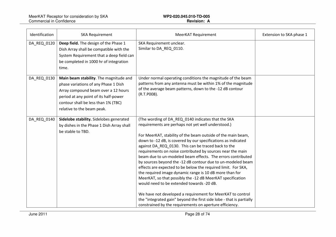
Identification SKA Requirement MeerKAT Requirement Extension to SKA phase 1
DA_REQ_0120
Deep field. The design of the Phase 1
Dish Array shall be compatible with the
System Requirement that a deep field can
be completed in 1000 hr of integration
time.
SKA Requirement unclear.
Similar to DA_REQ_0110.
DA_REQ_0130
Main beam stability. The magnitude and
phase variations of any Phase 1 Dish
Array compound beam over a 12 hours
period at any point of its half-power
contour shall be less than 1% (TBC)
relative to the beam peak.
Under normal operating conditions the magnitude of the beam
patterns from any antenna must be within 1% of the magnitude
of the average beam patterns, down to the -12 dB contour
(R.T.P008).
DA_REQ_0140
Sidelobe stability. Sidelobes generated
by dishes in the Phase 1 Dish Array shall
be stable to TBD.
(The wording of DA_REQ_0140 indicates that the SKA
requirements are perhaps not yet well understood.)
For MeerKAT, stability of the beam outside of the main beam,
down to -12 dB, is covered by our specifications as indicated
against DA_REQ_0130. This can be traced back to the
requirements on noise contributed by sources near the main
beam due to un-modeled beam effects. The errors contributed
by sources beyond the -12 dB contour due to un-modeled beam
effects are expected to be below the required limit. For SKA,
the required image dynamic range is 10 dB more than for
MeerKAT, so that possibly the -12 dB MeerKAT specification
would need to be extended towards -20 dB.
We have not developed a requirement for MeerKAT to control
the "integrated gain" beyond the first side lobe - that is partially
constrained by the requirements on aperture efficiency.
MeerKAT Receptor for consideration by SKA WP2-020.045.010-TD-005 Commercial in Confidence Revision: A
June 2011 Page 29 of 74
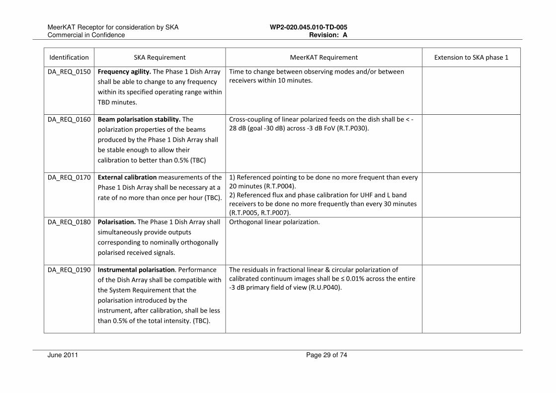
Identification SKA Requirement MeerKAT Requirement Extension to SKA phase 1
DA_REQ_0150
Frequency agility. The Phase 1 Dish Array
shall be able to change to any frequency
within its specified operating range within
TBD minutes.
Time to change between observing modes and/or between
receivers within 10 minutes.
DA_REQ_0160
Beam polarisation stability. The
polarization properties of the beams
produced by the Phase 1 Dish Array shall
be stable enough to allow their
calibration to better than 0.5% (TBC)
Cross-coupling of linear polarized feeds on the dish shall be < -
28 dB (goal -30 dB) across -3 dB FoV (R.T.P030).
DA_REQ_0170
External calibration measurements of the
Phase 1 Dish Array shall be necessary at a
rate of no more than once per hour (TBC).
1) Referenced pointing to be done no more frequent than every
20 minutes (R.T.P004).
2) Referenced flux and phase calibration for UHF and L band
receivers to be done no more frequently than every 30 minutes
(R.T.P005, R.T.P007).
DA_REQ_0180
Polarisation. The Phase 1 Dish Array shall
simultaneously provide outputs
corresponding to nominally orthogonally
polarised received signals.
Orthogonal linear polarization.
DA_REQ_0190
Instrumental polarisation. Performance
of the Dish Array shall be compatible with
the System Requirement that the
polarisation introduced by the
instrument, after calibration, shall be less
than 0.5% of the total intensity. (TBC).
The residuals in fractional linear & circular polarization of
calibrated continuum images shall be ≤ 0.01% across the entire
-3 dB primary field of view (R.U.P040).
MeerKAT Receptor for consideration by SKA WP2-020.045.010-TD-005 Commercial in Confidence Revision: A
June 2011 Page 30 of 74
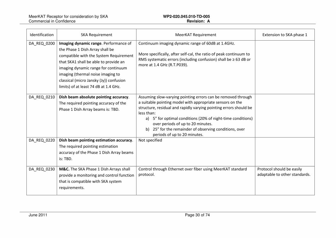
Identification SKA Requirement MeerKAT Requirement Extension to SKA phase 1
DA_REQ_0200
Imaging dynamic range. Performance of
the Phase 1 Dish Array shall be
compatible with the System Requirement
that SKA1 shall be able to provide an
imaging dynamic range for continuum
imaging (thermal noise imaging to
classical (micro Jansky (Jy)) confusion
limits) of at least 74 dB at 1.4 GHz.
Continuum imaging dynamic range of 60dB at 1.4GHz.
More specifically, after self-cal, the ratio of peak continuum to
RMS systematic errors (including confusion) shall be ≥ 63 dB or
more at 1.4 GHz (R.T.P039).
DA_REQ_0210
Dish beam absolute pointing accuracy.
The required pointing accuracy of the
Phase 1 Dish Array beams is: TBD.
Assuming slow-varying pointing errors can be removed through
a suitable pointing model with appropriate sensors on the
structure, residual and rapidly varying pointing errors should be
less than:
a) 5” for optimal conditions (20% of night-time conditions)
over periods of up to 20 minutes.
b) 25” for the remainder of observing conditions, over
periods of up to 20 minutes.
DA_REQ_0220
Dish beam pointing estimation accuracy.
The required pointing estimation
accuracy of the Phase 1 Dish Array beams
is: TBD.
Not specified
DA_REQ_0230
M&C. The SKA Phase 1 Dish Arrays shall
provide a monitoring and control function
that is compatible with SKA system
requirements.
Control through Ethernet over fiber using MeerKAT standard
protocol.
Protocol should be easily
adaptable to other standards.

MeerKAT Receptor for consideration by SKA WP2-020.045.010-TD-005 Commercial in Confidence Revision: A
June 2011 Page 31 of 74
Identification SKA Requirement MeerKAT Requirement Extension to SKA phase 1
DA_REQ_0240
M&C purpose. The monitoring and
control function shall ensure that all parts
of the system work together coherently.
All control functions, except certain local
maintenance functions, are part of the
M&C system.
Compliant.
DA_REQ_0250
M&C failure detection. The monitoring
and control function shall ensure that
failures in hardware, software or signal
transport are detected and reported.
Compliant.
DA_REQ_0260
M&C autonomy. The monitoring and
control function shall take autonomous
action to ameliorate failures where
possible and support a fail-safe
philosophy.
Subsystems shall be locally fail-safe and not rely on external
control and monitoring interfaces for safety.
DA_REQ_0270
M&C and safety. M&C shall take
autonomous action in safety critical
situations such as system power failure,
over-temperature, and storms
(dish-stowing).
Subsystems shall be locally fail-safe and not rely on external
interfaces for safety.
For MeerKAT the only exception is power failure. The receptors
assume UPS power and rely on power to stow.
Implement UPS locally at the
antenna for safety-critical
functionality.
MeerKAT Receptor for consideration by SKA WP2-020.045.010-TD-005 Commercial in Confidence Revision: A
June 2011 Page 32 of 74
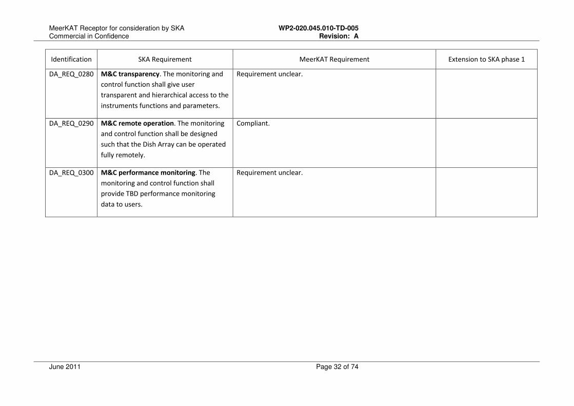
Identification SKA Requirement MeerKAT Requirement Extension to SKA phase 1
DA_REQ_0280
M&C transparency. The monitoring and
control function shall give user
transparent and hierarchical access to the
instruments functions and parameters.
Requirement unclear.
DA_REQ_0290
M&C remote operation. The monitoring
and control function shall be designed
such that the Dish Array can be operated
fully remotely.
Compliant.
DA_REQ_0300
M&C performance monitoring. The
monitoring and control function shall
provide TBD performance monitoring
data to users.
Requirement unclear.

MeerKAT Receptor for consideration by SKA WP2-020.045.010-TD-005 Commercial in Confidence Revision: A
June 2011 Page 33 of 74
Identification SKA Requirement MeerKAT Requirement Extension to SKA phase 1
DA_REQ_0310
M&C monitoring data. All Phase 1 Dish
Array subsystems shall provide
monitoring data to the monitoring and
control function (for performance
monitoring and closed-loop control
functions).
The following monitoring data shall be provided:
a) Measured pointing angles.
b) Sensors required for pointing correction.
c) Sensors required for receiver calibration.
d) Sensor reporting:
• Sensor values required for failure prediction
• Sensors required to identify faults (fault finding)
• Sensors that may indicate that the quality of the data
being captured may be negatively impacted.
• Sensors required to determine resource availability for
observation planning and scheduling
• Sensors that identify the installed configuration of the
subsystem.
• Sensors that indicate safety-critical conditions.
e) Subsystem logs
DA_REQ_0320
Real-time calibration. Design of the
Phase 1 Dish Array shall be compatible
with the requirement that SKA1 shall
provide instrumental real-time calibration
functions in all observational modes.
The following sensors will be provided for real-time calibration:
Sensor reporting required for pointing correction.
Sensor reporting required for receiver calibration.
Table 2 Compliance Matrix
MeerKAT Receptor for consideration by SKA WP2-020.045.010-TD-005 Commercial in Confidence Revision: A
June 2011 Page 34 of 74
5.2 Non-Functional Requirements
5.2.1 Manufacturing concept
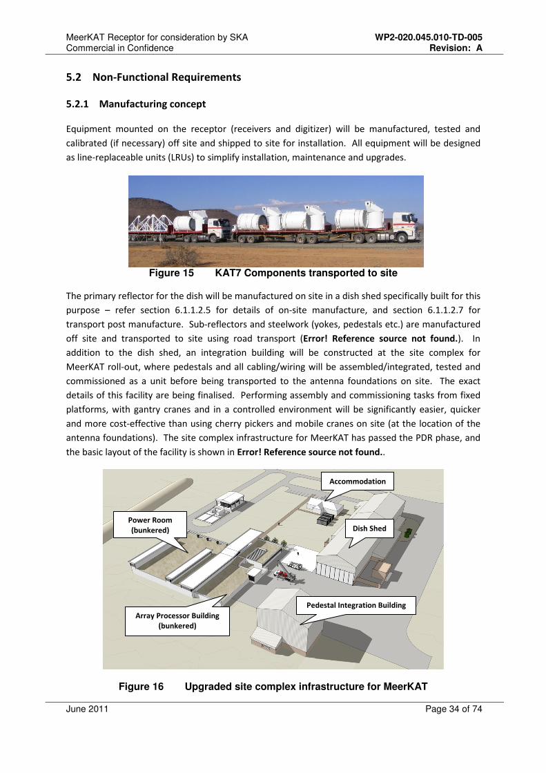
Equipment mounted on the receptor (receivers and digitizer) will be manufactured, tested and
calibrated (if necessary) off site and shipped to site for installation. All equipment will be designed
as line-replaceable units (LRUs) to simplify installation, maintenance and upgrades.
Figure 15 KAT7 Components transported to site
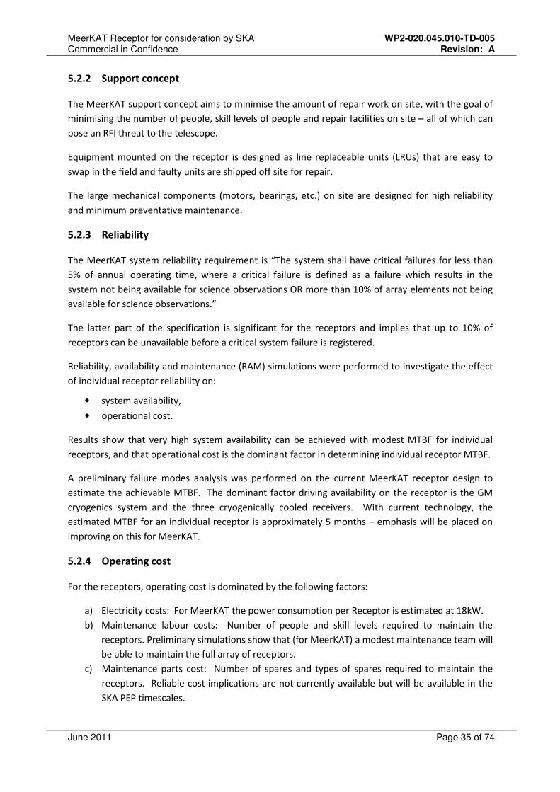
The primary reflector for the dish will be manufactured on site in a dish shed specifically built for this
purpose – refer section 6.1.1.2.5 for details of on-site manufacture, and section 6.1.1.2.7 for
transport post manufacture. Sub-reflectors and steelwork (yokes, pedestals etc.) are manufactured
off site and transported to site using road transport (Error! Reference source not found.). In
addition to the dish shed, an integration building will be constructed at the site complex for
MeerKAT roll-out, where pedestals and all cabling/wiring will be assembled/integrated, tested and
commissioned as a unit before being transported to the antenna foundations on site. The exact
details of this facility are being finalised. Performing assembly and commissioning tasks from fixed
platforms, with gantry cranes and in a controlled environment will be significantly easier, quicker
and more cost-effective than using cherry pickers and mobile cranes on site (at the location of the
antenna foundations). The site complex infrastructure for MeerKAT has passed the PDR phase, and
the basic layout of the facility is shown in Error! Reference source not found..
Figure 16 Upgraded site complex infrastructure for MeerKAT
Dish Shed
Pedestal Integration Building
Array Processor Building
(bunkered)
Accommodation
Power Room
(bunkered)
MeerKAT Receptor for consideration by SKA WP2-020.045.010-TD-005 Commercial in Confidence Revision: A
June 2011 Page 35 of 74
5.2.2 Support concept
The MeerKAT support concept aims to minimise the amount of repair work on site, with the goal of
minimising the number of people, skill levels of people and repair facilities on site – all of which can
pose an RFI threat to the telescope.
Equipment mounted on the receptor is designed as line replaceable units (LRUs) that are easy to
swap in the field and faulty units are shipped off site for repair.
The large mechanical components (motors, bearings, etc.) on site are designed for high reliability
and minimum preventative maintenance.
5.2.3 Reliability
The MeerKAT system reliability requirement is “The system shall have critical failures for less than
5% of annual operating time, where a critical failure is defined as a failure which results in the
system not being available for science observations OR more than 10% of array elements not being
available for science observations.”
The latter part of the specification is significant for the receptors and implies that up to 10% of
receptors can be unavailable before a critical system failure is registered.
Reliability, availability and maintenance (RAM) simulations were performed to investigate the effect
of individual receptor reliability on:
• system availability,
• operational cost.
Results show that very high system availability can be achieved with modest MTBF for individual
receptors, and that operational cost is the dominant factor in determining individual receptor MTBF.
A preliminary failure modes analysis was performed on the current MeerKAT receptor design to
estimate the achievable MTBF. The dominant factor driving availability on the receptor is the GM
cryogenics system and the three cryogenically cooled receivers. With current technology, the
estimated MTBF for an individual receptor is approximately 5 months – emphasis will be placed on
improving on this for MeerKAT.
5.2.4 Operating cost
For the receptors, operating cost is dominated by the following factors:
a) Electricity costs: For MeerKAT the power consumption per Receptor is estimated at 18kW.
b) Maintenance labour costs: Number of people and skill levels required to maintain the
receptors. Preliminary simulations show that (for MeerKAT) a modest maintenance team will
be able to maintain the full array of receptors.
c) Maintenance parts cost: Number of spares and types of spares required to maintain the
receptors. Reliable cost implications are not currently available but will be available in the
SKA PEP timescales.
MeerKAT Receptor for consideration by SKA WP2-020.045.010-TD-005 Commercial in Confidence Revision: A
June 2011 Page 36 of 74
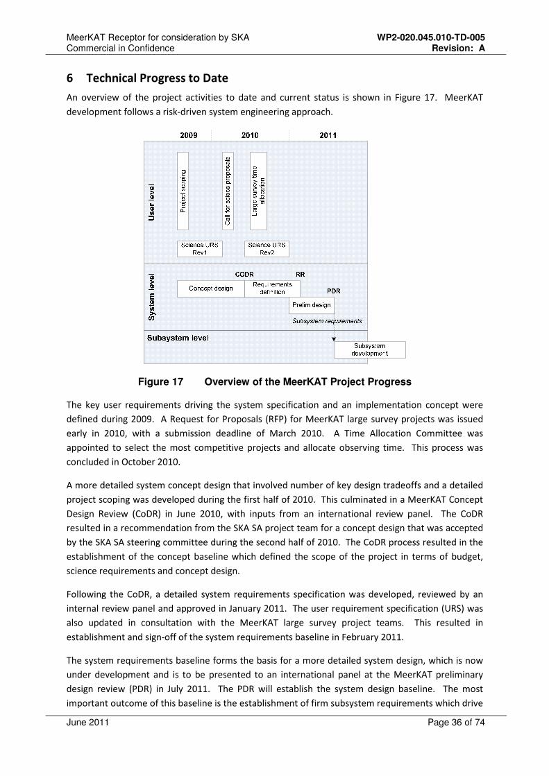
6 Technical Progress to Date
An overview of the project activities to date and current status is shown in Figure 17. MeerKAT
development follows a risk-driven system engineering approach.
Figure 17 Overview of the MeerKAT Project Progress
The key user requirements driving the system specification and an implementation concept were
defined during 2009. A Request for Proposals (RFP) for MeerKAT large survey projects was issued
early in 2010, with a submission deadline of March 2010. A Time Allocation Committee was
appointed to select the most competitive projects and allocate observing time. This process was
concluded in October 2010.
A more detailed system concept design that involved number of key design tradeoffs and a detailed
project scoping was developed during the first half of 2010. This culminated in a MeerKAT Concept
Design Review (CoDR) in June 2010, with inputs from an international review panel. The CoDR
resulted in a recommendation from the SKA SA project team for a concept design that was accepted
by the SKA SA steering committee during the second half of 2010. The CoDR process resulted in the
establishment of the concept baseline which defined the scope of the project in terms of budget,
science requirements and concept design.
Following the CoDR, a detailed system requirements specification was developed, reviewed by an
internal review panel and approved in January 2011. The user requirement specification (URS) was
also updated in consultation with the MeerKAT large survey project teams. This resulted in
establishment and sign-off of the system requirements baseline in February 2011.
The system requirements baseline forms the basis for a more detailed system design, which is now
under development and is to be presented to an international panel at the MeerKAT preliminary
design review (PDR) in July 2011. The PDR will establish the system design baseline. The most
important outcome of this baseline is the establishment of firm subsystem requirements which drive

MeerKAT Receptor for consideration by SKA WP2-020.045.010-TD-005 Commercial in Confidence Revision: A
June 2011 Page 37 of 74
the subsystem development process. Infrastructure for the MeerKAT telescope will be rolled out
using a system engineering approach. Telescope requirements (such as antenna foundation stability
etc.) are included in the infrastructure requirements documents. MeerKAT infrastructure will have a
critical design review (CDR) in August / September 2011 and infrastructure roll-out is scheduled for
2011 and 2012.
6.1 Dish
As part of the MeerKAT concept exploration and prototyping exercises, the following dish
development phases were completed:
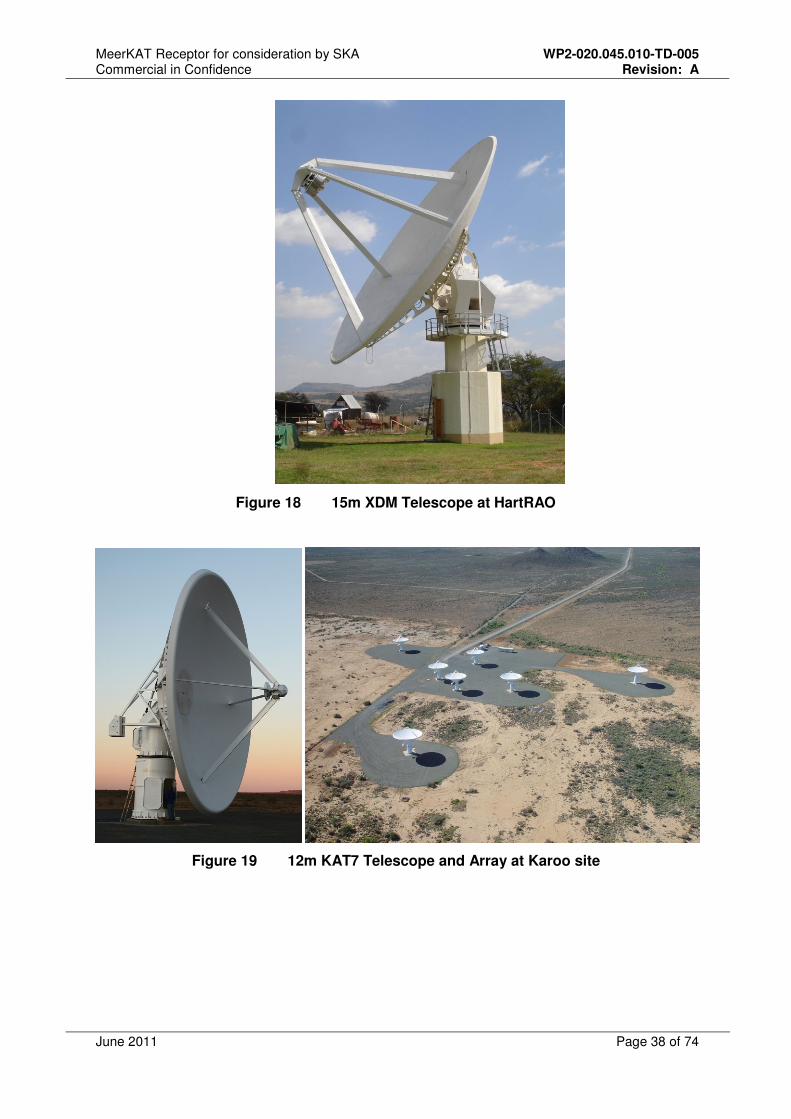
• XDM: Experimental Development model, 15m symmetric prime focus dish with f/d of 0.5
constructed at HartRAO.
• KAT7: Seven 12m dishes in the Northern Cape, South Africa. These are symmetric prime
focus dishes with an f/d of 0.38 (optimized for single pixel feeds). A modified version of the
composite reflectors was used for these dishes, building on the experience gained on XDM.
• MeerKAT: MeerKAT will be 64 offset Gregorian dishes. A concept study was completed in
July 2010 and more detailed work is underway at present to validate the use of composite
reflectors for MeerKAT.
The phases mentioned above provided essential learning in a number of areas that are crucial for
the detail design phase of MeerKAT dishes (these will be discussed in more detail in subsequent
sections):
• On-site manufacture of single piece reflectors made of a composite material using a vacuum
infusion process,
• Understanding and evaluating reflective surfaces for composite dishes,
• Understanding accuracies for composite reflectors and additional work that needs to be
done,
• Transport of reflectors – different strategies for various transport distances,
• The pedestal, servos, and control unit. This includes the concept of a single motor drive per
axis with an anti-backlash mechanism and the ball-screw concept for elevation,
• Cable routing principles in order to minimize electromagnetic interference (EMI),
• Lightning protection concept,
• “Design for manufacture” and techniques to be used to minimise construction time on site
in the Karoo.
MeerKAT Receptor for consideration by SKA WP2-020.045.010-TD-005 Commercial in Confidence Revision: A
June 2011 Page 38 of 74
Figure 18 15m XDM Telescope at HartRAO
Figure 19 12m KAT7 Telescope and Array at Karoo site
MeerKAT Receptor for consideration by SKA WP2-020.045.010-TD-005 Commercial in Confidence Revision: A
June 2011 Page 39 of 74
6.1.1 XDM and KAT7 areas of key learning
6.1.1.1 FEA Analyses of Antenna Structures (Dishes)
6.1.1.1.1 Loadcases
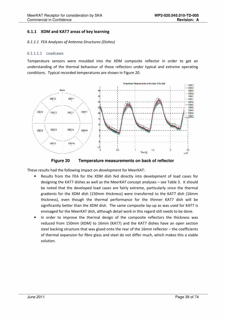
Temperature sensors were moulded into the XDM composite reflector in order to get an
understanding of the thermal behaviour of these reflectors under typical and extreme operating
conditions. Typical recorded temperatures are shown in Figure 20.
Figure 20 Temperature measurements on back of reflector
These results had the following impact on development for MeerKAT:
• Results from the FEA for the XDM dish fed directly into development of load cases for
designing the KAT7 dishes as well as the MeerKAT concept analyses – see Table 3. It should
be noted that the developed load cases are fairly extreme, particularly since the thermal
gradients for the XDM dish (150mm thickness) were transferred to the KAT7 dish (16mm
thickness), even though the thermal performance for the thinner KAT7 dish will be
significantly better than the XDM dish. The same composite lay-up as was used for KAT7 is
envisaged for the MeerKAT dish, although detail work in this regard still needs to be done.
• In order to improve the thermal design of the composite reflectors the thickness was
reduced from 150mm (XDM) to 16mm (KAT7) and the KAT7 dishes have an open section
steel backing structure that was glued onto the rear of the 16mm reflector – the coefficients
of thermal expansion for fibre glass and steel do not differ much, which makes this a viable
solution.
MeerKAT Receptor for consideration by SKA WP2-020.045.010-TD-005 Commercial in Confidence Revision: A
June 2011 Page 40 of 74
Load case no Load case description
1 Gravity, 0º azimuth, 0º elevation
2 Wind, 0º azimuth, 0º elevation
3 Wind, 60º azimuth, 0º elevation
4 Wind, 90º azimuth, 0º elevation
5 Temperature, 40ºC overall from 20ºC.
6 Temperature, -5ºC overall from 20ºC.
7 Temperature, 55ºC front, 40ºC rear, from 20ºC.
8 Temperature, 55ºC rear, 40ºC front, from 20ºC.
9 Temperature, 55ºC top, 40ºC bottom, from 20ºC.
A Gravity, wind from front, overall -5ºC from +20ºC reference, typical of a
very cold winters night. (LC1+LC2+LC6)
B Gravity, wind from side, overall -5ºC from +20ºC reference, typical of a
very cold winters night. (LC1+LC4+LC6)
C Gravity, wind from front, overall +40ºC from +20ºC reference, typical of a
hot summers day. (LC1+LC2+LC5)
D
Gravity, wind from side, overall +40ºC, dish front at +55 ºC from +20ºC
reference, typical of a hot summers day with sun shining full on front of
dish. (LC1+LC4+LC7)
E
Gravity, wind at 60º angle, overall +40ºC, dish rear at +55 ºC from +20ºC
reference, typical of a hot summers day with sun shining full on rear of
dish. (LC1+LC3+LC8)
F Gravity, wind from front, overall +40ºC, dish top at +55 ºC from +20ºC
reference, typical of a hot summers day with sun at zenith. (LC1+LC2+LC9)
Table 3 Load Cases for analysing Dishes
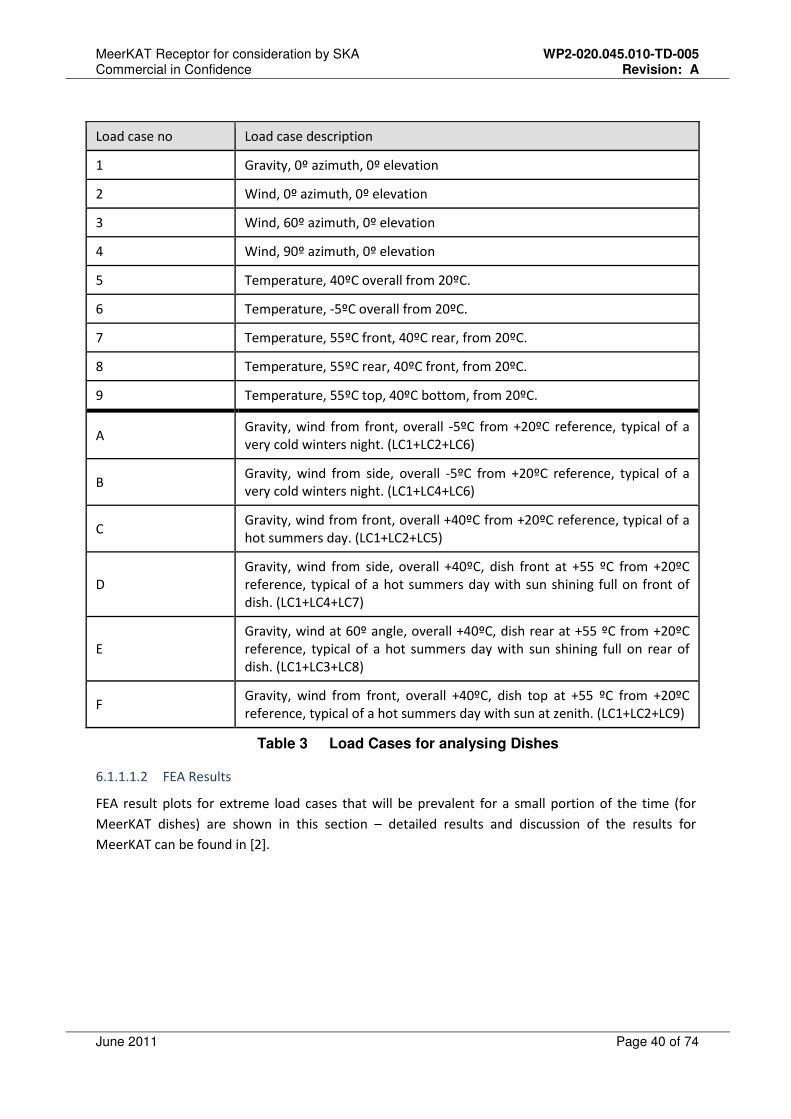
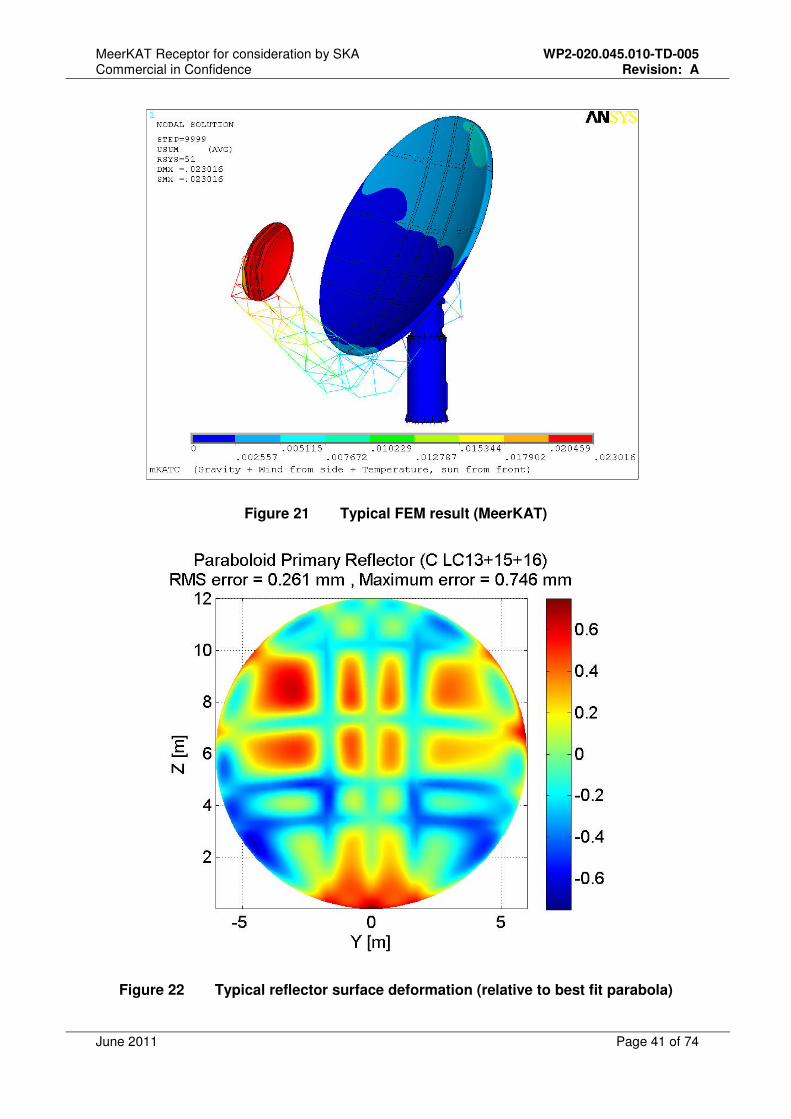
6.1.1.1.2 FEA Results
FEA result plots for extreme load cases that will be prevalent for a small portion of the time (for
MeerKAT dishes) are shown in this section – detailed results and discussion of the results for
MeerKAT can be found in [2].
MeerKAT Receptor for consideration by SKA WP2-020.045.010-TD-005 Commercial in Confidence Revision: A
June 2011 Page 41 of 74
Figure 21 Typical FEM result (MeerKAT)
Figure 22 Typical reflector surface deformation (relative to best fit parabola)
MeerKAT Receptor for consideration by SKA WP2-020.045.010-TD-005 Commercial in Confidence Revision: A
June 2011 Page 42 of 74
6.1.1.2 Composite Reflectors – “design for manufacture”
Key “design for manufacture” considerations related to the antenna to be taken into account for
MeerKAT include:
• Optimization of the mechanical design of the structure to facilitate modularisation and quick
roll-out (once the manufacturing process has been qualified).
• Development of a one-piece reflector (adapted as the baseline concept for MeerKAT) and
sub-reflector.
• Consider all implications of using one-piece reflectors, such as transport considerations
(maximum size that can be transported, implications for equipment available to erect the
structure, impact of environmental conditions on construction schedules, etc) – some of the
unique challenges are addressed in section 6.1.1.2.7.
• Low tooling cost: One of the reasons composites were chosen is due to its applicability and
associated low tooling costs.
• Choice of specific composite: Glass fibre is the composite material of choice mainly because
the thermal coefficient of expansion is similar to that of steel for a typical KAT7 laminate
(this reduces the risk of thermal distortions) and its low cost.
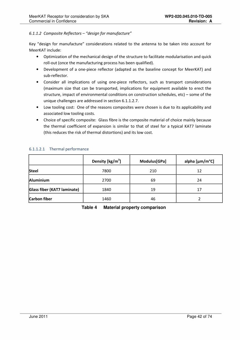
6.1.1.2.1 Thermal performance
Density [kg/m3] Modulus[GPa] alpha [µm/m°C]
Steel 7800 210 12
Aluminium 2700 69 24
Glass fiber (KAT7 laminate) 1840 19 17
Carbon fiber 1460 46 2
Table 4 Material property comparison
MeerKAT Receptor for consideration by SKA WP2-020.045.010-TD-005 Commercial in Confidence Revision: A
June 2011 Page 43 of 74
Table 5 Reflector weight/cost comparison for various materials
Table 4 and Table 5 show that:
• Glass fibre is similar to Aluminium when considering reflector weight and cost.
• The coefficient of thermal expansion of a typical KAT7 glass fibre laminate is similar to that
of steel.
The detailed mould design work (referred to in section 6.1.3.2) will consider the following key issues
in order to minimize thermal effects on the reflector:
• Temperature during manufacture of the reflector: This should be close to the expected
nominal operational temperature of the structure in service.
• Thermal control during all the stages of the mould manufacture and dish manufacture
processes.
• Curing of composite reflector: Curing at a high temperature results in a product with high
strength. The following will be considered here:
o Required curing temperature/time in order to ensure that no creep will occur when
the dish is in operation. The creep tests (that were conducted as part of an
extensive material qualification programme in SA) described in section 6.1.3.1 will
form an integral part of this. Additional creep tests will be conducted on samples at
higher temperatures than the composite reflectors will experience in operation in
order to mitigate the risk of creep at high temperatures.
o Ideally one wants to cure the composite reflector at an average operational
temperature in order to minimize the thermal deformations – the average
operational temperature is however typically too low to achieve good transfer (resin
viscosity is an issue) and will result in a low strength reflector susceptible to creep. It
will be investigated whether it will be possible to cure the composite reflector at 30
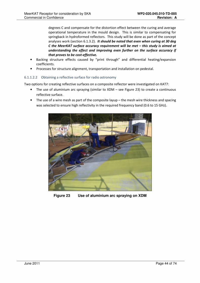
MeerKAT Receptor for consideration by SKA WP2-020.045.010-TD-005 Commercial in Confidence Revision: A
June 2011 Page 44 of 74
degrees C and compensate for the distortion effect between the curing and average
operational temperature in the mould design. This is similar to compensating for
springback in hydroformed reflectors. This study will be done as part of the concept
analyses work (section 6.1.3.2). It should be noted that even when curing at 30 deg
C the MeerKAT surface accuracy requirement will be met – this study is aimed at
understanding the effect and improving even further on the surface accuracy if
that proves to be cost-effective.
• Backing structure effects caused by “print through” and differential heating/expansion
coefficients.
• Processes for structure alignment, transportation and installation on pedestal.
6.1.1.2.2 Obtaining a reflective surface for radio astronomy
Two options for creating reflective surfaces on a composite reflector were investigated on KAT7:
• The use of aluminium arc spraying (similar to XDM – see Figure 23) to create a continuous
reflective surface.
• The use of a wire mesh as part of the composite layup – the mesh wire thickness and spacing
was selected to ensure high reflectivity in the required frequency band (0.6 to 15 GHz).
Figure 23 Use of aluminium arc spraying on XDM
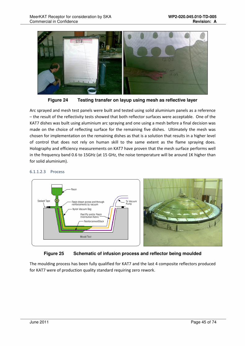
MeerKAT Receptor for consideration by SKA WP2-020.045.010-TD-005 Commercial in Confidence Revision: A
June 2011 Page 45 of 74
Figure 24 Testing transfer on layup using mesh as reflective layer
Arc sprayed and mesh test panels were built and tested using solid aluminium panels as a reference
– the result of the reflectivity tests showed that both reflector surfaces were acceptable. One of the
KAT7 dishes was built using aluminium arc spraying and one using a mesh before a final decision was
made on the choice of reflecting surface for the remaining five dishes. Ultimately the mesh was
chosen for implementation on the remaining dishes as that is a solution that results in a higher level
of control that does not rely on human skill to the same extent as the flame spraying does.
Holography and efficiency measurements on KAT7 have proven that the mesh surface performs well
in the frequency band 0.6 to 15GHz (at 15 GHz, the noise temperature will be around 1K higher than
for solid aluminium).
6.1.1.2.3 Process
Figure 25 Schematic of infusion process and reflector being moulded
The moulding process has been fully qualified for KAT7 and the last 4 composite reflectors produced
for KAT7 were of production quality standard requiring zero rework.
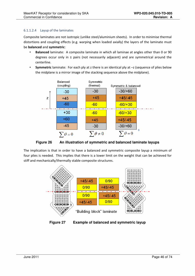
MeerKAT Receptor for consideration by SKA WP2-020.045.010-TD-005 Commercial in Confidence Revision: A
June 2011 Page 46 of 74
6.1.1.2.4 Layup of the laminates
Composite laminates are not isotropic (unlike steel/aluminium sheets). In order to minimise thermal
distortions and coupling effects (e.g. warping when loaded axially) the layers of the laminate must
be balanced and symmetric:
• Balanced laminate: A composite laminate in which all laminae at angles other than 0 or 90
degrees occur only in ± pairs (not necessarily adjacent) and are symmetrical around the
centerline.
• Symmetric laminate: For each ply at z there is an identical ply at –z (sequence of plies below
the midplane is a mirror image of the stacking sequence above the midplane).
Figure 26 An illustration of symmetric and balanced laminate layups
The implication is that in order to have a balanced and symmetric composite layup a minimum of
four plies is needed. This implies that there is a lower limit on the weight that can be achieved for
stiff and mechanically/thermally stable composite structures.
Figure 27 Example of balanced and symmetric layup

MeerKAT Receptor for consideration by SKA WP2-020.045.010-TD-005 Commercial in Confidence Revision: A
June 2011 Page 47 of 74
6.1.1.2.5 On-site manufacture of composite reflectors
The XDM experience provided confidence that the concept of moulding composite reflectors on site
(employing the vacuum infusion process) was feasible. A more controlled environment was used for
moulding KAT7 reflectors. This enabled the routine manufacture of reflectors with surface
accuracies in the order of 1mm RMS (under operational conditions). For KAT7, the focus was on
establishing a reliable production process that could be scaled up for “mass production” for
MeerKAT and possibly SKA phase 1. In order to limit costs during the prototyping phases towards
MeerKAT, KAT7 reflectors were moulded using a fairly low-cost mould, and therefore the
manufacture of reflectors for MeerKAT that meet the 1mm surface accuracy is considered a low risk
procedure. The tolerance build-up will be discussed in 6.1.1.2.6. In order to mould composite
reflectors on site one requires a reasonably clean working environment (shed type structure) and
thermal control in order to keep the mould at constant temperature during initial setup and when
moulding a reflector.
Figure 28 KAT7 reflector and backing structure taken of mould at Karoo site
6.1.1.2.6 Composite reflector tolerance build-up and mould options
Initial discussion on achieving the reflector surface accuracy will be focussed on two competing
mould options:
• Option 1 (Pattern-based): Manufacture a mould as per breakdown below (i.e. KAT7):
o Machine a pattern from aluminium
o Use pattern to manufacture identical composite mould segments
o Assemble segments to create a composite mould with steel backing structure
• Option 2 (Non-pattern based): High quality mould – will likely be used for MeerKAT
o Machine all mould segments from aluminium
o Assemble segments to create a mould
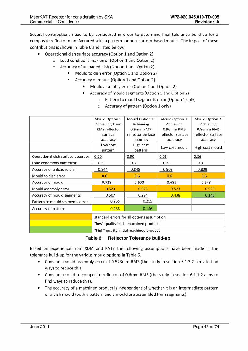
MeerKAT Receptor for consideration by SKA WP2-020.045.010-TD-005 Commercial in Confidence Revision: A
June 2011 Page 48 of 74
Several contributions need to be considered in order to determine final tolerance build-up for a
composite reflector manufactured with a pattern- or non-pattern-based mould. The impact of these
contributions is shown in Table 6 and listed below:
• Operational dish surface accuracy (Option 1 and Option 2)
o Load conditions max error (Option 1 and Option 2)
o Accuracy of unloaded dish (Option 1 and Option 2)
� Mould to dish error (Option 1 and Option 2)
� Accuracy of mould (Option 1 and Option 2)
• Mould assembly error (Option 1 and Option 2)
• Accuracy of mould segments (Option 1 and Option 2)
o Pattern to mould segments error (Option 1 only)
o Accuracy of pattern (Option 1 only)
Mould Option 1:
Achieving 1mm
RMS reflector
surface
accuracy
Mould Option 1:
Achieving
0.9mm RMS
reflector surface
accuracy
Mould Option 2:
Achieving
0.96mm RMS
reflector surface
accuracy
Mould Option 2:
Achieving
0.86mm RMS
reflector surface
accuracy
Low cost
pattern
High cost
pattern Low cost mould High cost mould
Operational dish surface accuracy 0.99 0.90 0.96 0.86
Load conditions max error 0.3 0.3 0.3 0.3
Accuracy of unloaded dish 0.944 0.848 0.909 0.809
Mould to dish error 0.6 0.6 0.6 0.6
Accuracy of mould 0.728 0.600 0.682 0.543
Mould assembly error 0.523 0.523 0.523 0.523
Accuracy of mould segments 0.507 0.294 0.438 0.146
Pattern to mould segments error 0.255 0.255
Accuracy of pattern 0.438 0.146
standard errors for all options assumption
"low" quality initial machined product
"high" quality initial machined product
Table 6 Reflector Tolerance build-up
Based on experience from XDM and KAT7 the following assumptions have been made in the
tolerance build-up for the various mould options in Table 6.
• Constant mould assembly error of 0.523mm RMS (the study in section 6.1.3.2 aims to find
ways to reduce this).
• Constant mould to composite reflector of 0.6mm RMS (the study in section 6.1.3.2 aims to
find ways to reduce this).
• The accuracy of a machined product is independent of whether it is an intermediate pattern
or a dish mould (both a pattern and a mould are assembled from segments).

MeerKAT Receptor for consideration by SKA WP2-020.045.010-TD-005 Commercial in Confidence Revision: A
June 2011 Page 49 of 74
What can further be seen from Table 6 is that:
• In order to improve the final surface accuracy of the composite reflector under nominal
operating conditions, the initial machined component accuracy needs to be improved
considerably (for both options 1 and 2).
• Going from a “low-cost” pattern-based mould (option 1) to a high cost non-pattern based
mould (option 2) improves the final in-operation reflector accuracy from 1mm RMS to
0.86mm RMS.
The preliminary findings listed above will be studied in detail in the MeerKAT concept analyses work
package (refer section 6.1.3.2) that will determine the advantages and feasibilities of the above
options further, and investigate ways of improving on the factors that have the highest contribution
to surface error.
6.1.1.2.7 Composite reflector transport post-manufacture
Transport distances for KAT7 and MeerKAT reflectors from the on-site manufacturing facility to the
antenna pedestals are fairly short (maximum of about 15 km). In the open Karoo landscape, the
transport of the entire reflector with backup structure on a custom-built trailer is therefore feasible.
In the event that longer transport distances are unavoidable, and transporting a 13.5m offset
reflector is impractical, the composite reflector can be designed to be moulded in 2 halves (it is not a
one-piece reflector that gets “cut up” and re-assembled elsewhere). Transporting these two halves
on standard roads is feasible and simple installation process is therefore still feasible. A concept
design for this option does exist, although it is not presented here.
Figure 29 KAT7 dish being transported
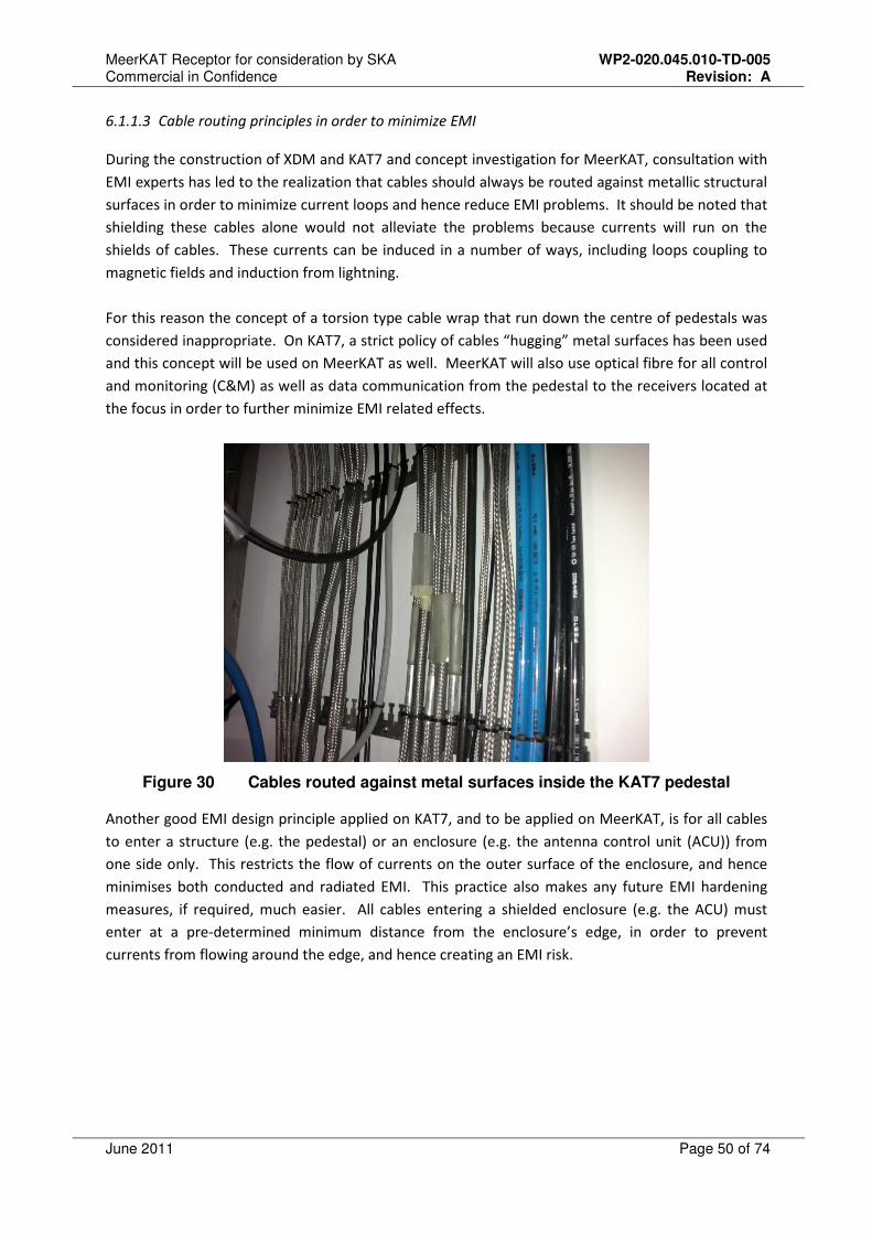
MeerKAT Receptor for consideration by SKA WP2-020.045.010-TD-005 Commercial in Confidence Revision: A
June 2011 Page 50 of 74
6.1.1.3 Cable routing principles in order to minimize EMI
During the construction of XDM and KAT7 and concept investigation for MeerKAT, consultation with
EMI experts has led to the realization that cables should always be routed against metallic structural
surfaces in order to minimize current loops and hence reduce EMI problems. It should be noted that
shielding these cables alone would not alleviate the problems because currents will run on the
shields of cables. These currents can be induced in a number of ways, including loops coupling to
magnetic fields and induction from lightning.
For this reason the concept of a torsion type cable wrap that run down the centre of pedestals was
considered inappropriate. On KAT7, a strict policy of cables “hugging” metal surfaces has been used
and this concept will be used on MeerKAT as well. MeerKAT will also use optical fibre for all control
and monitoring (C&M) as well as data communication from the pedestal to the receivers located at
the focus in order to further minimize EMI related effects.
Figure 30 Cables routed against metal surfaces inside the KAT7 pedestal
Another good EMI design principle applied on KAT7, and to be applied on MeerKAT, is for all cables
to enter a structure (e.g. the pedestal) or an enclosure (e.g. the antenna control unit (ACU)) from
one side only. This restricts the flow of currents on the outer surface of the enclosure, and hence
minimises both conducted and radiated EMI. This practice also makes any future EMI hardening
measures, if required, much easier. All cables entering a shielded enclosure (e.g. the ACU) must
enter at a pre-determined minimum distance from the enclosure’s edge, in order to prevent
currents from flowing around the edge, and hence creating an EMI risk.
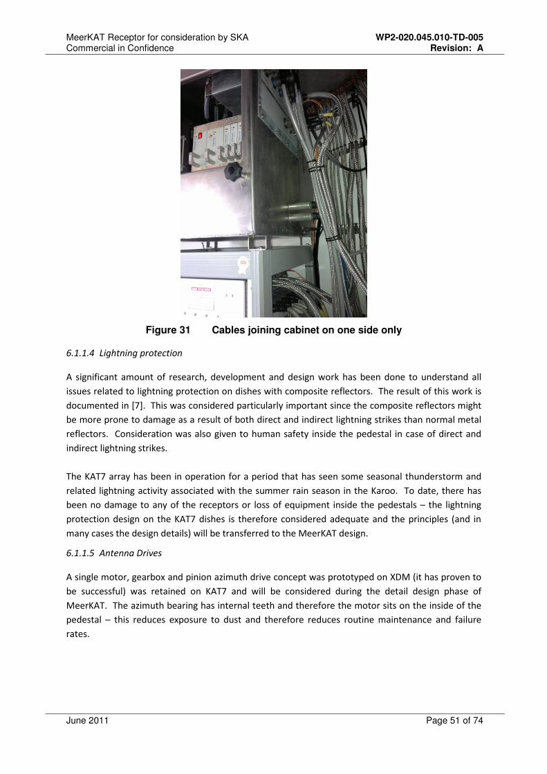
MeerKAT Receptor for consideration by SKA WP2-020.045.010-TD-005 Commercial in Confidence Revision: A
June 2011 Page 51 of 74
Figure 31 Cables joining cabinet on one side only
6.1.1.4 Lightning protection
A significant amount of research, development and design work has been done to understand all
issues related to lightning protection on dishes with composite reflectors. The result of this work is
documented in [7]. This was considered particularly important since the composite reflectors might
be more prone to damage as a result of both direct and indirect lightning strikes than normal metal
reflectors. Consideration was also given to human safety inside the pedestal in case of direct and
indirect lightning strikes.
The KAT7 array has been in operation for a period that has seen some seasonal thunderstorm and
related lightning activity associated with the summer rain season in the Karoo. To date, there has
been no damage to any of the receptors or loss of equipment inside the pedestals – the lightning
protection design on the KAT7 dishes is therefore considered adequate and the principles (and in
many cases the design details) will be transferred to the MeerKAT design.
6.1.1.5 Antenna Drives
A single motor, gearbox and pinion azimuth drive concept was prototyped on XDM (it has proven to
be successful) was retained on KAT7 and will be considered during the detail design phase of
MeerKAT. The azimuth bearing has internal teeth and therefore the motor sits on the inside of the
pedestal – this reduces exposure to dust and therefore reduces routine maintenance and failure
rates.
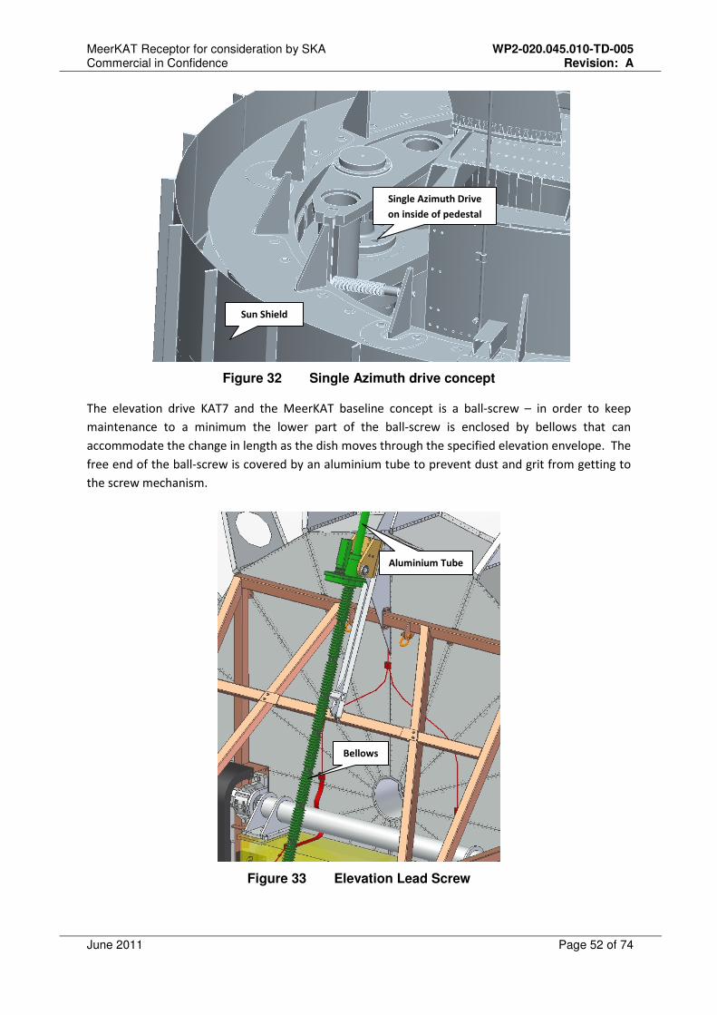
MeerKAT Receptor for consideration by SKA WP2-020.045.010-TD-005 Commercial in Confidence Revision: A
June 2011 Page 52 of 74
Figure 32 Single Azimuth drive concept
The elevation drive KAT7 and the MeerKAT baseline concept is a ball-screw – in order to keep
maintenance to a minimum the lower part of the ball-screw is enclosed by bellows that can
accommodate the change in length as the dish moves through the specified elevation envelope. The
free end of the ball-screw is covered by an aluminium tube to prevent dust and grit from getting to
the screw mechanism.
Figure 33 Elevation Lead Screw
Single Azimuth Drive
on inside of pedestal
Sun Shield
Bellows
Aluminium Tube

MeerKAT Receptor for consideration by SKA WP2-020.045.010-TD-005 Commercial in Confidence Revision: A
June 2011 Page 53 of 74
6.1.1.6 Thermal Management
A cylindrical passive sunshield mounted coaxially 100mm from the pedestal (see Figure 32) was used
on KAT7 to prevent thermal gradients in the pedestal that would cause large pointing errors. This
has proven to be a cheap, simple solution to dealing with thermal distortions on the dish pedestal.
Provision has been made for 12 thermal sensors that will be installed on the yoke of the KAT7
antennas – the yoke does not have passive shields so it is subject to differential temperature
gradients. The sensors will be used to test whether improvements on KAT7 pointing can be achieved
through corrections based on the sensor readings. This will provide valuable learning towards
implementing an improved pointing model scheme for MeerKAT.
6.1.2 Concept study towards MeerKAT
A concept feasibility study was conducted in July 2010 – this work was documented in detail [2] and
will not be repeated here. The study was based on the concept design described in section 4.1.3.
The structural aspects of the concept were analysed using a finite element model with simulated
load cases. The load cases were selected to include the effects of gravity, thermal changes, wind &
water loading at different elevation pointing angles. The following design parameters were
investigated as part of the analysis:
• The environmental effect on pointing accuracy and surface accuracy [2],
• The effect of using different material configurations for the reflectors [4],
• Servo requirements [5], [6],
• Material strength requirements [4],
• Manufacturing options for the reflectors and the antenna [4],
• Costing and Technical challenge study between offset and prime focus antennas [2].
The following five key aspects of the concept exploration phase for MeerKAT are described in some
detail below:
• Offset Gregorian vs. Prime Focus dishes,
• Reflector shaping (Offset Gregorian dishes),
• Feed-low vs. Feed-high (Offset Gregorian dishes),
• Stow position for offset dishes,
• Feed indexer.
6.1.2.1 Offset Gregorian vs. Prime Focus dishes
Concept studies presented at the MeerKAT CoDR [11] showed that offset Gregorian dishes have at
least 2K lower spill-over contribution to the system temperature than prime focus dishes, and will
have about 10% higher aperture efficiency (this is in comparison to a prime focus dish fed with an
oversized, well optimised octave band horn, as was used on KAT7.) The CoDR study showed that for
a given receiver temperature, eighty 13.5m or sixty-four 14.7m prime focus dishes or sixty-four
13.5m offset Gregorian dishes would have about the same sensitivity. There is very little difference
in the system cost for the two prime focus options, and the Gregorian option is about 8% more

MeerKAT Receptor for consideration by SKA WP2-020.045.010-TD-005 Commercial in Confidence Revision: A
June 2011 Page 54 of 74
expensive. The Offset Gregorian design has, however, a number of advantages over prime focus
dishes (which at this stage are difficult to translate to capital and operational costs):
• Offset Gregorian has better control over inner sidelobes (and are more rotationally
symmetric, improving dynamic range) than Prime Focus dishes.
• Offset Gregorian has better overall sidelobe performance (important for RFI from
satellites) than Prime Focus dishes.
• Offset Gregorian has unblocked aperture and is more amenable to receiver upgrades (it
is, for example, less sensitive to increased spill-over due to variations in beam width for
possible wideband feed upgrades).
• With Offset Gregorian dishes, receivers are in a less hostile environment than Prime
Focus dishes (contained within the antenna structure rather than exposed at the apex).
• Access to receivers at the secondary focus position provided by Offset Gregorian dishes
is much more convenient – the use of cranes and cherry pickers can be largely
eliminated resulting in saving in construction and operational cost. This applies
particularly to the feed-low concept.
• Implementation of feed indexer feasible on an Offset Gregorian dish and limited on
prime focus dishes due to weight and other restrictions.
It should be noted that one of the major disadvantages of the feed-low Offset Gregorian dish is that
the elevation range lower limit is reduced to 15 degrees (0 - 90 degrees elevation range is readily
achievable with prime focus dishes).
Prime Focus designs on dishes of diameter of 15m or less, can likely accommodate only two
receivers with a rather complex receiver rotator at the apex as a result of size, weight and EM
considerations. In operation one would therefore have to change receivers manually on all antennas
to observe a different frequency band, which would result in lost telescope time and increased
operation cost. Considering all of the above SKA SA decided to implement Offset Gregorian dishes
for MeerKAT as that would have the highest science return.
6.1.2.2 Reflector Shaping
SKA SA is in the process of completing a study to evaluate whether the MeerKAT dual reflectors
should be shaped or not. The main advantages and disadvantages of shaping are considered to be:
• Advantages of shaping
o Higher aperture efficiency achievable for shaped surfaces,
o Less diffraction for shaped surfaces on the sub-reflector - less oscillation in pointing
as a function of frequency.
• Disadvantages of shaping
o Higher inner sidelobes,
o Higher sensitivity to feed beam shape,
o Electromagnetic performance might be more sensitive to general mechanical
tolerances because a smaller portion of the sub-reflector is used to reflect the
majority of the feed pattern,
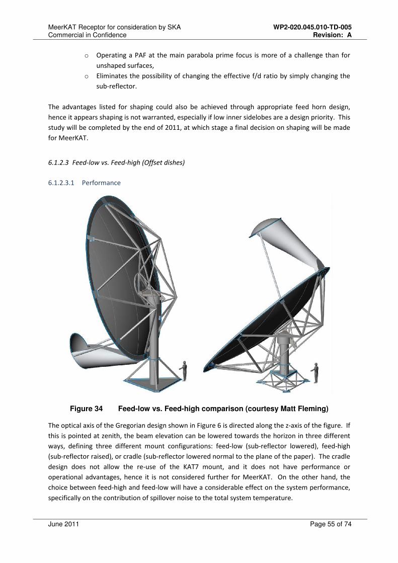
MeerKAT Receptor for consideration by SKA WP2-020.045.010-TD-005 Commercial in Confidence Revision: A
June 2011 Page 55 of 74
o Operating a PAF at the main parabola prime focus is more of a challenge than for
unshaped surfaces,
o Eliminates the possibility of changing the effective f/d ratio by simply changing the
sub-reflector.
The advantages listed for shaping could also be achieved through appropriate feed horn design,
hence it appears shaping is not warranted, especially if low inner sidelobes are a design priority. This
study will be completed by the end of 2011, at which stage a final decision on shaping will be made
for MeerKAT.
6.1.2.3 Feed-low vs. Feed-high (Offset dishes)
6.1.2.3.1 Performance
Figure 34 Feed-low vs. Feed-high comparison (courtesy Matt Fleming)
The optical axis of the Gregorian design shown in Figure 6 is directed along the z-axis of the figure. If
this is pointed at zenith, the beam elevation can be lowered towards the horizon in three different
ways, defining three different mount configurations: feed-low (sub-reflector lowered), feed-high
(sub-reflector raised), or cradle (sub-reflector lowered normal to the plane of the paper). The cradle
design does not allow the re-use of the KAT7 mount, and it does not have performance or
operational advantages, hence it is not considered further for MeerKAT. On the other hand, the
choice between feed-high and feed-low will have a considerable effect on the system performance,
specifically on the contribution of spillover noise to the total system temperature.

MeerKAT Receptor for consideration by SKA WP2-020.045.010-TD-005 Commercial in Confidence Revision: A
June 2011 Page 56 of 74
Consider the far field pattern cut for the default system as shown in Figure 35. This pattern is
generated with a typical feed with a 13dB taper on the Offset Gregorian design shown in Figure 6. In
the feed-low configuration the feed spillover passing below the sub-reflector will illuminate the
ground at 300K. In the feed-high configuration the sub-reflector illumination passing over the main
reflector will illuminate the ground at 300K. For both cases the antenna back-lobe (the sub-reflector
spillover passing by the bottom of the main reflector) will illuminate the ground, but this is a
relatively small contribution.
The main performance differentiator between the two configurations lies in the fact that it is
possible to shield the feed spill-over with a small extension to the sub-reflector as shown in Figure
36. (In this example, the sub-reflector area increases from 12.9m2 to 15.1m
2.) This significantly
reduces the feed spill-over as shown by the red curve in Figure 35. As expected, the side-lobe due to
the sub-reflector spill-over past the top edge of the main dish is increased, but this effect can be
reduced by shaping the extension such that the extra energy is added in the low side-lobe region
around θ = 60°. An interesting positive side-effect is that the extension increases the total aperture
efficiency by between 3 and 4%. This is believed to be due to the reduction of the diffraction at the
bottom rim of the sub-reflector which is the area with the smallest radius of curvature on the sub-
reflector. The effect of the extension can be seen by looking at the predicted spill-over tipping
curves in Figure 37 – over most of the elevation angles the feed-low configuration (with extension)
has at least 2K less spill-over noise than the feed-high configuration (no extension). For the very
sensitive MeerKAT system (with a system temperature of the order of 20K), this corresponds to
about 10% increase in sensitivity.
The equivalent shielding for the feed-high configuration would require extending the main reflector
by a few meters, which carries a significant mechanical design penalty. It has been suggested to use
a vertical cylindrical shroud (from point P1 toward O in Figure 6). While this would block sub-
reflector spillover past the main dish, it will also reflect the feed spillover back to ground (instead of
having this on sky) for a large section of the elevation range. Feed-high shielding has not been
pursued in detail, and the feed-high (with extension) trace in Figure 37 is shown for completeness
only – and has no bearing on the discussion here.
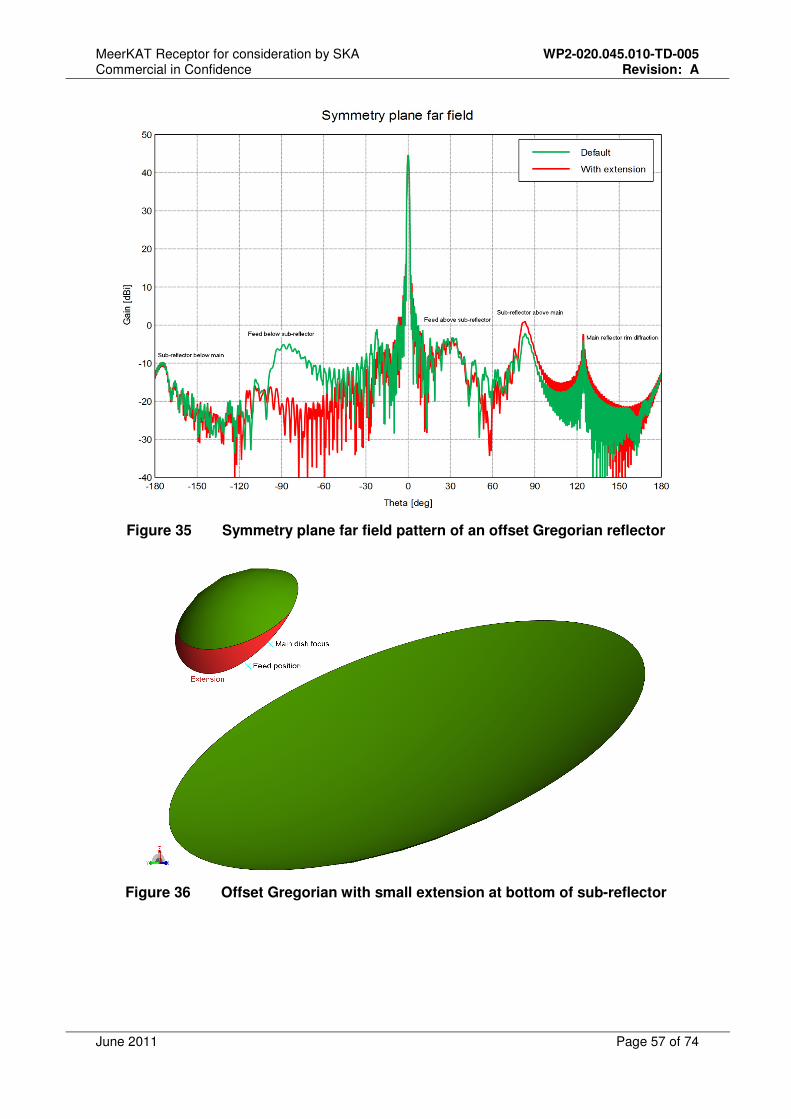
MeerKAT Receptor for consideration by SKA WP2-020.045.010-TD-005 Commercial in Confidence Revision: A
June 2011 Page 57 of 74
Figure 35 Symmetry plane far field pattern of an offset Gregorian reflector
Figure 36 Offset Gregorian with small extension at bottom of sub-reflector
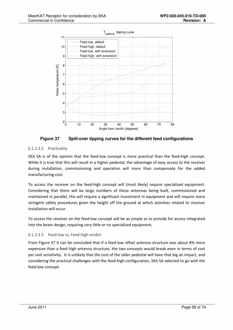
MeerKAT Receptor for consideration by SKA WP2-020.045.010-TD-005 Commercial in Confidence Revision: A
June 2011 Page 58 of 74
0 10 20 30 40 50 60 70 802
3
4
5
6
7
8
9
10
11
Angle from zenith [degrees]
Nois
e t
em
pera
ture
[K
]
Tspillover
tipping curve
Feed low, default
Feed high, default
Feed low, with extension
Feed high, with extension
Figure 37 Spill-over tipping curves for the different feed configurations
6.1.2.3.2 Practicality
SKA SA is of the opinion that the feed-low concept is more practical than the feed-high concept.
While it is true that this will result in a higher pedestal, the advantage of easy access to the receiver
during installation, commissioning and operation will more than compensate for the added
manufacturing cost.
To access the receiver on the feed-high concept will (most likely) require specialized equipment.
Considering that there will be large numbers of these antennas being built, commissioned and
maintained in parallel, this will require a significant investment in equipment and will require more
stringent safety procedures given the height off the ground at which activities related to receiver
installation will occur.
To access the receiver on the feed-low concept will be as simple as to provide for access integrated
into the beam design, requiring very little or no specialized equipment.
6.1.2.3.3 Feed-low vs. Feed-high verdict
From Figure 37 it can be concluded that if a feed-low offset antenna structure was about 8% more
expensive than a feed high antenna structure, the two concepts would break even in terms of cost
per unit sensitivity. It is unlikely that the cost of the taller pedestal will have that big an impact, and
considering the practical challenges with the feed-high configuration, SKA SA selected to go with the
feed-low concept.
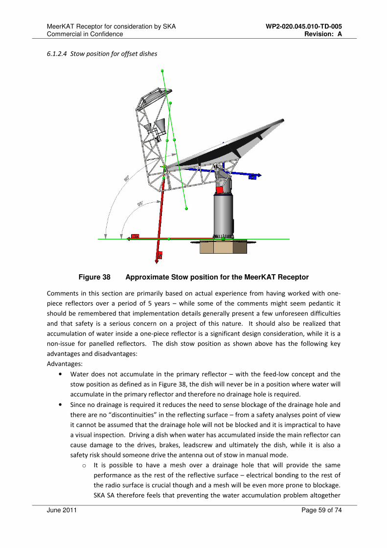
MeerKAT Receptor for consideration by SKA WP2-020.045.010-TD-005 Commercial in Confidence Revision: A
June 2011 Page 59 of 74
6.1.2.4 Stow position for offset dishes
Figure 38 Approximate Stow position for the MeerKAT Receptor
Comments in this section are primarily based on actual experience from having worked with one-
piece reflectors over a period of 5 years – while some of the comments might seem pedantic it
should be remembered that implementation details generally present a few unforeseen difficulties
and that safety is a serious concern on a project of this nature. It should also be realized that
accumulation of water inside a one-piece reflector is a significant design consideration, while it is a
non-issue for panelled reflectors. The dish stow position as shown above has the following key
advantages and disadvantages:
Advantages:
• Water does not accumulate in the primary reflector – with the feed-low concept and the
stow position as defined as in Figure 38, the dish will never be in a position where water will
accumulate in the primary reflector and therefore no drainage hole is required.
• Since no drainage is required it reduces the need to sense blockage of the drainage hole and
there are no “discontinuities” in the reflecting surface – from a safety analyses point of view
it cannot be assumed that the drainage hole will not be blocked and it is impractical to have
a visual inspection. Driving a dish when water has accumulated inside the main reflector can
cause damage to the drives, brakes, leadscrew and ultimately the dish, while it is also a
safety risk should someone drive the antenna out of stow in manual mode.
o It is possible to have a mesh over a drainage hole that will provide the same
performance as the rest of the reflective surface – electrical bonding to the rest of
the radio surface is crucial though and a mesh will be even more prone to blockage.
SKA SA therefore feels that preventing the water accumulation problem altogether

MeerKAT Receptor for consideration by SKA WP2-020.045.010-TD-005 Commercial in Confidence Revision: A
June 2011 Page 60 of 74
is the best way to go, especially since the offset concept lends itself to achieving this
goal.
o On KAT7 dishes an over-current check is built into the elevation drive that can
determine when the resistance to drive out of stow is higher than normal – if this
situation is triggered it is assumed that this is due to water accumulation and the
dish goes into error mode. It should be noted that over-current in this context
refers to a higher current than expected to start moving the dish when in stow
position and by no means the maximum current the drive is rated for. While this
works quite well, it is better to prevent the need for this altogether as preventing
the need for over-current monitor will result in a more robust system.
Disadvantages:
• Not traditional “birdbath” stow position – therefore higher forces due to wind-induced
moments on the structure and foundation.
o When considering the disadvantage above it should be noted that designing the dish
to survive a 160 km/h wind in the position as shown in Figure 38 does not present a
huge cost premium over the cost associated with traditional birdbath stow, while it
will result in a simpler and more robust antenna control solution and a safer design.

MeerKAT Receptor for consideration by SKA WP2-020.045.010-TD-005 Commercial in Confidence Revision: A
June 2011 Page 61 of 74
6.1.2.5 Feed Indexer
The MeerKAT dish will host at least 4 feeds simultaneously in a structure referred to as the “feed
indexer”. Three of the planned receiver sizes and weight budgets are shown in Figure 39, Figure 40
and Figure 41. The 4th
receiver is unspecified at this stage.
Figure 39 L-band (1 – 1.75GHz) Receiver envelope
Figure 40 UHF-band (0.58 – 1.015GHz) Receiver envelope
Figure 41 X-band (8 – 14.5GHz) Receiver envelope
80 kg weight budget
160 kg weight budget
50 kg weight budget

MeerKAT Receptor for consideration by SKA WP2-020.045.010-TD-005 Commercial in Confidence Revision: A
June 2011 Page 62 of 74
Figure 42 Schematic diagram of feed indexer
A schematic diagram of the feed indexer is shown in Figure 42, showing a layout appropriate for a
linear slider or rotational fan type indexer. The red star represents the focus of the antenna and the
yellow stars the foci of the receivers (i.e. position that needs to be aligned with the red star by feed
indexer). Practical considerations affecting the choice of indexer mechanism include:
• Bending of cables and hoses.
• The effect on the antenna structure of moving the centre of mass of the receivers and
indexer.
• Environmental and RFI shielding opportunities.
6.1.3 Work in Progress for MeerKAT
6.1.3.1 Composite Material Qualification
SKA SA is busy with qualification testing of the construction materials for a composite reflector and
is conducting a series of accelerated strength and durability tests to ensure that the composite
material would not present any long term durability problems and that the composites will meet the
operational requirements over the intended service life of the telescope. The quality of the
reflective surface, forming part of a fibre glass reinforced thermosetting polymer matrix laminate,
provides the radio performance of the reflector. The qualification tests ensure that any degradation,
occurring as a result of inherent material deficiencies, is well understood and quantified. The
following areas are covered by the qualification programme:

MeerKAT Receptor for consideration by SKA WP2-020.045.010-TD-005 Commercial in Confidence Revision: A
June 2011 Page 63 of 74
6.1.3.1.1 Geometrical stability of the reflective surface
• Post-cure shrinkage (reference standard ASTM D2566) – contract placed on MMS to
determine the shrinkage of the resin system on a test mould.
• Creep (reference standard ASTM D2990) – a series of tests is currently taking place at the
CSIR to measure the creep characteristics of the material.
6.1.3.1.2 Mechanical integrity of the reflective surface
• Erosion (reference standards ASTM D3170 & MIL-STD-810G 510) – the CSIR has proposed a
test method, combining the ASTM and MIL-STD, to determine the effects of long term
exposure to “blowing sand” on the material of the dish.
• Corrosion (reference standard MIL-STD-810G 509) – the aluminium mesh used as the
reflective surface was subjected to a salt fog test – the mesh was used in a reflectivity test
panel and no effect on the radio frequency reflectivity could be measured. The panel will
now be subjected to the environmental and radio quality tests as described in section
6.1.3.1.3.
• Static strength (Thermal/Mechanical loading) – a series of tests were conducted at the CSIR
to determine the mechanical properties of the dish material – tensile properties in
accordance with ASTM D3029, shear properties in accordance with ASTM D4255 and
compressive properties in accordance with ASTM D6641.
• Impact resistance (reference standard MIL-STD-810G 509) – the resistance of the material to
hail damage was tested and no visible damage could be detected – the CSIR is performing a
more detailed investigation to determine whether mechanical damage was done by the hail
test.
• Fatigue life (reference standard ASTM D3039) - a series of tests were conducted at the CSIR
to determine the fatigue properties of the dish material.
• Backing Structure Adhesive bond integrity – a test is planned to determine the effectiveness
of the bond between the dish and backing structure in accordance with ASTM C297.
6.1.3.1.3 Resin/paint system dielectric loss factor
• To determine the effects of environmental conditions on the dielectric performance of the
material, sample panels were fabricated for comparative tests. The dielectric loss of each
panel in comparison to an ideal aluminium reflector was measured by EMSS and HartRAO
using a dual-switched Dicke radiometer operating at 15 GHz (see Figure 43). Excess noise
temperature was measured using this instrumentation. The panels will now be subjected to
standard environmental tests.
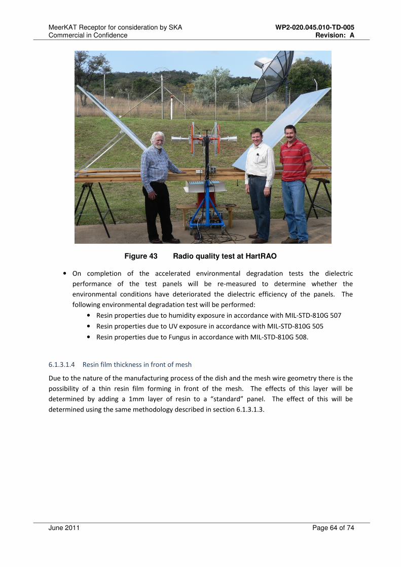
MeerKAT Receptor for consideration by SKA WP2-020.045.010-TD-005 Commercial in Confidence Revision: A
June 2011 Page 64 of 74
Figure 43 Radio quality test at HartRAO
• On completion of the accelerated environmental degradation tests the dielectric
performance of the test panels will be re-measured to determine whether the
environmental conditions have deteriorated the dielectric efficiency of the panels. The
following environmental degradation test will be performed:
• Resin properties due to humidity exposure in accordance with MIL-STD-810G 507
• Resin properties due to UV exposure in accordance with MIL-STD-810G 505
• Resin properties due to Fungus in accordance with MIL-STD-810G 508.
6.1.3.1.4 Resin film thickness in front of mesh
Due to the nature of the manufacturing process of the dish and the mesh wire geometry there is the
possibility of a thin resin film forming in front of the mesh. The effects of this layer will be
determined by adding a 1mm layer of resin to a “standard” panel. The effect of this will be
determined using the same methodology described in section 6.1.3.1.3.
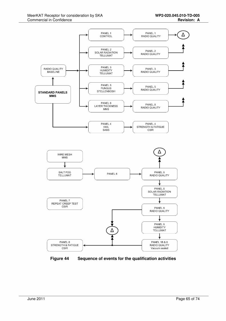
MeerKAT Receptor for consideration by SKA WP2-020.045.010-TD-005 Commercial in Confidence Revision: A
June 2011 Page 65 of 74
Figure 44 Sequence of events for the qualification activities

MeerKAT Receptor for consideration by SKA WP2-020.045.010-TD-005 Commercial in Confidence Revision: A
June 2011 Page 66 of 74
6.1.3.2 MeerKAT Concept Analyses
The following will be addressed in this phase – this will be the last work package to be completed
before detailed design work on the MeerKAT dishes commences.
• Mould design: This study will investigate options to reduce the number of steps in
getting to the final mould setup (therefore improving the surface accuracy of the
mould), and will investigate ways of mitigating factors that have the highest
contribution to reflector surface error. This will improve the final surface accuracy of
the reflector. A detailed design (including required cooling) will be done and
manufacturing data-packs produced.
• Asymmetric curing distortions: This will focus on understanding the curing
distortions applicable to offset reflectors that might have a bigger impact on the final
surface accuracy than on symmetric reflectors. Scale model reflectors (offset) will be
constructed, the mould and final products will be measured, and a FEA model will be
built to allow modelling of these effects. This qualified model will then be used in
the design of dishes for MeerKAT.
• Carbon fibre cost: This study will compare the cost of a carbon and fibre glass
designs, taking into account issues such as the thermal mismatch between
composite materials and steel, and potential galvanic issues introduced by the use of
carbon. It will also investigate pricing of carbon composites delivered to South Africa
in comparison to the cost of these products in the US and Canada.
• Offset antenna wind load investigation: This will be a CFD study to determine the
wind loading on the selected geometry for the MeerKAT dish, and validate these
results with either published results or wind tunnel tests.
• Offset antenna alignment strategy: This study will take inputs from work being
done on the sensitivity of electromagnetic performance to mechanical tolerances,
and investigate how to practically verify installation tolerances on site. This needs to
be done early, as one might need “targets” or references on the mould that are
repeatable on all dishes and that can be used for installation. The use of quadrant
detectors, strain gauges, or similar instruments, in order to determine and correct
for structural deformations while in operation will also be investigated.
6.1.3.3 Optics optimization
An EM study combined with a structural FEA study will be completed by the end of July 2011 in
order to optimize the optical configuration of the MeerKAT dishes, while also considering structural
aspects. The optical configuration shown in Figure 6 is the most likely baseline geometry at this
stage.
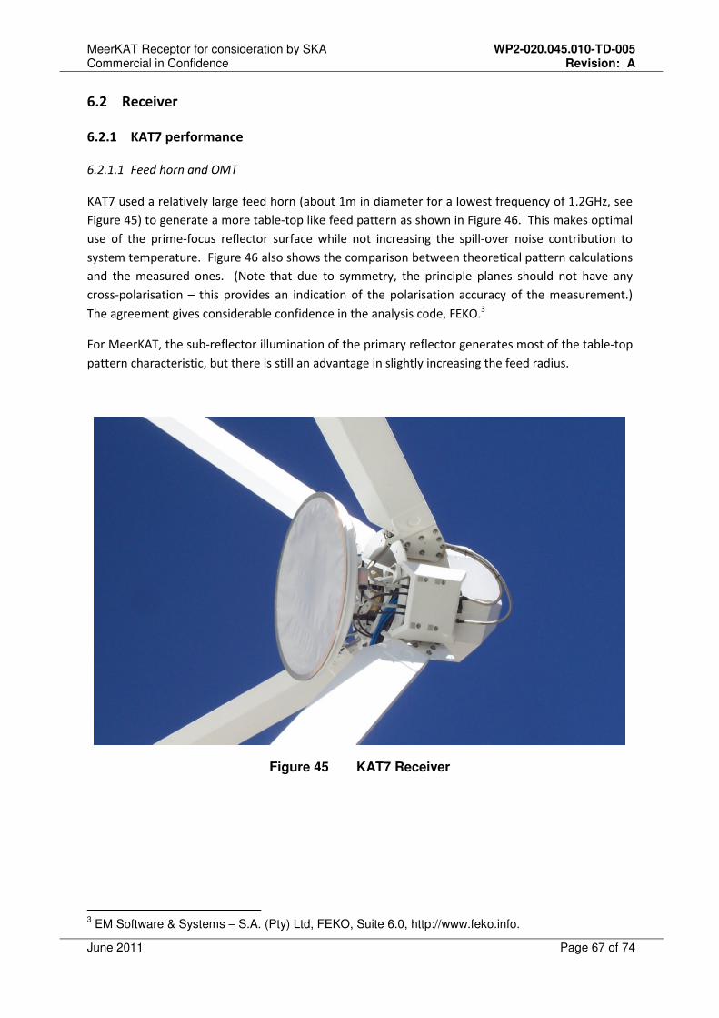
MeerKAT Receptor for consideration by SKA WP2-020.045.010-TD-005 Commercial in Confidence Revision: A
June 2011 Page 67 of 74
6.2 Receiver
6.2.1 KAT7 performance
6.2.1.1 Feed horn and OMT
KAT7 used a relatively large feed horn (about 1m in diameter for a lowest frequency of 1.2GHz, see
Figure 45) to generate a more table-top like feed pattern as shown in Figure 46. This makes optimal
use of the prime-focus reflector surface while not increasing the spill-over noise contribution to
system temperature. Figure 46 also shows the comparison between theoretical pattern calculations
and the measured ones. (Note that due to symmetry, the principle planes should not have any
cross-polarisation – this provides an indication of the polarisation accuracy of the measurement.)
The agreement gives considerable confidence in the analysis code, FEKO.3
For MeerKAT, the sub-reflector illumination of the primary reflector generates most of the table-top
pattern characteristic, but there is still an advantage in slightly increasing the feed radius.
Figure 45 KAT7 Receiver
3 EM Software & Systems – S.A. (Pty) Ltd, FEKO, Suite 6.0, http://www.feko.info.
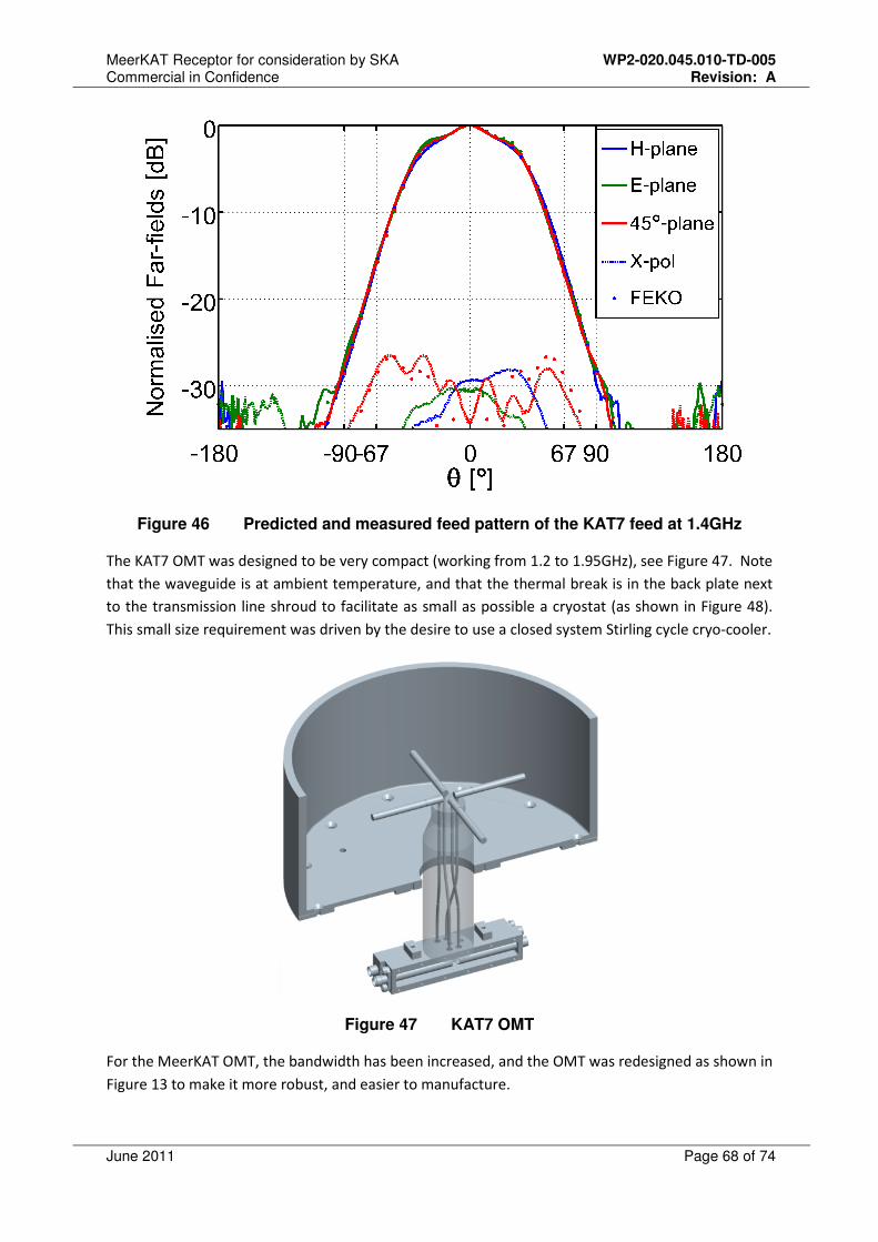
MeerKAT Receptor for consideration by SKA WP2-020.045.010-TD-005 Commercial in Confidence Revision: A
June 2011 Page 68 of 74
Figure 46 Predicted and measured feed pattern of the KAT7 feed at 1.4GHz
The KAT7 OMT was designed to be very compact (working from 1.2 to 1.95GHz), see Figure 47. Note
that the waveguide is at ambient temperature, and that the thermal break is in the back plate next
to the transmission line shroud to facilitate as small as possible a cryostat (as shown in Figure 48).
This small size requirement was driven by the desire to use a closed system Stirling cycle cryo-cooler.
Figure 47 KAT7 OMT
For the MeerKAT OMT, the bandwidth has been increased, and the OMT was redesigned as shown in
Figure 13 to make it more robust, and easier to manufacture.
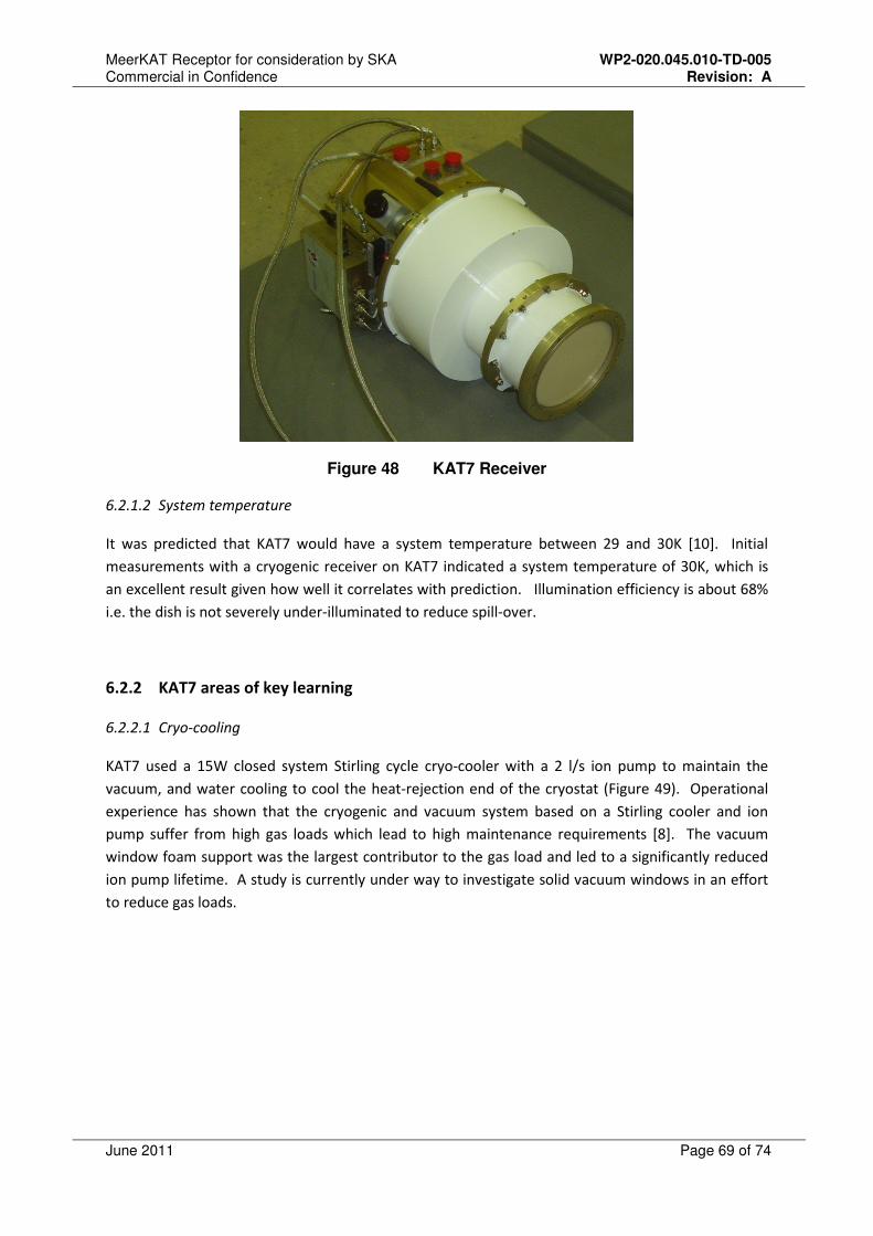
MeerKAT Receptor for consideration by SKA WP2-020.045.010-TD-005 Commercial in Confidence Revision: A
June 2011 Page 69 of 74
Figure 48 KAT7 Receiver
6.2.1.2 System temperature
It was predicted that KAT7 would have a system temperature between 29 and 30K [10]. Initial
measurements with a cryogenic receiver on KAT7 indicated a system temperature of 30K, which is
an excellent result given how well it correlates with prediction. Illumination efficiency is about 68%
i.e. the dish is not severely under-illuminated to reduce spill-over.
6.2.2 KAT7 areas of key learning
6.2.2.1 Cryo-cooling
KAT7 used a 15W closed system Stirling cycle cryo-cooler with a 2 l/s ion pump to maintain the
vacuum, and water cooling to cool the heat-rejection end of the cryostat (Figure 49). Operational
experience has shown that the cryogenic and vacuum system based on a Stirling cooler and ion
pump suffer from high gas loads which lead to high maintenance requirements [8]. The vacuum
window foam support was the largest contributor to the gas load and led to a significantly reduced
ion pump lifetime. A study is currently under way to investigate solid vacuum windows in an effort
to reduce gas loads.
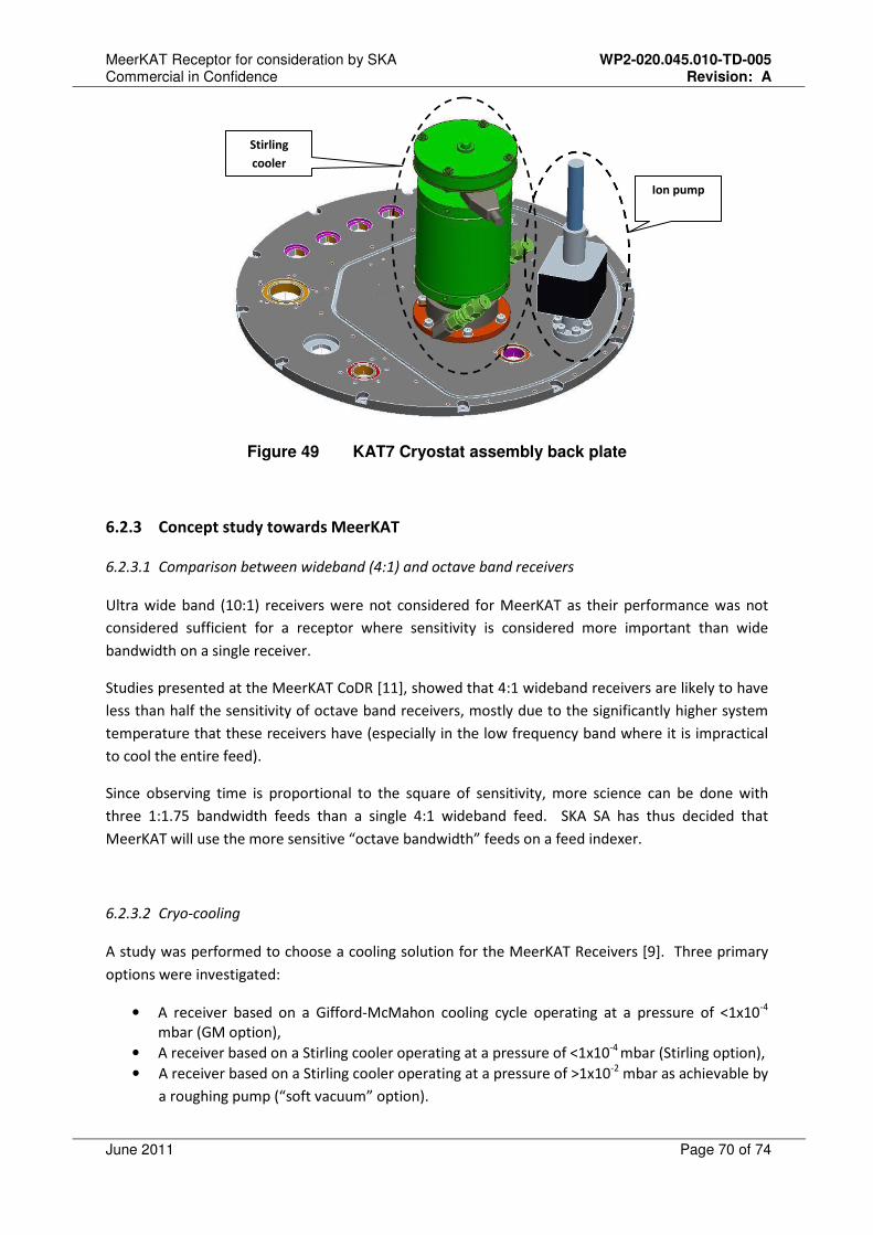
MeerKAT Receptor for consideration by SKA WP2-020.045.010-TD-005 Commercial in Confidence Revision: A
June 2011 Page 70 of 74
Figure 49 KAT7 Cryostat assembly back plate
6.2.3 Concept study towards MeerKAT
6.2.3.1 Comparison between wideband (4:1) and octave band receivers
Ultra wide band (10:1) receivers were not considered for MeerKAT as their performance was not
considered sufficient for a receptor where sensitivity is considered more important than wide
bandwidth on a single receiver.
Studies presented at the MeerKAT CoDR [11], showed that 4:1 wideband receivers are likely to have
less than half the sensitivity of octave band receivers, mostly due to the significantly higher system
temperature that these receivers have (especially in the low frequency band where it is impractical
to cool the entire feed).
Since observing time is proportional to the square of sensitivity, more science can be done with
three 1:1.75 bandwidth feeds than a single 4:1 wideband feed. SKA SA has thus decided that
MeerKAT will use the more sensitive “octave bandwidth” feeds on a feed indexer.
6.2.3.2 Cryo-cooling
A study was performed to choose a cooling solution for the MeerKAT Receivers [9]. Three primary
options were investigated:
• A receiver based on a Gifford-McMahon cooling cycle operating at a pressure of <1x10⁻⁴
mbar (GM option),
• A receiver based on a Stirling cooler operating at a pressure of <1x10⁻⁴
mbar (Stirling option),
• A receiver based on a Stirling cooler operating at a pressure of >1x10⁻²
mbar as achievable by
a roughing pump (“soft vacuum” option).
Ion pump
Stirling
cooler

MeerKAT Receptor for consideration by SKA WP2-020.045.010-TD-005 Commercial in Confidence Revision: A
June 2011 Page 71 of 74
The recommended cooling option for MeerKAT is a Gifford McMahon-based cooling solution. The
sensitivity of a receptor is directly proportional to Ae/Tsys and Tsys can be significantly reduced by
reducing the LNA noise and ohmic losses in front-end components. With a “soft vacuum” solution
the LNAs could be cooled to approximately 120K or higher, using a Stirling based cooling system the
LNAs could be cooled to approximately 70K and by using a GM-based cooling system the LNAs could
be cooled to approximately 20K. The GM based solution is approximately 21% more sensitive than
the Stirling option and 35% more sensitive than the best possible “soft vacuum” option.
For a system of three cryogenically cooled receivers, the capital cost for a GM-based solution does
not differ significantly from the capital cost for a Stirling-based cooling solution. In terms of
maintenance and operational costs, the GM-based solution is slightly more cost effective than the
Stirling solution. Although the GM solution uses more power than the Stirling solution, the Stirling
solution requires more costly maintenance [9].
6.2.3.3 Expected system temperature
The expected L-band system sensitivity is approximately 300m2/K for operating the LNAs at a
physical temperature of 20K, where they are expected to have a noise temperature of 5.5K. This is
based on a Tsys (excluding the LNA contribution) of 14K as presented in Table 7.
Aperture efficiency 66%
Tspil 4K
TCosmic backgroung 3K
TAtmosphere 2K
THorn and Dish 1K
TFoam and OMT 2K
TPost LNA RF 2K
Tsys excluding LNA 14K
Table 7 Estimated system noise excluding LNA for offset Gregorian
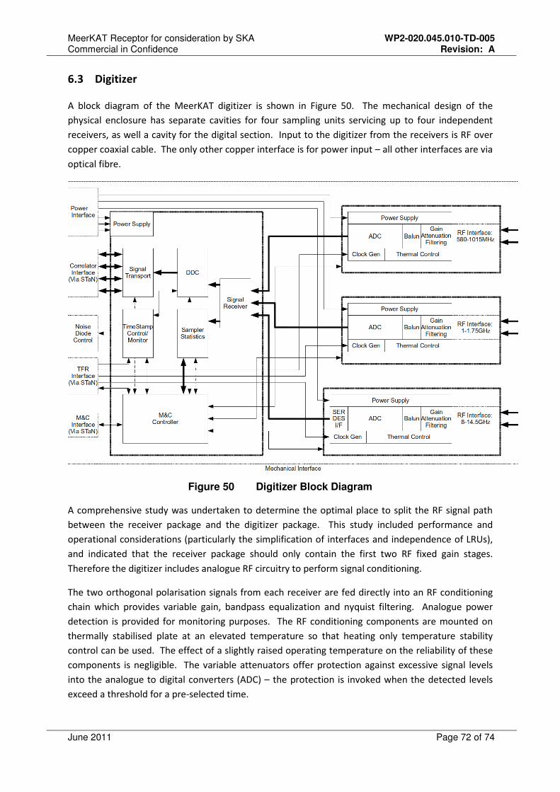
MeerKAT Receptor for consideration by SKA WP2-020.045.010-TD-005 Commercial in Confidence Revision: A
June 2011 Page 72 of 74
6.3 Digitizer
A block diagram of the MeerKAT digitizer is shown in Figure 50. The mechanical design of the
physical enclosure has separate cavities for four sampling units servicing up to four independent
receivers, as well a cavity for the digital section. Input to the digitizer from the receivers is RF over
copper coaxial cable. The only other copper interface is for power input – all other interfaces are via
optical fibre.
Figure 50 Digitizer Block Diagram
A comprehensive study was undertaken to determine the optimal place to split the RF signal path
between the receiver package and the digitizer package. This study included performance and
operational considerations (particularly the simplification of interfaces and independence of LRUs),
and indicated that the receiver package should only contain the first two RF fixed gain stages.
Therefore the digitizer includes analogue RF circuitry to perform signal conditioning.
The two orthogonal polarisation signals from each receiver are fed directly into an RF conditioning
chain which provides variable gain, bandpass equalization and nyquist filtering. Analogue power
detection is provided for monitoring purposes. The RF conditioning components are mounted on
thermally stabilised plate at an elevated temperature so that heating only temperature stability
control can be used. The effect of a slightly raised operating temperature on the reliability of these
components is negligible. The variable attenuators offer protection against excessive signal levels
into the analogue to digital converters (ADC) – the protection is invoked when the detected levels
exceed a threshold for a pre-selected time.
MeerKAT Receptor for consideration by SKA WP2-020.045.010-TD-005 Commercial in Confidence Revision: A
June 2011 Page 73 of 74
The ADC is optimised for its input frequency band and direct sampling of the RF signal is employed
for all receivers. Sampling clock generation from a reference clock input signal is performed in the
Digitizer.
Once sampled, the signals are transferred to an FPGA based digital processor. This interface will
either be parallel or SERDES, depending on the data rate requirements. The signals are digitally
down-converted to baseband prior to transmission to the Correlator. Some channelization may be
performed in the digitizer, but this is undecided at this stage.
Signal transmission is based on the SPEAD protocol and is carried via multiple commodity 10GbE
fibre links using SFP+ 10GBASE-LR modules. The possibility of using commodity 40GbE and QFP
modules is not excluded.
The Time and Frequency Reference (TFR) sub-system provides a reference clock and one pulse per
second signal at the array processor. Both of these are transmitted to the antennas and back to the
TFR in order to detect the fibre delay from the array processor to each antenna. The delay is
corrected digitally in the Correlator.
Power input to the digitizer is 220V 50Hz AC, allowing effective EMC filtering at the boundary of the
enclosure. Control and monitoring is performed via a 1GbE interface and is based on the KATCP
protocol.
This sub-system is applicable to SKA phase 1 with minor modifications for changes in the pass-band
frequencies. It is well matched to a CASPER correlator.
7 Cost Estimates
Costing detail cannot be presented at this stage due to the sensitive commercial phase of the
MeerKAT project (high-value tenders are to be released in the next 6 months). In a year or two it
will be feasible to present detailed costing models for the MeerKAT receptor.
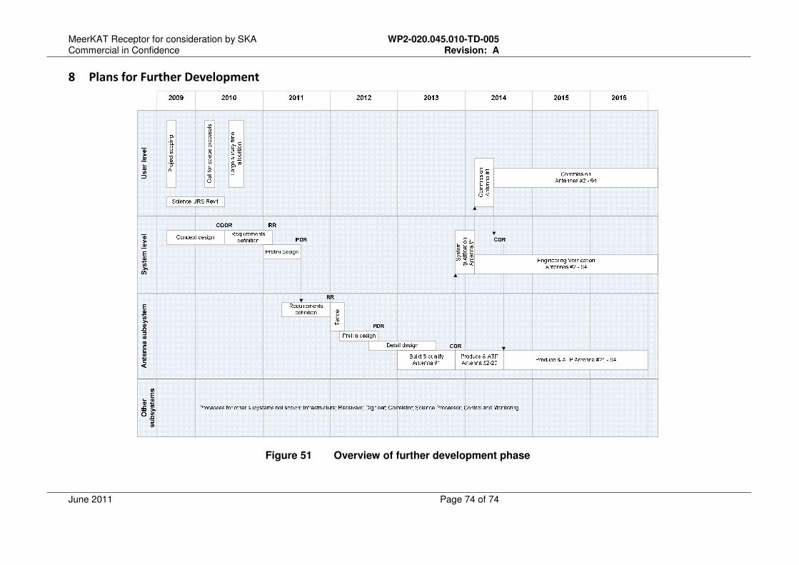
MeerKAT Receptor for consideration by SKA WP2-020.045.010-TD-005 Commercial in Confidence Revision: A
June 2011 Page 74 of 74
8 Plans for Further Development
Figure 51 Overview of further development phase