contents · ve effective core volume mm 3 acp cross-sectional center leg/pole area, mm2 acp min....
TRANSCRIPT

1
CONTENTS
Introduction .............................................................................. 3TDK Ferrite Cores in Switching Power Supplies...................... 4Selected Items of Legend ........................................................ 5Material Characteristics ........................................................... 6
PART I E Cores ................................................................................... 21EI Cores................................................................................... 22EE and EF Cores..................................................................... 24EE and EI Bobbins................................................................... 28EER Cores............................................................................... 32EER Bobbins ........................................................................... 34ETD and EC Cores .................................................................. 36ETD and EC Bobbins............................................................... 38Original TDK Cores................................................................ 41PQ Cores ................................................................................. 42PQ Bobbins.............................................................................. 44LP Cores and Bobbins............................................................. 46EPC Cores............................................................................... 48EPC Bobbins and Accessories ................................................ 50EP Cores and Bobbins ............................................................ 52RM Cores ................................................................................ 55RM Cores................................................................................. 56RM Bobbins ............................................................................. 58SMD Cores.............................................................................. 61SMD Cores and Bobbins ......................................................... 62ET, UU and FT Cores ............................................................. 65ET and UU cores ..................................................................... 66FT Cores.................................................................................. 67T Cores ................................................................................... 69Toroidal Cores (For Common Mode Choke)............................ 70Toroidal Cores (For General Use) ........................................... 72
PART II Technical Data ....................................................................... 77EI Cores................................................................................... 78EE Cores ................................................................................. 91EER Cores............................................................................... 101ETD Cores ............................................................................... 108PQ Cores ................................................................................. 115LP Cores.................................................................................. 124RM Cores................................................................................. 127EPC Cores............................................................................... 134Maximum Number of Turns on Bobbins.............................. 143Wire Table ............................................................................... 147
The information included in this book is subject to change without notice resulting from technical developments and product improvements.
Specifications which provide more details for the proper and safe use of the described product are available upon request.


3
Introduction
Since its outset in 1935, in the wake of the invention of ferrite, TDK has aimed to develop its world leading electronic technology in both material development and production. This accumulated expertise in fine structural control technology has resulted in high performance ferrite components. These components have recently been in greater demand for electronic equipment requiring reduction in size and weight.
TDK Ferrite Division engineers have successfully explored every avenue of high performance ferrites, aiming to produce self-contained energy sources for microelectronic equipment.To this end, TDK has developed high frequency power ferrite, such as PC33,PC40,PC44,PC45,PC46,PC47 and PC50 that are identifiable by their excellent magnetic characteristics. It is these high reliability ferrite components that have largely contributed to reducing the size of switching power supplies and DC to DC Converters for micro-electronic equipment.
Other TDK endeavors deserving mention are ferrite for EMI filters and common mode chokes with excellent frequency characteristics. Not only have TDK’s researchers overcome the theoretical limiting value of the high µ material’s operating fre-quency, but they have also succeeded in developing a new material HS72 and HS10 those are characterized by its high impedance at high frequencies.
In order for you to take full advantage of these and other materials shown in this booklet, TDK has developed a range of cores and accessories to meet the need for miniature high per-formance switching power supplies and DC to DC Converters. TDK offers a comprehensive range of materials and core shapes to meet all of your power requirements.

4
TDK Ferrite Cores in Switching Power Supplies(Single forward converter)
Notes: • LP and EPC cores are ideal for use in thin transformers.• LP cores are available in .5 and .7 inches in height (when mounted).• EP cores are available in .5 and .65 inches in height (when mounted).
Current transformer
Common mode choke coil Main power transformerActive filer choke coil Smoothing choke coil
Auxiliary power transformer Drive Transformer
EMI/RFI filter PFC Active filterOutput rectifier
smoothing circuit
Auxiliary powercircuit
Power switchcircuit Control circuit
DC outputAC input
5
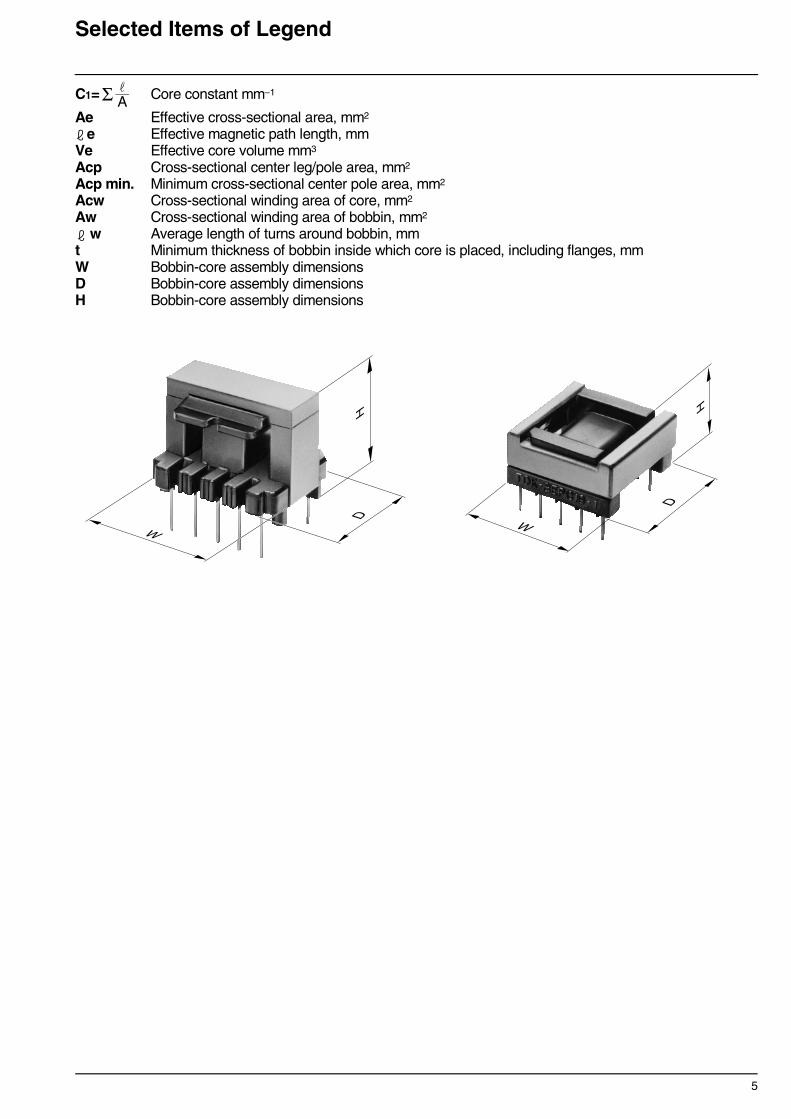
Selected Items of Legend
C1= Core constant mm–1
Ae Effective cross-sectional area, mm2
e Effective magnetic path length, mmVe Effective core volume mm3
Acp Cross-sectional center leg/pole area, mm2
Acp min. Minimum cross-sectional center pole area, mm2
Acw Cross-sectional winding area of core, mm2
Aw Cross-sectional winding area of bobbin, mm2
w Average length of turns around bobbin, mmt Minimum thickness of bobbin inside which core is placed, including flanges, mmW Bobbin-core assembly dimensions D Bobbin-core assembly dimensions H Bobbin-core assembly dimensions
Σ A
H
WD
H
W
D

6
Material CharacteristicsTable 1
MATERIAL CHARACTERISTICS(for Transformer and Choke)
∗ Average value∗∗ 500kHz, 50mT
∗ Average value
Material PC40 PC44 PC47 PC50Initial permeability µi 2300±25% 2400±25% 2500±25% 1400±25% Amplitude permeability µa 3000 min. 3000 min.
Core loss volume density(Core loss)∗
[B=200mT]Pcv kW/m3
25kHzsine wave
25°C 12060°C 80100°C 70120°C 85
100kHzsine wave
25°C 600 600 600 130∗∗
60°C 450 400 400 80∗∗
100°C 410 300 250 80∗∗
120°C 500 380 360 110∗∗
Saturation magnetic flux density∗
[H=1194A/m]Bs mT
25°C 510 510 530 470 60°C 450 450 480 440100°C 390 390 420 380120°C 350 350 390 350
Remanent flux density∗ Br mT
25°C 95 110 180 140 60°C 65 70 100 110100°C 55 60 60 98120°C 50 55 60 100
Coercive force∗ Hc A/m
25°C 14.3 13 13 36.5 60°C 10.3 9 9 31.0100°C 8.8 6.5 6 27.2120°C 8 6 7 26.0
Curie temperature Tc °C >215 >215 >230 >240Density∗ db kg/m3 4.8×10³ 4.8×10³ 4.9×10³ 4.8×10³
Electrical resistivity∗ ρv Ω • m 6.5 6.5 4.0 30
Material PC45 PC46 PC33Initial permeability µi 2500±25% 3200±25% 1400±25% Amplitude permeability µa
Core loss volume density(Core loss)∗
[B=200mT]Pcv kW/m3
25kHzsine wave
25°C60°C100°C120°C
100kHzsine wave
25°C 570 350 110060°C 250(75°C) 250(45°C) 800100°C 460 660 600120°C 650 760 680
Saturation magnetic flux density∗
[H=1194A/m]Bs mT
25°C 530 520 520 60°C 480 470 490100°C 420 410 440120°C 390 380 420
Remanent flux density∗ Br mT
25°C 120 80 220 60°C 80 80 150100°C 80 130 100120°C 110 140 100
Coercive force∗ Hc A/m
25°C 12 10 23 60°C 9 9 17100°C 8 10 14120°C 9 9 14
Curie temperature Tc °C >230 >230 >290Density∗ db kg/m3 4.8 4.8 4.8Electrical resistivity∗ ρv Ω • m 3.0 3.0 2.5

7
Material CharacteristicsTable 2
MATERIAL CHARACTERISTICS(for Common mode Choke)
∗ Average value
MATERIAL CHARACTERISTICS(for Telecommunication)
∗ Average value
∗ Average value
Material HS52 HS72 HS10
Initial permeability µi 5500±25%7500±25%(2000min. at 500kHz)
10000±25%
Relative loss factor∗ tanδ/µi ×10–6 10(100kHz) 30(100kHz) 30(100kHz)Saturation magnetic flux density∗ [H=1194A/m]
Bs mT 25°C 410 410 380
Remanent flux density∗ Br mT 25°C 70 80 120Coercive force∗ Hc A/m 25°C 6 6 5Curie temperature Tc °C >130 >130 >120Density∗ db kg/m3 4.9×10³ 4.9×10³ 4.9×10³ Electrical resistivity∗ ρv Ω • m 1 0.2 0.2
Material H5A H5B2 H5C2 H5C3
Initial permeability µi 3300 7500±25% 10000±30% 15000±30%
Relative loss factor tanδ/µi ×10–6 <2.5(10kHz)<10(100kHz)
<6.5(10kHz) <7.0(10kHz) <7.0(10kHz)
Temperature factor of initial permeability
αµir ×10–6
–30 to +20°C0 to 20°C20 to 70°C
–0.5 to 2.0
–0.5 to 2.0
0 to 1.8
0 to 1.8
–0.5 to 1.5
–0.5 to 1.5
–0.5 to 1.5
–0.5 to 1.5Saturation magnetic flux density∗ [H=1194A/m]
Bs mT 25°C 410 420 400 360
Remanent flux density∗ Br mT 25°C 100 40 90 105Coercive force∗ Hc A/m 25°C 8.0 5.6 7.2 4.4 Curie temperature Tc °C >130 >130 >120 >105
Hysteresis material constant ηB <0.8 <1.0 <1.4 <0.5
Disaccommodation factor DF ×10–6 <3 <3 <2 <2 Density∗ db kg/m3 4.8×10³ 4.9×10³ 4.9×10³ 4.95×10³
Electrical resistivity∗ ρv Ω • m 1 0.1 0.15 0.15
Material HP5 DN40 DN70
Initial permeability µi 5000±20% 4000±25% 7500±25%
Relative loss factor tanδ/µi ×10–6 <3.5(10kHz) <2.5(10kHz) <2.0(10kHz)
Temperature factor of initial permeability
αµir ×10–6
–30 to +20°C0 to 20°C20 to 70°C
±12.5%±12.5%
–0.5 to 2.0
–0.5 to 2.0
–0.5 to 1.5
–0.5 to 1.5Saturation magnetic flux density∗ [H=1194A/m]
Bs mT 25°C 400 405 390
Remanent flux density∗ Br mT 25°C 65 95 45Coercive force∗ Hc A/m 25°C 7.2 8.0 3.5Curie temperature Tc °C >140 >130 >105
Hysteresis material constant ηB <0.4 <0.8 <0.2
Disaccommodation factor DF ×10–6 <3 <3 <2.5 Density∗ db kg/m3 4.8×10³ 4.8×10³ 5.0×10³
Electrical resistivity∗ ρv Ω • m 0.15 1.0 0.3
+40%–0%
10–6
mT
10–6
mT

8
Material Characteristics
µi vs. frequency Characteristics tanδ/µi vs. frequency Characteristics
Magnetization Curves (Typical)Material: PC40 Material: PC44
Material: PC50
105
104
103
102
µi
Frequency(kHz)1 102 10310 104
H5C3HS10HS72
HS52PC44
PC40
PC50
10–3
10–4
10–5
10–6
tan
δ/µi
Frequency(kHz)1 102 10310 104
PC50H5C3
HS10HS72
HS52
PC40PC44
0
100
200
300
400
500
Flu
x de
nsity
B( m
T)
Magnetic field H(A/m)0 800 1600
25˚C
60˚C
100˚C
120˚C
0
100
200
300
400
500
Flu
x de
nsity
B( m
T)
Magnetic field H(A/m)0 800 1600
25˚C
60˚C
100˚C
120˚C
0
100
200
300
400
500
Flu
x de
nsity
B( m
T)
Magnetic field H(A/m)0 800 1600
25˚C60˚C80˚C
100˚C120˚C

9
Core loss (Typical)Material: PC40 Material: PC44
Material: PC50
105
104
103
102
101
100
Cor
e lo
ss P
cv( k
W/m
3 )
Flux density B(mT)50 200 300100 500
500kHz
300kHz
200kHz
100kHz
50kHz
25kHz
(Sine wave data)
60˚C100˚C
Test core: EI30
105
104
103
102
101
100
Cor
e lo
ss P
cv( k
W/m
3 )
Flux density B(mT)50 200 300100 500
500kHz
300kHz
200kHz
100kHz
50kHz
25kHz
(Sine wave data)
60˚C100˚C
Test core: T31×8×19
(Sine wave data)
1MHz
300kHz
700kHz
200kHz
500kHz
100
101
102
103
104
105
1 10 100 1000Flux density Bm(mT)
Cor
e lo
ss P
cv( k
W/m
3 )
60˚C100˚C
Test core: T20X5X10
10
Material Characteristics
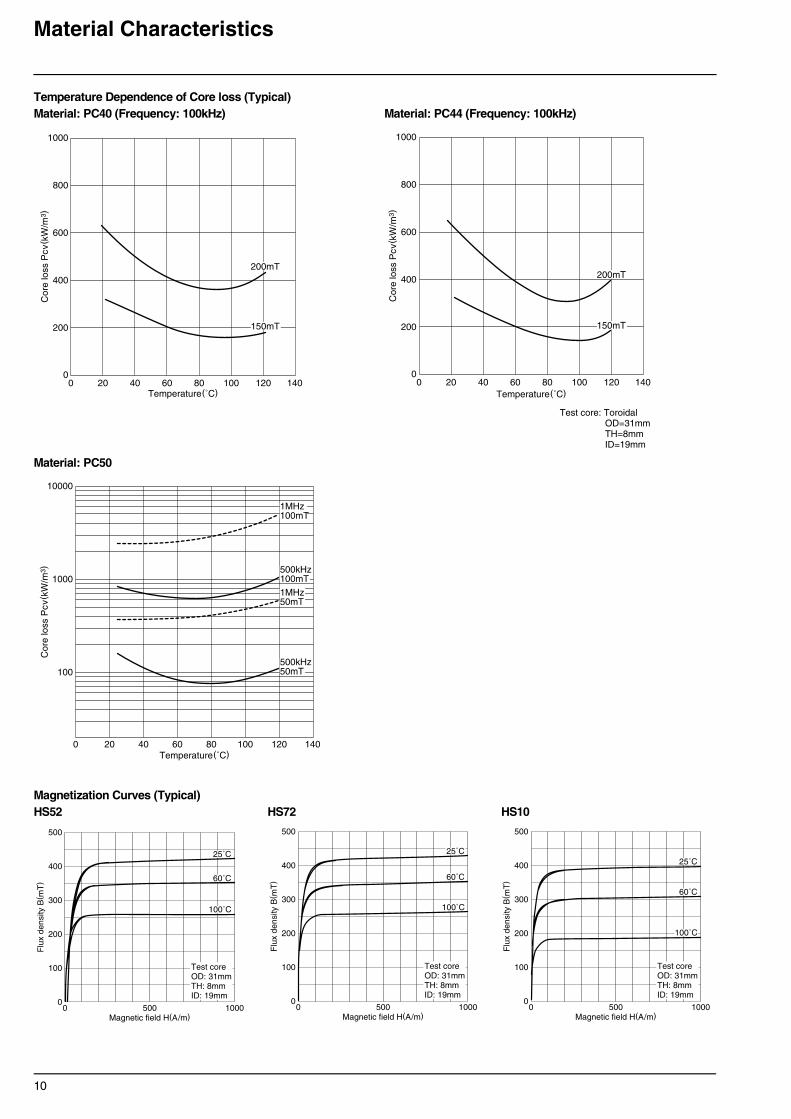
Temperature Dependence of Core loss (Typical)Material: PC40 (Frequency: 100kHz) Material: PC44 (Frequency: 100kHz)
Material: PC50
Magnetization Curves (Typical)HS52 HS72 HS10
0
200
400
600
800
1000
Cor
e lo
ss P
cv( k
W/m
3 )
Temperature(˚C)0 20 40 60 80 100 120 140
200mT
150mT
0
200
400
600
800
1000
Cor
e lo
ss P
cv( k
W/m
3 )Temperature(˚C)
0 20 40 60 80 100 120 140
Test core: ToroidalOD=31mmTH=8mmID=19mm
200mT
150mT
10000
1000
100
Cor
e lo
ss P
cv( k
W/m
3 )
Temperature(˚C)0 20 40 60 80 100 120 140
1MHz100mT
500kHz100mT
1MHz50mT
500kHz50mT
0
100
200
300
400
500
Flu
x de
nsity
B( m
T)
Magnetic field H(A/m)0 500 1000
25˚C
60˚C
100˚C
Test coreOD: 31mmTH: 8mmID: 19mm
0
100
200
300
400
500
Flu
x de
nsity
B( m
T)
Magnetic field H(A/m)0 500 1000
25˚C
60˚C
100˚C
Test coreOD: 31mmTH: 8mmID: 19mm
0
100
200
300
400
500
Flu
x de
nsity
B( m
T)
Magnetic field H(A/m)0 500 1000
25˚C
60˚C
100˚C
Test coreOD: 31mmTH: 8mmID: 19mm
11
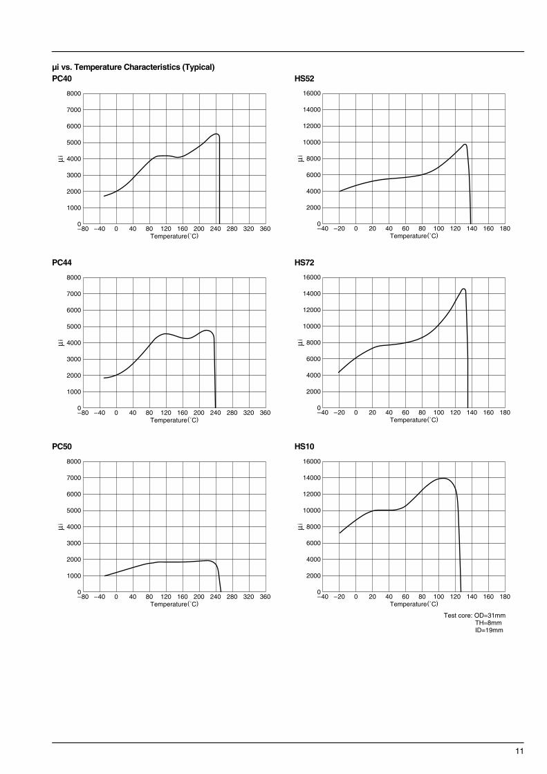
µi vs. Temperature Characteristics (Typical)PC40 HS52
PC44 HS72
PC50 HS10
0
1000
2000
3000
4000
5000
6000
7000
8000
µi
Temperature(˚C)–80 –40 0 40 80 120 160 200 240 280 320 360
0
2000
4000
6000
8000
10000
12000
14000
16000
µi
Temperature(˚C)–40 –20 0 20 40 60 80 100 120 140 160 180
0
1000
2000
3000
4000
5000
6000
7000
8000
µi
Temperature(˚C)–80 –40 0 40 80 120 160 200 240 280 320 360
0
2000
4000
6000
8000
10000
12000
14000
16000
µi
Temperature(˚C)–40 –20 0 20 40 60 80 100 120 140 160 180
0
1000
2000
3000
4000
5000
6000
7000
8000
µi
Temperature(˚C)–80 –40 0 40 80 120 160 200 240 280 320 360
0
2000
4000
6000
8000
10000
12000
14000
16000
µi
Temperature(˚C)–40 –20 0 20 40 60 80 100 120 140 160 180
Test core: OD=31mmTH=8mmID=19mm

12
Low Loss Ferrite Material PC47for Power Supply
PC47 has the best properties for transformers of power supplies, adapters and chargers.The core loss and saturation magnetic flux density of PC47 are far better than PC44 and PC40 which are currently in use.
FEATURES• Core loss: 250kW/m3 at 100kHz, 200mT, 100°C.• Low core loss at wide frequency range 100kHz to 300kHz.• Higher saturation flux density than PC44.
APPLICATIONS• Switching power supplies• Adapters and chargers for notebook type pc• CCFL LCD backlight
MATERIAL CHARACTERISTICS
Pcv TEMPERATURE DEPENDENCE CHARACTERISTICS (Typical)
Bs and Br TEMPERATURE DEPENDENCE CHARACTERISTICS (Typical)
Material PC47(NEW) PC44 PC40Initial permeability µi 25°C 2500±25% 2400±25% 2300±25%
Core loss volume density[100kHz, 200mT]
Pcv kW/m3
25°C 600 600 60060°C 400 400 450100°C 250 300 410
Saturation magnetic flux density [1000A/m]
Bs mT25°C 530 510 510100°C 420 390 390
Remanent flux density Br mT25°C 180 110 95100°C 60 60 55
Curie temperature Tc °C min. 230 215 215 Density db kg/m3 4.9×10³ 4.8×10³ 4.8×10³
00 20 40 60 80 0100 120 140
100
200
300
400
500
600
700
800
900
1000
Temperature(˚C)
Cor
e lo
ss P
cv( k
W/m
3 )
100kHz/200mT
PC40
PC44PC47
0
500
1000
1500
2000
2500
3000
3500
4000
4500
5000
5500
0 20 40 60 80 0100 120 140
6000
Temperature(˚C)
Cor
e lo
ss P
cv( k
W/m
3 )
PC40
PC44PC47
200kHz/300mT
0
100
200
300
400
500
600
0 20 40 60 80 100 120 140 160Temperature(˚C)
Bs,
Br(
mT
) PC47PC44PC40
PC47PC44PC40
Bs
Br
13
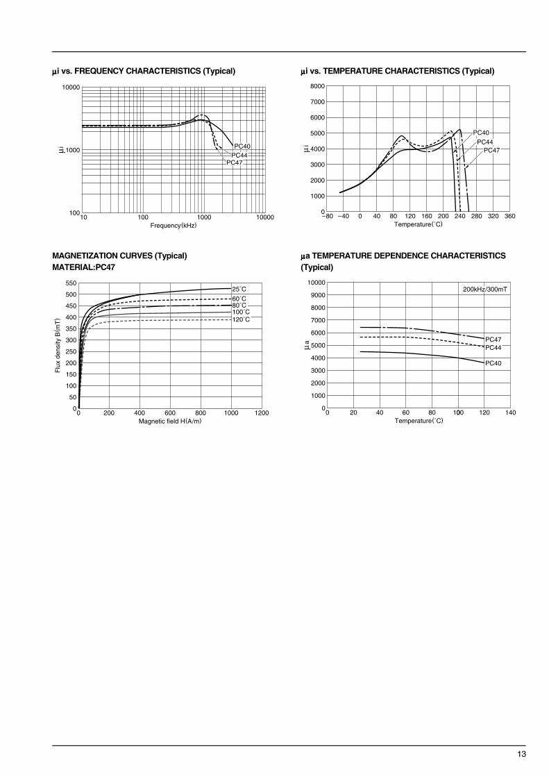
µµµµi vs. FREQUENCY CHARACTERISTICS (Typical) µµµµi vs. TEMPERATURE CHARACTERISTICS (Typical)
MAGNETIZATION CURVES (Typical) µµµµa TEMPERATURE DEPENDENCE CHARACTERISTICS MATERIAL:PC47 (Typical)
100
1000
10000
10 100 1000 10000Frequency(kHz)
µi PC40PC44
PC47
0
1000
2000
3000
4000
5000
6000
7000
8000
–80 –40 0 40 80 120 160 200 240 280 320 360Temperature(˚C)
µi
PC40
PC44PC47
0
50
100
150
200
250
300
350
400
450
500
550
0 200 400 600 800 1000 1200Magnetic field H(A/m)
Flu
x de
nsity
B( m
T)
25˚C
60˚C80˚C100˚C120˚C
0
1000
2000
3000
4000
5000
6000
7000
8000
9000
0 20 40 60 80 0100 120 140
10000
Temperature(˚C)
µa
PC40
PC44PC47
200kHz/300mT

14
Low Loss Ferrite Materials PC45 and PC46for Power Supply
In recent years, with the advent of notebook type pc, VCR’s, digital camera’s and mobile communication devices, technological demands have risen for higher performance CCFL LCD backlight units that have smaller sizes, lower profiles and higher efficiency.The PC45 and PC46 are materials developed to achieve higher efficiency in designing minimize core loss at practical temperature ranges (PC45: 60 to 80°C and PC46: 40 to 50°C) and high saturation flux density.They are also suitable for the transformers of DC to DC converters and adapters of notebook type pc.
APPLICATIONS• Switching power supplies• Adapters and chargers for notebook type pc• CCFL LCD backlight
MATERIAL CHARACTERISTICS
Pcv TEMPERATURE DEPENDENCE CHARACTERISTICS Bs and Br TEMPERATURE DEPENDENCE (Typical) CHARACTERISTICS (Typical)
µµµµi vs. FREQUENCY CHARACTERISTICS (Typical) µµµµi vs. TEMPERATURE CHARACTERISTICS (Typical)
Material PC45(NEW) PC46(NEW) PC44Initial permeability µi 25°C 2500±25% 3200±25% 2400±25%
Core loss volume density[100kHz, 200mT]
Pcv kW/m3
25°C 570 350 60060°C 250(75°C) 250(45°C) 400100°C 460 660 300
Saturation magnetic flux density [1000A/m]
Bs mT25°C 530 530 510100°C 420 410 390
Remanent flux density Br mT25°C 120 80 110100°C 80 115 60
Curie temperature Tc °C min. 230 230 215 Density db kg/m3 4.8×10³ 4.8×10³ 4.8×10³
00 20 40 60 80 0100 120 140
100
200
300
400
500
600
700
800
900
1000
Temperature(˚C)
Cor
e lo
ss P
cv( k
W/m
3 )
PC44
PC45
PC46
100kHz/200mT
0
100
200
300
400
500
600
0 20 40 60 80 100 120 140 160Temperature(˚C)
Bs,
Br(
mT
) PC45PC46PC44
PC46PC45PC44
Bs
Br
100
1000
10000
10 100 1000 10000Frequency(kHz)
µi
PC46
PC45PC44
0
1000
2000
3000
4000
5000
6000
7000
8000
–80 –40 0 40 80 120 160 200 240 280 320 360Temperature(˚C)
µi
PC44
PC45
PC46

15
MAGNETIZATION CURVESMATERIAL:PC45 MATERIAL:PC46
0
50
100
150
200
250
300
350
400
450
500
550
0 200 400 600 800 1000 1200Magnetic field H(A/m)
Flu
x de
nsity
B( m
T)
25˚C
60˚C80˚C100˚C120˚C
0
50
100
150
200
250
300
350
400
450
500
550
0 200 400 600 800 1000 1200Magnetic field H(A/m)
Flu
x de
nsity
B( m
T)
25˚C
60˚C80˚C100˚C120˚C

16
High Saturation Flux Density Material PC33for Choke Coil
PC33 has the best properties for smoothing choke coil of power supplies.The saturation magnetic flux density of PC33 is far better than PC44 and PC40 which are currently in use.
FEATURES• Higher saturation flux density than PC44 and PC40.• Most suitable ferrite material for choke coils.• Maintain high saturation magnetic flux density at high temperature.
APPLICATIONS• Power choke coils for switching power supplies• Power choke coils for notebook type pc
MATERIAL CHARACTERISTICS
Pcv TEMPERATURE DEPENDENCE CHARACTERISTICS Bs TEMPERATURE DEPENDENCE CHARACTERISTICS(Typical) (Typical)
Material PC33(NEW) PC44 PC40Saturation magnetic flux density [1000A/m]
Bs mT25°C 510 510 510100°C 440 390 390
Initial permeability µi 25°C 1400±25% 2400±25% 2300±25%
Core loss volume density[100kHz, 200mT]
Pcv kW/m3
25°C 1100 600 60060°C 800 400 450100°C 600 300 410
Curie temperature Tc °C min. 290 215 215 Density db kg/m3 4.8×10³ 4.8×10³ 4.8×10³
0100200300400500600700800900
100011001200130014001500
0 20 40 60 80 0100 120 140Temperature(˚C)
Cor
e lo
ss P
cv( k
W/m
3 )
PC40PC44
PC33
100kHz/200mT
0
100
200
300
400
500
600
0 20 40 60 80 100 120 140 160Temperature(˚C)
Bs(
mT
)
PC33
PC44PC40

17
Low THD Materials DN40 and DN70for xDSL Modem Transformers
The use of xDSL technique becomes wide spread as a high broad-band access to the internet. In order to utilize such network access as sufficient as possible, low THD (Total Harmonic Distortion) of transformer for xDSL modem is quite important to transfer the significant signals.Materials DN40 and DN70, TDK achieved such requirements recently, are developed to meet low THD over a wide temperature range(0 to 85°C) and wide frequency range( 5kHz).Therefore, They are suitable for the high performance transformer design for xDSL modem applications.Standardization of AL-value will help you to select the optimum core at the transformer design.
FEATURES• Meet low THD over a wide temperature range(0 to 85°C) and
wide frequency range ( 5kHz).
APPLICATIONS• Transformer for xDSL modem
APPLIED CORE TYPE AND AL-value
MATERIAL CHARACTERISTICS
• Unless otherwise specify the tolerance, the values are shown as a typical.
THD TEMPERATURE DEPENDENCE CHARACTERISTICS (Typical) µµµµi vs. TEMPERATURE CHARACTERISTICS (Typical)
Core Type AL-valueEP EP7 40, 63, 100, 160, 250
EP10 40, 63, 100, 160, 250EP13 63, 100, 160, 250, 400, 500
Material DN70(NEW) DN40Initial permeability µi 25°C 7500±25% 4000±25% Relative loss factor [10kHz] tanδ/µi ×10–6 25°C <2.0 <2.5
Temperature factor of intial permeability αµir–30 to +20°C20 to 70°C
–0.5 to +1.5–0.5 to +1.5
–0.5 to 2.0–0.5 to 2.0
Saturation magnetic flux density [1000A/m]
Bs mT 25°C 390 405
Hysteresis material constant[25°C, 1.5 to 3.0mT, 10kMz]
ηB <0.2 <0.8
Curie temperature Tc °C min. 105 130Density db kg/m3 5.0×10³ 4.8×10³ Electrical resistivity ρv Ω • m 0.3 1.0
10–6
mT
–70
–75
–80
–85
–90
–40 –20 0 20 40 60 80 100Temperature(˚C)
TH
D( d
B)
DN70
DN40
EP7AP-Sys2@45mT, 5kHz
0
5000
10000
15000
20000
25000
–40 160140120100806040200–20Temperature(˚C)
µi
DN70
DN40


Part I


21
E Cores
CoresEI12.5 to EI60EE8 to EE62.3/62/6EF12.6 to EF32EER25.5 to EER49ETD19 to ETD49EC70 to EC120
BobbinsBE8 to BE62.3BEER25.5 to BEER49BETD19 to BETD24BEC70 to BEC90
Accessories
OrderingCodeSystem
Cores
Bobbins
Accessories
PC40 EI 30 – ZMaterialSize of E core
AL-value Z: without air gapG : with air gap
B E30 – 1110 CPFRSymbol of BobbinSize of E coreCode of Bobbin Material
Type of Terminal PinNumber of Terminal Pin
Number of Section
F E – 30 – FSymbol of Accessory Type of Accessory
Size of E core

22
∗ Please see the next page additionally.
EI Cores
Part No. JISDimensions in
A B C D E F Hmin.
PC40EI12.5-Z JIS FEI 12.5
12.4±0.3 .488±.012
7.4±0.1 .291±.004
4.85±0.15.191±.006
2.4±0.1 .094±.004
8.8.346
5.1±0.1 .201±.004
1.6.063
PC40EI16-Z JIS FEI 16
16.0±0.3 .630±.012
12.2±0.2 .480±.008
4.8±0.2 .189±.008
4.0±0.2 .157±.008
11.6.457
10.2±0.2 .402±.008
2.05.081
PC40EI19-Z20.0±0.3 .787±.012
13.55±0.25.533±.010
5.0±0.2 .197±.008
4.55±0.15.179±.006
14.3.563
11.15±0.15.439±.006
2.75.108
PC40EI22-Z22.0±0.3 .866±.012
14.55±0.25.573±.010
5.75±0.25.226±.010
5.75±0.25.226±.010
13.0.512
10.55±0.25.415±.010
4.5.177
PC40EI22/19/6-Z JIS FEI 22
22.0±0.4 .866±.016
14.7±0.2 .579±.008
5.75±0.25.226±.010
5.75±0.25.226±.010
15.75.620
10.7±0.2 .421±.008
3.0.118
PC40EI25-Z25.3±0.5 .996±.020
15.55±0.25.612±.010
6.75±0.25.266±.010
6.5±0.3 .256±.012
19.0.748
12.35±0.25.486±.010
3.0.118
PC40EI28-ZJIS FEI 28
28.0
1.10216.75±0.25.659±.010
10.6±0.2.417±.008 7.2±0.3
.283±.01218.4.724
12.25±0.25.482±.010
4.5.17710.7±0.3
.421±.012
PC40EI30-Z JIS FEI 30
30.0
1.18121.25±0.25.837±.010
10.7±0.3 .421±.012
10.7±0.3 .421±0.12
19.7.776
16.25±0.25.640±.010
5.0.197
PC40EI33/29/13-Z33.0
1.29923.75±0.25.935±.010
12.7±0.3 .500±.012
9.7±0.3 .382±.012
23.4.921
19.25±0.25.758±.010
4.45.175
PC40EI35-ZJIS FEI 35
35.0±0.5 1.378±.020
24.35±0.15.959±.006
10.0±0.3 .394±.012
10.0±0.3 .394±.012
24.5.965
18.25±0.15.719±.006
5.0.197
PC40EI40-ZJIS FEI 40
40.0±0.5 1.575±.020
27.25±0.251.073±.010
11.65±0.35.459±.014
11.65±0.35.459±.014
27.21.071
20.25±0.25.797±.010
6.2.244
PC40EI50-Z JIS FEI 50
50.0
1.96933.35±0.351.313±.014
14.6±0.4 .575±.016
14.6±0.4 .575±.016
33.51.319
24.75±0.25.974±.010
7.7.303
PC40EI60-Z JIS FEI 60
60.0
2.36235.85±0.351.411±.014
15.6±0.4 .614±.016
15.6±0.4 .614±.016
43.61.717
27.85±0.351.096±.014
7.7.303
B
CF
EH
H
D A
C
A
I
mminches
+0.7–0.5
+.028–.020
(E core)
(I core)
+0.7–0.4
+.028–.016
+0.8–0.5
+.031–.020
+1.2–0.7
+.047–.028
+1.4–0.8
+.055–.031

23
∗ P
leas
e se
e th
e fo
rmer
pag
e ad
ditio
nally
.
∗ AL-value: 1kHz, 0.5mA, 100Ts
Effective parameter Electrical characteristicsWt(g)
Bobbin itemI C1
(mm–1)Ae(mm2)
e(mm)
Ve(mm3)
AL-value (nH/N2)∗ Core loss (W) max.Without air gap With air gap 100kHz, 200mT, 100°C
1.5±0.1.059±.004
1.48 14.4 21.3 308 1200±25% 63±7%100±10%
0.12 1.9 BE12.5-1110CPFR
2.0±0.2.079±.008
1.75 19.8 34.6 685 1100±25% 80±7%160±10%
0.31 3.3BE16-116CPFRBE16-118CPHFRBE16-1110CPNFR
2.3±0.1.091±.004
1.65 24.0 39.6 950 1400±25% 80±7%160±10%
0.42 5.1BE19-116CPFRBE19-118CPHFRBE-19-5116
4.5±0.2.177±.008
0.936 42.0 39.3 1650 2400±25% 125±7%250±10%
0.6 9.8BE22-1110CPFRBE22-118CPFRBE-22-5116
4.0±0.2.157±.008
1.13 37.0 41.8 1550 2000±25% 125±7%250±10%
0.64 8.5 BE22/19/6-118CPFR
2.7±0.2.106±.008
1.15 41.0 47.0 1930 2140±25% 125±7%250±10%
0.79 9.8BE25-118CPFRBE-25-5116
3.5±0.3.138±.012
0.57 86.0 48.2 4150 4300±25% 200±5%400±7%
1.65 22 BE28-1110CPLFR
5.5±0.2.217±.008
0.522 111 58.0 6440 4690±25% 200±5%400±7%
3.1 34BE30-1110CPFRBE30-1112CPFRBE-30-5112
5.0±0.3.197±.012
0.567 119 67.5 8030 4400±25% 200±5%400±7%
3.5 41 BE33-1112CPLFR
4.6±0.3.181±.012
0.664 101 67.1 6780 3800±25% 200±5%400±7%
2.85 36 BE35-1112CPLFR
7.5±0.3 .295±.012
0.520 148 77.0 11400 4860±25% 200±5%400±7%
4.8 60BE40-1112CPFRBE40-1112CPNFRBE-40-5112
9.0±0.3.354±.012
0.409 230 94.0 21620 6110±25% 250±5%500±7%
9.2 115BE50-1112CPFRBE-50-5112
8.5±0.3.335±.012
0.441 247 109 26900 5670±25% 250±5%500±7%
12.5 139BE60-1112CPFRBE-60-5112

24
∗ Please see the next page additionally.
EE and EF Cores
Part No.U.S. Iam. cores,DIN standardJIS
TypeDimensions in
A B C D E F Hmin.
PC40EE8-Z JIS FEE 8.3
18.3±0.2 .327±.008
4.0±0.1 .157±.004
3.6±0.2 .142±.008
1.85±0.15.073±.006
6.0.236
3.0±0.1 .118±.004
1.0.039
PC40EE10/11-Z JIS FEE 10.2
110.2±0.2 .402±.008
5.5±0.1 .217±.004
4.75±0.15.187±.006
2.45±0.15.096±.006
7.7.303
4.20±0.15.165±.006
1.1.043
PC40EF12.6-ZDIN 41985
112.7±0.4 .500±.016
6.4±0.1 .252±.004
3.6±0.2 .142±.008
3.65±0.15.144±.006
8.8.346
4.65±0.15.183±.006
1.83.072
PC40EE13-Z 113.0±0.2 .512±.008
6.00±0.15.236±.006
6.15±0.15.242±.006
2.75±0.15.108±.006
10.0.394
4.6±0.1 .181±.004
1.4.055
PC40EE16-Z JIS FEE 16A
116.0±0.3 .630±.012
7.15±0.15.281±.006
4.8±0.2 .189±.008
4.0±0.2 .157±.008
11.7.461
5.1±0.2.201±.008
2.0.079
PC40SEE16-Z 116.0±0.3 .630±.012
7.15±0.15.281±.006
6.8±0.2 .268±.008
3.18±0.18 .125±.007
12.5.492
5.5±0.1 .217±.004
1.6.063
PC40EF16-ZDIN 41985
116.1±0.6 .634±.024
8.05±0.15.317±.006
4.5±0.2 .177±.008
4.55±0.15.179±.006
11.3.445
5.9±0.2 .232±.008
2.2.087
PC40EE19-ZJIS FEE 19A
119.1±0.3 .752±.012
7.95±0.15.313±.006
5.0±0.2 .197±.008
4.55±0.15.179±.006
14.2.559
5.6±0.1 .220±.004
2.3.091
PC40EE19/16-Z U.S.EE-187
119.29±0.32.759±.013
8.1±0.18.319±.007
4.75±0.13.187±.005
4.75±0.08.187±.003
14.05.553
5.715±0.125 .225±.005
2.46.097
PC40EE20/20/5-Z DIN 41295
220.15±0.55.793±.022
10.0±0.2 .394±.008
5.1±0.2 .201±.008
5.0±0.2 .197±.008
12.8.504
6.5±0.2 .256±.008
3.53.139
PC40EF20-ZDIN 41985
120.0±0.4 .787±.016
9.9±0.2 .390±.008
5.65±0.25.222±.010
5.7±0.2 .224±.008
14.1.555
7.2±0.2 .283±.008
2.8.110
PC40EE22-Z 122.0±0.3 .866±.012
9.35±0.15.368±.006
5.75±0.25.226±.010
5.75±0.25.226±.010
13.0.512
5.35±0.15.211±.006
4.3.169
PC40EE25/19-Z U.S.EE-24/25
125.4±0.5 1.000±.020
9.46±0.19.372±.007
6.29±0.19.248±.007
6.35±0.25.250±.010
18.55.730
6.41±0.19.252±.007
3.11.122
PC40EF25-Z DIN 41985
125.05±0.75.986±.030
12.55±0.25.494±.010
7.2±0.3 .283±.012
7.25±0.25.285±.010
17.5.689
8.95±0.25.352±.010
3.55.140
PC40EE25.4-ZJIS FEE 25.4A
125.4±0.761.000±.030
9.66±0.15.380±.006
6.35±0.25.250±.010
6.35±0.25.250±.010
18.5.728
6.48±0.15.255±.006
3.18.125
PC40EE30-ZJIS FEE 30A
130.0±0.5 1.181±.020
13.15±0.15.518±.006
10.7±0.3 .421±.012
10.7±0.3 .421±.012
19.7.776
8.15±0.15.321±.006
5.0.197
PC40EE30/30/7-Z DIN 41295
230.1±0.7 1.185±.028
15.0±0.2 .591±.008
7.05±0.25.278±.010
6.95±0.25.274±.010
19.5.768
9.95±0.25.392±.010
5.1.201
B
CF
EH
H
D A
Type 1
mminches

25
∗ P
leas
e se
e th
e fo
rmer
pag
e ad
ditio
nally
.
∗ AL-value: 1kHz, 0.5mA, 100Ts
Effective parameter Electrical characteristicsWt(g)
Bobbin itemC1
(mm–1)Ae(mm2)
e(mm)
Ve(mm3)
AL-value (nH/N2)∗ Core loss (W) max.Without air gap With air gap 100kHz, 200mT, 100°C
2.75 7.0 19.2 134 610±25% 40±7%63±10%
0.06 0.7 BE8-116CPHFR
2.16 12.1 26.1 315 850±25% 40±7%63±10%
0.14 1.5 BE10-118CPSFR
2.28 13.0 29.6 385 810±25% 63±7%100±10%
0.17 2.0 —
1.77 17.1 30.2 517 1130±25% 63±7%100±10%
0.235 2.7 BE13-1110CPSFR
1.82 19.2 34.5 656 1140±25% 80±7%160±10%
0.31 3.3BE16-116CPFRBE16-118CPHFRBE16-1110CPNFR
1.69 21.7 36.6 795 1240±25% 80±7%160±10%
0.37 4.1 BES16-1110CPSFR
1.87 20.1 37.6 754 1100±25% 63±7%100±10%
0.32 3.9 —
1.71 23.0 39.4 906 1250±25% 80±7%160±10%
0.42 4.8BE19-116CPFRBE19-118CPHFRBE-19-5116
1.75 22.4 39.1 876 1350±25% 80±7%160±10%
0.41 4.8
1.38 31.0 43.0 1340 1400±25% 100±7%160±10%
0.51 7.5 —
1.34 33.5 44.9 1500 1570±25% 100±7%160±10%
0.69 7.4 —
0.970 41.0 39.6 1620 2180±25% 125±7%250±10%
0.61 8.8BE22-1110CPFRBE22-118CPFRBE-22-5116
1.22 40.0 48.7 1950 2000±25% 100±7%200±10%
0.86 9.1 —
1.11 51.8 57.8 2990 2000±25% 100±7%160±10%
1.40 15 —
1.21 40.3 48.7 1963 2000±25% 125±7%250±10%
0.90 10 —
0.529 109.0 57.7 6290 4690±25% 200±5%400±7%
2.90 32BE30-1110CPFRBE30-1112CPFRBE-30-5112
1.12 59.7 66.9 4000 2100±25% 160±5%250±7%
1.51 22 —
B
CF
R1.6.063
EH
H
D AType 2

26
∗ Please see the next page additionally.
EE and EF Cores
Part No.U.S. Iam. cores,DIN standardJIS
TypeDimensions in
A B C D E F Hmin.
PC40EF32-Z DIN 41985
132.1±0.8 1.264±.031
16.1±0.3 .634±.012
9.15±0.35.360±.014
9.2±0.3 .362±.012
22.7.894
11.6±0.3 .457±.012
4.4.173
PC40EE35/28B-Z U.S.EE-375
134.6±0.5 1.362±.020
14.27±0.37.562±.014
9.31±0.30.367±.012
9.4±0.3 .370±.012
25.0.984
9.78±0.25.385±.010
4.5.177
PC40EE35-ZJIS FEE35B
134.54±1.0 1.360±.039
14.35±0.35.564±.014
9.53±0.38.375±.015
9.39±0.27.370±.011
24.89.980
9.71±0.28 .382±.011
4.75.187
PC40EE40-ZJIS FEE40A
140.0±0.5 1.575±.020
17.0±0.3 .669±.012
10.7±0.3 .421±.012
10.7±0.3 .421±.012
27.41.079
10.25±0.25.404±.010
6.0.236
PC40EE41/33C-Z U.S.EE-21
141.07±0.8 1.617±.031
16.78±0.4 .661±.016
12.57±0.38.495±.015
12.64±0.45.498±.018
28.551.124
10.38±0.3 .409±.012
6.0.236
PC40EE42/42/15-ZDIN41295
JIS FEE42A
142.15±0.851.659±.033
21.0±0.2 .827±.008
14.95±0.25.589±.010
11.95±0.25.470±.010
29.51.161
15.15±0.35.596±.014
6.025.237
PC40EE42/42/20-ZDIN41295
JIS FEE42B
142.15±0.851.659±.033
21.0±0.2 .827±.008
19.7±0.3 .776±.012
11.95±0.25.470±.010
29.51.161
15.15±0.35.596±.014
6.025.237
PC40EE47/39-Z U.S.EE-625
147.12±0.481.855±.0.19
19.63±0.2 .773±.008
15.62±0.25.615±.010
15.62±0.25.615±.010
31.721.249
12.2±0.13.480±.005
7.49.295
PC40EE50-Z JIS FEE50A
150.0
1.96921.3±0.3 .839±.012
14.6±0.4 .575±.016
14.6±0.4 .575±.016
34.21.346
12.75±0.25.502±.010
7.5.295
PC40EE55/55/21-ZDIN41295
JISFEE55
155.15±1.052.17±.041
27.5±0.3 1.083±.012
20.7±0.3 .815±.012
16.95±0.25.667±.010
37.51.476
18.8±0.3 .740±.012
8.53.336
PC40EE57/47-Z U.S.EE-75
156.57±1.002.227±.039
23.60±0.23.929±.009
18.8±0.25.740±.010
18.80±0.25.740±.010
38.11.500
14.63±0.15.576±.006
9.02.355
PC40EE60-ZJIS FEE60A
160.0
2.36222.3±0.3 .878±.012
15.6±0.4 .614±.016
15.6±0.4 .614±.016
43.81.724
14.05±0.25.553±.010
7.7.303
PC40EE50.3/51/6-Z 150.3±0.8 1.980±.031
25.6±0.251.008±.010
6.1
.24019.9±0.35.783±.014
29.51.161
15.9±0.25.626±.010
10.394
PC40EE62.3/62/6-Z 162.3±1.2 2.453±.047
31.0±0.251.220±.010
6.1
.24025.3±0.5 .996±.020
35.91.413
18.7±0.25.736±.010
12.6.496
B
CF
EH
H
D A
Type 1
mminches
+1.0–0.7
+.039–.028
+1.1–0.8
+.043–.031
+0.4–0.2
+.016–.008
+0.4–0.2
+.016–.008

27
∗ P
leas
e se
e th
e fo
rmer
pag
e ad
ditio
nally
.
∗ AL-value: 1kHz, 0.5mA, 100Ts∗∗ Core loss: 100kHz, 150mT, 100°C
Effective parameter Electrical characteristicsWt(g)
Bobbin itemC1
(mm–1)Ae(mm2)
e(mm)
Ve(mm3)
AL-value (nH/N2)∗ Core loss (W) max.Without air gap With air gap 100kHz, 200mT, 100°C
0.893 83.2 74.3 6180 2590±25% 160±5%250±7%
2.90 32 —
0.819 84.9 69.6 5907 2950±25% 200±5%400±7%
2.33 28 —
0.774 89.3 69.2 6179 3170±25% 200±5%400±7%
3.00 33 —
0.606 128 77.3 9890 4150±25% 200±5%400±7%
4.20 50BE40-1112CPFRBE40-1112CPNFRBE-40-5112
0.495 157 77.6 12165 5060±25% 200±5%400±7%
5.80 64 —
0.547 178 97.4 17400 4700±25% 250±5%400±7%
8.00 80 —
0.415 235 97.4 22900 6100±25% 250±5%400±7%
10.4 116 —
0.374 242 90.6 21930 6660±25% 250±5%400±7%
9.70 108 —
0.425 226 95.8 21600 6110±25% 250±5%400±7%
9.40 116BE50-1112CPFRBE-50-5112
0.348 354 123 43700 7100±25% 250±5%400±7%
11.0∗∗ 234 —
0.297 344 102 35100 8530±25% 250±5%400±7%
8.5∗∗ 190 —
0.446 247 110 27100 5670±25% 250±5%500±7%
12.5 135BE60-1112CPFRBE-60-5112
0.868 121 105 12700 2900±25% 200±5%400±7%
5.83 68 BE50.3-1112CPHFR
0.823 153 126 19300 3100±25% 200±5%400±7%
8.85 102 BE62.3-1112CPHFR

28
∗ Please see the next page additionally.
EE and EI Bobbins
Part No. TypeDimensions in
A B C E X Y Z
BE8-116CPHFR 25.8.228
3.0.118
4.78.188
2.7.106
8.0.315
8.8.346
8.4.331
BE10-118CPSFR 37.2.283
3.5.138
6.6.260
3.85.152
10.2.402
10.2.402
9.0.354
BE12.5-1110CPFR 18.5.335
3.6.142
3.5.138
3.25.128
12.35.486
12.35.486
8.3.327
BE13-1110CPSFR 310.0.394
4.0.157
7.4.291
3.7.146
12.1.476
12.5.492
10.4.409
BE16-116CPFR 311.5.453
5.15.203
8.5.335
3.8.150
11.5.453
13.0.512
11.5.453
BE16-118CPHFR 211.4.449
5.15.203
8.6.339
4.0.157
15.0.591
13.4.528
13.4.528
BE16-1110CPNFR 111.35.447
5.65.222
8.15.321
3.8.150
16.0.630
13.0.512
13.85.545
BES-16-1110CPSFR 312.2.480
4.6.181
8.7.343
5.0.197
15.9.426
14.0.551
11.7.461
BE19-116CPFR 313.8.543
5.8.228
9.1.358
5.0.197
13.8.543
16.5.650
12.0.472
BE19-118CPHFR 214.0.551
6.65.262
9.0.354
6.0.236
20.0.787
16.2.638
18.6.732
BE22-118CPFR 112.5.492
7.9.311
8.45.332
6.0.236
22.0.866
17.0.669
17.5.689
BE22/19/6-118CPFR 115.2.598
7.9.311
8.45.332
6.0.236
22.0.866
17.0.669
17.3.681
BE25-118CPFR 118.1.713
9.1.358
9.8.386
6.0.236
25.0.984
18.0.709
19.3.760
BE28-1110CPLFR 118.1.713
9.9.390
9.6.378
7.0.276
28.01.102
25.0.984
20.6.811
BE30-1110CPFR 119.2.756
13.1.516
13.7.539
7.0.276
30.01.181
25.0.984
25.61.008
BE30-1112CPFR 119.4.764
13.1.516
13.7.539
7.0.276
30.01.181
25.0.984
25.61.008
BE33-1112CPLFR 123.1.909
12.4.488
16.6.654
7.0.276
33.01.299
28.01.102
28.61.126
BE35-1112CPLFR 124.0.945
12.7.500
15.7.618
7.0.276
35.01.378
25.0.984
28.71.130
BE40-1112CPFR 126.51.043
14.0.551
17.3.681
7.0.276
36.01.417
30.01.181
30.51.201
BE40-1112CPNFR 126.51.043
14.0.551
17.3.681
7.0.276
36.01.417
30.01.181
30.51.201
BE50-1112CPFR 133.21.307
17.2.677
21.3.839
9.0.354
50.01.969
36.01.417
36.651.443
BE60-1112CPFR 143.31.705
18.5.728
23.8.937
10.0.394
56.02.205
45.01.772
38.91.531
BE50.3-1112CPHFR 429.11.146
22.3.878
28.251.112
4.5.177
51.02.008
74.792.944
16.2.638
BE62.3-1112CPHFR 435.11.382
28.31.114
33.851.333
4.5.177
63.02.480
85.63.370
16.2.638
C
ZE
øPY
A
B
Type 1
X
ZE
øPY
A
B C
Type 2
X
CZE
øPY
A
B
Type 3
X
mminches

29
∗ P
leas
e se
e th
e fo
rmer
pag
e ad
ditio
nally
.
UL Grade: 94V-0, Material: FR phenol, Pin material: Steel wire (Solder plated)Maximum number of turns N that can be wound on bobbins, see section of “Maximum number of Turns on Bobbins”.∗ Minimum thickness of bobbin inside which core is placed, including flanges.
ParameterWt(g)
Accessory itemt∗ øP P1 P2 P3 Terminal W
D (mm)H
Aw(mm2)
w(mm)(mm) (mm) (mm) (mm) pins
0.35.014
0.6 2.5 5.0 7.0 6 8.3 8.0 8.0
5.3 19.9 0.26 —
0.40.016
0.5 2.5 7.7 8.0 8 10.410.211.2
12.2 23.8 0.34 —
0.325.013
0.6 (2.5, 2.6) 10.0 7.5 1012.712.59.1
8.6 27.2 0.64 —
0.40.016
0.6 2.5 10.0 8.5 1013.212.712.3
22.2 31.3 0.63 —
0.375.015
0.6 3.1 6.2 9.2 6 16.313.114.6
27.3 32.5 0.63 —
0.325.013
0.6 3.0 9.0 11.0 8 16.514.613.6
26.7 33.1 0.84 —
0.55.022
0.6 3.25 13.0 10.5 1016.313.115.6
23.2 33.0 1.2 —
0.40.016
0.6 3.3 13.2 11.0 1016.314.116.3
33.1 37.1 1.0 —
0.35.014
0.5 4.0 8.0 12.5 6 20.316.716.2
36.4 36.8 0.95 —
0.80.031
0.8 5.08 15.24 12.7 8 20.316.218.8
33.1 39.1 2.4 —
0.80.031
0.8 5.0 15.0 12.5 8 22.317.120.1
20.0 38.6 2.3 —
0.80.031
0.8 5.0 15.0 12.5 8 22.417.119.1
31.5 42.8 2.7 —
0.75.030
0.8 5.0 15.0 12.5 8 25.818.120.5
42.5 49.4 3.5 —
0.80.031
0.8 5.0 20.0 17.5 1028.525.122.7
39.4 59.1 5.0 —
0.80.031
0.8 5.0 20.0 20.0 1030.425.128.6
44.5 61.0 4.9 FE-30-F FE-30-G 0.80
.0310.8 5.0 25.0 20.0 12
30.425.128.6
43.2 58.0 6.2
0.80.031
0.8 5.0 25.0 22.5 1233.528.131.2
88.8 72.3 6.8 —
0.80.031
0.8 5.0 25.0 20.0 1235.525.130.9
88.7 68.5 7.7 —
0.80.031
1.0 5.0 25.0 25.0 1240.530.235.8
108.0 76.0 9.7 FE-40-F FE-40-G 0.80
.0311.0 5.0 25.0 22.5 12
40.530.235.7
108.1 75.6 9.8
0.80.031
1.0 7.5 37.5 27.5 1250.736.243.6
170.0 94.0 17FE-50-F FE-50-G
0.80.031
1.0 7.5 37.5 35.0 1250.845.245.1
294.0 113.0 29FE-60-F FE-60-G
0.80.031
0.9 7.5 37.5 60 12527716.2
96.05 76 16 —
0.80.031
0.9 7.5 37.5 72.5 12648816.2
115.09 88 22 —
ZE øP
P1 P1 P1 P1 P1 P3
Y
A
B C
Type 4
X
P3
P2
P1
H
WD

30
∗ Please see the next page additionally.
EE and EI Bobbins
Part No.Dimensions in
A1 A2 B1 B2 C Z
BE-19-5116 13.7.539
14.8.583
6.4.252
7.15.281
9.33.367
11.93.470
BE-22-5116 12.5.492
13.0.512
7.7.303
8.0.315
8.68.342
11.28.444
BE-25-511618.1.713
19.1.752
8.7.343
9.2.362
10.2.402
14.6.575
BE-30-511218.85.742
20.8.819
13.0.512
13.0.512
13.95.549
18.5.728
BE-40-5112 26.351.037
29.11.146
14.4.567
14.4.567
17.6.693
23.55.927
BE-50-511232.751.289
35.551.400
17.4.685
17.4.685
22.1.870
30.11.185
BE-60-511242.751.683
45.751.801
19.5.768
19.5.768
24.1.949
34.11.343
mminches

31
∗ P
leas
e se
e th
e fo
rmer
pag
e ad
ditio
nally
.
UL Grade: 94V-0Maximum number of turns N that can be wound on bobbins, see section of “Maximum number of Turns on Bobbins”.∗ Minimum thickness of bobbin inside which core is placed, including flanges.
ParameterAccessory item
t∗ WD (mm)H
Aw(mm2)
w(mm)
Wt(g)
Material
0.60.024
20.314.916.2
35.7 37.9 0.55 6-Nylon
0.575.023
22.313.119.5
21.7 38.2 0.45 6-Nylon
0.725.029
25.819.218.7
47.6 50.6 1.3 6-Nylon
0.60.024
30.421.127.2
47.6 66.0 1.5 6-Nylon FE-30-F FE-30-G
0.80.031
40.529.435.3
110.0 85.0 3.8 6-Nylon FE-40-F FE-40-G
0.80.031
50.735.843.0
178.0 100.0 6.6 6-Nylon FE-50-F FE-50-G
1.30.051
60.846.045.0
289.0 128.0 15 6-Nylon FE-60-F FE-60-G
A2
B2
A1
B1
Z
C Terminal number
3 1
6 4
7 9
10 12
H
DW
32
∗ Please see the next page additionally.
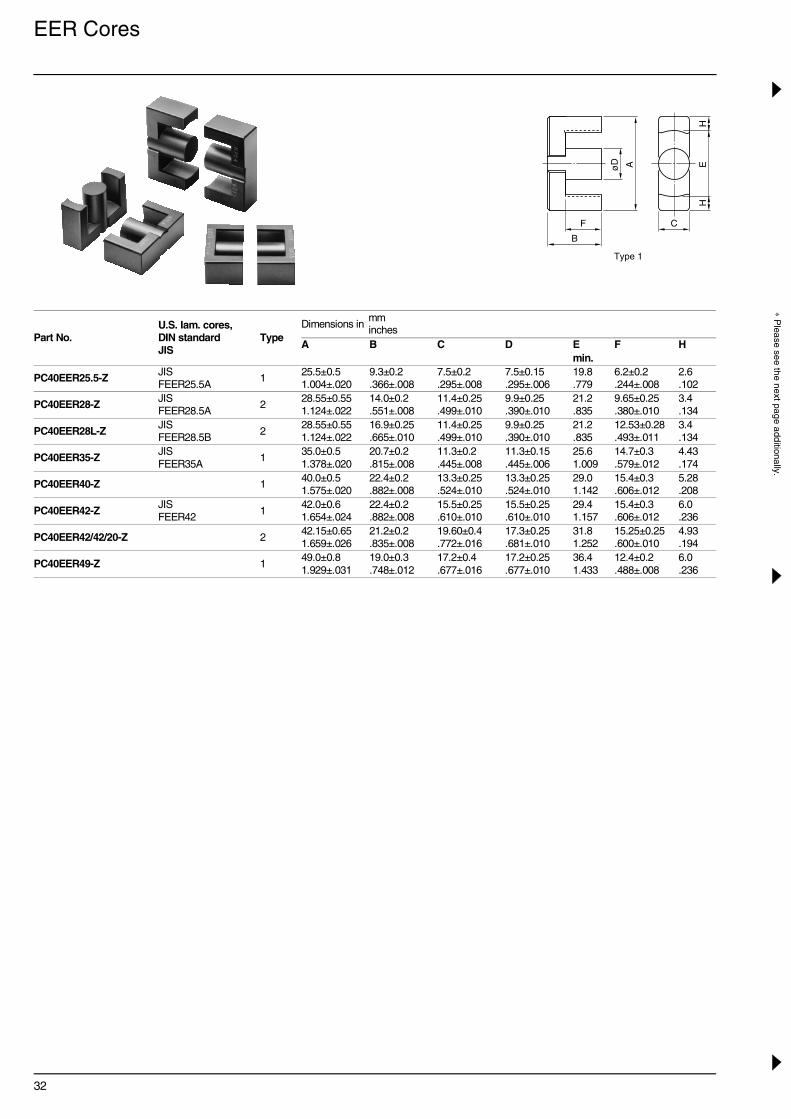
EER Cores
Part No.U.S. Iam. cores,DIN standardJIS
TypeDimensions in
A B C D E F Hmin.
PC40EER25.5-Z JIS FEER25.5A
125.5±0.5 1.004±.020
9.3±0.2 .366±.008
7.5±0.2 .295±.008
7.5±0.15.295±.006
19.8.779
6.2±0.2 .244±.008
2.6.102
PC40EER28-Z JIS FEER28.5A
228.55±0.551.124±.022
14.0±0.2 .551±.008
11.4±0.25.499±.010
9.9±0.25.390±.010
21.2.835
9.65±0.25.380±.010
3.4.134
PC40EER28L-ZJIS FEER28.5B
228.55±0.551.124±.022
16.9±0.25.665±.010
11.4±0.25.499±.010
9.9±0.25.390±.010
21.2.835
12.53±0.28.493±.011
3.4.134
PC40EER35-Z JIS FEER35A
135.0±0.5 1.378±.020
20.7±0.2 .815±.008
11.3±0.2 .445±.008
11.3±0.15.445±.006
25.61.009
14.7±0.3 .579±.012
4.43.174
PC40EER40-Z 140.0±0.5 1.575±.020
22.4±0.2 .882±.008
13.3±0.25.524±.010
13.3±0.25.524±.010
29.01.142
15.4±0.3 .606±.012
5.28.208
PC40EER42-Z JIS FEER42
142.0±0.6 1.654±.024
22.4±0.2 .882±.008
15.5±0.25.610±.010
15.5±0.25.610±.010
29.41.157
15.4±0.3 .606±.012
6.0.236
PC40EER42/42/20-Z 242.15±0.651.659±.026
21.2±0.2 .835±.008
19.60±0.4 .772±.016
17.3±0.25.681±.010
31.81.252
15.25±0.25.600±.010
4.93.194
PC40EER49-Z 149.0±0.8 1.929±.031
19.0±0.3 .748±.012
17.2±0.4 .677±.016
17.2±0.25.677±.010
36.41.433
12.4±0.2 .488±.008
6.0.236
AøD
B
F
EH
H
C
Type 1
mminches

33
∗ P
leas
e se
e th
e fo
rmer
pag
e ad
ditio
nally
.
∗ AL-value: 1kHz, 0.5mA, 100Ts∗∗ Core loss: 100kHz, 150mT, 100°C
Effective parameter Electrical characteristicsWt(g)
Bobbin itemC1
(mm–1)Ae(mm2)
e(mm)
Ve(mm3)
AL-value (nH/N2)∗ Core loss (W) max.Without air gap With air gap 100kHz, 200mT, 100°C
1.08 44.8 48.2 2160 1920±25% 100±5%200±7%
0.98 11 BEER25.5-118CPFR
0.780 82.1 64.0 5250 2870±25% 200±5%400±7%
2.30 28BEER28-1110CPFRBEER28-1112CPHFR
0.928 81.4 75.5 6150 2520±25% 160±5%315±7%
2.70 33BEER28L-1110CPFRBEER28L-1112CPHFR
0.849 107 90.8 9720 2770±25% 200±5%400±7%
4.20 52BEER35-1112CPFRBEER35-1116CPHFR
0.658 149 98.0 14600 3620±25% 200±5%400±7%
6.30 78BEER40-1112CPFRBEER40-1116CPHFR
0.509 194 98.8 19200 4690±25% 250±5%500±7%
8.60 102BEER42-1114CPFRBEER42-1116CPHFR
0.411 240 98.6 23700 5340±25% 250±5%500±7%
10.7 116 BEER42/20-1112CPFR
0.395 231 91.3 21100 6250±25% 250±5%500±7%
5.4∗∗ 110 BEER49-1118CPFR
AøD
B
FE
HH
C
Type 2

34
∗ Please see the next page additionally.
EER Bobbins
Part No. TypeDimensions in
A øB C E X Y Z
BEER25.5-118CPFR 119.53.769
9.9.390
10.05.396
4.5.177
22.0.866
19.6.772
19.05.750
BEER28-1110CPFR 120.9.823
12.3.484
16.7.657
4.5.177
24.8.976
23.0.906
26.61.047
BEER28L-1110CPFR 120.9.823
12.3.484
22.4.882
4.5.177
24.8.976
23.0.906
32.31.272
BEER35-1112CPFR 125.41.000
13.7.539
26.11.028
5.5.217
30.01.181
28.51.122
39.31.547
BEER40-1112CPFR 128.71.130
15.8.622
27.51.083
5.0.197
32.01.260
30.01.181
41.71.642
BEER42-1114CPFR 129.11.146
17.95.707
27.51.083
5.0.197
38.01.496
30.01.181
42.71.681
BEER42/20-1112CPFR 131.51.240
19.8.780
27.31.075
5.0.197
43.51.713
37.01.457
42.51.673
BEER49-1118CPFR 135.951.415
20.3.799
21.45.844
4.5.177
49.01.929
37.01.457
39.451.553
BEER28-1112CPHFR 220.9.823
12.0.472
16.1.634
5.0.197
30.01.181
31.31.232
25.0.984
BEER28L-1112CPHFR 220.9.823
12.0.472
21.8.858
5.0.197
30.01.181
37.01.457
25.0.984
BEER35-1116CPHFR 225.2.992
13.6.535
26.41.039
4.5.177
40.01.575
45.51.791
29.01.142
BEER40-1116CPHFR 228.61.126
15.7.618
27.51.083
4.2.165
40.01.575
44.01.732
31.81.252
BEER42-1116CPHFR 229.01.142
18.0.709
27.31.075
5.0.197
40.01.575
44.01.732
34.51.358
ZE
C
øP
Y
A
øB
Type 1
X
ZE
øP
Y
A
øB C
Type 2
X
P3
P2
P1
mminches
35
∗ P
leas
e se
e th
e fo
rmer
pag
e ad
ditio
nally
.
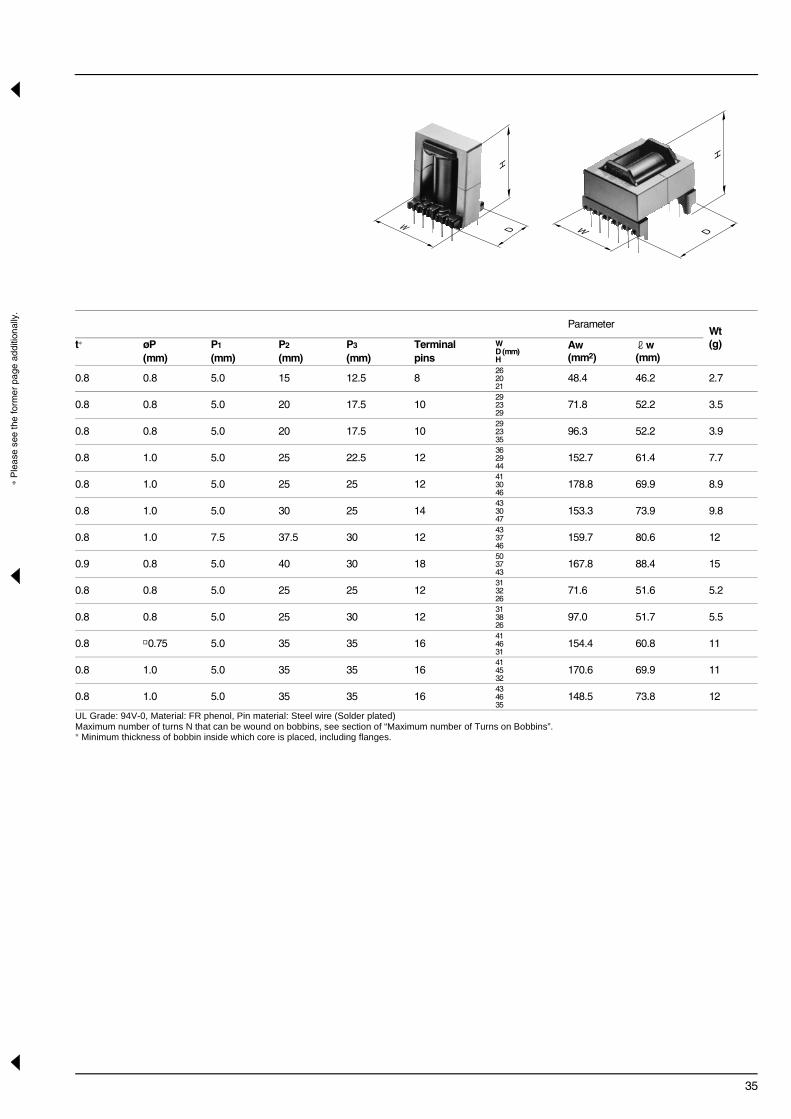
UL Grade: 94V-0, Material: FR phenol, Pin material: Steel wire (Solder plated)Maximum number of turns N that can be wound on bobbins, see section of “Maximum number of Turns on Bobbins”.∗ Minimum thickness of bobbin inside which core is placed, including flanges.
ParameterWt(g)t∗ øP P1 P2 P3 Terminal W
D (mm)H
Aw(mm2)
w(mm)(mm) (mm) (mm) (mm) pins
0.8 0.8 5.0 15 12.5 8 262021
48.4 46.2 2.7
0.8 0.8 5.0 20 17.5 10292329
71.8 52.2 3.5
0.8 0.8 5.0 20 17.5 10292335
96.3 52.2 3.9
0.8 1.0 5.0 25 22.5 12362944
152.7 61.4 7.7
0.8 1.0 5.0 25 25 12413046
178.8 69.9 8.9
0.8 1.0 5.0 30 25 14433047
153.3 73.9 9.8
0.8 1.0 7.5 37.5 30 12433746
159.7 80.6 12
0.9 0.8 5.0 40 30 18503743
167.8 88.4 15
0.8 0.8 5.0 25 25 12313226
71.6 51.6 5.2
0.8 0.8 5.0 25 30 12313826
97.0 51.7 5.5
0.8 0.75 5.0 35 35 16414631
154.4 60.8 11
0.8 1.0 5.0 35 35 16414532
170.6 69.9 11
0.8 1.0 5.0 35 35 16434635
148.5 73.8 12
H
DW
H
DW

36
∗ Please see the next page additionally.
ETD and EC Cores
Part No. JIS TypeDimensions in
A B C øD E F
PC40ETD19-Z 119.6±0.5 .771±.020
13.65±0.15.537±.006
7.4±0.2 .291±.008
7.4±0.2 .291±.008
14.9±0.5 .586±.020
9.4±0.2 .370±.008
PC40ETD24-Z 124.4±0.6 .960±.024
14.45±0.15.569±.006
8.5±0.4 .335±.016
8.5±0.2 .335±.008
18.6±0.6 .732±.024
10.1±0.2 .398±.008
PC40ETD29-Z 129.8±0.8 1.173±.031
15.80±0.15.622±.006
9.5±0.3 .374±.012
9.5±0.3 .374±.012
22.7±0.7 .893±.028
11.0±0.3 .433±.012
PC40ETD34-Z JIS FEER 34.2
134.2±0.8 1.346±.031
17.3±0.2 .681±.008
10.88±0.38.428±.015
10.8±0.3 .425±.012
26.3±0.7 1.035±.028
12.1±0.3 .476±.012
PC40ETD39-Z JIS FEER 39.1
139.1±0.9 1.539±.035
19.8±0.2 .780±.008
12.58±0.38.495±.015
12.5±0.3 .492±.012
30.1±0.8 1.185±.031
14.6±0.4 .575±.016
PC40ETD44-Z JIS FEER 44
144.0±1.0 1.732±.039
22.3±0.2 .878±.008
14.9±0.5 .587±.020
14.8±0.4 .583±.016
33.3±0.8 1.311±.031
16.5±0.4 .650±.016
PC40ETD49-Z JIS FEER 48.7
148.7±1.1 1.917±.043
24.7±0.2 .972±.008
16.4±0.5 .646±.020
16.3±0.4 .642±.016
37.0±0.9 1.457±.035
18.1±0.4 .713±.016
PC40EC70-Z 270.0±1.7 2.756±.067
34.5±0.151.358±.006
16.4±0.4 .646±.016
16.4±0.4 .646±.016
44.5±1.2 1.752±.047
22.75±0.45.896±.018
PC40EC90-Z 290.0±1.8 3.543±.071
45.0±1.3 1.772±.051
30.0±1.0 1.181±.039
30.0±1.0 1.181±.039
70.0±1.5 2.756±.059
35.5±0.5 1.398±.020
PC40EC120-Z 2120±2.0 4.724±.079
50.5±1.0 1.988±.039
30.0±1.0 1.181±.039
30.0±1.0 1.181±.039
95.0±1.7 3.740±.067
35.5±0.5 1.398±.020
AEøD
C
Type 1
B
F
mminches

37
∗ P
leas
e se
e th
e fo
rmer
pag
e ad
ditio
nally
.
∗ AL-value: 1kHz, 0.5mA, 100Ts∗∗ Core loss: 25kHz, 200mT, 100°C
Effective parameter Electrical characteristicsWt(g)
Bobbin itemC1
(mm–1)Ae(mm2)
e(mm)
Ve(mm3)
AL-value (nH/N2)∗ Core loss (W) max.Without air gap With air gap 100kHz, 200mT, 100°C
1.32 41.3 54.6 2260 1720±25% 80±5%160±7%
1.1 14 BETD19-1111CPHFR
1.100 56.3 61.9 3480 2125±25% 100±5%200±7%
1.6 20 BETD24-1112CPHFR
0.959 73.6 70.6 5170 2500±25% 200±5%400±10%
2.4 28 —
0.810 97.1 78.6 7630 2780±25% 200±5%400±7%
3.31 40 —
0.737 125 92.1 11500 3150±25% 200±5%400±7%
5.3 60 —
0.589 175 103 18000 4000±25% 250±5%400±7%
8.3 94 —
0.535 213 114 24300 4440±25% 250±5%400±7%
11.2 124 —
0.514 279 144 40100 4800±25% 100±5%200±5%
14.0 256 BEC-70-5116
0.346 624 216 135000 6000 min. 2.8∗∗ 698 BEC-90-0112
0.332 753 250 188250 6300 min. 3.5∗∗ 780 —
R
EAøD
C
Type 2
B
F

38
∗ Please see the next page additionally.
ETD and EC Bobbins
Part No. TypeDimensions in
øA øB C X Y Z
BEC-70-5116 142.71.681
19.5.768
41.45 1.632
70.02.756
56.25 2.214
57.82.276
BEC-90-0112 167.62.661
35.41.394
65.32.571
80.03.150
77.03.031
89.83.535
Part No. TypeDimensions in
øA øB C E X Y Z
BETD19-1111CPHFR 2 14.0.551
9.7 .382
16.0.630
5.0.197
23.4.921
31.01.220
18.15 .715
BETD24-1112CPHFR 2 17.5.689
10.9.429
17.2.677
5.0.197
29.01.142
33.61.223
21.65 .852
1 432
8 567
C
Z
Y øB
Type 1
X
Terminal number
R
a′
a
øAa-a′ Section
mminches
mminches

39
∗ P
leas
e se
e th
e fo
rmer
pag
e ad
ditio
nally
.
UL Grade: 94V-0, Material: FR phenol, Pin material: Steel wire (Solder plated)Maximum number of turns N that can be wound on bobbins, see section of “Maximum number of Turns on Bobbins”.∗ Minimum thickness of bobbin inside which core is placed, including flanges.
ParameterWt(g)
Material Accessory itemt∗ W
D (mm)H
Aw(mm2)
w(mm)
1.13725770
471.4 98 18 6-Nylon —
1.90927793
1046.5 162 82 6-Nylon —
ParameterWt(g)t∗ øP P1 P2 P3 Terminal W
D (mm)H
Aw(mm2)
w(mm)(mm) (mm) (mm) (mm) pins
0.9 0.8 5.08 20.32 20.32 1023.55 31.018.15
37.3 33.2 3.3
0.9 0.8 5.08 25.4 22.86 1229.033.621.65
44.7 55.5 4.8
ZE
Y
A
øB C
Type 2
X
øP
H
DW
H
DW
Bobbin-core assembly dimensions
EC cores ETD cores

41
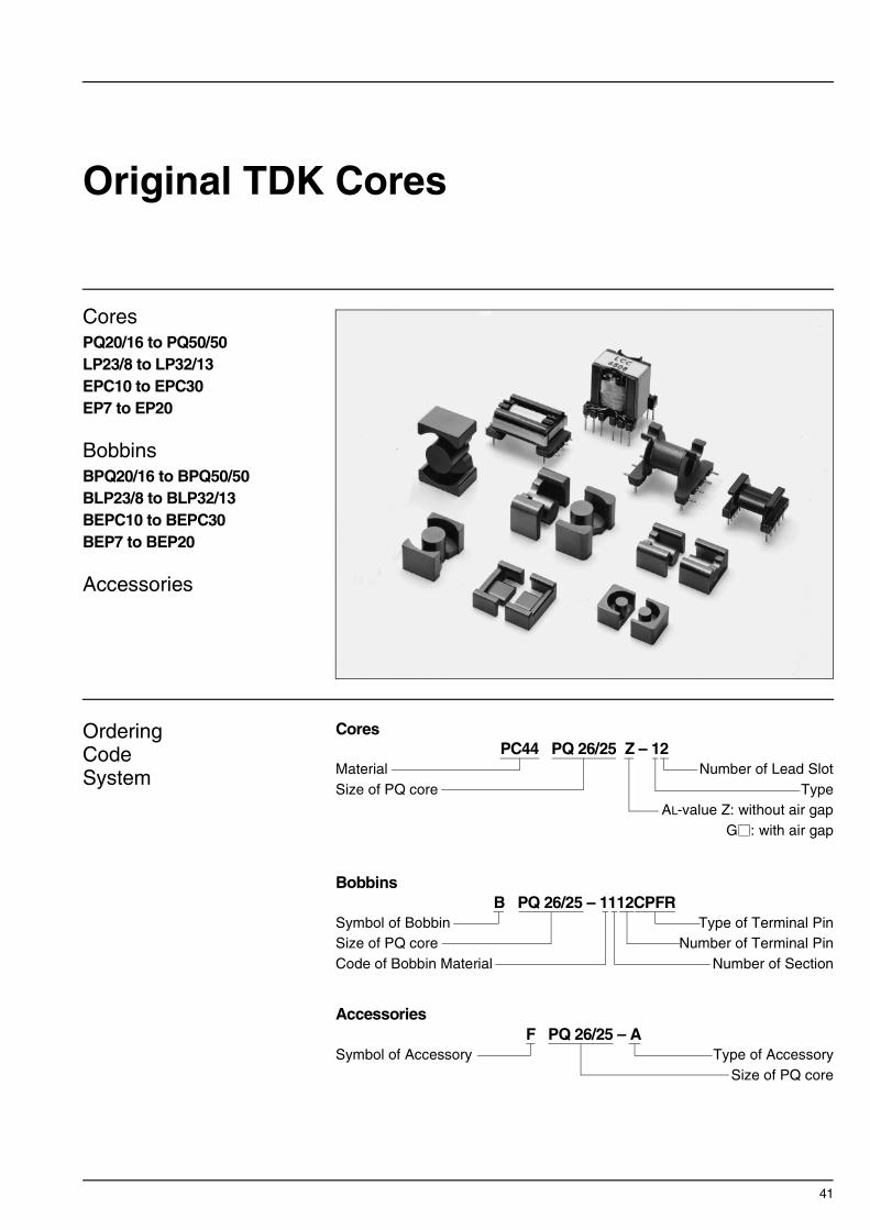
Original TDK Cores
CoresPQ20/16 to PQ50/50LP23/8 to LP32/13EPC10 to EPC30EP7 to EP20
BobbinsBPQ20/16 to BPQ50/50BLP23/8 to BLP32/13BEPC10 to BEPC30BEP7 to BEP20
Accessories
OrderingCodeSystem
Cores
Bobbins
Accessories
PC44 PQ 26/25 Z – 12MaterialSize of PQ core
Number of Lead SlotType
AL-value Z: without air gapG : with air gap
B PQ 26/25 – 1112CPFRSymbol of BobbinSize of PQ coreCode of Bobbin Material
Type of Terminal PinNumber of Terminal Pin
Number of Section
F PQ 26/25 – ASymbol of Accessory Type of Accessory
Size of PQ core
42
∗ Please see the next page additionally.
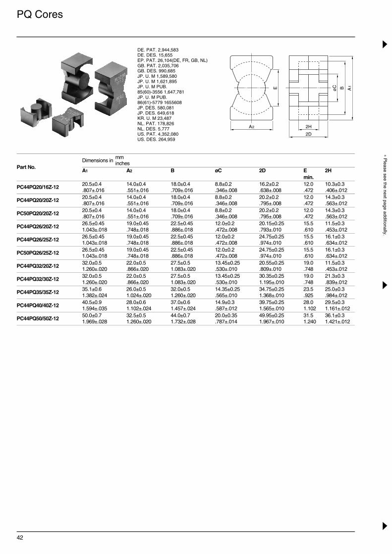
PQ Cores
Part No.Dimensions in
A1 A2 B øC 2D E 2Hmin.
PC44PQ20/16Z-12 20.5±0.4 .807±.016
14.0±0.4 .551±.016
18.0±0.4 .709±.016
8.8±0.2 .346±.008
16.2±0.2 .638±.008
12.0.472
10.3±0.3 .406±.012
PC44PQ20/20Z-12 20.5±0.4 .807±.016
14.0±0.4 .551±.016
18.0±0.4 .709±.016
8.8±0.2 .346±.008
20.2±0.2 .795±.008
12.0.472
14.3±0.3 .563±.012
PC50PQ20/20Z-12 20.5±0.4 .807±.016
14.0±0.4 .551±.016
18.0±0.4 .709±.016
8.8±0.2 .346±.008
20.2±0.2 .795±.008
12.0.472
14.3±0.3 .563±.012
PC44PQ26/20Z-12 26.5±0.451.043±.018
19.0±0.45.748±.018
22.5±0.45.886±.018
12.0±0.2 .472±.008
20.15±0.25.793±.010
15.5.610
11.5±0.3 .453±.012
PC44PQ26/25Z-12 26.5±0.451.043±.018
19.0±0.45.748±.018
22.5±0.45.886±.018
12.0±0.2 .472±.008
24.75±0.25.974±.010
15.5.610
16.1±0.3 .634±.012
PC50PQ26/25Z-12 26.5±0.451.043±.018
19.0±0.45.748±.018
22.5±0.45.886±.018
12.0±0.2 .472±.008
24.75±0.25.974±.010
15.5.610
16.1±0.3 .634±.012
PC44PQ32/20Z-12 32.0±0.5 1.260±.020
22.0±0.5 .866±.020
27.5±0.5 1.083±.020
13.45±0.25.530±.010
20.55±0.25.809±.010
19.0.748
11.5±0.3 .453±.012
PC44PQ32/30Z-12 32.0±0.5 1.260±.020
22.0±0.5 .866±.020
27.5±0.5 1.083±.020
13.45±0.25.530±.010
30.35±0.251.195±.010
19.0.748
21.3±0.3 .839±.012
PC44PQ35/35Z-12 35.1±0.6 1.382±.024
26.0±0.5 1.024±.020
32.0±0.5 1.260±.020
14.35±0.25.565±.010
34.75±0.251.368±.010
23.5.925
25.0±0.3 .984±.012
PC44PQ40/40Z-12 40.5±0.9 1.594±.035
28.0±0.6 1.102±.024
37.0±0.6 1.457±.024
14.9±0.3 .587±.012
39.75±0.251.565±.010
28.01.102
29.5±0.3 1.161±.012
PC44PQ50/50Z-12 50.0±0.7 1.969±.028
32.5±0.5 1.260±.020
44.0±0.7 1.732±.028
20.0±0.35.787±.014
49.95±0.251.967±.010
31.51.240
36.1±0.3 1.421±.012
DE. PAT. 2,944,583DE. DES. 15,655 EP. PAT. 26,104(DE, FR, GB, NL) GB. PAT. 2,035,706GB. DES. 990,685JP. U. M 1,589,580JP. U. M 1,621,895JP. U. M PUB. 85(60)-3556 1,647,781 JP. U. M PUB.86(61)-5779 1655608 JP. DES. 580,081JP. DES. 649,618KR. U. M 23,487 NL. PAT. 178,826NL. DES. 5,777US. PAT. 4,352,080US. DES. 264,959
A1BøCE
A2
2D
2H
mminches

43
∗ P
leas
e se
e th
e fo
rmer
pag
e ad
ditio
nally
.
∗ AL-value: 1kHz, 0.5mA, 100Ts∗∗ Core loss: 100kHz, 150mT, 100°C∗∗∗ Core loss: 500kHz, 50mT, 100°C
Effective parameter Electrical characteristicsWt(g)
Bobbin itemC1
(mm–1)Ae(mm2)
e(mm)
Ve(mm3)
AL-value (nH/N2)∗ Core loss (W) max.Without air gap With air gap 100kHz, 200mT, 100°C
0.603 62 37.4 2320 3880±25% 100±5%250±7%400±10%
0.84 13 BPQ20/16-1114CPFR
0.732 62 45.4 2810 3150±25% 100±5%250±7%400±10%
1.02 15 BPQ20/20-1114CPFR
0.732 62 45.4 2810 2000±25% 100±5%160±5%250±7%
0.33∗∗∗ 15 BPQ20/20-1114CPFR
0.389 119 46.3 5510 6170±25% 160±5%315±5%630±10%
1.94 31 BPQ26/20-1112CPFR
0.470 118 55.5 6550 5250±25% 160±5%315±5%630±10%
2.32 36 BPQ26/25-1112CPFR
0.470 118 55.5 6550 3200±25% 100±5%250±5%400±7%
0.76∗∗∗ 36 BPQ26/25-1112CPFR
0.326 170 55.5 9440 7310±25% 160±5%315±5%630±7%
2.92 42 BPQ32/20-1112CPFR
0.463 161 74.6 12000 5140±25% 160±5%315±5%630±7%
3.92 55 BPQ32/30-1112CPFR
0.448 196 87.9 17200 4860±25% 160±5%315±5%630±7%
5.27 73 BPQ35/35-1112CPFR
0.507 201 102 20500 4300±25% 160±5%315±5%630±7%
6.56 95 BPQ40/40-1112CPFR
0.346 328 113 37238 6720±25% 250±5%400±5%630±5%
6.10∗∗ 195 BPQ50/50-1112DSFR

44
∗ Please see the next page additionally.
PQ Bobbins
Connecting Pin Patterns (2.54mm/0.1 inch grids) View in mounting direction
Part No.Dimensions in
A øB C E X Y Z
BPQ20/16-1114CPFR 17.2 .677
10.95 .431
8.0 .315
6.5 .256
23.0.906
23.0.906
18.3.720
BPQ20/20-1114CPFR 17.2.677
10.95.431
12.0.472
6.5 .256
23.0.906
23.0.906
22.3.878
BPQ26/20-1112CPFR21.6.850
14.3 .563
9.2 .362
6.5 .256
26.51.043
29.31.154
21.5.846
BPQ26/25-1112CPFR21.6.850
14.3 .563
13.9.547
3.5 .138
26.51.043
29.31.154
29.11.146
BPQ32/20-1112CPFR 26.6 1.047
16.0.630
9.0 .354
7.0 .276
32.01.260
34.01.339
22.5.886
BPQ32/30-1112CPFR26.61.047
16.0 .630
18.6.732
7.0 .276
32.01.260
34.01.339
32.11.264
BPQ35/35-1112CPFR31.1 1.224
16.9.665
22.4.882
7.5 .295
35.01.378
39.01.535
37.41.472
BPQ40/40-1112CPFR36.01.417
17.5 .689
26.81.055
6.5 .256
40.01.575
42.01.654
44.81.764
BPQ50/50-1112DSFR 42.91.689
23.2.913
32.41.276
10.0.394
51.02.008
51.02.008
52.02.047
Y
X
ZE
C
øP
Bobbins
mminches
Item BPQ32/20-1112CPFRItem BPQ20/16-1114CPFR Item BPQ26/20-1112CPFR
10.6
32.4
20.8
26.8
BPQ32/20FPQ32/20-A
FPQ20/16-A BPQ20/16FPQ26/20-A
Item BPQ32/30-1112CPFR
10.6
32.4BPQ32/30FPQ32/30-A
6.4
9.0
Item BPQ20/20-1114CPFR
20.8FPQ20/20-A BPQ20/20
BPQ26/20
Item BPQ26/25-1112CPFR
26.8FPQ26/25-A
9.0
BPQ26/25
6.4

45
∗ P
leas
e se
e th
e fo
rmer
pag
e ad
ditio
nally
.
UL Grade: 94V-0, Material: FR phenol, Pin material: Steel wire (Solder plated)Maximum number of turns N that can be wound on bobbins, see section of “Maximum number of Turns on Bobbins”.∗ Minimum thickness of bobbin inside which core is placed, including flanges.
ParameterWt(g)
Accessory itemt∗ øP Terminal W
D (mm)H
Aw(mm2)
w(mm)(mm) pins
0.8 0.6 1423.023.018.3
23.4 44 2.7 FPQ20/16-A
0.8 0.6 1423.023.022.3
36.2 44 2.8 FPQ20/20-A
0.8 0.8 1226.529.321.5
30.7 56.2 4.3 FPQ26/20-A
0.8 0.8 1226.529.329.1
47.7 56.2 4.9 FPQ26/25-A
0.9 1.0 1232.034.022.5
42.9 67.1 6.6 FPQ32/20-A
0.9 1.0 1232.034.032.1
95.3 67.1 7.4 FPQ32/30-A
0.9 1.0 1235.039.037.4
154.2 75.2 11 FPQ35/35-A
0.9 1.0 1240.042.044.8
240.0 83.9 14 FPQ40/40-A
1.0 1.2 1251.051.052.0
313.0 104 22 FPQ50/50-B
AøB
H
DW
Item BPQ50/50-1112DSFRItem BPQ40/40-1112CPFRItem BPQ35/35-1112CPFR
11.3
11.8
40.935.5
for bobbinfor clamp
Dimensions in mm
FPQ35/35-AFPQ40/40-A
BP
Q35
/35
BP
Q40
/40
BPQ50/50
FPQ50/50-B

46
∗ Please see the next page additionally.
LP Cores and Bobbins
∗ Include 2 pieces of insulating dividers (see next page).
Part No.Dimensions in
A B øC 2D E 2H I
PC44LP23/8Z-12 16.5±0.3 .650±.012
12.5±0.3 .492±.012
5.7±0.1 .224±.004
23.4±0.2 .921±.008
8.7±0.2 .343±.008
17.4±0.2 .685±.008
9.0±0.5 .354±.020
PC44LP22/13Z-12 25.0±0.4 .984±.016
19.0±0.3 .748±.012
8.6±0.2 .339±.008
22.4±0.2 .882±.008
12.9±0.3 .508±.012
16.4±0.3 .646±.012
13.5±0.5 .531±.020
PC44LP32/13Z-12 25.0±0.4 .984±.016
19.0±0.3 .748±.012
8.6±0.2 .339±.008
31.8±0.2 1.252±.008
12.9±0.3 .508±.012
24.1±0.3 .949±.012
13.5±0.5 .531±.020
Part No. TypeDimensions in
A B C E X Y Z
BLP23/8-018CPLFR 1 12.0.472
7.7 .303
15.2.598
4.0 .157
16.5.650
34.01.358
12.5.492
BLP22/13-018CPLFR 1 17.6.693
10.7.421
14.1.555
4.0 .157
25.0.984
31.51.240
17.6.693
BLP22/13-1110CPLFR∗ 2 17.6 .693
10.78.424
13.4.528
4.0 .157
25.0.984
32.31.272
19.1.752
BLP32/13-018CPLFR 1 17.6.693
10.7.421
21.8.858
4.0 .157
25.0.984
40.41.591
17.6.693
BLP32/13-1110CPLFR∗ 2 17.6.693
10.82.426
21.1 .835
4.0 .157
25.0.984
40.61.598
19.1.752
Cores
I
E
2D
2H
A
B
øC
DE. DES. 19,581 EP. PAT. 68,745(DE, FR, GB, NL) FR. DES. 201,586GB. DES. 1,007,200JP. U. M PRO. PUB. 82(57)-201,824JP. DES. 630,754NL. DES. 9,767US. PAT. 4,424,504US. DES. 280,810
mminches
A C
øB
X YøP
ZE
Type 1
Bobbins
mminches
25.4
Pin layoutItem BLP23/8-018CPLFR
Pin layoutItem BLP22/13-018CPLFR
Pin layoutItem BLP22/13-1110CPLFR
Pin layoutItem BLP32/13-018CPLFR
Pin layoutItem BLP32/13-1110CPLFR
3.81
3.81
3.81
20.32
5.08
5.08
5.08
5.08
27.94
5.08
5.08
5.08
5.08
20.32
6.35
6.35
6.35
27.94
6.35
6.35
6.35
Dimensions in mm

47
∗ P
leas
e se
e th
e fo
rmer
pag
e ad
ditio
nally
.
∗ AL-value: 1kHz, 0.5mA, 100Ts
UL Grade: 94V-0, Pin material: Phosphor bronze wire/Steel wire for “-1110-CPLFR” (Solder plated), Insulating divider’s material: NOMEX®
Maximum number of turns N that can be wound on bobbins, see section of “Maximum number of Turns on Bobbins”.∗ Minimum thickness of bobbin inside which core is placed, including flanges.
Effective parameter Electrical characteristicsWt(g)
Bobbin itemC1
(mm–1)Ae(mm2)
e(mm)
Ve(mm3)
AL-value (nH/N2)∗ Core loss (W) max.Without air gap With air gap 100kHz, 200mT, 100°C
1.41 31.3 44.1 1380 1600±25% 63±5%100±7%250±13%
0.42 9.6 BLP23/8-018PFR
0.721 67.9 49.0 3330 3310±25% 100±5%200±7%400±10%
1.05 21 BLP22/13-1110CPLFR
0.909 70.3 64.0 4500 2630±25% 100±5%200±7%400±10%
1.38 30 BLP32/13-1110CPLFR
ParameterWt(g)
Material Clamp itemt∗ øP Terminal W
D (mm)H
Aw(mm2)
w(mm)(mm) pins
0.8 0.6 8 17.234.212.5
31.9 30.9 1.9 PPS FLP23/8-A
0.8 0.8 8 273217.8
51.5 45.8 3.2 PPS FLP22/13-A
0.8 0.8 1025.932.319.2
45.7 44.5 3.1 FR Phenol FLP22/13-A
0.8 0.8 8 274117.8
79.6 45.8 3.7 PPS FLP32/13-A
0.8 0.8 1025.940.619.2
72.0 44.5 3.7 FR Phenol FLP32/13-A
ZE
øB
Y
A C
Type 2
X
øP
H
W
D
24.0
18.3 18.3
8.3
6.5
24.0
9.8
8.0
t=0.5t=0.5
Dimensions in mm
Insulating divider for BLP22/13-1110CPLFRPart No.: ILP22/13
Insulating divider for BLP32/13-1110CPLFRPart No.: ILP32/13

48
∗ Please see the next page additionally.
EPC Cores
Part No. TypeDimensions in
A B C1 C2 D E Fmin. min.
PC44EPC10-Z PC50EPC10-Z
310.2±0.2 .402±.008
7.6 .299
5.0±0.1 .197±.004
1.9±0.1 .075±.004
4.05±0.10.159±.004
5.3 .209
3.4±0.1 .139±.004
PC44EPC13-Z PC50EPC13-Z
113.25±0.30.522±.012
10.5.413
5.60±0.15.220±.006
2.05±0.10.081±.004
6.6±0.2 .026±.008
8.3 .327
4.60±0.15.181±.006
PC44EPC17-Z PC50EPC17-Z 1
17.6±0.4 .693±.016
14.3.563
7.70±0.15.303±.006
2.8±0.1 .110±.004
8.55±0.20.337±.008
11.5.453
6.00±0.15.236±.006
PC44EPC19-Z PC50EPC19-Z
119.1±0.4 .752±.016
15.8.622
8.50±0.15.335±.006
2.5±0.1 .098±.004
9.75±0.20.384±.008
13.1.516
6.00±0.15.236±.006
PC44EPC25-Z PC50EPC25-Z
125.1±0.5 .988±.020
20.65 .813
11.5±0.2 .453±.008
4.0±0.1 .157±.004
12.5±0.2 .492±.008
17.1.673
8.0±0.2 .315±.008
PC44EPC25B-ZPC50EPC25B-Z 2
25.1±0.5 .988±.020
20.4.803
13.8±0.2 .543±.008
2.50±0.15.098±.006
11.4±0.15.449±.006
16.5.650
6.5±0.2 .266±.008
PC44EPC27-Z PC50EPC27-Z 1
27.1±0.5 1.067±.020
21.6.850
13.0±0.3 .512±.012
4.0±0.1 .157±.004
16.0±0.2 .630±.008
18.5.728
8.0±0.2 .315±.008
PC44EPC27N-Z 427.0±0.4 1.063±.016
20.8.819
13.85±0.15.545±.006
2.2±0.1 .087±.004
13.0±0.1 .512±.004
19.0.748
5.1±0.1 .201±.004
PC44EPC30-Z PC50EPC30-Z
130.1±0.5 1.185±.020
23.6.929
15.0±0.3 .591±.012
4.0±0.1 .157±.004
17.5±0.2 .689±.008
20.0.787
8.0±0.2 .315±.008
AccessoryPart No.
Dimensions in
A B C D E t Material
FEPC-10-A 10.8.425
2.8 .110
1.5 .059
8.0 .315
0.8 .031
0.2 .008
Stainless steel
FEPC-13-A 13.7.541
2.8 .110
2.9 .114
14.75 .581
2.65.104
0.25.010
Stainless steel
FEPC-17-A 18.1 .713
3.8 .150
2.9 .114
19.1.752
3.0 .118
0.3 .012
Stainless steel
FEPC-19-A 19.9.783
3.8.150
2.9 .114
21.5.846
3.0 .118
0.3 .012
Stainless steel
FEPC-25-A 26.0 1.024
5.6.220
2.9 .114
27.01.063
3.0 .118
0.3 .012
Stainless steel
FEPC-25B-A26.01.024
5.0.197
2.9 .114
24.5.965
3.0 .118
0.3 .012
Stainless steel
FEPC-27-A 28.0 1.102
5.6 .220
2.9 .114
34.01.339
3.0 .118
0.3 .012
Stainless steel
FEPC-30-A 31.01.220
5.6.220
2.9 .114
37.01.457
3.0 .118
0.3 .012
Stainless steel
Cores
E
Type 1
F
C2
D
H
A
B
C1
US. PAT. 4,760,366EP. PAT. 245,083(DE, FR, GB, NL)KS. UM 50,836 TW. UM 39,406 JP. PENDING
mminches
mminches
A B
DE
Ct

49
∗ P
leas
e se
e th
e fo
rmer
pag
e ad
ditio
nally
.
∗ AL-value: 1kHz, 0.5mA, 100Ts∗∗ Core loss: 500kHz, 50mT, 100°C
Effective parameter Electrical characteristicsWt(g)
Bobbin itemH C1
(mm–1)Ae(mm2)
e(mm)
Ve(mm3)
AL-value (nH/N2)∗ Core loss (W) max.Without air gap With air gap 100kHz, 200mT, 100°C
2.65±0.10.104±.004
1.89 9.39 17.8 1671000±25% 660±25%
40±7%63±10%
0.0720.025∗∗ 1.1 BEPC10-118GAFR
4.5±0.2.177±.008
2.45 12.5 30.6 382870±25%560±25%
40±4%63±5%
0.140.039∗∗ 2.1
BEPC13-1110CPHFRBEPC13-1110GAFR
6.05±0.20.238±.008
1.76 22.8 40.2 9171150±25% 740±25%
80±4%125±5%
0.350.1∗∗
4.5BEPC17-1110CPHFRBEPC17-119GAFR
7.25±0.20.285±.008
2.03 22.7 46.1 1050940±25% 680±25%
80±4%125±5%
0.40.12∗∗ 5.3
BEPC19-1111CPHFRBEPC19-1110GAFR
9.0±0.3.354±.012
1.28 46.4 59.2 27501560±25% 1080±25%
125±5%200±7%
1.110.32∗∗ 13 BEPC25-1111CPHFR
8.75±0.15.344±.006
1.39 33.3 46.2 15401560±25%1080±25%
80±5%125±7%
0.650.22∗∗ 11 BEPC25B-1111GAFR
12.0±0.3.472±.012
1.34 54.6 73.1 40001540±25% 1030±25%
125±5%200±7%
1.560.46∗∗ 18 BEPC27-1111CPHFR
8.5±0.1.335±.004
1.70 33.0 55.9 1840 1400±25% 80±5%125±7%
0.73 10 BEPC27N-1114CPHFR
13.0±0.3.512±.012
1.34 61.0 81.6 49801570±25% 1060±25%
125±5%200±7%
2.030.58∗∗ 23 BEPC30-1112CPHFR
E
Type 2
F
C2
D
H
A
B
C1
E
Type 3
F
C2
D
H
A
B
C1
E
Type 4
F
C2
D
H
A
B
C1

50
∗ Please see the next page additionally.
EPC Bobbins and Accessories
Bobbin (Lead through type)Part No.
Dimensions in
A B C D E X Y Z
BEPC13-1110CPHFR 10.22 .402
6.93.273
6.88.271
0.9 .035
2.5 .098
13.2.520
13.2 .520
7.5 .295
BEPC17-1110CPHFR14.07 .554
9.88.389
9.55.376
2.5 .098
4.5 .177
17.2.677
17.5 .689
11.9.469
BEPC19-1111CPHFR15.57 .613
10.78 .424
11.95 .470
2.5 .098
4.5 .177
18.7.736
19.0.748
11.9.469
BEPC25-1111CPHFR 20.37 .802
13.73 .541
14.7.579
3.0 .118
4.5 .177
25.0.984
25.0.984
16.0.630
BEPC27-1111CPHFR 21.32 .839
15.33 .604
20.7.815
3.0 .118
4.5 .177
27.01.063
32.0 1.260
16.0 .630
BEPC27N-1114CPHFR20.5.807
15.9.623
16.5.650
0.3 .012
3.5 .138
28.51.122
29.81.173
8.7 .343
BEPC30-1112CPHFR23.32 .918
17.33 .682
22.7.894
3.0 .118
4.5 .177
30.0 1.181
35.01.378
16.0 .630
Bobbin (SMD type)Part No.
Dimensions in
A B C D E X Y Z
BEPC10-118GAFR7.5 .295
5.95.234
3.9 .154
— —10.8.425
11.5.453
4.85.193
BEPC13-1110GAFR10.3.406
6.93.273
6.9 .272
— —14.0.551
20.4.803
7.02.276
BEPC17-119GAFR14.1.555
9.9 .390
9.6 .378
— —17.5.689
23.0.906
9.8.386
BEPC19-1110GAFR 15.4.606
10.7.421
12.0.472
— —20.0.787
25.0.984
9.75.384
BEPC25B-1111GAFR20.1.791
15.7.618
14.7.579
— —25.0.984
28.71.130
9.8 .386
Bobbin (Drop in type)Part No.
Dimensions in
A B C D E X Y Z
BEPC19-1110SAFR15.6.611
10.7.413
12.0.480
18.6.835
—20.0.768
26.01.228
9.55.337
BEPC25B-1111SFR 20.2.795
16.0.630
14.7.579
21.7.854
—25.0.984
37.71.484
9.40.370
Z
D
Y
A
B C
XP
ZE
D
Y
A
B C
X
øP
Z
Y
A
B C
XPw
Pt
SMD type
Lead through type Drop in type
mminches
mminches
mminches

51
∗ P
leas
e se
e th
e fo
rmer
pag
e ad
ditio
nally
.
UL Grade: 94V-0, Material: FR phenol, Pin material: Steel wire (Solder plated), Phosphor bronze (Solder plated) for BEPC25B-1111GAFR only.Maximum number of turns N that can be wound on bobbins, see section of “Maximum number of Turns on Bobbins”.∗ Minimum thickness of bobbin inside which core is placed, including flanges.
ParameterWt(g)
Connectingpin patternt∗ øP P1 P2 P3 Terminal W
D (mm)H
Aw(mm2)
w(mm)(mm) (mm) (mm) (mm) pins
0.5 0.49 2.5 — 10.5 1013.914.87.7
11.2 23.0 0.57 Type 4
0.9 0.49 3.75 2.5 15.0 1018.219.112.1
20.1 32.1 1.5 Type 1
0.9 0.49 3.75 2.5 16.25 1120.021.512.1
29.3 34.4 1.6 Type 2
0.9 0.8 5.0 3.75 20.0 1126.127.016.2
54.4 45.0 3.9 Type 2
0.9 0.8 5.0 3.75 27.5 1128.134.016.2
62.1 47.2 4.7 Type 2
0.8 0.8 3.75 — 25.0 1429.036.59.0
32.4 43.7 3.1 Type 3
0.9 1.0 5.0 — 30.0 1231.137.016.2
68.1 51.1 6.0 Type 3
ParameterWt(g)
Connectingpin patternt∗ Pt×Pw P1 P2 P3 Terminal W
D (mm)H
Aw(mm2)
w(mm)(mm) (mm) (mm) (mm) pins
0.35 0.3×0.5 2.0 — 10.8 8 11.011.75.2
3.2 17.5 0.14 Type 6
0.5 0.4×0.7 3.0 — 18.5 1014.220.67.3
11.6 23.1 0.6 Type 7
0.8 0.4×0.7 5.0 3.5 21.8 9 18.223.29.9
20.1 32.1 1.1 Type 8
0.8 0.4×0.7 5.0 3.5 23.8 1020.225.29.9
28.2 34.4 1.3 Type 9
0.8 0.4×0.8 5.0 3.5 27.5 1126.128.99.9
32.3 44.3 1.9 Type 10
ParameterWt(g)
Connectingpin patternt∗ Pt×Pw P1 P2 P3 Terminal W
D (mm)H
Aw(mm2)
w(mm)(mm) (mm) (mm) (mm) pins
0.8 0.4×0.7 5.0 3.5 24.0 1020.226.29.8
28.2 34.4 1.3 Type 9
0.8 0.49 5.0 3.5 34.7 1126.037.99.5
30.9 50.5 2.1 Type 10
H
WD
H
W
D
P2
P1
P3
P1
P3
P2
P1 P1
P3
P1
P3
Type 1
P1
Type 6
P1
P3
P1
Type 7
P2
P3
P1
Type 8
P2
P3
P1
Type 9
P2
P3
P1
Type 10
Type 2 Type 3P1
P1
P3
Type 4
H
W D

52
∗ Please see the next page additionally.
EP Cores and Bobbins
Part No.Dimensions in
A B øC 2D E 2H
PC40EP7-Z 9.2±0.2 .362±.008
7.4±0.2 .291±.008
3.3±0.1 .130±.004
7.4±0.1 .291±.004
6.35±0.15.250±.006
5.2±0.2 .205±.008
PC40EP10-ZPC50EP10-Z
11.5±0.3 .453±.012
9.4±0.2 .370±.008
3.3±0.15.130±.006
10.2±0.2 .402±.008
7.65±0.2 .301±.008
7.4±0.2 .291±.008
PC40EP13-ZPC50EP13-Z
12.5±0.3 .492±.012
10.0±0.3 .394±.012
4.35±0.15.171±.006
12.85±0.15.506±.006
8.8±0.2 .346±.008
9.2±0.2 .362±.008
PC40EP17-Z18.0±0.4 .709±.016
12.0±0.4 .472±.016
5.68±0.18.224±.007
16.8±0.2 .661±.008
11.0±0.25.433±.010
11.3±0.3 .445±.012
PC40EP20-Z24.0±0.5 .945±.020
16.5±0.4 .650±.016
8.75±0.25.344±.010
21.4±0.2 .843±.008
14.95±0.35.589±.014
14.3±0.3 .563±.012
Part No.Dimensions in
A øB C E X Y Z
BEP7-316DFR 7.0.276
4.5 .177
3.1 .122
3.0 .118
9.2 .362
7.4 .291
8.25.325
BEP10-318DFR8.8.346
4.8 .189
5.6 .220
5.2 .205
11.0.433
11.0.433
10.2.402
BEP13-3110DFR9.6.378
5.7 .224
7.7 .303
5.3 .209
13.2.520
13.5.531
10.75 .423
BEP17-318DFR 11.4.449
7.2 .283
9.4 .370
5.0 .197
19.0.748
19.0.748
13.2.520
BEP20-8110DFR15.9.626
10.2.402
12.4.488
5.0 .197
24.7.972
21.5.846
16.6.654
Cores
2D
2H
ABøC
E
mminches
Bobbins
ZE
YX
CA
øB
øP
mminches

53
∗ P
leas
e se
e th
e fo
rmer
pag
e ad
ditio
nally
.
∗ AL-value: 1kHz, 0.5mA, 100Ts ∗∗ Core loss: 500kHz, 50mT, 100°C
UL Grade: 94V-0, Material: FR phenol, Pin material: Phosphor bronze (Solder plated)Maximum number of turns N that can be wound on bobbins, see section of “Maximum number of Turns on Bobbins”.∗ Minimum thickness of bobbin inside which core is placed, including flanges.
Effective parameter Electrical characteristicsWt(g)
Bobbin itemC1
(mm–1)Ae(mm2)
e(mm)
Ve(mm3)
AL-value (nH/N2)∗ Core loss (W) max.Without air gap With air gap 100kHz, 200mT, 100°C
1.52 10.3 15.7 162 830 min.63±5%100±7%
0.065 1.4 BEP7-316DFR
1.70 11.3 19.2 217800 min.800±25%
63±5%100±7%
0.080.02∗∗ 2.8 BEP10-318DFR
1.24 19.5 24.2 4721170 min. 1100±25%
100±5%160±7%
0.170.044∗∗ 5.1 BEP13-3110DFR
0.84 33.9 28.5 966 1840 min. 100±5%250±7%
0.33 12 BEP17-318DFR
0.508 78 39.8 3120 3200 min. 100±5%250±7%
1.1 28 BEP20-8110DFR
ParameterWt(g)
Accessory itemt∗ øP P1 P2 P3 Terminal W
D (mm)H
Aw(mm2)
w(mm)(mm) (mm) (mm) (mm) pins
0.25 0.6 2.5 5.0 5.0 6 9.4 7.5 9.6
3.85 18.1 0.3 FEP-7-C
0.40 0.6 2.5 7.5 7.5 8 11.811.211.8
11.7 21.7 0.65 FEP-10-C
0.35 0.6 2.5 10.0 10.0 1013.413.712.7
16.6 23.9 0.74 FEP-13-C
0.45 0.6 5.0 15.0 15.0 8 19.25 19.25 15.7
19.0 29.1 1.3 FEP-17-C
0.325 0.6 5.0 20.0 17.5 1025.021.819.6
33.2 40.8 1.8 FEP-20-C
P3
P2
P1 ø1.2
D
H
W


55
RM Cores
CoresRM4 to RM14
BobbinsBRM4 to BRM14
AccessoriesFRM4 to FRM14
OrderingCodeSystem
Cores
Bobbins
Accessories
PC40 RM6 A160 – 12MaterialSize of RM coreAL-value(Z: without air gap)
Number of Lead SlotType
B RM6 – 714 CPFRSymbol of BobbinSize of RM coreCode of Bobbin Material
Type of Terminal PinNumber of Terminal Pin
Number of Section
F RM6 – AFRSymbol of Accessory Type of Accessory
Size of RM core

56
∗ Please see the next page additionally.
RM Cores
Part No. TypeDimensions in
A B øC 2D E F 2Hmin.
PC40RM4Z-12 PC50RM4Z-12
1 9.63±0.18.379±.007
8.15±0.2 .321±.008
3.8±0.1 .150±.004
10.4±0.1 .409±.004
5.8 .228
10.8±0.2 .425±.008
7.2±0.2 .283±.008
PC40RM5Z-12 PC50RM5Z-12
1 12.05±0.25.474±.010
10.4±0.2 .409±.008
4.8±0.1 .189±.004
10.4±0.1 .409±.004
6.0 .236
14.3±0.3 .563±.012
6.5±0.2 .256±.008
PC40RM6Z-12 PC50RM6Z-12 3
14.4±0.3 .567±.012
12.65±0.25.498±.010
6.3±0.1 .248±.004
12.4±0.1 .488±.004
8.4 .331
17.6±0.3 .693±.012
8.2±0.2 .323±.008
PC40RM8Z-12 2 19.35±0.35.762±.014
17.3±0.3 .681±.012
8.4±0.15.331±.006
16.4±0.1 .646±.004
9.8 .386
22.75±0.45.896±.018
11.0±0.2 .433±.008
PC40RM10Z-12 2 24.15±0.55.951±.022
21.65±0.45.852±.018
10.7±0.2 .421±.008
18.6±0.1 .732±.004
11.3.445
27.85±0.651.096±.026
12.7±0.3 .500±.012
PC40RM12Z-12 2 29.25±0.551.152±.022
25.5±0.5 1.004±.020
12.6±0.2 .496±.008
23.5±0.1 .925±.004
12.9.508
36.75±0.651.447±.026
17.1±0.3 .673±.012
PC40RM14Z-12 1 34.2±0.5 1.346±.020
29.5±0.5 1.161±.020
14.75±0.25.581±.010
28.8±0.2 1.134±.008
17.0.669
41.6±0.6 1.638±.024
21.1±0.3 .831±.012
A
Type 3
E
I
A
Type 1
E
I
A
Type 2
E
I
mminches

57
∗ P
leas
e se
e th
e fo
rmer
pag
e ad
ditio
nally
.
∗ AL-value: 1kHz, 0.5mA, 100Ts ∗∗ Core loss: 500kHz, 50mT, 100°C
Effective parameter Electrical characteristicsWt(g)
Bobbin itemI C1
(mm–1)Ae(mm2)
e(mm)
Ve(mm3)
AL-value (nH/N2)∗ Core loss (W) max.Without air gap With air gap 100kHz, 200mT, 100°C
4.45±0.15.175±.006
1.62 14.0 22.7 318 680 min.960±25%
63±3%100±3%160±3%
0.120.036∗∗
1.7 BRM4-714SDFRBRM4-716SDFR
6.6±0.2 .260±.008
0.940 23.7 22.4 530 1250 min. 1340±25%
63±3%100±3%160±3%
0.180.053∗∗
3.0 BRM5-714CPFRBRM5-716CPFR
8.0±0.2 .315±.008
0.781 36.6 28.6 10501830 min. 1700±25%
100±3%160±3%250±3%
0.410.11∗∗ 5.5
BRM6-714CPFRBRM6-716CPFR
10.8±0.2 .425±.008
0.594 64.0 38.0 2430 1950 min. 100±3%160±3%250±3%
0.97 13BRM8-718CPFRBRM8-7112CPFR
13.25±0.25.522±.010
0.450 98.0 44.0 4310 3630 min. 160±3%250±3%400±3%
1.8 23BRM10-7110SDNFRBRM10-7112SDFR
16.0±0.3 .630±.012
0.406 140 56.9 7970 4150 min. 160±3%250±3%400±3%
3.3 42BRM12-7111CPFRBRM12-7112CPFR
18.7±0.3 .736±.012
0.393 178 70.0 12500 4600 min. 160±3%250±3%400±3%
4.75 70BRM14-7110CPFRBRM14-7112CPFR
2D
2H
F B øC

58
∗ Please see the next page additionally.
RM Bobbins
Connecting Pin Patterns (2.54mm/0.1 inch grids) View in mounting direction
Part No.Dimensions in
øA øB C E X Y Z
BRM4-716SDFR 7.7 .303
4.9 .193
5.9 .232
5.25.207
10.0.394
4.3 .169
8.0 .315
BRM5-716CPFR 10.1.398
5.95.234
4.9 .193
5.0 .197
12.5.492
16.2.638
7.9 .311
BRM6-716CPFR12.3.484
7.45.293
6.4 .252
4.5 .177
15.0.591
20.0.787
9.6 .378
BRM8-718CPFR16.9.665
9.95.392
9.15.360
5.6 .220
20.0.787
24.6.967
12.7.500
BRM10-7112SDFR 21.0.827
12.5.492
10.75 .423
4.78.118
22.5.886
28.01.102
13.5.531
BRM12-7112CPFR24.7.972
14.5.571
14.8.583
6.35.250
30.01.181
38.01.496
18.9.744
BRM14-7112CPFR28.81.134
16.8.661
18.8.740
6.35.250
35.61.402
41.91.650
22.9.902
Bobbins
Y
C
Z E
øA
øB
R
øP
X
mminches
BRM4-714SDFR BRM5-714CPFR BRM6-714CPFR BRM8-718CPFR
BRM4-716SDFR BRM5-716CPFR BRM6-716CPFR BRM8-7112CPFR

59
∗ P
leas
e se
e th
e fo
rmer
pag
e ad
ditio
nally
.
UL Grade: 94V-0, Material: FR phenol, Pin material: Steel wire (Solder plated)Maximum number of turns N that can be wound on bobbins, see section of “Maximum number of Turns on Bobbins”.∗ Minimum thickness of bobbin inside which core is placed, including flanges.
ParameterWt(g)
Other bobbins’item
Accessoryitemt∗ øP Terminal W
D (mm)H
Aw(mm2)
w(mm)(mm) pins
0.25 0.45 4 10.010.010.5
8.05 19.8 0.23 BRM4-714SDFR FRM4-AFR
0.35 0.5 6 12.512.510.5
10.1 25 0.26 BRM5-714CPFR FRM5-AFR
0.3 0.6 6 15.015.012.5
15.5 31 0.43 BRM6-714CPFR FRM6-AFR
0.425 0.6 8 20.020.016.5
31.0 42 1.00 BRM8-7112CPFR FRM8-AFR
0.5 0.51 1224.724.718.7
45.7 53 1.6 BRM10-7110SDNFR FRM10-AFR
0.55 0.8 1230.030.023.6
75.5 55 2.7 BRM12-7111CPFR FRM12-AFR
0.6 0.83 1235.635.629.0
113 72 3.8 BRM14-7110CPFR FRM14-AFR
H
W
D
BRM10-7110SDNFR
BRM10-7112SDFR
BRM12-7112CPFR BRM14-7112CPFR
BRM12-7111CPFR BRM14-7110CPFR
for bobbinfor clip

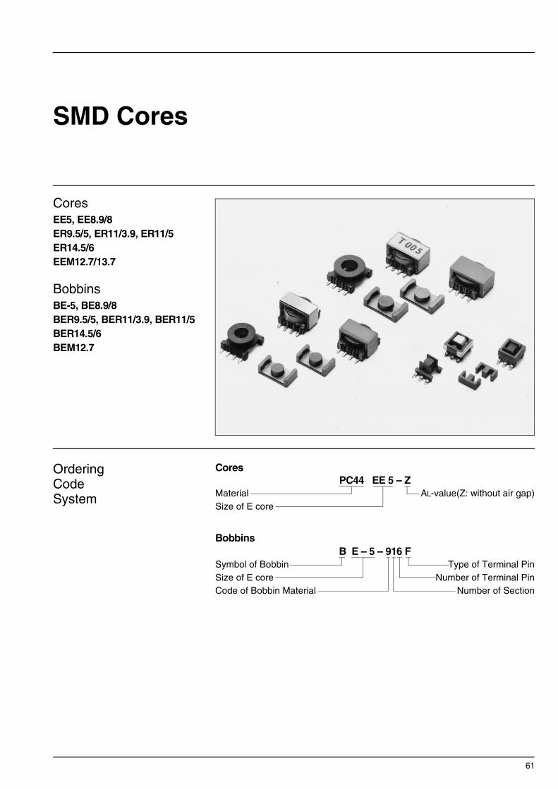
61
SMD Cores
CoresEE5, EE8.9/8ER9.5/5, ER11/3.9, ER11/5ER14.5/6EEM12.7/13.7
BobbinsBE-5, BE8.9/8BER9.5/5, BER11/3.9, BER11/5BER14.5/6BEM12.7
OrderingCodeSystem
Cores
Bobbins
PC44 EE 5 – ZMaterialSize of E core
AL-value(Z: without air gap)
B E – 5 – 916 FSymbol of BobbinSize of E coreCode of Bobbin Material
Type of Terminal PinNumber of Terminal Pin
Number of Section

62
∗ Please see the next page additionally.
SMD Cores and Bobbins
∗ ∗ 8-pin is available (Part No. BER11/5-118GAFR).
Part No. TypeDimensions in
A 2B C1 C2 E F 2H
PC44EE5-Z 1 5.25±0.05.207±.002
5.3±0.1 .209±.004
1.35±0.05.053±.002
0.70±0.05.028±.002
1.95±0.05.077±.002
4.0 .157
PC44EE8.9/8-Z 1 8.86±0.20.349±.008
8.0±0.3 .315±.012
1.90±0.12.075±.005
1.91±0.20.075±.008
1.90±0.12.075±.008
4.5±0.3 .177±.012
PC44ER9.5/5-Z PC50ER9.5/5-Z 2 9.35±0.15
.368±.0064.9±0.1 .193±.004
3.4±0.1 .134±.004
4.9±0.1 .193±.004
3.35±0.15.132±.004
PC44ER11/3.9-ZPC50ER11/3.9-Z 2 10.83±0.18
.426±.0073.85±0.10 .152±.004
4.13±0.13.163±.005
5.9±0.1 .232±.004
2.10±0.15.083±.006
PC44ER11/5-ZPC50ER11/5-Z 2 10.83±0.18
.426±.0074.9±0.1 .193±.004
4.13±0.13.163±.005
5.9±0.1 .232±.004
3.15±0.15.124±.006
PC44ER14.5/6-ZPC50ER14.5/6-Z 2 14.5±0.2
.571±.0085.9±0.1 .232±.004
4.7±0.1 .185±.004
6.7±0.1 .264±.004
3.3±0.2 .130±.008
PC44EEM12.7/13.7-ZPC50EEM12.7/13.7-Z 3 12.75±0.25
.502±.01013.7±0.3 .539±.012
6.0±0.1 .236±.004
1.85±0.10.073±.004
1.7±0.1 .067±.004
3.30±0.15.130±.006
9.1±0.3 .358±.012
Part No. TypeDimensions in
mminches
A B C X Y Z
BE5-916F BE5-926F 1 3.5
.1382.3 .091
2.7 .106
7.85.309
5.2 .205
4.65.183
BE8.9/8-118GFR 2 4.5 .177
62.7 .016
3.1 .122
11.2.441
9.2 .362
4.75.187
BEM12.7-118GAFR 3 8.9 .350
6.9 .272
7.5 .295
16.7.657
12.8.504
4.9 .193
BER9.5/5-118GAFR 4 7.3 .287
4.45.175
2.15.085
11.5.452
8.6 .339
4.45.175
BER11/3.9-1110GAFR 4 8.5 .335
5.2 .205
1.05.041
12.45 .490
10.5.413
3.4 .134
BER11/5-1110GAFR∗∗ 4 8.5 .335
5.2 .205
1.95.077
12.2.480
10.5.413
4.70.185
BER14.5/6-1110GAFR 4 11.4.449
5.9 .232
2.0 .079
16.0.630
14.0.551
5.75.226
Cores
mminches
Bobbins
Z
Y
C
A
B
X
0.5
Pt
Type 1
Z
Y
C
A
B
7.5
4.1
8.0
X
Pt
Type 2
2.15
0.5
Pin layoutItem BE-5-916F
0.486.89
1.85
0.6
Pin layoutItem BE8.9/8-118GFR
0.5310.14
2.54
Dimensions in mm

63
∗ P
leas
e se
e th
e fo
rmer
pag
e ad
ditio
nally
.
∗ AL-value: 1kHz, 0.5mA, 100Ts
UL Grade: 94V-0, Material: F, G types are Phosphor bronze wire (Solder plated), GA type is Steel wire (Solder plated).Maximum number of turns N that can be wound on bobbins, see section of “Maximum number of Turns on Bobbins”.∗ Minimum thickness of bobbin inside which core is placed, including flanges.
Effective parameter Electrical characteristicsWt(g) Bobbin item
I1 I2 C1
(mm–1)Ae(mm2)
e(mm)
Ve(mm3)
AL-value (nH/N2)∗
Without air gap With air gap3.85.152 4.72 2.67 12.6 33.6 200 min. 0.2 BE-5-916F
5.08 min..200 min. 3.15 4.96 15.6 77.4 480±25% 0.6 BE8.9/8-118GFR
7.63±0.13 .300±.005
7.0 min..276 min. 1.68 8.47 14.2 120 610 min.
750±25% 63±5%100±7% 0.6 BER9.5/5-118GAFR
8.85±0.15.348±.006
7.9 min..311 min. 1.08 11.7 12.6 147 1040 min.
1100±25% 63±5%100±7% 0.8 BER11/3.9-1110GAFR
8.85±0.15.348±.006
7.9 min..311 min. 1.24 11.9 14.7 175 870 min.
960±25% 63±5%100±7% 1.0 BER11/5-1110GAFR
11.8±0.2 .465±.008
11.8±0.2 .465±.008 1.08 17.6 19.0 334 1280 min.
1150±25% 100±5%160±7% 1.8 BER14.5/6-1110GAFR
9.0 min..354 min. 2.28 12.0 27.3 328 820±25%
580±25% 40±5%63±7% 1.9 BEM12.7-118GAFR
ParameterWt(g)
Accessoryitemt∗ Pt×Pw Terminal W
D (mm)H
Aw(mm2)
w(mm)
Material(mm) pins
0.4 0.2×0.5 6 5.7 7.8 4.8
1.62 12.4Diallyl Phtalate
0.030.08
FE-5-A
0.2 0.2×0.6 6 9.3 11.34.8
2.79 14.4 FR Phenol 0.17 —
0.35 0.3×0.5 8 13.616.85.0
7.5 22.4 FR Phenol 0.31 FEM12.7/13.7-A
0.4 0.3×0.5 8 9.9 11.75.9
3.06 18.5 FR Phenol 0.16 FER9.5/5-A
0.4 0.25×0.7 1011.012.64.7
1.73 21.5 FR Phenol 0.21 FER11/3.9-A
0.4 0.3×0.5 1011.512.36.4
3.22 21.5 FR Phenol 0.21 FER11/5-A
0.4 0.3×0.8 1015.116.27.3
5.5 27.2 FR Phenol 0.55 FER14.5/6-A
2B
2H F
AI1E
E
C1
Type 1
2B
2H F
AI1øC
1
I2
Type 2
2B
2H
F
C2
AI1E
E
C1
Type 3
0.5
2.0
15.70.5
0.5
2.0
10.40.55
0.5
2.0
11.10.55
0.8
2.5
14.60.7
Pin layoutItem BEM12.7-118GAFR
Pin layoutItem BER9.5/5-118GAFR
Pin layoutItem BER11/5-1110GAFR& (BER11/3.9-1110GAFR)
Pin layoutItem BER14.5/6-1110GAFR
Dimensions in mm
H
W D
Z
XY
Pt
C
A
B
0.6
Type 3
Z
XY
Pt
øA
øB
C
Type 4

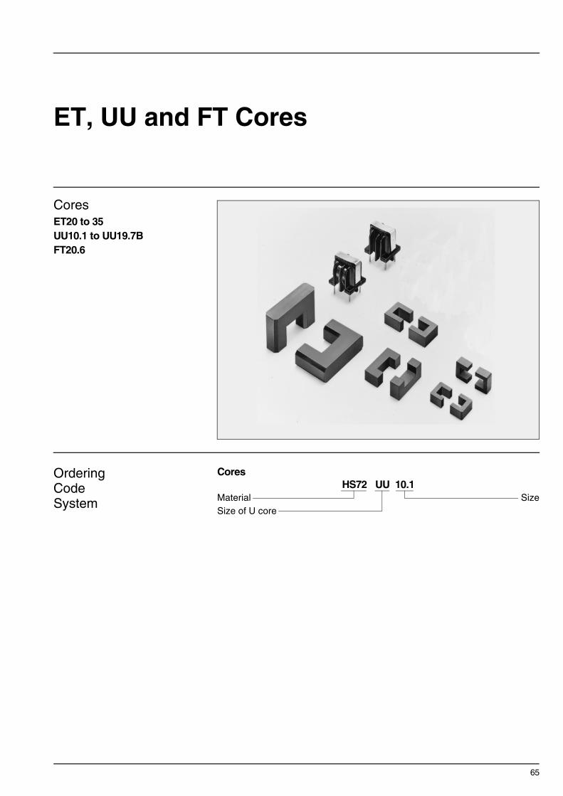
65
ET, UU and FT Cores
CoresET20 to 35UU10.1 to UU19.7BFT20.6
OrderingCodeSystem
CoresHS72 UU 10.1
MaterialSize of U core
Size

66
∗ Please see the next page additionally.
ET and UU Cores
∗ AL-value: 1kHz, 0.25A/m, 10Ts
∗ AL-value: 1kHz, 0.25A/m, 10Ts
Part No.AL-value∗
(nH/N2)
Dimensions inAe(mm2)
e(mm)A B C D E F
HS72ET20 3100 20.1±0.4 20.1±0.4 4.0±0.2 4.4±0.2 2.00±0.15 2.00±0.15
17.6 50.6.791±.016 .791±.016 .157±.008 .173±.008 .079±.006 .079±.006
HS72ET24 2600 24.2±0.5 24.2±0.5 4.0±0.2 4.0±0.3 2.40±0.15 2.40±0.15
17.8 61.0.953±.020 .953±.020 .157±.008 .157±.012 .094±.006 .094±.006
HS72ET28 3550 28.45±0.55 28.45±0.55 5.0±0.2 5.0±0.3 2.90±0.15 2.90±0.15
27.4 71.41.120±.022 1.120±.022 .197±.008 .197±.012 .114±.006 .114±.006
HS10ET28 4835±30% 28.45±0.55 28.45±0.55 5.0±0.2 5.0±0.3 2.90±0.15 2.90±0.15
27.4 71.41.120±.022 1.120±.022 .197±.008 .197±.012 .114±.006 .114±.006
HS72ET35 600035.3±0.6 35.3±0.6 7.5±0.3 7.5±0.3 4.0±0.2 4.0±0.2
58.6 86.71.390±.024 1.390±.024 .295±.012 .295±.012 .157±.008 .157±.008
Part No.AL-value∗
(nH/N2)
Dimensions inAe(mm2)
e(mm)A B C D E
HS72UU10.1 1005±25% 10.1±0.3 7.5±0.25 4.5±0.25 2.9±0.15 2.95±0.15
8.6 35.7.398±.012 .295±.010 .177±.010 .114±.006 .116±.006
HS72UU10.5 1500±25% 10.5±0.3 7.80±0.2 5.25±0.3 5.00±0.20 2.5±0.20
12.5 40.3.413±.012 .307±.008 .207±.012 .197±.008 .098±.008
HS72UU15.7 2600±25% 15.7±0.4 9.70±0.25 6.00±0.30 6.00±0.30 4.50
24.8 50.0.618±.016 .382±.010 .236±.012 .236±.012 .177
HS72UU19.7B 2650±25% 19.7±0.4 17.7±0.3 11.7±0.3 6.00±0.30 6.00±0.30
35.7 81.1.776±.016 .697±.012 .461±.012 .236±.012 .236±.012
ET Cores
F
A
FC
aa′′
a-a′
c
DEE
B
mminches
+40%–25%
+40%–25%
+40%–25%
+40%–25%
UU Cores
AE
E
D
Chamfer
C
B
mminches

67
∗ P
leas
e se
e th
e fo
rmer
pag
e ad
ditio
nally
.
FT Cores
∗ AL-value: 1kHz, 0.25A/m, 10Ts
Part No. AL-value∗
(nH/N2)Ae(mm2)
e(mm)
HS72FT20.6 2200 12.1 52.9
HS10FT20.6 2690±30% 12.1 52.9
FT Cores
2.3±0.15[.091±.006]
2.3±0.15[.091±.006]
15.7[.618]min.
20.6±0.3[.811±.012]
2.4
±0.2
[ .094
±.00
8]7.
35[ .2
89] m
in.
4.2
±0.2
[ .165
±.00
8]
14.1
±0.2
5[ .5
55±.
010]
4.6±0.2[.181±.008]
C
Dimensions in mm[inches]
+40%–30%


69
T Cores
Toroidal CoresFor Common mode choke
T14 to T44.5Material: HS52, HS72, HS10
For General UseT3.05 to T44.5Material: H5A, H5B2, H5C2,
H5C3, HP5
OrderingCodeSystem
CoresHS52 T 22 × 6.5 × 14
MaterialSymbol of Toroidal core
Inside DiameterThickness
Outside Diameter
TDK’s toroidal cores are available in a number of sizes.Therefore, by selecting the ferrite material which corresponds to the application, it is possible to design stable transformers, inductors, etc. to cover a wide band range.
FEATURES• Selection of core material to correspond to the application is possible as a result of
standard ferrite materials with µi=3300 to 15000. • Epoxy and paraxylylene insulation coating is available.APPLICATIONSPulse transformers, choke coils, filters, current sensors, EMI/RFI filters, balun trans-formers.

70
∗ Please see the next page additionally.
Toroidal CoresFor Common mode choke
Part No. JIS C 2569Dimensions in Effective parameter
øA øB C C1
(mm–1)Ae(mm2)
T14×7×8 14.0±0.3.551±.012
8.0±0.3 .315±.012
7.0±0.3 .276±.012
1.60 20.5
T18×10×10 FOR-18-10-1018.0±0.3 .709±.012
10.0±0.3 .394±.012
10.0±0.3 .394±.012
1.07 38.9
T16×8×1216.0±0.3 .630±.012
12.0±0.3 .472±.012
8.0±0.3 .315±.012
2.73 15.9
T20×10×12 FOR-20-10-1220.0±0.4 .787±.016
12.0±0.4 .472±.016
10.0±0.3 .394±.012
1.23 39.1
T22×6.5×1422.0±0.4 .866±.016
14.0±0.4 .551±.016
6.5±0.3 .256±.012
2.14 25.6
T25×13×15 25.0±0.4 .984±.016
15.0±0.4 .591±.016
13.0±0.3 .512±.012
0.946 63.6
T28×13×16 FOR-28-13-1628.0±0.4 1.102±.016
16.0±0.4 .630±.016
13.0±0.3 .512±.012
0.864 76.0
T31×8×1931.0±0.5 1.220±.020
19.0±0.5 .748±.020
8.0±0.3 .315±.012
1.60 47.1
T38×14×2238.0±0.5 1.496±.020
22.0±0.5 .866±.020
14.0±0.4 .551±.016
0.821 109
T44.5×13×30 FOR-45-13-3044.5±0.5 1.752±.020
30.0±0.5 1.181±.020
13.0±0.4 .512±.016
1.23 93
Cores
øA
øB
R or C
R or C
C
mminches

71
∗ P
leas
e se
e th
e fo
rmer
pag
e ad
ditio
nally
.
∗ AL-value: 100kHz, 100mV, 10Ts∗∗ AL-value: 100kHz, 10mV, 5Ts∗∗∗ AL-value: 10kHz, 10mV, 10Ts
AL-value (nH/N2)Wt(g) e
(mm)Ve(mm3)
R or C MaterialHS52∗ HS72∗∗ HS10∗∗∗
32.8 671 C0.5 3800±25% 5100±25% 6800±30% 3.4
41.5 1610 C0.5 6400±25% 8800±25% 10150±30% 8.3
43.4 689 C1.0 2500±25% 3400±25% 4500±30% 3.4
48.1 1880 C0.5 5600±25% 7600±25% 10000±30% 9.5
54.7 1400 C0.5 3200±25% 4400±25% 5750±30% 6.9
60.2 3830 C1.0 7300±25% 9900±25% 13000±30% 19
65.6 4990 C0.5 8000±25% 10700±25% 14200±30% 26
75.5 3550 C1.0 4300±25% 5800±25% 7700±30% 17
89.7 9800 C1.0 8400±25% 10700±25% — 50
114 10600 C0.5 5600±25% 7100±25% — 53
Can be coated with epoxy. If epoxy-coated products are desired, please suffix E to part No. when ordering.Ex. HS52 T22 × 6.5 × 12E∗
∗ Dielectric breakdown voltage 1000Vd.c. min.

72
∗ Please see the next page additionally.
Toroidal CoresFor General Use
Part No.(øA×C×øB)
Dimensions in Effective parameter
øA øB C C1
(mm–1)Ae e
(mm)(mm2)
T3.05×1.27×1.27 3.05.120
1.27.050
1.27.050
5.65 1.06 5.99
T4×1×2 4.00.157
2.00.079
1.00.039
9.07 0.961 8.71
T3.94×1.27×2.233.94.155
2.23.088
1.27.050
8.69 1.06 9.19
T4.83×1.27×2.294.83.190
2.29.090
1.27.050
6.63 1.54 10.2
T6×1.5×36.00.236
3.00.118
1.50.059
6.04 2.16 13.1
T5.84×1.52×3.055.84.230
3.05.120
1.52.060
6.36 2.05 13.0
T8×2×4 8.00.315
4.00.157
2.00.079
4.53 3.84 17.4
T10×2.5×5 10.0.394
5.00.197
2.50.098
3.63 6.01 21.8
T12×3×612.0.472
6.00.236
3.00.118
3.02 8.65 26.1
T14×3.5×714.0.551
7.00.276
3.50.138
2.59 11.8 30.5
T20×5×1020.0.787
10.0.394
5.00.197
1.81 24.0 43.6
T20×7.5×14.520.0.787
14.5.571
7.50.295
2.61 20.4 53.3
T28×13×16 28.01.102
16.0.630
13.0.512
0.864 76.0 65.6
T31×8×19 31.01.220
19.0.748
8.00.315
1.60 47.1 75.5
T38×14×2238.01.496
22.0.866
14.0.551
0.821 109 89.7
T44.5×13×3044.51.752
30.01.181
13.0.512
1.23 93.0 114
R
C
øA
øB
mminches

73
∗ P
leas
e se
e th
e fo
rmer
pag
e ad
ditio
nally
.
Test conditionsHP5, H5B2, H5C2 and H5C3: 10kHz, 10mV, 10TsPC40: 100kHz, 10mV, 10TsH5A: 50kHz, 10mV, 10Ts
AL-value (nH/N2)
HP5 H5B2 H5C3 PC40 H5A H5C2
1100±20% 1700±25% 3340±30%
670±20% 1000±25% 2000±30%
720±20% 1080±25% 2170±30%
950±20% 1400±25% 2840±30%
1000±20% 1500±25% 3000±30%
990±20% 1480±25% 2960±30%
1330±20% 2000±25% 4000±30%
1670±20% 2500±25% 5000±30%
1020±25% 1400±25% 3600±25%
1200±25% 1650±25% 4200±25%
1750±25% 2350±25% 6000±30%
1050±25% 1800±25% 4100±30%
14000±30%
7700±30%
13160±30%
10000±30%


Part II

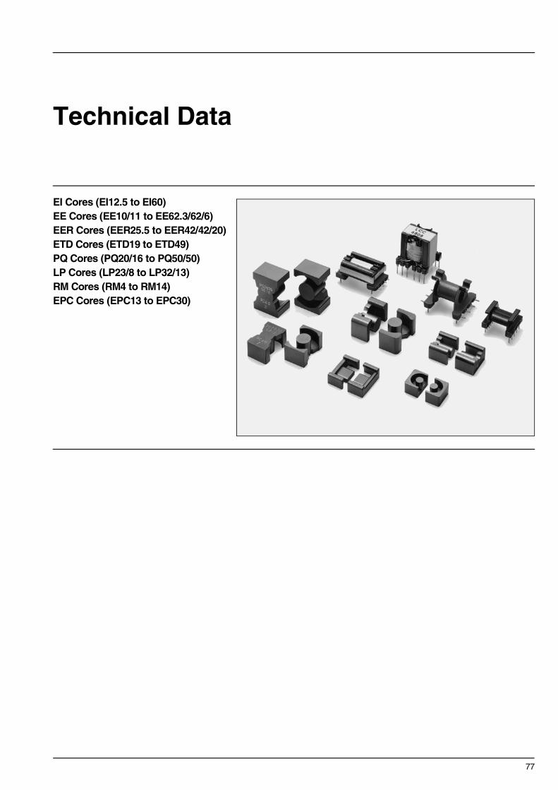
77
Technical Data
EI Cores (EI12.5 to EI60)EE Cores (EE10/11 to EE62.3/62/6)EER Cores (EER25.5 to EER42/42/20)ETD Cores (ETD19 to ETD49)PQ Cores (PQ20/16 to PQ50/50)LP Cores (LP23/8 to LP32/13)RM Cores (RM4 to RM14)EPC Cores (EPC13 to EPC30)

78
EI12.5 Cores(JIS FEI 12.5)
∗ Coil: ø0.2 2UEW 100Ts
NI limit vs. AL-value for AL-value vs. Air gap length for Temperature rise vs. Total loss forPC40EI12.5 gapped core (Typical) PC40EI12.5 core (Typical) EI12.5 core (Typical)
(Ambient temperature: 25°C)
Part No. AL-value (nH/N2)Core loss (W) at 100°C Calculated output power
(forward converter mode)100kHz, 200mT
PC40EI12.5-Z1200±25% (1kHz, 0.5mA)∗
2120 min. (100kHz, 200mT)0.12 max. 8.8W (100kHz)
ParameterCore factor C1 mm–1 1.48Effective magnetic path length e mm 21.3Effective cross-sectional area Ae mm2 14.4Effective core volume Ve mm3 308Cross-sectional center leg area Acp mm2 11.6Minimum cross-sectional area Acp min. mm2 10.8Cross-sectional winding area of core Acw mm2 17.3Weight (approx.) g 1.9
7.4±0.1
2.3 5.1±0.1
8.8
–0
1.6
1.6
12.4
±0.3
2.4
±0.1
4.85±0.15
12.4
±0.3
1.5±0.14.85±0.15
Dimensions in mm
Note: NI limit shows the point where the exciting current is 20% and 40% away from its extended linear part.
Measuring conditions • Coil: ø0.2 2UEW 100Ts • Frequency: 1kHz• Level: 0.5mA
Note: The temperature rise is measured in the room whose temperature and humidity are fixed to 25°C and 45(%)RH. respectively. (approx. 400×300×300cm)
101
102
NI l
imit(
AT
)
AL-value(nH/N2)102101
40%
Temperature: 100˚C
20%
101
102
AL-
valu
e(nH
/N2 )
Air gap length(mm)10.1
Center leg gap
Spacer gap
0
50
100
Tem
pera
ture
ris
e of
hot
spo
t ∆T
( ˚C
)
Total loss Pm(W)0 0.2 0.4 0.6 0.8 1
Measuring point
Coil
Core

79
EI16 Cores(JIS FEI 16)
∗ Coil: ø0.23 2UEW 100Ts
NI limit vs. AL-value for AL-value vs. Air gap length for Temperature rise vs. Total loss forPC40EI16 gapped core (Typical) PC40EI16 core (Typical) EI16 core (Typical)
(Ambient temperature: 25°C)
Part No. AL-value (nH/N2)Core loss (W) at 100°C Calculated output power
(forward converter mode)100kHz, 200mT
PC40EI16-Z1100±25% (1kHz, 0.5mA)∗
1750 min. (100kHz, 200mT)0.31 max. 29W (100kHz)
ParameterCore factor C1 mm–1 1.75Effective magnetic path length e mm 34.6Effective cross-sectional area Ae mm2 19.8Effective core volume Ve mm3 670Cross-sectional center leg area Acp mm2 19.2Minimum cross-sectional area Acp min. mm2 17.5Cross-sectional winding area of core Acw mm2 40.3Weight (approx.) g 3.3
12.2±0.2
2.0 10.2±0.2
11.6
–0
2.05
2.05
16.0
±0.3
4.0
±0.2
4.8±0.2 4.8±0.2
16.0
±0.3
2.0±0.2
Dimensions in mm
Note: NI limit shows the point where the exciting current is 20% and 40% away from its extended linear part.
Measuring conditions • Coil: ø0.23 2UEW 100Ts • Frequency: 1kHz• Level: 0.5mA
Note: The temperature rise is measured in the room whose temperature and humidity are fixed to 25°C and 45(%)RH. respectively. (approx. 400×300×300cm)
102
103
NI l
imit(
AT
)
AL-value(nH/N2)102101
40%
Temperature: 100˚C
20%
103
102
AL-
valu
e(nH
/N2 )
Air gap length(mm)10.1
Center leg gap
Spacer gap
0
50
100
Tem
pera
ture
ris
e of
hot
spo
t ∆T
( ˚C
)
Total loss Pm(W)0 0.5 1 1.5 2 2.5
Measuring point
Coil
Core

80
EI19 Cores
∗ Coil: ø0.23 2UEW 100Ts
NI limit vs. AL-value for AL-value vs. Air gap length for Temperature rise vs. Total loss forPC40EI19 gapped core (Typical) PC40EI19 core (Typical) EI19 core (Typical)
(Ambient temperature: 25°C)
Part No. AL-value (nH/N2)Core loss (W) at 100°C Calculated output power
(forward converter mode)100kHz, 200mT
PC40EI19-Z1400±25% (1kHz, 0.5mA)∗
1930 min. (100kHz, 200mT)0.42 max. 40W (100kHz)
ParameterCore factor C1 mm–1 1.65Effective magnetic path length e mm 39.6Effective cross-sectional area Ae mm2 24.0Effective core volume Ve mm3 950Cross-sectional center leg area Acp mm2 22.8Minimum cross-sectional area Acp min. mm2 21.1Cross-sectional winding area of core Acw mm2 55.5Weight (approx.) g 5.1
13.55±0.25
2.3 11.15±0.15
14.3
–0
2.75
2.75
20.0
±0.3
4.55
±0.1
5
5.0±0.2 5.0±0.2
20.0
±0.3
2.3±0.1
Dimensions in mm
Note: NI limit shows the point where the exciting current is 20% and 40% away from its extended linear part.
Measuring conditions • Coil: ø0.23 2UEW 100Ts • Frequency: 1kHz• Level: 0.5mA
Note: The temperature rise is measured in the room whose temperature and humidity are fixed to 25°C and 45(%)RH. respectively. (approx. 400×300×300cm)
Measuring point
Coil
Core
102
103
NI l
imit(
AT
)
AL-value(nH/N2)103102
40%
Temperature: 100˚C
20%
103
102
AL-
valu
e(nH
/N2 )
Air gap length(mm)10.1
Center leg gap
Spacer gap
0
50
100
Tem
pera
ture
ris
e of
hot
spo
t ∆T
( ˚C
)
Total loss Pm(W)0 0.5 1 1.5 2 2.5

81
EI22 Cores
∗ Coil: ø0.23 2UEW 100Ts
NI limit vs. AL-value for AL-value vs. Air gap length for Temperature rise vs. Total loss forPC40EI22 gapped core (Typical) PC40EI22 core (Typical) EI22 core (Typical)
(Ambient temperature: 25°C)
Part No. AL-value (nH/N2)Core loss (W) at 100°C Calculated output power
(forward converter mode)100kHz, 200mT
PC40EI22-Z2400±25% (1kHz, 0.5mA)∗
3360 min. (100kHz, 200mT)0.60 max. 33W (100kHz)
ParameterCore factor C1 mm–1 0.936Effective magnetic path length e mm 39.3Effective cross-sectional area Ae mm2 42.0Effective core volume Ve mm3 1630Cross-sectional center leg area Acp mm2 33.1Minimum cross-sectional area Acp min. mm2 30.3Cross-sectional winding area of core Acw mm2 38.2Weight (approx.) g 9.8
14.55±0.25
4.0 10.55±0.25
13.0
–0
4.5
4.5
22.0
±0.3
5.75
±0.2
55.75±0.25 5.75±0.25
22.0
±0.3
4.5±0.2
Dimensions in mm
Note: NI limit shows the point where the exciting current is 20% and 40% away from its extended linear part.
Measuring conditions • Coil: ø0.23 2UEW 100Ts • Frequency: 1kHz• Level: 0.5mA
Note: The temperature rise is measured in the room whose temperature and humidity are fixed to 25°C and 45(%)RH. respectively. (approx. 400×300×300cm)
Measuring point
Coil
Core
102
103
NI l
imit(
AT
)
AL-value(nH/N2)103102
40%
Temperature: 100˚C
20%
103
102
AL-
valu
e(nH
/N2 )
Air gap length(mm)10.1
Center leg gap
Spacer gap
0
50
100
Tem
pera
ture
ris
e of
hot
spo
t ∆T
( ˚C
)
Total loss Pm(W)0 0.5 1 1.5 2 2.5

82
EI22/19/6 Cores(JIS FEI 22)
∗ Coil: ø0.23 2UEW 100Ts
NI limit vs. AL-value for AL-value vs. Air gap length for Temperature rise vs. Total loss forPC40EI22/19/6 gapped core (Typical) PC40EI22/19/6 core (Typical) EI22/19/6 core (Typical)
(Ambient temperature: 25°C)
Part No. AL-value (nH/N2)Core loss (W) at 100°C Calculated output power
(forward converter mode)100kHz, 200mT
PC40EI22/19/6-Z2000±25% (1kHz, 0.5mA)∗
2780 min. (100kHz, 200mT)0.64 max. 48W (100kHz)
ParameterCore factor C1 mm–1 1.13Effective magnetic path length e mm 41.8Effective cross-sectional area Ae mm2 37.0Effective core volume Ve mm3 1550Cross-sectional center leg area Acp mm2 33.1Minimum cross-sectional area Acp min. mm2 30.3Cross-sectional winding area of core Acw mm2 54.8Weight (approx.) g 8.5
14.7±0.2
4.0 10.7±0.2
15.7
5–
03.
03.
0
22.0
±0.4
5.75
±0.2
5
5.75±0.25 5.75±0.25
22.0
±0.4
4.0±0.2
Dimensions in mm
Note: NI limit shows the point where the exciting current is 20% and 40% away from its extended linear part.
Measuring conditions • Coil: ø0.23 2UEW 100Ts • Frequency: 1kHz• Level: 0.5mA
Note: The temperature rise is measured in the room whose temperature and humidity are fixed to 25°C and 45(%)RH. respectively. (approx. 400×300×300cm)
Measuring point
Coil
Core
102
103
NI l
imit(
AT
)
AL-value(nH/N2)103102
40%
Temperature: 100˚C
20%
103
102
AL-
valu
e(nH
/N2 )
Air gap length(mm)10.1
Center leg gap
Spacer gap
0
50
100
Tem
pera
ture
ris
e of
hot
spo
t ∆T
( ˚C
)
Total loss Pm(W)0 0.5 1 1.5 2 2.5

83
EI25 Cores
∗ Coil: ø0.35 2UEW 100Ts
NI limit vs. AL-value for AL-value vs. Air gap length for Temperature rise vs. Total loss forPC40EI25 gapped core (Typical) PC40EI25 core (Typical) EI25 core (Typical)
(Ambient temperature: 25°C)
Part No. AL-value (nH/N2)Core loss (W) at 100°C Calculated output power
(forward converter mode)100kHz, 200mT
PC40EI25-Z2140±25% (1kHz, 0.5mA)∗
2950 min. (100kHz, 200mT)0.79 max. 68W (100kHz)
ParameterCore factor C1 mm–1 1.15Effective magnetic path length e mm 47.0Effective cross-sectional area Ae mm2 41.0Effective core volume Ve mm3 1930Cross-sectional center leg area Acp mm2 43.9Minimum cross-sectional area Acp min. mm2 40.3Cross-sectional winding area of core Acw mm2 77.2Weight (approx.) g 9.8
15.55±0.25
3.2 12.35±0.25
19.0
–0
3.0
3.0
25.3
±0.5
6.5
±0.3
6.75±0.25 6.75±0.25
25.3
±0.5
2.7±0.2
Dimensions in mm
Note: NI limit shows the point where the exciting current is 20% and 40% away from its extended linear part.
Measuring conditions • Coil: ø0.35 2UEW 100Ts • Frequency: 1kHz• Level: 0.5mA
Note: The temperature rise is measured in the room whose temperature and humidity are fixed to 25°C and 45(%)RH. respectively. (approx. 400×300×300cm)
Measuring point
Coil
Core
102
103
NI l
imit(
AT
)
AL-value(nH/N2)103102
40%
Temperature: 100˚C
20%
103
102
AL-
valu
e(nH
/N2 )
Air gap length(mm)10.1
Spacer gap
Center leg gap
0
50
100
Tem
pera
ture
ris
e of
hot
spo
t ∆T
( ˚C
)
Total loss Pm(W)0 0.5 1 1.5 2 2.5

84
EI28 Cores(JIS FEI 28)
∗ Coil: ø0.35 2UEW 100Ts
NI limit vs. AL-value for AL-value vs. Air gap length for Temperature rise vs. Total loss forPC40EI28 gapped core (Typical) PC40EI28 core (Typical) EI28 core (Typical)
(Ambient temperature: 25°C)
Part No. AL-value (nH/N2)Core loss (W) at 100°C Calculated output power
(forward converter mode)100kHz, 200mT
PC40EI28-Z4300±25% (1kHz, 0.5mA)∗
6060 min. (100kHz, 200mT)1.65 max. 107W (100kHz)
ParameterCore factor C1 mm–1 0.560Effective magnetic path length e mm 48.2Effective cross-sectional area Ae mm2 86.0Effective core volume Ve mm3 4150Cross-sectional center leg area Acp mm2 76.3Minimum cross-sectional area Acp min. mm2 71.8Cross-sectional winding area of core Acw mm2 69.8Weight (approx.) g 22
16.75±0.25
4.512.25±0.25
18.4
–0
4.5
4.5
28.0
7.2
±0.3
10.6±0.2 10.7±0.3
28.0
±0.5
3.5±0.3
Dimensions in mm
+0.
7–0
.5
Note: NI limit shows the point where the exciting current is 20% and 40% away from its extended linear part.
Measuring conditions • Coil: ø0.35 2UEW 100Ts • Frequency: 1kHz• Level: 0.5mA
Note: The temperature rise is measured in the room whose temperature and humidity are fixed to 25°C and 45(%)RH. respectively. (approx. 400×300×300cm)
Measuring point
Coil
Core
102
103
NI l
imit(
AT
)
AL-value(nH/N2)103102
40%
Temperature: 100˚C
20%
103
102
AL-
valu
e(nH
/N2 )
Air gap length(mm)10.1
Center leg gap
Spacer gap
0
50
100
Tem
pera
ture
ris
e of
hot
spo
t ∆T
( ˚C
)
Total loss Pm(W)0 0.5 1 1.5 2 2.5

85
EI30 Cores(JIS FEI 30)
∗ Coil: ø0.35 2UEW 100Ts
NI limit vs. AL-value for AL-value vs. Air gap length for Temperature rise vs. Total loss forPC40EI30 gapped core (Typical) PC40EI30 core (Typical) EI30 core (Typical)
(Ambient temperature: 25°C)
Part No. AL-value (nH/N2)Core loss (W) at 100°C Calculated output power
(forward converter mode)100kHz, 200mT
PC40EI30-Z4690±25% (1kHz, 0.5mA)∗
6500 min. (100kHz, 200mT)3.1 max. 155W (100kHz)
ParameterCore factor C1 mm–1 0.522Effective magnetic path length e mm 58.0Effective cross-sectional area Ae mm2 111Effective core volume Ve mm3 6440Cross-sectional center leg area Acp mm2 114Minimum cross-sectional area Acp min. mm2 108Cross-sectional winding area of core Acw mm2 75.6Weight (approx.) g 34
21.25±0.25
5.0 16.25±0.25
19.7
–0
5.0
5.0
30.0
10.7
±0.3
10.7±0.3 10.7±0.3
Dimensions in mm
30.0
±0.4
5.5±0.2
+0.
7–0
.4
Note: NI limit shows the point where the exciting current is 20% and 40% away from its extended linear part.
Measuring conditions • Coil: ø0.35 2UEW 100Ts • Frequency: 1kHz• Level: 0.5mA
Note: The temperature rise is measured in the room whose temperature and humidity are fixed to 25°C and 45(%)RH. respectively. (approx. 400×300×300cm)
Measuring point
Coil
Core
102
103
NI l
imit(
AT
)
AL-value(nH/N2)103102
40%
Temperature: 100˚C
20%
103
102
AL-
valu
e(nH
/N2 )
Air gap length(mm)10.1
Spacer gap
Center leg gap
0
50
100
Tem
pera
ture
ris
e of
hot
spo
t ∆T
( ˚C
)
Total loss Pm(W)0 1 2 3 4 5
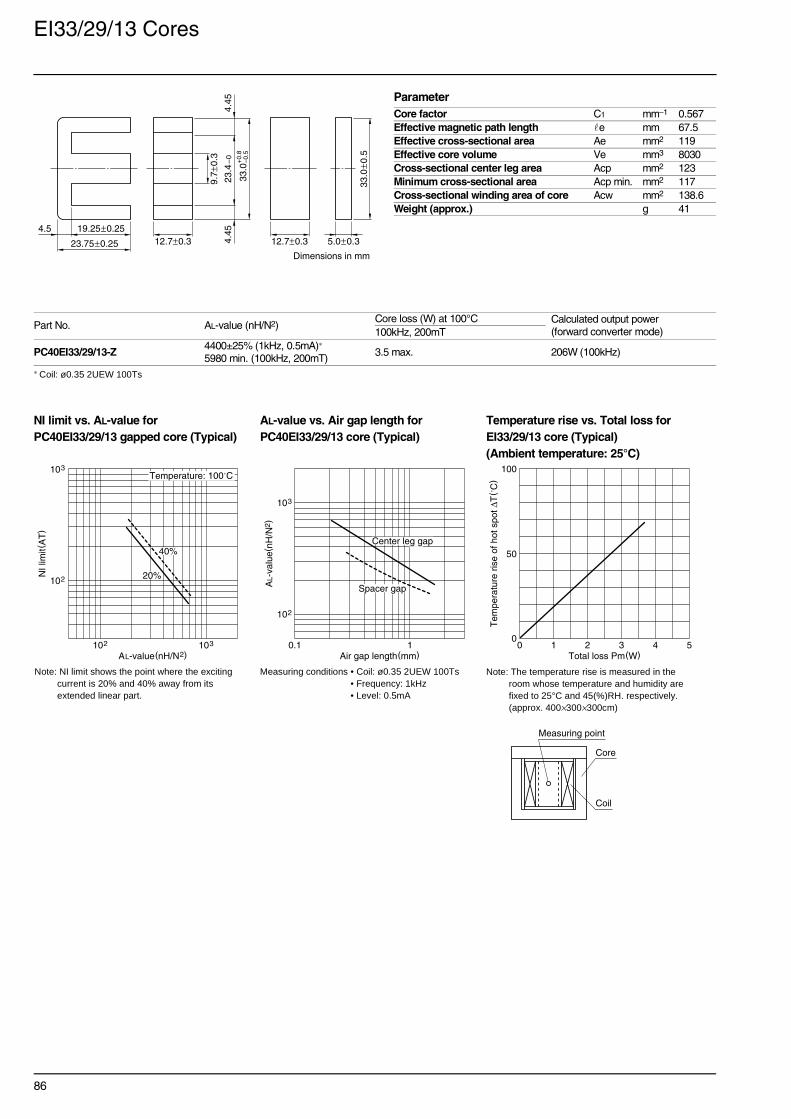
86
EI33/29/13 Cores
∗ Coil: ø0.35 2UEW 100Ts
NI limit vs. AL-value for AL-value vs. Air gap length for Temperature rise vs. Total loss forPC40EI33/29/13 gapped core (Typical) PC40EI33/29/13 core (Typical) EI33/29/13 core (Typical)
(Ambient temperature: 25°C)
Part No. AL-value (nH/N2)Core loss (W) at 100°C Calculated output power
(forward converter mode)100kHz, 200mT
PC40EI33/29/13-Z4400±25% (1kHz, 0.5mA)∗
5980 min. (100kHz, 200mT)3.5 max. 206W (100kHz)
ParameterCore factor C1 mm–1 0.567Effective magnetic path length e mm 67.5Effective cross-sectional area Ae mm2 119Effective core volume Ve mm3 8030Cross-sectional center leg area Acp mm2 123Minimum cross-sectional area Acp min. mm2 117Cross-sectional winding area of core Acw mm2 138.6Weight (approx.) g 41
23.75±0.25
4.5 19.25±0.2523
.4–
04.
454.
45
33.0
9.7±
0.3
12.7±0.3 12.7±0.3
Dimensions in mm
33.0
±0.5
5.0±0.3+
0.8
–0.5
Note: NI limit shows the point where the exciting current is 20% and 40% away from its extended linear part.
Measuring conditions • Coil: ø0.35 2UEW 100Ts • Frequency: 1kHz• Level: 0.5mA
Note: The temperature rise is measured in the room whose temperature and humidity are fixed to 25°C and 45(%)RH. respectively. (approx. 400×300×300cm)
Measuring point
Coil
Core
102
103
NI l
imit(
AT
)
AL-value(nH/N2)103102
40%
Temperature: 100˚C
20%
103
102
AL-
valu
e(nH
/N2 )
Air gap length(mm)10.1
Center leg gap
Spacer gap
0
50
100
Tem
pera
ture
ris
e of
hot
spo
t ∆T
( ˚C
)
Total loss Pm(W)0 1 2 3 4 5

87
EI35 Cores(JIS FEI 35)
∗ Coil: ø0.35 2UEW 100Ts
NI limit vs. AL-value for AL-value vs. Air gap length for Temperature rise vs. Total loss forPC40EI35 gapped core (Typical) PC40EI35 core (Typical) EI35 core (Typical)
(Ambient temperature: 25°C)
Part No. AL-value (nH/N2)Core loss (W) at 100°C Calculated output power
(forward converter mode)100kHz, 200mT
PC40EI35-Z3800±25% (1kHz, 0.5mA)∗
5110 min. (100kHz, 200mT)2.85 max. 218W (100kHz)
ParameterCore factor C1 mm–1 0.664Effective magnetic path length e mm 67.1Effective cross-sectional area Ae mm2 101Effective core volume Ve mm3 6780Cross-sectional center leg area Acp mm2 100Minimum cross-sectional area Acp min. mm2 94.1Cross-sectional winding area of core Acw mm2 131.6Weight (approx.) g 36
24.35±0.15
6.1 18.25±0.15
24.5
–0
5.0
5.0
35.0
±0.5
10.0
±0.3
10.0±0.3 10.0±0.3
Dimensions in mm
35.0
±0.5
4.6±0.3
Note: NI limit shows the point where the exciting current is 20% and 40% away from its extended linear part.
Measuring conditions • Coil: ø0.35 2UEW 100Ts • Frequency: 1kHz• Level: 0.5mA
Note: The temperature rise is measured in the room whose temperature and humidity are fixed to 25°C and 45(%)RH. respectively. (approx. 400×300×300cm)
Measuring point
Coil
Core
102
103
NI l
imit(
AT
)
AL-value(nH/N2)103102
40%
Temperature: 100˚C
20%
103
102
AL-
valu
e(nH
/N2 )
Air gap length(mm)10.1
Center leg gap
Spacer gap
0
50
100
Tem
pera
ture
ris
e of
hot
spo
t ∆T
( ˚C
)
Total loss Pm(W)0 1 2 3 4 5

88
EI40 Cores(JIS FEI 40)
∗ Coil: ø0.35 2UEW 100Ts
NI limit vs. AL-value for AL-value vs. Air gap length for Temperature rise vs. Total loss forPC40EI40 gapped core (Typical) PC40EI40 core (Typical) EI40 core (Typical)
(Ambient temperature: 25°C)
Part No. AL-value (nH/N2)Core loss (W) at 100°C Calculated output power
(forward converter mode)100kHz, 200mT
PC40EI40-Z4860±25% (1kHz, 0.5mA)∗
6520 min. (100kHz, 200mT)4.8 max. 348W (100kHz)
ParameterCore factor C1 mm–1 0.520Effective magnetic path length e mm 77.0Effective cross-sectional area Ae mm2 148Effective core volume Ve mm3 11400Cross-sectional center leg area Acp mm2 136Minimum cross-sectional area Acp min. mm2 128Cross-sectional winding area of core Acw mm2 160.5Weight (approx.) g 60
27.25±0.25
7.0 20.25±0.25
27.2
–0
6.2
6.2
40.0
±0.5
11.6
5±0
.35
11.65±0.35 11.65±0.35
Dimensions in mm
40.0
±0.5
7.5±0.3
Note: NI limit shows the point where the exciting current is 20% and 40% away from its extended linear part.
Measuring conditions • Coil: ø0.35 2UEW 100Ts • Frequency: 1kHz• Level: 0.5mA
Note: The temperature rise is measured in the room whose temperature and humidity are fixed to 25°C and 45(%)RH. respectively. (approx. 400×300×300cm)
Measuring point
Coil
Core
102
103
NI l
imit(
AT
)
AL-value(nH/N2)103102
40%
Temperature: 100˚C
20%
103
102
AL-
valu
e(nH
/N2 )
Air gap length(mm)10.1
Center leg gap
Spacer gap
0
50
100
Tem
pera
ture
ris
e of
hot
spo
t ∆T
( ˚C
)
Total loss Pm(W)0 2 4 6 8 10

89
EI50 Cores(JIS FEI 50)
∗ Coil: ø0.35 2UEW 100Ts
NI limit vs. AL-value for AL-value vs. Air gap length for Temperature rise vs. Total loss forPC40EI50 gapped core (Typical) PC40EI50 core (Typical) EI50 core (Typical)
(Ambient temperature: 25°C)
Part No. AL-value (nH/N2)Core loss (W) at 100°C Calculated output power
(forward converter mode)100kHz, 200mT
PC40EI50-Z6110±25% (1kHz, 0.5mA)∗
8300 min. (100kHz, 200mT)9.2 max. 508W (100kHz)
ParameterCore factor C1 mm–1 0.409Effective magnetic path length e mm 94.0Effective cross-sectional area Ae mm2 230Effective core volume Ve mm3 21620Cross-sectional center leg area Acp mm2 213Minimum cross-sectional area Acp min. mm2 202Cross-sectional winding area of core Acw mm2 246.3Weight (approx.) g 115
33.35±0.35
8.5 24.75±0.25
33.5
–0
7.7
7.7
50.0
14.6
±0.4
14.6±0.4 14.6±0.4
Dimensions in mm
50.0
±0.7
9.0±0.3
+1.
2–0
.7
Note: NI limit shows the point where the exciting current is 20% and 40% away from its extended linear part.
Measuring conditions • Coil: ø0.35 2UEW 100Ts • Frequency: 1kHz• Level: 0.5mA
Note: The temperature rise is measured in the room whose temperature and humidity are fixed to 25°C and 45(%)RH. respectively. (approx. 400×300×300cm)
Measuring point
Coil
Core
102
103
NI l
imit(
AT
)
AL-value(nH/N2)103102
40%
20%
Temperature: 100˚C
102
103
AL-
valu
e(nH
/N2 )
Air gap length(mm)0.1 1
Center leg gap
Spacer gap
0
50
100
Tem
pera
ture
ris
e of
hot
spo
t ∆T
( ˚C
)
Total loss Pm(W)0 2 4 6 8 10
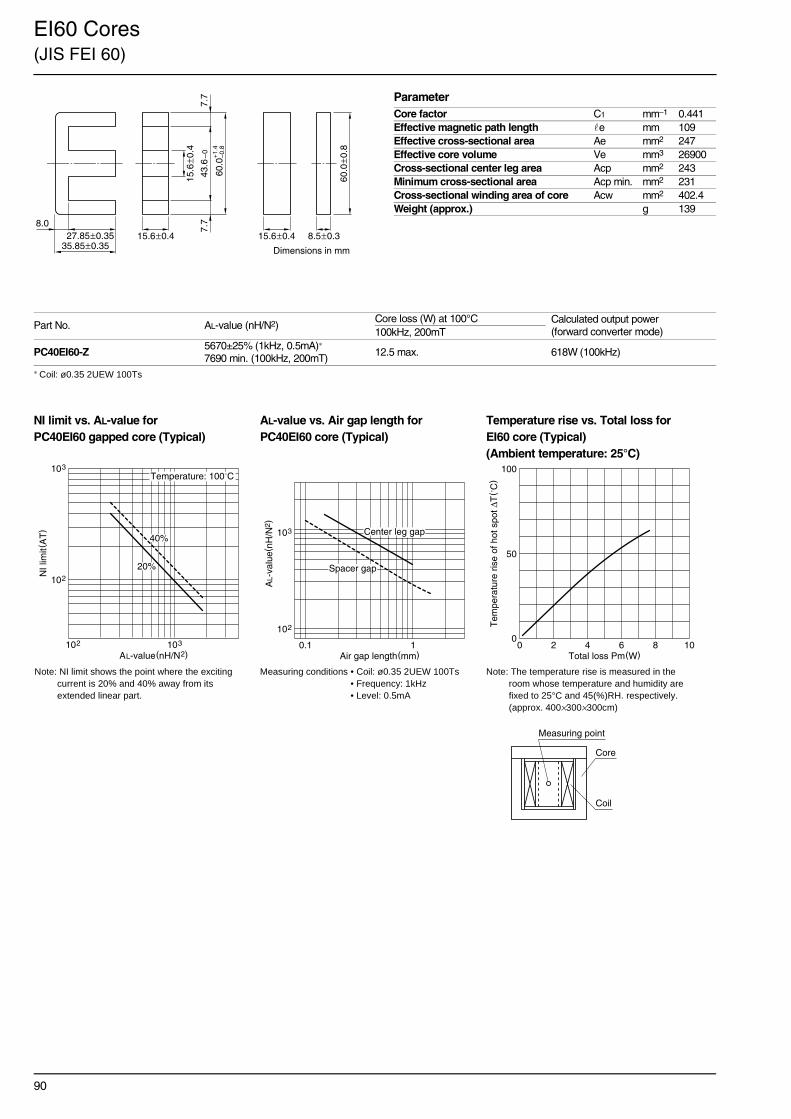
90
EI60 Cores(JIS FEI 60)
∗ Coil: ø0.35 2UEW 100Ts
NI limit vs. AL-value for AL-value vs. Air gap length for Temperature rise vs. Total loss forPC40EI60 gapped core (Typical) PC40EI60 core (Typical) EI60 core (Typical)
(Ambient temperature: 25°C)
Part No. AL-value (nH/N2)Core loss (W) at 100°C Calculated output power
(forward converter mode)100kHz, 200mT
PC40EI60-Z5670±25% (1kHz, 0.5mA)∗
7690 min. (100kHz, 200mT)12.5 max. 618W (100kHz)
ParameterCore factor C1 mm–1 0.441Effective magnetic path length e mm 109Effective cross-sectional area Ae mm2 247Effective core volume Ve mm3 26900Cross-sectional center leg area Acp mm2 243Minimum cross-sectional area Acp min. mm2 231Cross-sectional winding area of core Acw mm2 402.4Weight (approx.) g 139
35.85±0.35
8.027.85±0.35
43.6
–0
7.7
7.7
60.0
15.6
±0.4
15.6±0.4 15.6±0.4
Dimensions in mm
60.0
±0.8
8.5±0.3
+1.
4–0
.8
Note: NI limit shows the point where the exciting current is 20% and 40% away from its extended linear part.
Measuring conditions • Coil: ø0.35 2UEW 100Ts • Frequency: 1kHz• Level: 0.5mA
Note: The temperature rise is measured in the room whose temperature and humidity are fixed to 25°C and 45(%)RH. respectively. (approx. 400×300×300cm)
Measuring point
Coil
Core
102
103
NI l
imit(
AT
)
AL-value(nH/N2)103102
40%
20%
Temperature: 100˚C
102
103
AL-
valu
e(nH
/N2 )
Air gap length(mm)0.1 1
Center leg gap
Spacer gap
0
50
100
Tem
pera
ture
ris
e of
hot
spo
t ∆T
( ˚C
)
Total loss Pm(W)0 2 4 6 8 10
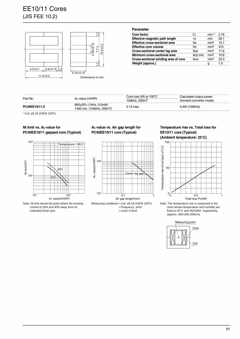
91
EE10/11 Cores(JIS FEE 10.2)
∗ Coil: ø0.18 2UEW 100Ts
NI limit vs. AL-value for AL-value vs. Air gap length for Temperature rise vs. Total loss forPC40EE10/11 gapped core (Typical) PC40EE10/11 core (Typical) EE10/11 core (Typical)
(Ambient temperature: 25°C)
Part No. AL-value (nH/N2)Core loss (W) at 100°C Calculated output power
(forward converter mode)100kHz, 200mT
PC40EE10/11-Z850±25% (1kHz, 0.5mA)∗
1450 min. (100kHz, 200mT)0.14 max. 9.4W (100kHz)
ParameterCore factor C1 mm–1 2.16Effective magnetic path length e mm 26.1Effective cross-sectional area Ae mm2 12.1Effective core volume Ve mm3 315Cross-sectional center leg area Acp mm2 11.6Minimum cross-sectional area Acp min. mm2 10.6Cross-sectional winding area of core Acw mm2 23.3Weight (approx.) g 1.5
11.0±0.2
5.5±0.1 4.2±0.15 1.3
7.7–
01.
11.
1
10.2
±0.2
2.45
±0.1
5
4.75±0.15
Dimensions in mm
Note: NI limit shows the point where the exciting current is 20% and 40% away from its extended linear part.
Measuring conditions • Coil: ø0.18 2UEW 100Ts • Frequency: 1kHz• Level: 0.5mA
Note: The temperature rise is measured in the room whose temperature and humidity are fixed to 25°C and 45(%)RH. respectively. (approx. 400×300×300cm)
102
103
NI l
imit(
AT
)
AL-value(nH/N2)102101
40%
20%
Temperature: 100˚C
101
102
AL-
valu
e(nH
/N2 )
Air gap length(mm)10.1
Center leg gap
0
50
100
Tem
pera
ture
ris
e of
hot
spo
t ∆T
( ˚C
)
Total loss Pm(W)0 10.5
Measuring point
Coil
Core

92
EE13 Cores
∗ Coil: ø0.18 2UEW 100Ts
NI limit vs. AL-value for AL-value vs. Air gap length for Temperature rise vs. Total loss forPC40EE13 gapped core (Typical) PC40EE13 core (Typical) EE13 core (Typical)
(Ambient temperature: 25°C)
Part No. AL-value (nH/N2)Core loss (W) at 100°C Calculated output power
(forward converter mode)100kHz, 200mT
PC40EE13-Z1130±25% (1kHz, 0.5mA)∗
1770 min. (100kHz, 200mT)0.235 max. 17W (100kHz)
ParameterCore factor C1 mm–1 1.77Effective magnetic path length e mm 30.2Effective cross-sectional area Ae mm2 17.1Effective core volume Ve mm3 517Cross-sectional center leg area Acp mm2 16.9Minimum cross-sectional area Acp min. mm2 15.6Cross-sectional winding area of core Acw mm2 34.3Weight (approx.) g 2.7
12.0±0.3
6.0±0.15 4.6±0.1 1.4
10.0
–0
1.4
1.4
13.0
±0.2
2.75
±0.1
56.15±0.15
Dimensions in mm
Note: NI limit shows the point where the exciting current is 20% and 40% away from its extended linear part.
Measuring conditions • Coil: ø0.18 2UEW 100Ts • Frequency: 1kHz• Level: 0.5mA
Note: The temperature rise is measured in the room whose temperature and humidity are fixed to 25°C and 45(%)RH. respectively. (approx. 400×300×300cm)
102
103
NI l
imit(
AT
)
AL-value(nH/N2)102101
40%
20%
Temperature: 100˚C
101
102
AL-
valu
e(nH
/N2 )
Air gap length(mm)10.1
Center leg gap
0
50
100
Tem
pera
ture
ris
e of
hot
spo
t ∆T
( ˚C
)
Total loss Pm(W)0 10.5
Measuring point
Coil
Core

93
SEE16 Cores
∗ Coil: ø0.23 2UEW 100Ts
NI limit vs. AL-value for AL-value vs. Air gap length for Temperature rise vs. Total loss forPC40SEE16 gapped core (Typical) PC40SEE16 core (Typical) SEE16 core (Typical)
(Ambient temperature: 25°C)
Part No. AL-value (nH/N2)Core loss (W) at 100°C Calculated output power
(forward converter mode)100kHz, 200mT
PC40SEE16-Z1240±25% (1kHz, 0.5mA)∗
1850 min. (100kHz, 200mT)0.37 max. 32W (100kHz)
ParameterCore factor C1 mm–1 1.69Effective magnetic path length e mm 36.6Effective cross-sectional area Ae mm2 21.7Effective core volume Ve mm3 795Cross-sectional center leg area Acp mm2 21.6Minimum cross-sectional area Acp min. mm2 19.8Cross-sectional winding area of core Acw mm2 52.9Weight (approx.) g 4.1
14.3±0.3
7.15±0.15 5.5±0.1 1.6
12.5
–0
1.6
1.6
16.0
±0.3
3.18
±0.1
8
6.8±0.2
Dimensions in mm
Note: NI limit shows the point where the exciting current is 20% and 40% away from its extended linear part.
Measuring conditions • Coil: ø0.23 2UEW 100Ts • Frequency: 1kHz• Level: 0.5mA
Note: The temperature rise is measured in the room whose temperature and humidity are fixed to 25°C and 45(%)RH. respectively. (approx. 400×300×300cm)
Measuring point
Coil
Core
102
103
NI l
imit(
AT
)
AL-value(nH/N2)102101
40%
20%
Temperature: 100˚C
101
102
AL-
valu
e(nH
/N2 )
Air gap length(mm)10.1
Center leg gap
0
50
100
Tem
pera
ture
ris
e of
hot
spo
t ∆T
( ˚C
)
Total loss Pm(W)0 2.521.510.5

94
EE20/20/5 Cores(DIN 41295)
∗ Coil: ø0.23 2UEW 100Ts
NI limit vs. AL-value for AL-value vs. Air gap length for Temperature rise vs. Total loss forPC40EE20/20/5 gapped core (Typical) PC40EE20/20/5 core (Typical) EE20/20/5 core (Typical)
(Ambient temperature: 25°C)
Part No. AL-value (nH/N2)Core loss (W) at 100°C Calculated output power
(forward converter mode)100kHz, 200mT
PC40EE20/20/5-Z1400±25% (1kHz, 0.5mA)∗
2270 min. (100kHz, 200mT)0.51 max. 41W (100kHz)
ParameterCore factor C1 mm–1 1.38Effective magnetic path length e mm 43.0Effective cross-sectional area Ae mm2 31.0Effective core volume Ve mm3 1340Cross-sectional center leg area Acp mm2 25.5Minimum cross-sectional area Acp min. mm2 23.5Cross-sectional winding area of core Acw mm2 41.3Weight (approx.) g 7.5
Based on DIN 41295.
20.0±0.4
10.0±0.2 6.5±0.2 3.512
.8–
03.
533.
53
20.1
5±0
.55
5.0
±0.2
5.1±0.2
Dimensions in mm
Note: NI limit shows the point where the exciting current is 20% and 40% away from its extended linear part.
Measuring conditions • Coil: ø0.23 2UEW 100Ts • Frequency: 1kHz• Level: 0.5mA
Note: The temperature rise is measured in the room whose temperature and humidity are fixed to 25°C and 45(%)RH. respectively. (approx. 400×300×300cm)
103
102
103102
NI l
imit(
AT
)
AL-value(nH/N2)
Temperature: 100˚C
40%
20% AL-
valu
e(nH
/N2 )
Air gap length(mm)
103
102
10.1
Center leg gap
0
50
100
Tem
pera
ture
ris
e of
hot
spo
t ∆T
( ˚C
)
Total loss Pm(W)0 2.521.510.5
Measuring point
Coil
Core

95
EE25/19 Cores(EE-24/25)
∗ Coil: ø0.23 2UEW 100Ts
NI limit vs. AL-value for AL-value vs. Air gap length for Temperature rise vs. Total loss forPC40EE25/19 gapped core (Typical) PC40EE25/19 core (Typical) EE25/19 core (Typical)
(Ambient temperature: 25°C)
Part No. AL-value (nH/N2)Core loss (W) at 100°C Calculated output power
(forward converter mode)100kHz, 200mT
PC40EE25/19-Z2000±25% (1kHz, 0.5mA)∗
2570 min. (100kHz, 200mT)0.86 max. 70W (100kHz)
ParameterCore factor C1 mm–1 1.22Effective magnetic path length e mm 48.7Effective cross-sectional area Ae mm2 40.0Effective core volume Ve mm3 1950Cross-sectional center leg area Acp mm2 39.9Minimum cross-sectional area Acp min. mm2 37.2Cross-sectional winding area of core Acw mm2 79.0Weight (approx.) g 9.1
Based on standard U. S. lamination size.
18.92±0.38
9.46±0.196.41±0.19
3.05
18.5
5–0
3.11
3.11
25.4
±0.5
6.35
±0.2
56.29±0.19
Dimensions in mm
Note: NI limit shows the point where the exciting current is 20% and 40% away from its extended linear part.
Measuring conditions • Coil: ø0.23 2UEW 100Ts • Frequency: 1kHz• Level: 0.5mA
Note: The temperature rise is measured in the room whose temperature and humidity are fixed to 25°C and 45(%)RH. respectively. (approx. 400×300×300cm)
40%
20%102
103
103102
NI l
imit(
AT
)
AL-value(nH/N2)
Temperature: 100˚C
AL-
valu
e(nH
/N2 )
Air gap length(mm)
Center leg gap
103
102
10.10
50
100
Tem
pera
ture
ris
e of
hot
spo
t ∆T
( ˚C
)
Total loss Pm(W)0 2.521.510.5
Measuring point
Coil
Core

96
EE30/30/7 Cores(DIN 41295)
∗ Coil: ø0.35 2UEW 100Ts
NI limit vs. AL-value for AL-value vs. Air gap length for Temperature rise vs. Total loss forPC40EE30/30/7 gapped core (Typical) PC40EE30/30/7 core (Typical) EE30/30/7 core (Typical)
(Ambient temperature: 25°C)
Part No. AL-value (nH/N2)Core loss (W) at 100°C Calculated output power
(forward converter mode)100kHz, 200mT
PC40EE30/30/7-Z2100±25% (1kHz, 0.5mA)∗
3030 min. (100kHz, 200mT)1.51 max. 133W (100kHz)
ParameterCore factor C1 mm–1 1.12Effective magnetic path length e mm 66.9Effective cross-sectional area Ae mm2 59.7Effective core volume Ve mm3 4000Cross-sectional center leg area Acp mm2 49.0Minimum cross-sectional area Acp min. mm2 45.6Cross-sectional winding area of core Acw mm2 129Weight (approx.) g 22
Based on DIN 41295
30.0±0.4
15.0±0.29.95±0.25
5.0519
.5–
05.
15.
1
30.1
±0.7
6.95
±0.2
5
7.05±0.25
Dimensions in mm
Note: NI limit shows the point where the exciting current is 20% and 40% away from its extended linear part.
Measuring conditions • Coil: ø0.35 2UEW 100Ts • Frequency: 1kHz• Level: 0.5mA
Note: The temperature rise is measured in the room whose temperature and humidity are fixed to 25°C and 45(%)RH. respectively. (approx. 400×300×300cm)
102
103
103102
NI l
imit(
AT
)
AL-value(nH/N2)
Temperature: 100˚C
40%
20%
103
102
10.1
AL-
valu
e(nH
/N2 )
Air gap length(mm)
Center leg gap
0
50
100
Tem
pera
ture
ris
e of
hot
spo
t ∆T
( ˚C
)
Total loss Pm(W)0 2.521.510.5
Measuring point
Coil
Core

97
EE42/42/15 Cores(DIN 41295)
∗ Coil: ø0.35 2UEW 100Ts
NI limit vs. AL-value for AL-value vs. Air gap length for Temperature rise vs. Total loss forPC40EE42/42/15 gapped core (Typical) PC40EE42/42/15 core (Typical) EE42/42/15 core (Typical)
(Ambient temperature: 25°C)
Part No. AL-value (nH/N2)Core loss (W) at 100°C Calculated output power
(forward converter mode)100kHz, 200mT
PC40EE42/42/15-Z4700±25% (1kHz, 0.5mA)∗
7050 min. (100kHz, 200mT)8.0 max. 419W (100kHz)
ParameterCore factor C1 mm–1 0.547Effective magnetic path length e mm 97.4Effective cross-sectional area Ae mm2 178Effective core volume Ve mm3 17400Cross-sectional center leg area Acp mm2 179Minimum cross-sectional area Acp min. mm2 172Cross-sectional winding area of core Acw mm2 275Weight (approx.) g 80
42.0±0.4
21.0±0.215.15±0.35
5.85
C0.5
29.5
–0
6.02
56.
025
42.1
5±0
.85
11.9
5±0
.25
14.95±0.25
Dimensions in mm
Based on DIN 41295
Note: NI limit shows the point where the exciting current is 20% and 40% away from its extended linear part.
Measuring conditions • Coil: ø0.35 2UEW 100Ts • Frequency: 1kHz• Level: 0.5mA
Note: The temperature rise is measured in the room whose temperature and humidity are fixed to 25°C and 45(%)RH. respectively. (approx. 400×300×300cm)
102
103
NI l
imit(
AT
)
AL-value(nH/N2)103102
40%
Temperature: 100˚C
20%
103
102
AL-
valu
e(nH
/N2 )
Air gap length(mm)10.1
Center leg gap
0
50
100
Tem
pera
ture
ris
e of
hot
spo
t ∆T
( ˚C
)
Total loss Pm(W)0 108642
Measuring point
Coil
Core

98
EE55/55/21 Cores(DIN 41295)
∗ Coil: ø0.35 2UEW 100Ts
NI limit vs. AL-value for AL-value vs. Air gap length for Temperature rise vs. Total loss forPC40EE55/55/21 gapped core (Typical) PC40EE55/55/21 core (Typical) EE55/55/21 core (Typical)
(Ambient temperature: 25°C)
Part No. AL-value (nH/N2)Core loss (W) at 100°C Calculated output power
(forward converter mode)100kHz, 200mT
PC40EE55/55/21-Z7100±25% (1kHz, 0.5mA)∗
10830 min. (100kHz, 200mT)11.0 max. 814W (100kHz)
ParameterCore factor C1 mm–1 0.348Effective magnetic path length e mm 123Effective cross-sectional area Ae mm2 354Effective core volume Ve mm3 43700Cross-sectional center leg area Acp mm2 351Minimum cross-sectional area Acp min. mm2 341Cross-sectional winding area of core Acw mm2 397Weight (approx.) g 234
Based on DIN 41295
55.0±0.6
27.5±0.3 18.8±0.3 8.737
.5–
08.
538.
53
55.1
5±1
.05
16.9
5±0
.25
20.7±0.3
Dimensions in mm
Note: NI limit shows the point where the exciting current is 20% and 40% away from its extended linear part.
Measuring conditions • Coil: ø0.35 2UEW 100Ts • Frequency: 1kHz• Level: 0.5mA
Note: The temperature rise is measured in the room whose temperature and humidity are fixed to 25°C and 45(%)RH. respectively. (approx. 400×300×300cm)
102
103
NI l
imit(
AT
)
AL-value(nH/N2)103102
40%
Temperature: 100˚C
20%
103
102
AL-
valu
e(nH
/N2 )
Air gap length(mm)10.1
Center leg gap
0
50
100
Tem
pera
ture
ris
e of
hot
spo
t ∆T
( ˚C
)
Total loss Pm(W)0 108642
Measuring point
Coil
Core

99
EE50.3/51/6 Cores
∗ Coil: ø0.23 2UEW 100Ts
NI limit vs. AL-value for AL-value vs. Air gap length for Temperature rise vs. Total loss forPC40EE50.3/51/6 gapped core (Typical) PC40EE50.3/51/6 core (Typical) EE50.3/51/6 core (Typical)
(Ambient temperature: 25°C)
Part No. AL-value (nH/N2)Core loss (W) at 100°C Calculated output power
(forward converter mode)100kHz, 200mT
PC40EE50.3/51/6-Z2900±25% (1kHz, 0.5mA)∗
3900 min. (100kHz, 200mT)5.83 max. 213W (100kHz)
ParameterCore factor C1 mm–1 0.868Effective magnetic path length e mm 105Effective cross-sectional area Ae mm2 121Effective core volume Ve mm3 12700Cross-sectional center leg area Acp mm2 121.39Minimum cross-sectional area Acp min. mm2 115.345Cross-sectional winding area of core Acw mm2 163.3Weight (approx.) g 34
51.2±0.5
25.6±0.2515.9±0.25
9.7
29.5
min
.10
.010
.0
50.3
±0.8
19.9
±0.3
5
6.1
Dimensions in mm
+0.4–0.2
Note: NI limit shows the point where the exciting current is 20% and 40% away from its extended linear part.
Measuring conditions • Coil: ø0.23 2UEW 100Ts • Frequency: 1kHz• Level: 0.5mA
Note: The temperature rise is measured in the room whose temperature and humidity are fixed to 25°C and 45(%)RH. respectively. (approx. 400×300×300cm)
Measuring point
Coil
Core
102
103
NI l
imit(
AT
)
AL-value(nH/N2)10220
40%
Temperature: 100˚C
20%
103
102
AL-
valu
e(nH
/N2 )
Air gap length(mm)10.1
Center leg gap
0
50
100
Tem
pera
ture
ris
e of
hot
spo
t ∆T
( ˚C
)
Total loss Pm(W)0 1 2 3 4

100
EE62.3/62/6 Cores
∗ Coil: ø0.35 2UEW 100Ts
NI limit vs. AL-value for AL-value vs. Air gap length for Temperature rise vs. Total loss forPC40EE62.3/62/6 gapped core (Typical) PC40EE62.3/62/6 core (Typical) EE62.3/62/6 core (Typical)
(Ambient temperature: 25°C)
Part No. AL-value (nH/N2)Core loss (W) at 100°C Calculated output power
(forward converter mode)100kHz, 200mT
PC40EE62.3/62/6-Z3100±25% (1kHz, 0.5mA)∗
4100 min. (100kHz, 200mT)8.85 max. 250W (100kHz)
ParameterCore factor C1 mm–1 0.823Effective magnetic path length e mm 126Effective cross-sectional area Ae mm2 153Effective core volume Ve mm3 19300Cross-sectional center leg area Acp mm2 154Minimum cross-sectional area Acp min. mm2 146.3Cross-sectional winding area of core Acw mm2 202Weight (approx.) g 52
62.0±0.5
31.0±0.2518.7±0.25
12.335
.9m
in.
12.6
12.6
62.3
±1.2
25.3
±0.5
6.1
Dimensions in mm
+0.4–0.2
Note: NI limit shows the point where the exciting current is 20% and 40% away from its extended linear part.
Measuring conditions • Coil: ø0.35 2UEW 100Ts • Frequency: 1kHz• Level: 0.5mA
Note: The temperature rise is measured in the room whose temperature and humidity are fixed to 25°C and 45(%)RH. respectively. (approx. 400×300×300cm)
Measuring point
Coil
Core
102
103
NI l
imit(
AT
)
AL-value(nH/N2)20 102
40%
Temperature: 100˚C
20%
103
102
AL-
valu
e(nH
/N2 )
Air gap length(mm)10.1
Center leg gap
0
50
100
Tem
pera
ture
ris
e of
hot
spo
t ∆T
( ˚C
)
Total loss Pm(W)0 1 2 53 4

101
EER25.5 Cores(JIS FEER 25.5A)
∗ Coil: ø0.35 2UEW 100Ts
NI limit vs. AL-value for AL-value vs. Air gap length for Temperature rise vs. Total loss forPC40EER25.5 gapped core (Typical) PC40EER25.5 core (Typical) EER25.5 core (Typical)
(Ambient temperature: 25°C)
Part No. AL-value (nH/N2)Core loss (W) at 100°C Calculated output power
(forward converter mode)100kHz, 200mT
PC40EER25.5-Z1920±25% (1kHz, 0.5mA)∗
2910 min. (100kHz, 200mT)0.98 max. 87W (100kHz)
ParameterCore factor C1 mm–1 1.08Effective magnetic path length e mm 48.2Effective cross-sectional area Ae mm2 44.8Effective core volume Ve mm3 2160Cross-sectional center pole area Acp mm2 44.2Minimum cross-sectional center pole area Acp min. mm2 42.4Cross-sectional winding area of core Acw mm2 79.4Weight (approx.) g 11
9.3±0.26.2±0.2
19.8
–0
2.6
2.6
7.5±0.2
25.5
±0.5
ø7.
5±0
.15
Dimensions in mm
Note: NI limit shows the point where the exciting current is 20% and 40% away from its extended linear part.
Measuring conditions • Coil: ø0.35 2UEW 100Ts • Frequency: 1kHz• Level: 0.5mA
Note: The temperature rise is measured in the room whose temperature and humidity are fixed to 25°C and 45(%)RH. respectively. (approx. 400×300×300cm)
102
103
NI l
imit(
AT
)
AL-value(nH/N2)103102
40%
Temperature: 100˚C
20%
102
103
101
AL-
valu
e(nH
/N2 )
Air gap length(mm)10.1
Center pole gap
0
50
100
Tem
pera
ture
ris
e of
hot
spo
t ∆T
( ˚C
)
Total loss Pm(W)0 2.521.510.5
Measuring point
Coil
Core
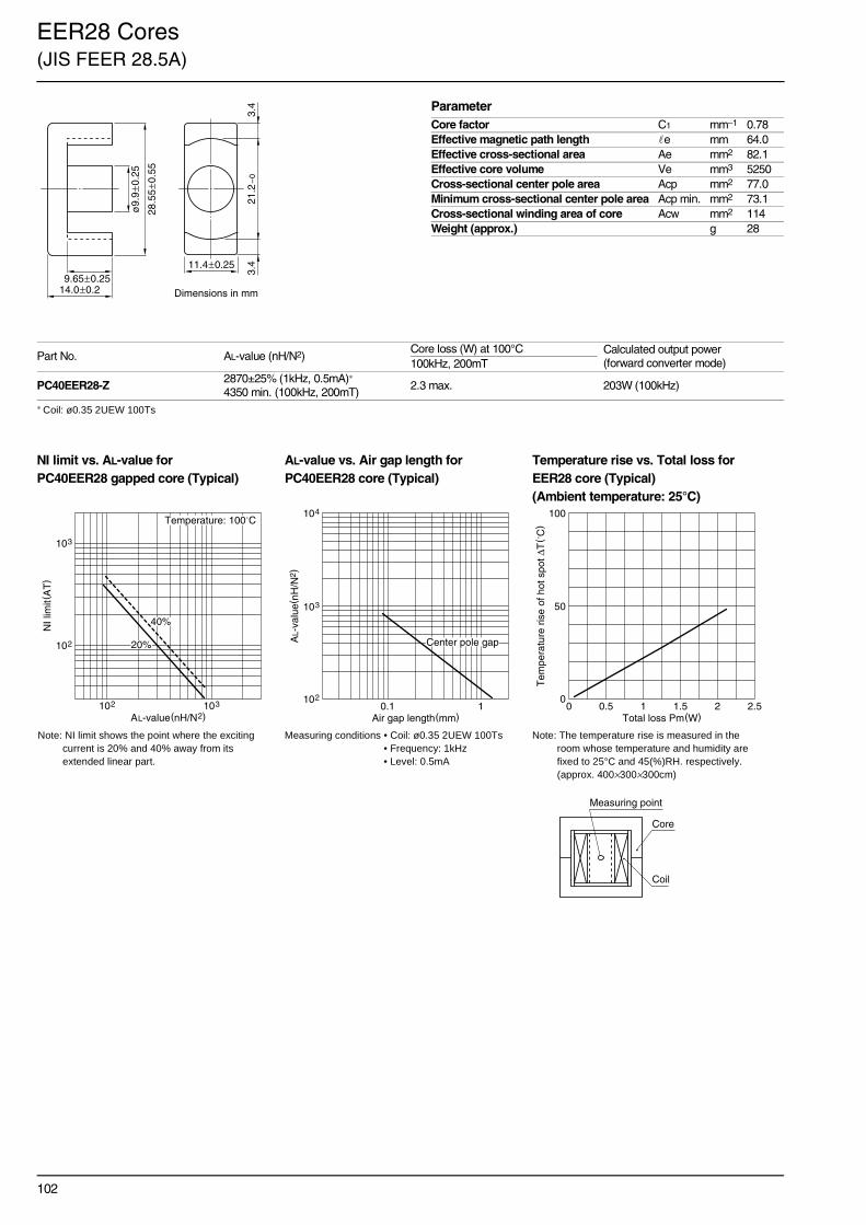
102
EER28 Cores(JIS FEER 28.5A)
∗ Coil: ø0.35 2UEW 100Ts
NI limit vs. AL-value for AL-value vs. Air gap length for Temperature rise vs. Total loss forPC40EER28 gapped core (Typical) PC40EER28 core (Typical) EER28 core (Typical)
(Ambient temperature: 25°C)
Part No. AL-value (nH/N2)Core loss (W) at 100°C Calculated output power
(forward converter mode)100kHz, 200mT
PC40EER28-Z2870±25% (1kHz, 0.5mA)∗
4350 min. (100kHz, 200mT)2.3 max. 203W (100kHz)
ParameterCore factor C1 mm–1 0.78Effective magnetic path length e mm 64.0Effective cross-sectional area Ae mm2 82.1Effective core volume Ve mm3 5250Cross-sectional center pole area Acp mm2 77.0Minimum cross-sectional center pole area Acp min. mm2 73.1Cross-sectional winding area of core Acw mm2 114Weight (approx.) g 28
14.0±0.29.65±0.25
28.5
5±0
.55
ø9.
9±0
.25
21.2
–0
3.4
3.411.4±0.25
Dimensions in mm
Note: NI limit shows the point where the exciting current is 20% and 40% away from its extended linear part.
Measuring conditions • Coil: ø0.35 2UEW 100Ts • Frequency: 1kHz• Level: 0.5mA
Note: The temperature rise is measured in the room whose temperature and humidity are fixed to 25°C and 45(%)RH. respectively. (approx. 400×300×300cm)
102
103
NI l
imit(
AT
)
AL-value(nH/N2)103102
40%
Temperature: 100˚C
20%
103
104
102
AL-
valu
e(nH
/N2 )
Air gap length(mm)10.1
Center pole gap
0
50
100
Tem
pera
ture
ris
e of
hot
spo
t ∆T
( ˚C
)
Total loss Pm(W)0 2.521.510.5
Measuring point
Coil
Core

103
EER28L Cores(JIS FEER 28.5B)
∗ Coil: ø0.35 2UEW 100Ts
NI limit vs. AL-value for AL-value vs. Air gap length for Temperature rise vs. Total loss forPC40EER28L gapped core (Typical) PC40EER28L core (Typical) EER28L core (Typical)
(Ambient temperature: 25°C)
Part No. AL-value (nH/N2)Core loss (W) at 100°C Calculated output power
(forward converter mode)100kHz, 200mT
PC40EER28L-Z2520±25% (1kHz, 0.5mA)∗
3660 min. (100kHz, 200mT)2.7 max. 228W (100kHz)
ParameterCore factor C1 mm–1 0.928Effective magnetic path length e mm 75.5Effective cross-sectional area Ae mm2 81.4Effective core volume Ve mm3 6150Cross-sectional center pole area Acp mm2 77.0Minimum cross-sectional center pole area Acp min. mm2 73.1Cross-sectional winding area of core Acw mm2 148Weight (approx.) g 33
16.9±0.25
12.53±0.28
28.5
5±0
.55
ø9.
9±0
.25
21.2
–0
3.4
3.411.4±0.25
Dimensions in mm
Note: NI limit shows the point where the exciting current is 20% and 40% away from its extended linear part.
Measuring conditions • Coil: ø0.35 2UEW 100Ts • Frequency: 1kHz• Level: 0.5mA
Note: The temperature rise is measured in the room whose temperature and humidity are fixed to 25°C and 45(%)RH. respectively. (approx. 400×300×300cm)
102
103
NI l
imit(
AT
)
AL-value(nH/N2)103102
40%
Temperature: 100˚C
20%
103
104
102
AL-
valu
e(nH
/N2 )
Air gap length(mm)10.1
Center pole gap
0
50
100
Tem
pera
ture
ris
e of
hot
spo
t ∆T
( ˚C
)
Total loss Pm(W)0 2.521.510.5
Measuring point
Coil
Core

104
EER35 Cores(JIS FEER 35A)
∗ Coil: ø0.35 2UEW 100Ts
NI limit vs. AL-value for AL-value vs. Air gap length for Temperature rise vs. Total loss forPC40EER35 gapped core (Typical) PC40EER35 core (Typical) EER35 core (Typical)
(Ambient temperature: 25°C)
Part No. AL-value (nH/N2)Core loss (W) at 100°C Calculated output power
(forward converter mode)100kHz, 200mT
PC40EER35-Z2770±25% (1kHz, 0.5mA)∗
4000 min. (100kHz, 200mT)4.2 max. 325W (100kHz)
ParameterCore factor C1 mm–1 0.849Effective magnetic path length e mm 90.8Effective cross-sectional area Ae mm2 107Effective core volume Ve mm3 9720Cross-sectional center pole area Acp mm2 100Minimum cross-sectional center pole area Acp min. mm2 97.6Cross-sectional winding area of core Acw mm2 218Weight (approx.) g 52
20.7±0.2
14.7±0.3
25.6
–0
4.43
4.43
11.3±0.2
35.0
±0.5
ø11
.3±0
.15
Dimensions in mm
Note: NI limit shows the point where the exciting current is 20% and 40% away from its extended linear part.
Measuring conditions • Coil: ø0.35 2UEW 100Ts • Frequency: 1kHz• Level: 0.5mA
Note: The temperature rise is measured in the room whose temperature and humidity are fixed to 25°C and 45(%)RH. respectively. (approx. 400×300×300cm)
102
103
NI l
imit(
AT
)
AL-value(nH/N2)103102
40%
Temperature: 100˚C
20%
103
104
102
AL-
valu
e(nH
/N2 )
Air gap length(mm)10.1
Center pole gap
0
50
100
Tem
pera
ture
ris
e of
hot
spo
t ∆T
( ˚C
)
Total loss Pm(W)0 54321
Measuring point
Coil
Core

105
EER40 Cores
∗ Coil: ø0.35 2UEW 100Ts
NI limit vs. AL-value for AL-value vs. Air gap length for Temperature rise vs. Total loss forPC40EER40 gapped core (Typical) PC40EER40 core (Typical) EER40 core (Typical)
(Ambient temperature: 25°C)
Part No. AL-value (nH/N2)Core loss (W) at 100°C Calculated output power
(forward converter mode)100kHz, 200mT
PC40EER40-Z3620±25% (1kHz, 0.5mA)∗
5160 min. (100kHz, 200mT)6.3 max. 421W (100kHz)
ParameterCore factor C1 mm–1 0.658Effective magnetic path length e mm 98.0Effective cross-sectional area Ae mm2 149Effective core volume Ve mm3 14600Cross-sectional center pole area Acp mm2 139Minimum cross-sectional center pole area Acp min. mm2 134Cross-sectional winding area of core Acw mm2 249Weight (approx.) g 78
22.4±0.2
15.4±0.3
29.0
–0
5.28
5.28
13.3±0.25
40.0
±0.5
ø13
.3±0
.25
Dimensions in mm
Note: NI limit shows the point where the exciting current is 20% and 40% away from its extended linear part.
Measuring conditions • Coil: ø0.35 2UEW 100Ts • Frequency: 1kHz• Level: 0.5mA
Note: The temperature rise is measured in the room whose temperature and humidity are fixed to 25°C and 45(%)RH. respectively. (approx. 400×300×300cm)
102
103
NI l
imit(
AT
)
AL-value(nH/N2)103102
40%
Temperature: 100˚C
20% 103
104
102
AL-
valu
e(nH
/N2 )
Air gap length(mm)10.1
Center pole gap
0
50
100
Tem
pera
ture
ris
e of
hot
spo
t ∆T
( ˚C
)
Total loss Pm(W)0 54321
Measuring point
Coil
Core

106
EER42 Cores(JIS FEER 42)
∗ Coil: ø0.35 2UEW 100Ts
NI limit vs. AL-value for AL-value vs. Air gap length for Temperature rise vs. Total loss forPC40EER42 gapped core (Typical) PC40EER42 core (Typical) EER42 core (Typical)
(Ambient temperature: 25°C)
Part No. AL-value (nH/N2)Core loss (W) at 100°C Calculated output power
(forward converter mode)100kHz, 200mT
PC40EER42-Z4690±25% (1kHz, 0.5mA)∗
6670 min. (100kHz, 200mT)8.6 max. 433W (100kHz)
ParameterCore factor C1 mm–1 0.509Effective magnetic path length e mm 98.8Effective cross-sectional area Ae mm2 194Effective core volume Ve mm3 19200Cross-sectional center pole area Acp mm2 187Minimum cross-sectional center pole area Acp min. mm2 183Cross-sectional winding area of core Acw mm2 223Weight (approx.) g 102
22.4±0.2
15.4±0.329
.4–
06.
06.
0
15.5±0.25
42.0
±0.6
ø15
.5±0
.25
Dimensions in mm
Note: NI limit shows the point where the exciting current is 20% and 40% away from its extended linear part.
Measuring conditions • Coil: ø0.35 2UEW 100Ts • Frequency: 1kHz• Level: 0.5mA
Note: The temperature rise is measured in the room whose temperature and humidity are fixed to 25°C and 45(%)RH. respectively. (approx. 400×300×300cm)
102
103
NI l
imit(
AT
)
AL-value(nH/N2)103102
40%
Temperature: 100˚C
20%
103
104
102
AL-
valu
e(nH
/N2 )
Air gap length(mm)10.1
Center pole gap
0
50
100
Tem
pera
ture
ris
e of
hot
spo
t ∆T
( ˚C
)
Total loss Pm(W)0 54321
Measuring point
Coil
Core

107
EER42/42/20 Cores
∗ Coil: ø0.35 2UEW 100Ts
NI limit vs. AL-value for AL-value vs. Air gap length for Temperature rise vs. Total loss forPC40EER42/42/20 gapped core (Typical) PC40EER42/42/20 core (Typical) EER42/42/20core (Typical)
(Ambient temperature: 25°C)
Part No. AL-value (nH/N2)Core loss (W) at 100°C Calculated output power
(forward converter mode)100kHz, 200mT
PC40EER42/42/20-Z5340±25% (1kHz, 0.5mA)∗
8260 min. (100kHz, 200mT)10.7 max. 509W (100kHz)
ParameterCore factor C1 mm–1 0.411Effective magnetic path length e mm 98.6Effective cross-sectional area Ae mm2 240Effective core volume Ve mm3 23700Cross-sectional center pole area Acp mm2 235Minimum cross-sectional center pole area Acp min. mm2 228Cross-sectional winding area of core Acw mm2 229Weight (approx.) g 116
21.2±0.215.25±0.25
42.1
5±0
.65
ø17
.3±0
.25
31.8
–0
4.93
4.9319.6±0.4
Dimensions in mm
Note: NI limit shows the point where the exciting current is 20% and 40% away from its extended linear part.
Measuring conditions • Coil: ø0.35 2UEW 100Ts • Frequency: 1kHz• Level: 0.5mA
Note: The temperature rise is measured in the room whose temperature and humidity are fixed to 25°C and 45(%)RH. respectively. (approx. 400×300×300cm)
102
103
NI l
imit(
AT
)
AL-value(nH/N2)103102
40%
Temperature: 100˚C
20%
103
104
102
AL-
valu
e(nH
/N2 )
Air gap length(mm)10.1
Center pole gap
0
50
100
Tem
pera
ture
ris
e of
hot
spo
t ∆T
( ˚C
)
Total loss Pm(W)0 54321
Measuring point
Coil
Core

108
ETD19 Cores
∗ Coil: ø0.35 2UEW 100Ts
NI limit vs. AL-value for AL-value vs. Air gap length for Temperature rise vs. Total loss forPC40ETD19 gapped core (Typical) PC40ETD19 core (Typical) ETD19 core (Typical)
(Ambient temperature: 25°C)
Part No. AL-value (nH/N2)Core loss (W) at 100°C Calculated output power
(forward converter mode)100kHz, 200mT
PC40ETD19-Z1720±25% (1kHz, 0.5mA)∗
2380 min. (100kHz, 200mT)1.1 max. 79W (100kHz)
ParameterCore factor C1 mm–1 1.32Effective magnetic path length e mm 54.6Effective cross-sectional area Ae mm2 41.3Effective core volume Ve mm3 2260Cross-sectional center pole area Acp mm2 43Minimum cross-sectional center pole area Acp min. mm2 40.7Cross-sectional winding area of core Acw mm2 70.5Weight (approx.) g 13.3
27.3±0.3
9.4±0.2 4.2513.65±0.15
14.9
±0.5
19.6
±0.5
ø7.
4±0
.2
7.4±0.2
Dimensions in mm
Note: NI limit shows the point where the exciting current is 20% and 40% away from its extended linear part.
Measuring conditions • Coil: ø0.35 2UEW 100Ts • Frequency: 1kHz• Level: 0.5mA
Note: The temperature rise is measured in the room whose temperature and humidity are fixed to 25°C and 45(%)RH. respectively. (approx. 400×300×300cm)
Measuring point
Coil
Core
10
102
NI l
imit(
AT
)
AL-value(nH/N2)103102
40%
Temperature: 100˚C
20%
103
102
AL-
valu
e(nH
/N2 )
Air gap length(mm)10.1
Center pole gap
0
50
100
Tem
pera
ture
ris
e of
hot
spo
t ∆T
( ˚C
)
Total loss Pm(W)0 2.521.510.5

109
ETD24 Cores
∗ Coil: ø0.35 2UEW 100Ts
NI limit vs. AL-value for AL-value vs. Air gap length for Temperature rise vs. Total loss forPC40ETD24 gapped core (Typical) PC40ETD24 core (Typical) ETD24 core (Typical)
(Ambient temperature: 25°C)
Part No. AL-value (nH/N2)Core loss (W) at 100°C Calculated output power
(forward converter mode)100kHz, 200mT
PC40ETD24-Z2125±25% (1kHz, 0.5mA)∗
2860 min. (100kHz, 200mT)1.6 max. 115W (100kHz)
ParameterCore factor C1 mm–1 1.10Effective magnetic path length e mm 61.9Effective cross-sectional area Ae mm2 56.3Effective core volume Ve mm3 3480Cross-sectional center pole area Acp mm2 56.7Minimum cross-sectional center pole area Acp min. mm2 54.1Cross-sectional winding area of core Acw mm2 102Weight (approx.) g 19.5
28.9±0.3
10.1±0.2 4.3514.45±0.15
18.6
±0.6
24.4
±0.6
ø8.
5±0
.2
8.5±0.4
Dimensions in mm
Note: NI limit shows the point where the exciting current is 20% and 40% away from its extended linear part.
Measuring conditions • Coil: ø0.35 2UEW 100Ts • Frequency: 1kHz• Level: 0.5mA
Note: The temperature rise is measured in the room whose temperature and humidity are fixed to 25°C and 45(%)RH. respectively. (approx. 400×300×300cm)
Measuring point
Coil
Core
10
102
NI l
imit(
AT
)
AL-value(nH/N2)103102
40%
Temperature: 100˚C
20%
103
102
AL-
valu
e(nH
/N2 )
Air gap length(mm)10.1
Center pole gap
0
50
100
Tem
pera
ture
ris
e of
hot
spo
t ∆T
( ˚C
)
Total loss Pm(W)0 2.521.510.5

110
ETD29 Cores
∗ Coil: ø0.35 2UEW 100Ts
NI limit vs. AL-value for AL-value vs. Air gap length for Temperature rise vs. Total loss forPC40ETD29 gapped core (Typical) PC40ETD29 core (Typical) ETD29 core (Typical)
(Ambient temperature: 25°C)
Part No. AL-value (nH/N2)Core loss (W) at 100°C Calculated output power
(forward converter mode)100kHz, 200mT
PC40ETD29-Z2500±25% (1kHz, 0.5mA)∗
3540 min. (100kHz, 200mT)2.4 max. 170W (100kHz)
ParameterCore factor C1 mm–1 0.959Effective magnetic path length e mm 70.6Effective cross-sectional area Ae mm2 73.6Effective core volume Ve mm3 5170Cross-sectional center pole area Acp mm2 70.9Minimum cross-sectional center pole area Acp min. mm2 66.5Cross-sectional winding area of core Acw mm2 145.2Weight (approx.) g 28
31.6±0.3
11.0±0.3 4.815.8±0.15
22.7
±0.7
29.8
±0.8
ø9.
5±0
.3
9.5±0.3
Dimensions in mm
Note: NI limit shows the point where the exciting current is 20% and 40% away from its extended linear part.
Measuring conditions • Coil: ø0.35 2UEW 100Ts • Frequency: 1kHz• Level: 0.5mA
Note: The temperature rise is measured in the room whose temperature and humidity are fixed to 25°C and 45(%)RH. respectively. (approx. 400×300×300cm)
Measuring point
Coil
Core
10
102
NI l
imit(
AT
)
AL-value(nH/N2)103102
40%
Temperature: 100˚C
20%
103
102
AL-
valu
e(nH
/N2 )
Air gap length(mm)10.1
Center pole gap
0
50
100
Tem
pera
ture
ris
e of
hot
spo
t ∆T
( ˚C
)
Total loss Pm(W)0 2.521.510.5

111
ETD34 Cores
∗ Coil: ø0.35 2UEW 100Ts
NI limit vs. AL-value for AL-value vs. Air gap length for Temperature rise vs. Total loss forPC40ETD34 gapped core (Typical) PC40ETD34 core (Typical) ETD34 core (Typical)
(Ambient temperature: 25°C)
Part No. AL-value (nH/N2)Core loss (W) at 100°C Calculated output power
(forward converter mode)100kHz, 200mT
PC40ETD34-Z2780±25% (1kHz, 0.5mA)∗
4190 min. (100kHz, 200mT)3.31 max. 271W (100kHz)
ParameterCore factor C1 mm–1 0.810Effective magnetic path length e mm 78.6Effective cross-sectional area Ae mm2 97.1Effective core volume Ve mm3 7630Cross-sectional center pole area Acp mm2 91.6Minimum cross-sectional center pole area Acp min. mm2 86.6Cross-sectional winding area of core Acw mm2 188Weight (approx.) g 40
34.6±0.4
12.1±0.3 5.217.3±0.2
26.3
±0.7
34.2
±0.8
ø10
.8±0
.3
10.88±0.38
Dimensions in mm
Note: NI limit shows the point where the exciting current is 20% and 40% away from its extended linear part.
Measuring conditions • Coil: ø0.35 2UEW 100Ts • Frequency: 1kHz• Level: 0.5mA
Note: The temperature rise is measured in the room whose temperature and humidity are fixed to 25°C and 45(%)RH. respectively. (approx. 400×300×300cm)
102
103
NI l
imit(
AT
)
AL-value(nH/N2)103102
40%
20%
Temperature: 100˚C
103
102
AL-
valu
e(nH
/N2 )
Air gap length(mm)10.1
Center pole gap
0
50
100
Tem
pera
ture
ris
e of
hot
spo
t ∆T
( ˚C
)
Total loss Pm(W)0 54321
Measuring point
Coil
Core

112
ETD39 Cores
∗ Coil: ø0.35 2UEW 100Ts
NI limit vs. AL-value for AL-value vs. Air gap length for Temperature rise vs. Total loss forPC40ETD39 gapped core (Typical) PC40ETD39 core (Typical) ETD39 core (Typical)
(Ambient temperature: 25°C)
Part No. AL-value (nH/N2)Core loss (W) at 100°C Calculated output power
(forward converter mode)100kHz, 200mT
PC40ETD39-Z3150±25% (1kHz, 0.5mA)∗
4600 min. (100kHz, 200mT)5.3 max. 382W (100kHz)
ParameterCore factor C1 mm–1 0.737Effective magnetic path length e mm 92.1Effective cross-sectional area Ae mm2 125Effective core volume Ve mm3 11500Cross-sectional center pole area Acp mm2 123Minimum cross-sectional center pole area Acp min. mm2 117Cross-sectional winding area of core Acw mm2 257Weight (approx.) g 60
39.6±0.4
14.6±0.4 5.219.8±0.2
30.1
±0.8
39.1
±0.9
ø12
.5±0
.312.58±0.38
Dimensions in mm
Note: NI limit shows the point where the exciting current is 20% and 40% away from its extended linear part.
Measuring conditions • Coil: ø0.35 2UEW 100Ts • Frequency: 1kHz• Level: 0.5mA
Note: The temperature rise is measured in the room whose temperature and humidity are fixed to 25°C and 45(%)RH. respectively. (approx. 400×300×300cm)
102
103
NI l
imit(
AT
)
AL-value(nH/N2)103102
40%
20%
Temperature: 100˚C
103
102
AL-
valu
e(nH
/N2 )
Air gap length(mm)10.1
Center pole gap
0
50
100
Tem
pera
ture
ris
e of
hot
spo
t ∆T
( ˚C
)
Total loss Pm(W)0 54321
Measuring point
Coil
Core

113
ETD44 Cores
∗ Coil: ø0.35 2UEW 100Ts
NI limit vs. AL-value for AL-value vs. Air gap length for Temperature rise vs. Total loss forPC40ETD44 gapped core (Typical) PC40ETD44 core (Typical) ETD44 core (Typical)
(Ambient temperature: 25°C)
Part No. AL-value (nH/N2)Core loss (W) at 100°C Calculated output power
(forward converter mode)100kHz, 200mT
PC40ETD44-Z4000±25% (1kHz, 0.5mA)∗
5760 min. (100kHz, 200mT)8.3 max. 523W (100kHz)
ParameterCore factor C1 mm–1 0.589Effective magnetic path length e mm 103Effective cross-sectional area Ae mm2 175Effective core volume Ve mm3 18000Cross-sectional center pole area Acp mm2 172Minimum cross-sectional center pole area Acp min. mm2 163Cross-sectional winding area of core Acw mm2 305Weight (approx.) g 94
44.6±0.4
16.5±0.4 5.822.3±0.2
33.3
±0.8
44.0
±1.0
ø14
.8±0
.4
14.9±0.5
Dimensions in mm
Note: NI limit shows the point where the exciting current is 20% and 40% away from its extended linear part.
Measuring conditions • Coil: ø0.35 2UEW 100Ts • Frequency: 1kHz• Level: 0.5mA
Note: The temperature rise is measured in the room whose temperature and humidity are fixed to 25°C and 45(%)RH. respectively. (approx. 400×300×300cm)
102
103
NI l
imit(
AT
)
AL-value(nH/N2)103102
40%
20%
Temperature: 100˚C
103
102
AL-
valu
e(nH
/N2 )
Air gap length(mm)10.1
Center pole gap
0
50
100
Tem
pera
ture
ris
e of
hot
spo
t ∆T
( ˚C
)
Total loss Pm(W)0 54321
Measuring point
Coil
Core

114
ETD49 Cores
∗ Coil: ø0.35 2UEW 100Ts
NI limit vs. AL-value for AL-value vs. Air gap length for Temperature rise vs. Total loss forPC40ETD49 gapped core (Typical) PC40ETD49 core (Typical) ETD49 core (Typical)
(Ambient temperature: 25°C)
Part No. AL-value (nH/N2)Core loss (W) at 100°C Calculated output power
(forward converter mode)100kHz, 200mT
PC40ETD49-Z4440±25% (1kHz, 0.5mA)∗
6340 min. (100kHz, 200mT)11.2 max. 682W (100kHz)
ParameterCore factor C1 mm–1 0.535Effective magnetic path length e mm 114Effective cross-sectional area Ae mm2 213Effective core volume Ve mm3 24300Cross-sectional center pole area Acp mm2 209Minimum cross-sectional center pole area Acp min. mm2 199Cross-sectional winding area of core Acw mm2 375Weight (approx.) g 124
49.4±0.4
18.1±0.4 6.624.7±0.2
37.0
±0.9
48.7
±1.1
ø16
.3±0
.416.4±0.5
Dimensions in mm
Note: NI limit shows the point where the exciting current is 20% and 40% away from its extended linear part.
Measuring conditions • Coil: ø0.35 2UEW 100Ts • Frequency: 1kHz• Level: 0.5mA
Note: The temperature rise is measured in the room whose temperature and humidity are fixed to 25°C and 45(%)RH. respectively. (approx. 400×300×300cm)
102
103
NI l
imit(
AT
)
AL-value(nH/N2)103102
40%
20%
Temperature: 100˚C
103
102
AL-
valu
e(nH
/N2 )
Air gap length(mm)10.1
Center pole gap
0
50
100
Tem
pera
ture
ris
e of
hot
spo
t ∆T
( ˚C
)
Total loss Pm(W)0 54321
Measuring point
Coil
Core

115
PQ20/16 Cores
∗ Coil: ø0.35 2UEW 100Ts
NI limit vs. AL-value for AL-value vs. Air gap length for Temperature rise vs. Total loss forPC44PQ20/16 gapped core (Typical) PC44PQ20/16 core (Typical) PQ20/16 core (Typical)
(Ambient temperature: 25°C)
Part No. AL-value (nH/N2)Core loss (W) at 100°C Calculated output power
(forward converter mode)100kHz, 200mT
PC44PQ20/16Z-123880±25% (1kHz, 0.5mA)∗
5210 min. (100kHz, 200mT)0.84 max. 70W (100kHz)
ParameterCore factor C1 mm–1 0.603Effective magnetic path length e mm 37.4Effective cross-sectional area Ae mm2 62Effective core volume Ve mm3 2310Cross-sectional center pole area Acp mm2 60.8Minimum cross-sectional center pole area Acp min. mm2 58.1Cross-sectional winding area of core Acw mm2 47.4Weight (approx.) g 13
14.0±0.4
12.0
–0
16.2±0.2
10.3±0.3
ø8.
8±0
.2
18.0
±0.4
20.5
±0.4
Dimensions in mm
Note: NI limit shows the point where the exciting current is 20% and 40% away from its extended linear part.
Measuring conditions • Coil: ø0.35 2UEW 100Ts • Frequency: 1kHz• Level: 0.5mA
Note: The temperature rise is measured in the room whose temperature and humidity are fixed to 25°C and 45(%)RH. respectively. (approx. 400×300×300cm)
102
101
103
NI l
imit(
AT
)
AL-value(nH/N2)103102
40%
20%
Temperature: 100˚C
NI limit=28821×AL–1.022(20%)NI limit=38270×AL–1.038(40%)AL=22862×NI limit–0.978(20%)AL=26409×NI limit–0.964(40%)
102
103
101
AL-
valu
e(nH
/N2 )
Air gap length(mm)1010.1
Center pole gap
Spacer gap
0
50
100
Tem
pera
ture
ris
e of
hot
spo
t ∆T
( ˚C
)
Total loss Pm(W)0 54321
Measuring point
Coil
Core

116
PQ20/20 Cores
∗ Coil: ø0.35 2UEW 100Ts
NI limit vs. AL-value for AL-value vs. Air gap length for Temperature rise vs. Total loss forPC44PQ20/20 gapped core (Typical) PC44PQ20/20 core (Typical) PQ20/20 core (Typical)
(Ambient temperature: 25°C)
NI limit vs. AL-value for AL-value vs. Air gap length forPC50PQ20/20 gapped core (Typical) PC50PQ20/20 core (Typical)
Part No. AL-value (nH/N2)Core loss (W) at 100°C Calculated output power
(forward converter mode)100kHz, 200mT 500kHz, 50mT
PC44PQ20/20Z-123150±25% (1kHz, 0.5mA)∗
4290 min. (100kHz, 200mT)1.02 max. 92W (100kHz)
PC50PQ20/20Z-12 2000±25% (1kHz, 0.5mA)∗ 0.33 max. 187W (500kHz)
ParameterCore factor C1 mm–1 0.732Effective magnetic path length e mm 45.4Effective cross-sectional area Ae mm2 62Effective core volume Ve mm3 2790Cross-sectional center pole area Acp mm2 60.8Minimum cross-sectional center pole area Acp min. mm2 58.1Cross-sectional winding area of core Acw mm2 65.8Weight (approx.) g 15
14.0±0.4
12.0
–0
20.2±0.2
14.3±0.3
ø8.
8±0
.2
18.0
±0.4
20.5
±0.4
Dimensions in mm
Note: The temperature rise is measured in the room whose temperature and humidity are fixed to 25°C and 45(%)RH. respectively. (approx. 400×300×300cm)
102
101
103
NI l
imit(
AT
)
AL-value(nH/N2)103102
40%
20%
Temperature: 100˚C
NI limit=27144×AL–1.017(20%)NI limit=33834×AL–1.018(40%)AL=22840×NI limit–0.983(20%)AL=28428×NI limit–0.983(40%)
102
103
101
AL-
valu
e(nH
/N2 )
Air gap length(mm)1010.1
Center pole gap
Spacer gap
0
50
100T
empe
ratu
re r
ise
of h
ot s
pot ∆
T( ˚
C)
Total loss Pm(W)0 54321
Measuring point
Coil
Core
Note: NI limit shows the point where the exciting current is 20% and 40% away from its extended linear part.
Measuring conditions • Coil: ø0.35 2UEW 100Ts • Frequency: 1kHz• Level: 0.5mA
102
101
103
NI l
imit(
AT
)
AL-value(nH/N2)103102
40%
20%
Temperature: 100˚C
102
103
101
AL-
valu
e(nH
/N2 )
Air gap length(mm)1010.1
Center pole gap

117
PQ26/20 Cores
∗ Coil: ø0.35 2UEW 100Ts
NI limit vs. AL-value for AL-value vs. Air gap length for Temperature rise vs. Total loss forPC44PQ26/20 gapped core (Typical) PC44PQ26/20 core (Typical) PQ26/20 core (Typical)
(Ambient temperature: 25°C)
Part No. AL-value (nH/N2)Core loss (W) at 100°C Calculated output power
(forward converter mode)100kHz, 200mT
PC44PQ26/20Z-126170±25% (1kHz, 0.5mA)∗
8060 min. (100kHz, 200mT)1.94 max. 170W (100kHz)
ParameterCore factor C1 mm–1 0.389Effective magnetic path length e mm 46.3Effective cross-sectional area Ae mm2 119Effective core volume Ve mm3 5490Cross-sectional center pole area Acp mm2 113Minimum cross-sectional center pole area Acp min. mm2 109Cross-sectional winding area of core Acw mm2 60.4Weight (approx.) g 31
19.0±0.45
20.15±0.25
11.5±0.3
ø12
.0±0
.2
22.5
±0.4
5
26.5
±0.4
5
15.5
–0
Dimensions in mm
Note: NI limit shows the point where the exciting current is 20% and 40% away from its extended linear part.
Measuring conditions • Coil: ø0.35 2UEW 100Ts • Frequency: 1kHz• Level: 0.5mA
Note: The temperature rise is measured in the room whose temperature and humidity are fixed to 25°C and 45(%)RH. respectively. (approx. 400×300×300cm)
102
101
103
NI l
imit(
AT
)
AL-value(nH/N2)103102
40%
20%
Temperature: 100˚C
NI limit=63599×AL–1.053(20%)NI limit=80460×AL–1.050(40%)AL=36698×NI limit–0.950(20%)AL=47452×NI limit–0.953(40%)
102
103
101
AL-
valu
e(nH
/N2 )
Air gap length(mm)1010.1
Center pole gap
Spacer gap
0
50
100
Tem
pera
ture
ris
e of
hot
spo
t ∆T
( ˚C
)
Total loss Pm(W)0 54321
Measuring point
Coil
Core

118
PQ26/25 Cores
∗ Coil: ø0.35 2UEW 100Ts
NI limit vs. AL-value for AL-value vs. Air gap length for Temperature rise vs. Total loss forPC44PQ26/25 gapped core (Typical) PC44PQ26/25 core (Typical) PQ26/25 core (Typical)
(Ambient temperature: 25°C)
NI limit vs. AL-value for AL-value vs. Air gap length forPC50PQ26/25 gapped core (Typical) PC50PQ26/25 core (Typical)
Part No. AL-value (nH/N2)Core loss (W) at 100°C Calculated output power
(forward converter mode)100kHz, 200mT 500kHz, 50mT
PC44PQ26/25Z-125250±25% (1kHz, 0.5mA)∗
6680 min. (100kHz, 200mT)2.32 max. 195W (100kHz)
PC50PQ26/25Z-12 3200±25% (1kHz, 0.5mA)∗ 0.76 max. 366W (500kHz)
ParameterCore factor C1 mm–1 0.470Effective magnetic path length e mm 55.5Effective cross-sectional area Ae mm2 118Effective core volume Ve mm3 6530Cross-sectional center pole area Acp mm2 113Minimum cross-sectional center pole area Acp min. mm2 109Cross-sectional winding area of core Acw mm2 84.5Weight (approx.) g 36
19.0±0.45
24.75±0.25
16.1±0.3
ø12
.0±0
.2
22.5
±0.4
5
26.5
±0.4
5
15.5
–0
Dimensions in mm
Note: The temperature rise is measured in the room whose temperature and humidity are fixed to 25°C and 45(%)RH. respectively. (approx. 400×300×300cm)
102
101
103
NI l
imit(
AT
)
AL-value(nH/N2)103102
40%
20%
Temperature: 100˚C
NI limit=76619×AL–1.087(20%)NI limit=93743×AL–1.086(40%)AL=31132×NI limit–0.920(20%)AL=38138×NI limit–0.921(40%)
102
103
101
AL-
valu
e(nH
/N2 )
Air gap length(mm)1010.1
Center pole gap
Spacer gap
0
50
100T
empe
ratu
re r
ise
of h
ot s
pot ∆
T( ˚
C)
Total loss Pm(W)0 54321
Measuring point
Coil
Core
Note: NI limit shows the point where the exciting current is 20% and 40% away from its extended linear part.
Measuring conditions • Coil: ø0.35 2UEW 100Ts • Frequency: 1kHz• Level: 0.5mA
102
101
103
NI l
imit(
AT
)
AL-value(nH/N2)103102
40%
20%
Temperature: 100˚C
102
103
101
AL-
valu
e(nH
/N2 )
Air gap length(mm)10.1
Center pole gap
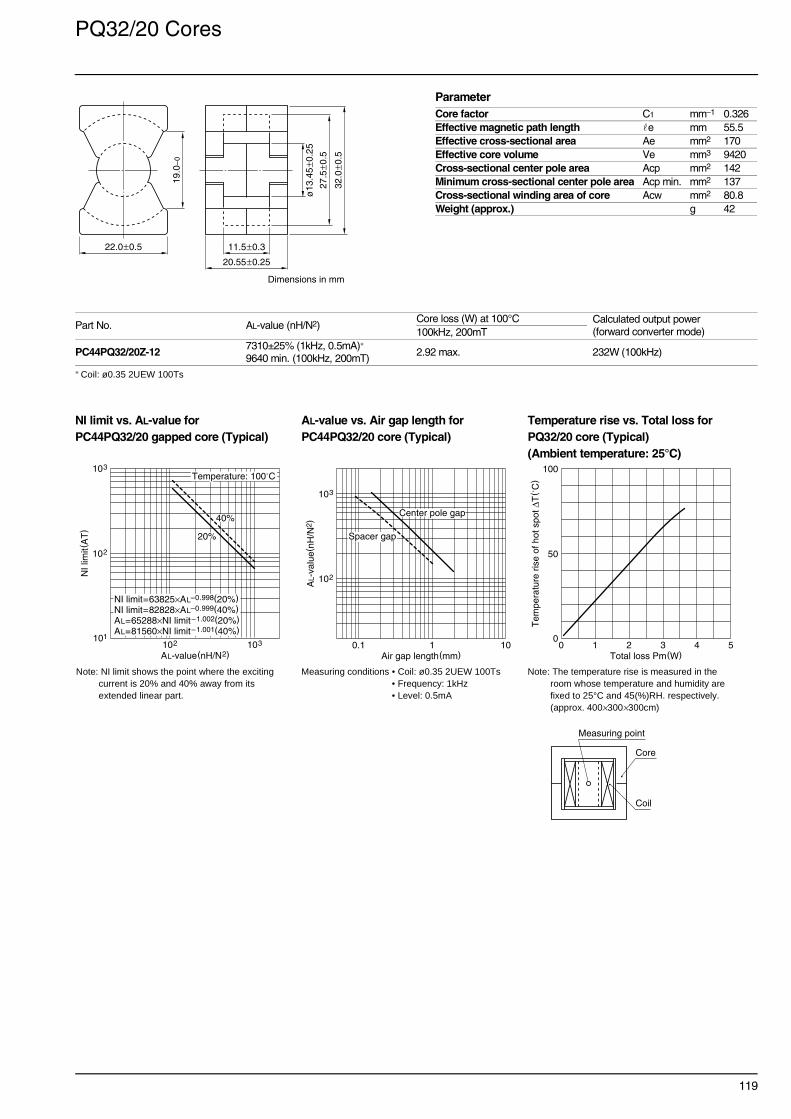
119
PQ32/20 Cores
∗ Coil: ø0.35 2UEW 100Ts
NI limit vs. AL-value for AL-value vs. Air gap length for Temperature rise vs. Total loss forPC44PQ32/20 gapped core (Typical) PC44PQ32/20 core (Typical) PQ32/20 core (Typical)
(Ambient temperature: 25°C)
Part No. AL-value (nH/N2)Core loss (W) at 100°C Calculated output power
(forward converter mode)100kHz, 200mT
PC44PQ32/20Z-127310±25% (1kHz, 0.5mA)∗
9640 min. (100kHz, 200mT)2.92 max. 232W (100kHz)
ParameterCore factor C1 mm–1 0.326Effective magnetic path length e mm 55.5Effective cross-sectional area Ae mm2 170Effective core volume Ve mm3 9420Cross-sectional center pole area Acp mm2 142Minimum cross-sectional center pole area Acp min. mm2 137Cross-sectional winding area of core Acw mm2 80.8Weight (approx.) g 42
22.0±0.5
20.55±0.25
11.5±0.3
ø13
.45
±0.2
5
27.5
±0.5
32.0
±0.5
19.0
–0
Dimensions in mm
Note: NI limit shows the point where the exciting current is 20% and 40% away from its extended linear part.
Measuring conditions • Coil: ø0.35 2UEW 100Ts • Frequency: 1kHz• Level: 0.5mA
Note: The temperature rise is measured in the room whose temperature and humidity are fixed to 25°C and 45(%)RH. respectively. (approx. 400×300×300cm)
102
101
103
NI l
imit(
AT
)
AL-value(nH/N2)103102
40%
20%
Temperature: 100˚C
NI limit=63825×AL–0.998(20%)NI limit=82828×AL–0.999(40%)AL=65288×NI limit–1.002(20%)AL=81560×NI limit–1.001(40%)
102
103
AL-
valu
e(nH
/N2 )
Air gap length(mm)1010.1
Center pole gap
Spacer gap
0
50
100
Tem
pera
ture
ris
e of
hot
spo
t ∆T
( ˚C
)
Total loss Pm(W)0 54321
Measuring point
Coil
Core

120
PQ32/30 Cores
∗ Coil: ø0.4 2UEW 100Ts
NI limit vs. AL-value for AL-value vs. Air gap length for Temperature rise vs. Total loss forPC44PQ32/30 gapped core (Typical) PC44PQ32/30 core (Typical) PQ32/30 core (Typical)
(Ambient temperature: 25°C)
Part No. AL-value (nH/N2)Core loss (W) at 100°C Calculated output power
(forward converter mode)100kHz, 200mT
PC44PQ32/30Z-125140±25% (1kHz, 0.5mA)∗
6790 min. (100kHz, 200mT)3.92 max. 331W (100kHz)
ParameterCore factor C1 mm–1 0.463Effective magnetic path length e mm 74.6Effective cross-sectional area Ae mm2 161Effective core volume Ve mm3 11970Cross-sectional center pole area Acp mm2 142Minimum cross-sectional center pole area Acp min. mm2 137Cross-sectional winding area of core Acw mm2 149.6Weight (approx.) g 55
22.0±0.5
30.35±0.25
21.3±0.3
ø13
.45
±0.2
5
27.5
±0.5
32.0
±0.5
19.0
–0
Dimensions in mm
Note: NI limit shows the point where the exciting current is 20% and 40% away from its extended linear part.
Measuring conditions • Coil: ø0.4 2UEW 100Ts • Frequency: 1kHz• Level: 0.5mA
Note: The temperature rise is measured in the room whose temperature and humidity are fixed to 25°C and 45(%)RH. respectively. (approx. 400×300×300cm)
102
101
103
NI l
imit(
AT
)
AL-value(nH/N2)103102
40%
20%
Temperature: 100˚C
NI limit=121567×AL–1.110(20%)NI limit=135490×AL–1.086(40%)AL=38232×NI limit–0.901(20%)AL=52632×NI limit–0.921(40%)
102
103
AL-
valu
e(nH
/N2 )
Air gap length(mm)1010.1
Spacer gap
Center pole gap
0
50
100
Tem
pera
ture
ris
e of
hot
spo
t ∆T
( ˚C
)
Total loss Pm(W)0 54321
Measuring point
Coil
Core

121
PQ35/35 Cores
∗ Coil: ø0.4 2UEW 100Ts
NI limit vs. AL-value for AL-value vs. Air gap length for Temperature rise vs. Total loss forPC44PQ35/35 gapped core (Typical) PC44PQ35/35 core (Typical) PQ35/35 core (Typical)
(Ambient temperature: 25°C)
Part No. AL-value (nH/N2)Core loss (W) at 100°C Calculated output power
(forward converter mode)100kHz, 200mT
PC44PQ35/35Z-124860±25% (1kHz, 0.5mA)∗
7010 min. (100kHz, 200mT)5.27 max. 452W (100kHz)
ParameterCore factor C1 mm–1 0.448Effective magnetic path length e mm 87.9Effective cross-sectional area Ae mm2 196Effective core volume Ve mm3 17200Cross-sectional center pole area Acp mm2 162Minimum cross-sectional center pole area Acp min. mm2 156Cross-sectional winding area of core Acw mm2 220.6Weight (approx.) g 73
26.0±0.5
34.75±0.25
25.0±0.3
ø14
.35
±0.2
5
32.0
±0.5
35.1
±0.6
23.5
–0
Dimensions in mm
Note: NI limit shows the point where the exciting current is 20% and 40% away from its extended linear part.
Measuring conditions • Coil: ø0.4 2UEW 100Ts • Frequency: 1kHz• Level: 0.5mA
Note: The temperature rise is measured in the room whose temperature and humidity are fixed to 25°C and 45(%)RH. respectively. (approx. 400×300×300cm)
102
101
103
NI l
imit(
AT
)
AL-value(nH/N2)103102
40%
20%
Temperature: 100˚C
NI limit=124531×AL–1.107(20%)NI limit=154965×AL–1.103(40%)AL=39836×NI limit–0.903(20%)AL=50738×NI limit–0.906(40%)
102
103
AL-
valu
e(nH
/N2 )
Air gap length(mm)1010.1
Spacer gap
Center pole gap
0
50
100
Tem
pera
ture
ris
e of
hot
spo
t ∆T
( ˚C
)
Total loss Pm(W)0 54321
Measuring point
Coil
Core

122
PQ40/40 Cores
∗ Coil: ø0.4 2UEW 100Ts
NI limit vs. AL-value for AL-value vs. Air gap length for Temperature rise vs. Total loss forPC44PQ40/40 gapped core (Typical) PC44PQ40/40 core (Typical) PQ40/40 core (Typical)
Part No. AL-value (nH/N2)Core loss (W) at 100°C Calculated output power
(forward converter mode)100kHz, 200mT
PC44PQ40/40Z-124300±25% (1kHz, 0.5mA)∗
6200 min. (100kHz, 200mT)6.56 max. 596W (100kHz)
ParameterCore factor C1 mm–1 0.507Effective magnetic path length e mm 102Effective cross-sectional area Ae mm2 201Effective core volume Ve mm3 20500Cross-sectional center pole area Acp mm2 174Minimum cross-sectional center pole area Acp min. mm2 167Cross-sectional winding area of core Acw mm2 326Weight (approx.) g 95
28.0±0.6
39.75±0.25
29.5±0.3
ø14
.9±0
.3
37.0
±0.6
40.5
±0.9
28.0
–0
Dimensions in mm
Note: NI limit shows the point where the exciting current is 20% and 40% away from its extended linear part.
Measuring conditions • Coil: ø0.4 2UEW 100Ts • Frequency: 1kHz• Level: 0.5mA
Note: The temperature rise is measured in the room whose temperature and humidity are fixed to 25°C and 45(%)RH. respectively. (approx. 400×300×300cm)
102
101
103
NI l
imit(
AT
)
AL-value(nH/N2)103102
40%
20%
Temperature: 100˚C
NI limit=134431×AL–1.106(20%)NI limit=161112×AL–1.095(40%)AL=43295×NI limit–0.904(20%)AL=57069×NI limit–0.914(40%)
102
103
AL-
valu
e(nH
/N2 )
Air gap length(mm)1010.1
Spacer gap
Center pole gap
0
50
100
Tem
pera
ture
ris
e of
hot
spo
t ∆T
( ˚C
)
Total loss Pm(W)0 105
Measuring point
Coil
Core
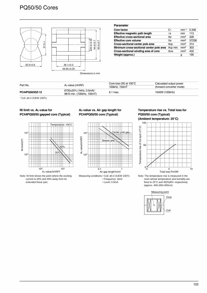
123
PQ50/50 Cores
∗ Coil: ø0.4 2UEW 100Ts
NI limit vs. AL-value for AL-value vs. Air gap length for Temperature rise vs. Total loss forPC44PQ50/50 gapped core (Typical) PC44PQ50/50 core (Typical) PQ50/50 core (Typical)
(Ambient temperature: 25°C)
Part No. AL-value (nH/N2)Core loss (W) at 100°C Calculated output power
(forward converter mode)100kHz, 150mT
PC44PQ50/50Z-126720±25% (1kHz, 0.5mA)∗
9810 min. (100kHz, 150mT)6.1 max. 1045W (100kHz)
ParameterCore factor C1 mm–1 0.346Effective magnetic path length e mm 113Effective cross-sectional area Ae mm2 328Effective core volume Ve mm3 37238Cross-sectional center pole area Acp mm2 314Minimum cross-sectional center pole area Acp min. mm2 303Cross-sectional winding area of core Acw mm2 433Weight (approx.) g 195
32.0±0.6
49.95±0.25
36.1±0.3
ø20
.0±0
.35
44.0
±0.7
50.0
±0.7
31.5
–0
Dimensions in mm
Note: NI limit shows the point where the exciting current is 20% and 40% away from its extended linear part.
Measuring conditions • Coil: ø0.4 2UEW 100Ts • Frequency: 1kHz• Level: 0.5mA
Note: The temperature rise is measured in the room whose temperature and humidity are fixed to 25°C and 45(%)RH. respectively. (approx. 400×300×300cm)
102
103
NI l
imit(
AT
)
AL-value(nH/N2)103102
40%
20%
Temperature: 100˚C
102
103
AL-
valu
e(nH
/N2 )
Air gap length(mm)10.1
Spacer gap
Center pole gap
0
50
100
Tem
pera
ture
ris
e of
hot
spo
t ∆T
( ˚C
)
Total loss Pm(W)0 105
Measuring point
Coil
Core

124
LP23/8 Cores
∗ Coil: ø0.35 2UEW 100Ts
NI limit vs. AL-value for AL-value vs. Air gap length for Temperature rise vs. Total loss forPC44LP23/8 gapped core (Typical) PC44LP23/8 core (Typical) LP23/8 core (Typical)
(Ambient temperature: 25°C)
Part No. AL-value (nH/N2)Core loss (W) at 100°C Calculated output power
(forward converter mode)100kHz, 200mT
PC44LP23/8Z-121600±25% (1kHz, 0.5mA)∗
2230 min. (100kHz, 200mT)0.42 max. 50W (100kHz)
ParameterCore factor C1 mm–1 1.41Effective magnetic path length e mm 44.1Effective cross-sectional area Ae mm2 31.3Effective core volume Ve mm3 1380Cross-sectional center pole area Acp mm2 25.5Minimum cross-sectional center pole area Acp min. mm2 24.6Cross-sectional winding area of core Acw mm2 59.2Weight (approx.) g 9.6
ø5.7±0.1
9.0±0.5
12.5±0.3
17.4±0.2
23.4±0.2
16.5±0.3
8.7±
0.2
Dimensions in mm
Note: NI limit shows the point where the exciting current is 20% and 40% away from its extended linear part.
Measuring conditions • Coil: ø0.35 2UEW 100Ts • Frequency: 1kHz• Level: 0.5mA
Note: The temperature rise is measured in the room whose temperature and humidity are fixed to 25°C and 45(%)RH. respectively. (approx. 400×300×300cm)
102
103
NI l
imit(
AT
)
AL-value(nH/N2)103102
40%
20%
Temperature: 100˚C
102
103
AL-
valu
e(nH
/N2 )
Air gap length(mm)10.1
Center pole gap
0
50
100
Tem
pera
ture
ris
e of
hot
spo
t ∆T
( ˚C
)
Total loss Pm(W)0 21
Measuring pointCore
Coil

125
LP22/13 Cores
∗ Coil: ø0.35 2UEW 100Ts
NI limit vs. AL-value for AL-value vs. Air gap length for Temperature rise vs. Total loss forPC44LP22/13 gapped core (Typical) PC44LP22/13 core (Typical) LP22/13 core (Typical)
(Ambient temperature: 25°C)
Part No. AL-value (nH/N2)Core loss (W) at 100°C Calculated output power
(forward converter mode)100kHz, 200mT
PC44LP22/13Z-123310±25% (1kHz, 0.5mA)∗
4700 min. (100kHz, 200mT)1.05 max. 121W (100kHz)
ParameterCore factor C1 mm–1 0.721Effective magnetic path length e mm 49.0Effective cross-sectional area Ae mm2 67.9Effective core volume Ve mm3 3330Cross-sectional center pole area Acp mm2 58.1Minimum cross-sectional center pole area Acp min. mm2 55.4Cross-sectional winding area of core Acw mm2 84.2Weight (approx.) g 21ø8.6±0.2
13.5±0.5
19.0±0.3
16.4±0.3
22.4±0.2
25.0±0.4
12.9
±0.3
Dimensions in mm
Note: NI limit shows the point where the exciting current is 20% and 40% away from its extended linear part.
Measuring conditions • Coil: ø0.35 2UEW 100Ts • Frequency: 1kHz• Level: 0.5mA
Note: The temperature rise is measured in the room whose temperature and humidity are fixed to 25°C and 45(%)RH. respectively. (approx. 400×300×300cm)
Measuring pointCore
Coil
102
103
NI l
imit(
AT
)
AL-value(nH/N2)103102
40%
20%
Temperature: 100˚C
102
103
AL-
valu
e(nH
/N2 )
Air gap length(mm)10.1
Center pole gap
0
50
100
Tem
pera
ture
ris
e of
hot
spo
t ∆T
( ˚C
)
Total loss Pm(W)0 54321

126
LP32/13 Cores
∗ Coil: ø0.35 2UEW 100Ts
NI limit vs. AL-value for AL-value vs. Air gap length for Temperature rise vs. Total loss forPC44LP32/13 gapped core (Typical) PC44LP32/13core (Typical) LP32/13 core (Typical)
(Ambient temperature: 25°C)
Part No. AL-value (nH/N2)Core loss (W) at 100°C Calculated output power
(forward converter mode)100kHz, 200mT
PC44LP32/13Z-122630±25% (1kHz, 0.5mA)∗
3730 min. (100kHz, 200mT)1.38 max. 164W (100kHz)
ParameterCore factor C1 mm–1 0.909Effective magnetic path length e mm 64.0Effective cross-sectional area Ae mm2 70.3Effective core volume Ve mm3 4500Cross-sectional center pole area Acp mm2 58.1Minimum cross-sectional center pole area Acp min. mm2 55.4Cross-sectional winding area of core Acw mm2 125.3Weight (approx.) g 30ø8.6±0.2
13.5±0.5
19.0±0.3
24.1±0.3
31.8±0.2
25.0±0.4
12.9
±0.3
Dimensions in mm
Note: NI limit shows the point where the exciting current is 20% and 40% away from its extended linear part.
Measuring conditions • Coil: ø0.35 2UEW 100Ts • Frequency: 1kHz• Level: 0.5mA
Note: The temperature rise is measured in the room whose temperature and humidity are fixed to 25°C and 45(%)RH. respectively. (approx. 400×300×300cm)
Measuring pointCore
Coil
102
103
NI l
imit(
AT
)
AL-value(nH/N2)103102
40%
20%
Temperature: 100˚C
102
103
AL-
valu
e(nH
/N2 )
Air gap length(mm)10.1
Center pole gap
0
50
100
Tem
pera
ture
ris
e of
hot
spo
t ∆T
( ˚C
)
Total loss Pm(W)0 54321

127
RM4 Cores
∗ Coil: ø0.18 2UEW 100Ts
NI limit vs. AL-value for AL-value vs. Air gap length for Temperature rise vs. Total loss forPC40RM4 gapped core (Typical) PC40RM4 core (Typical) RM4 core (Typical)
(Ambient temperature: 25°C)
NI limit vs. AL-value for AL-value vs. Air gap length forPC50RM4 gapped core (Typical) PC50RM4 core (Typical)
Part No. AL-value (nH/N2)Core loss (W) at 100°C Calculated output power
(forward converter mode)100kHz, 200mT 500kHz, 50mT
PC40RM4Z-12680 min. (1kHz, 0.5mA)∗
1650 min. (100kHz, 200mT)0.12 max. 6.9W (100kHz)
PC50RM4Z-12 960±25% (1kHz, 0.5mA)∗ 0.036 max. 21W (500kHz)
ParameterCore factor C1 mm–1 1.62Effective magnetic path length e mm 22.7Effective cross-sectional area Ae mm2 14.0Effective core volume Ve mm3 318Cross-sectional center pole area Acp mm2 11.3Minimum cross-sectional center pole area Acp min. mm2 10.7Cross-sectional winding area of core Acw mm2 15.6Weight (approx.) g 1.7
9.63±0.18
Dimensions in mm
4.45±0.15
10.4±0.1
7.2±0.2
10.8
±0.
2
8.15
±0.
2
ø3.
8±
0.1
5.8–
090˚
Based on JIS C 2516, IEC publication 431 and DIN 41980.
Note: The temperature rise is measured in the room whose temperature and humidity are fixed to 25°C and 45(%)RH. respectively. (approx. 400×300×300cm)
102
103
NI l
imit(
AT
)
AL-value(nH/N2)102101
40%
20%
Temperature: 100˚C
102
101
AL-
valu
e(nH
/N2 )
Air gap length(mm)10.1
Center pole gap
0
50
100
Tem
pera
ture
ris
e of
hot
spo
t ∆T
( ˚C
)
Total loss Pm(W)0 10.5
Measuring point
Coil
Core
Note: NI limit shows the point where the exciting current is 20% and 40% away from its extended linear part.
Measuring conditions • Coil: ø0.18 2UEW 100Ts • Frequency: 1kHz• Level: 0.5mA
102
103
NI l
imit(
AT
)
AL-value(nH/N2)102101
40%
20%
Temperature: 100˚C
102
101
AL-
valu
e(nH
/N2 )
Air gap length(mm)10.1
Center pole gap
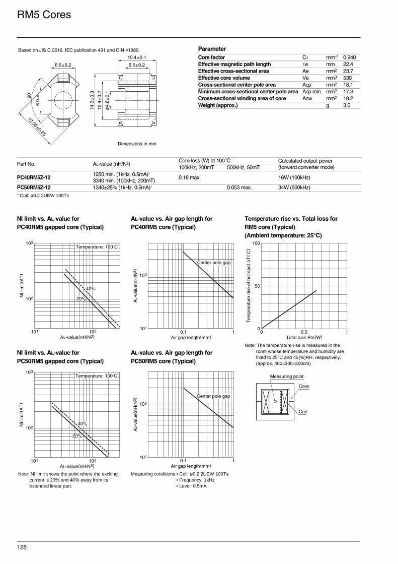
128
RM5 Cores
∗ Coil: ø0.2 2UEW 100Ts
NI limit vs. AL-value for AL-value vs. Air gap length for Temperature rise vs. Total loss forPC40RM5 gapped core (Typical) PC40RM5 core (Typical) RM5 core (Typical)
(Ambient temperature: 25°C)
NI limit vs. AL-value for AL-value vs. Air gap length forPC50RM5 gapped core (Typical) PC50RM5 core (Typical)
Part No. AL-value (nH/N2)Core loss (W) at 100°C Calculated output power
(forward converter mode)100kHz, 200mT 500kHz, 50mT
PC40RM5Z-121250 min. (1kHz, 0.5mA)∗
3340 min. (100kHz, 200mT)0.18 max. 16W (100kHz)
PC50RM5Z-12 1340±25% (1kHz, 0.5mA)∗ 0.053 max. 34W (500kHz)
ParameterCore factor C1 mm–1 0.940Effective magnetic path length e mm 22.4Effective cross-sectional area Ae mm2 23.7Effective core volume Ve mm3 530Cross-sectional center pole area Acp mm2 18.1Minimum cross-sectional center pole area Acp min. mm2 17.3Cross-sectional winding area of core Acw mm2 18.2Weight (approx.) g 3.0
12.05±0.25
Dimensions in mm
6.6±0.2
10.4±0.1
6.5±0.2
14.3
±0.
3
10.4
±0.
2
ø4.
8±
0.1
6.0–
090˚
Based on JIS C 2516, IEC publication 431 and DIN 41980.
Note: The temperature rise is measured in the room whose temperature and humidity are fixed to 25°C and 45(%)RH. respectively. (approx. 400×300×300cm)
102
103
NI l
imit(
AT
)
AL-value(nH/N2)102101
40%
20%
Temperature: 100˚C
102
101
AL-
valu
e(nH
/N2 )
Air gap length(mm)10.1
Center pole gap
0
50
100T
empe
ratu
re r
ise
of h
ot s
pot ∆
T( ˚
C)
Total loss Pm(W)0 10.5
Measuring point
Coil
Core
Note: NI limit shows the point where the exciting current is 20% and 40% away from its extended linear part.
Measuring conditions • Coil: ø0.2 2UEW 100Ts • Frequency: 1kHz• Level: 0.5mA
102
103
NI l
imit(
AT
)
AL-value(nH/N2)102101
40%
20%
Temperature: 100˚C
102
101
AL-
valu
e(nH
/N2 )
Air gap length(mm)10.1
Center pole gap

129
RM6 Cores
∗ Coil: ø0.26 2UEW 100Ts
NI limit vs. AL-value for AL-value vs. Air gap length for Temperature rise vs. Total loss forPC40RM6 gapped core (Typical) PC40RM6 core (Typical) RM6 core (Typical)
(Ambient temperature: 25°C)
NI limit vs. AL-value for AL-value vs. Air gap length forPC50RM6 gapped core (Typical) PC50RM6 core (Typical)
Part No. AL-value (nH/N2)Core loss (W) at 100°C Calculated output power
(forward converter mode)100kHz, 200mT 500kHz, 50mT
PC40RM6Z-121830 min. (1kHz, 0.5mA)∗
4030 min. (100kHz, 200mT)0.41 max. 27W (100kHz)
PC50RM6Z-12 1700±25% (1kHz, 0.5mA)∗ 0.11 max. 55W (500kHz)
ParameterCore factor C1 mm–1 0.781Effective magnetic path length e mm 28.6Effective cross-sectional area Ae mm2 36.6Effective core volume Ve mm3 1050Cross-sectional center pole area Acp mm2 31.2Minimum cross-sectional center pole area Acp min. mm2 30.2Cross-sectional winding area of core Acw mm2 26.0Weight (approx.) g 5.5
14.4±0.3
Dimensions in mm
8.0±0.2
12.4±0.1
8.2±0.2
17.6
±0.
3
12.6
5±
0.25
ø6.
3±
0.1
8.4–
0150˚
Based on JIS C 2516, IEC publication 431 and DIN 41980.
Note: The temperature rise is measured in the room whose temperature and humidity are fixed to 25°C and 45(%)RH. respectively. (approx. 400×300×300cm)
102
103
NI l
imit(
AT
)
AL-value(nH/N2)102101
40%
20%
Temperature: 100˚C
102
101
AL-
valu
e(nH
/N2 )
Air gap length(mm)10.1
Center pole gap
0
50
100
Tem
pera
ture
ris
e of
hot
spo
t ∆T
( ˚C
)
Total loss Pm(W)0 10.5
Measuring point
Coil
Core
Note: NI limit shows the point where the exciting current is 20% and 40% away from its extended linear part.
Measuring conditions • Coil: ø0.26 2UEW 100Ts • Frequency: 1kHz• Level: 0.5mA
102
103
NI l
imit(
AT
)
AL-value(nH/N2)102101
40%
20%
Temperature: 100˚C
102
101
AL-
valu
e(nH
/N2 )
Air gap length(mm)10.1
Center pole gap

130
RM8 Cores
∗ Coil: ø0.4 2UEW 100Ts
NI limit vs. AL-value for AL-value vs. Air gap length for Temperature rise vs. Total loss forPC40RM8 gapped core (Typical) PC40RM8 core (Typical) RM8 core (Typical)
(Ambient temperature: 25°C)
Part No. AL-value (nH/N2)Core loss (W) at 100°C Calculated output power
(forward converter mode)100kHz, 200mT
PC40RM8Z-121950 min. (1kHz, 0.5mA)∗
5290 min. (100kHz, 200mT)0.97 max. 67W (100kHz)
ParameterCore factor C1 mm–1 0.594Effective magnetic path length e mm 38Effective cross-sectional area Ae mm2 64Effective core volume Ve mm3 2430Cross-sectional center pole area Acp mm2 55.4Minimum cross-sectional center pole area Acp min. mm2 53.5Cross-sectional winding area of core Acw mm2 48.9Weight (approx.) g 13
19.35±0.35
Dimensions in mm
5.1±0.1
10.8±0.2 16.4±0.1
11.0±0.2
22.7
5±
0.45
17.3
±0.
3
ø8.
4±
0.15
4.0
9.8–
090˚
Based on JIS C 2516, IEC publication 431 and DIN 41980.
Note: NI limit shows the point where the exciting current is 20% and 40% away from its extended linear part.
Measuring conditions • Coil: ø0.4 2UEW 100Ts • Frequency: 1kHz• Level: 0.5mA
Note: The temperature rise is measured in the room whose temperature and humidity are fixed to 25°C and 45(%)RH. respectively. (approx. 400×300×300cm)
Measuring point
Coil
Core
102
103
NI l
imit(
AT
)
AL-value(nH/N2)103102
40%
20%
Temperature: 100˚C
103
102
AL-
valu
e(nH
/N2 )
Air gap length(mm)10.1
Center pole gap
0
50
100
Tem
pera
ture
ris
e of
hot
spo
t ∆T
( ˚C
)
Total loss Pm(W)0 21

131
RM10 Cores
∗ Coil: ø0.4 2UEW 100Ts
NI limit vs. AL-value for AL-value vs. Air gap length for Temperature rise vs. Total loss forPC40RM10 gapped core (Typical) PC40RM10 core (Typical) RM10 core (Typical)
(Ambient temperature: 25°C)
Part No. AL-value (nH/N2)Core loss (W) at 100°C Calculated output power
(forward converter mode)100kHz, 200mT
PC40RM10Z-123630 min. (1kHz, 0.5mA)∗
7000 min. (100kHz, 200mT)1.8 max. 130W (100kHz)
ParameterCore factor C1 mm–1 0.450Effective magnetic path length e mm 44.0Effective cross-sectional area Ae mm2 98.0Effective core volume Ve mm3 4310Cross-sectional center pole area Acp mm2 89.9Minimum cross-sectional center pole area Acp min. mm2 86.6Cross-sectional winding area of core Acw mm2 69.5Weight (approx.) g 23
24.15±0.55
Dimensions in mm
5.1±0.1
13.25±0.25 18.6±0.1
12.7±0.3
27.8
5±
0.65
21.6
5±
0.45
3
ø10
.7±
0.2
11.3
–090
˚Based on JIS C 2516, IEC publication 431 and DIN 41980.
Note: NI limit shows the point where the exciting current is 20% and 40% away from its extended linear part.
Measuring conditions • Coil: ø0.4 2UEW 100Ts • Frequency: 1kHz• Level: 0.5mA
Note: The temperature rise is measured in the room whose temperature and humidity are fixed to 25°C and 45(%)RH. respectively. (approx. 400×300×300cm)
102
103
NI l
imit(
AT
)
AL-value(nH/N2)103102
40%
20%
Temperature: 100˚C
103
102
AL-
valu
e(nH
/N2 )
Air gap length(mm)10.1
Center pole gap
Spacer gap
0
50
100
Tem
pera
ture
ris
e of
hot
spo
t ∆T
( ˚C
)
Total loss Pm(W)0 21
Measuring point
Coil
Core

132
RM12 Cores
∗ Coil: ø0.4 2UEW 100Ts
NI limit vs. AL-value for AL-value vs. Air gap length for Temperature rise vs. Total loss forPC40RM12 gapped core (Typical) PC40RM12 core (Typical) RM12 core (Typical)
(Ambient temperature: 25°C)
Part No. AL-value (nH/N2)Core loss (W) at 100°C Calculated output power
(forward converter mode)100kHz, 200mT
PC40RM12Z-124150 min. (1kHz, 0.5mA)∗
9290 min. (100kHz, 200mT)3.3 max. 344W (100kHz)
ParameterCore factor C1 mm–1 0.406Effective magnetic path length e mm 56.9Effective cross-sectional area Ae mm2 140Effective core volume Ve mm3 7960Cross-sectional center pole area Acp mm2 125Minimum cross-sectional center pole area Acp min. mm2 121Cross-sectional winding area of core Acw mm2 110Weight (approx.) g 42
29.25±0.55
Dimensions in mm
5.5±0.1
16.0±0.3 23.5±0.1
17.1±0.3
36.7
5±
0.65
25.5
±0.
5
8.69
ø12
.6±
0.2
12.9
–0
90˚
20.6±0.2
Based on JIS C 2516.
Note: NI limit shows the point where the exciting current is 20% and 40% away from its extended linear part.
Measuring conditions • Coil: ø0.4 2UEW 100Ts • Frequency: 1kHz• Level: 0.5mA
Note: The temperature rise is measured in the room whose temperature and humidity are fixed to 25°C and 45(%)RH. respectively. (approx. 400×300×300cm)
102
103
NI l
imit(
AT
)
AL-value(nH/N2)103102
40%
20%
Temperature: 100˚C
103
102
AL-
valu
e(nH
/N2 )
Air gap length(mm)10.1
Center pole gap
Spacer gap
0
50
100
Tem
pera
ture
ris
e of
hot
spo
t ∆T
( ˚C
)
Total loss Pm(W)0 54321
Measuring point
Coil
Core

133
RM14 Cores
∗ Coil: ø0.4 2UEW 100Ts
NI limit vs. AL-value for AL-value vs. Air gap length for Temperature rise vs. Total loss forPC40RM14 gapped core (Typical) PC40RM14 core (Typical) RM14 core (Typical)
(Ambient temperature: 25°C)
Part No. AL-value (nH/N2)Core loss (W) at 100°C Calculated output power
(forward converter mode)100kHz, 200mT
PC40RM14Z-124600 min. (1kHz, 0.5mA)∗
9590 min. (100kHz, 200mT)4.75 max. 376W (100kHz)
ParameterCore factor C1 mm–1 0.393Effective magnetic path length e mm 70.0Effective cross-sectional area Ae mm2 178Effective core volume Ve mm3 12500Cross-sectional center pole area Acp mm2 171Minimum cross-sectional center pole area Acp min. mm2 165Cross-sectional winding area of core Acw mm2 155Weight (approx.) g 70
34.2±0.5
Dimensions in mm
18.7±0.3 28.8±0.2
21.1±0.3 1.5
41.6
±0.
6
29.5
±0.
5
12.55
ø14
.75
±0.
25
17–
0
90˚
25.8±0.25
5.7±0.1
Based on JIS C 2516, IEC publication 431 and DIN 41980.
Note: NI limit shows the point where the exciting current is 20% and 40% away from its extended linear part.
Measuring conditions • Coil: ø0.4 2UEW 100Ts • Frequency: 1kHz• Level: 0.5mA
Note: The temperature rise is measured in the room whose temperature and humidity are fixed to 25°C and 45(%)RH. respectively. (approx. 400×300×300cm)
Measuring point
Coil
Core
102
103
NI l
imit(
AT
)
AL-value(nH/N2)103102
40%
20%
Temperature: 100˚C
103
102
AL-
valu
e(nH
/N2 )
Air gap length(mm)10.1
Center pole gap
0
50
100
Tem
pera
ture
ris
e of
hot
spo
t ∆T
( ˚C
)
Total loss Pm(W)0 54321

134
EPC10 Cores
∗ Coil: ø0.1 2UEW 100Ts
NI limit vs. AL-value for AL-value vs. Air gap length for Temperature rise vs. Total loss forPC44EPC10 gapped core (Typical) PC44EPC10 core (Typical) EPC10 core (Typical)
(Ambient temperature: 25°C)
NI limit vs. AL-value for AL-value vs. Air gap length forPC50EPC10 gapped core (Typical) PC50EPC10 core (Typical)
Part No. AL-value (nH/N2)Core loss (W) at 100°C Calculated output power
(forward converter mode)100kHz, 200mT 500kHz, 50mTPC44EPC10-Z 1000±25% (1kHz, 0.5mA)∗ 0.072 max. 5.4W (100kHz)PC50EPC10-Z 660±25% (1kHz, 0.5mA)∗ 0.025 max. 13W (500kHz)
ParameterCore factor C1 mm–1 1.89Effective magnetic path length e mm 17.8Effective cross-sectional area Ae mm2 9.39Effective core volume Ve mm3 167Cross-sectional center pole area Acp mm2 8.73Minimum cross-sectional area Acp min. mm2 8.13Cross-sectional winding area of core Acw mm2 7.69Weight (approx.) g 1.1
7.6min.
10.2±0.2
5.0±0.1
5.3min.
2.65±0.1
4.05±0.1
3.4
±0.1
1.9
±0.1
Dimensions in mm
Note: The temperature rise is measured in the room whose temperature and humidity are fixed to 25°C and 45(%)RH. respectively. (approx. 400×300×300cm)
101
102
NI l
imit(
AT
)
AL-value(nH/N2)102101
40%
20%
Temperature: 100˚C103
101
102
AL-
valu
e(nH
/N2 )
Air gap length(mm)10.1
Center pole gap
0
50
100
Tem
pera
ture
ris
e of
hot
spo
t ∆T
( ˚C
)
Total loss Pm(W)0 10.5
Measuring point
Coil
Core
Note: NI limit shows the point where the exciting current is 20% and 40% away from its extended linear part.
Measuring conditions • Coil: ø0.1 2UEW 100Ts • Frequency: 1kHz• Level: 0.5mA
102
103
NI l
imit(
AT
)
AL-value(nH/N2)102101
40%
20%
Temperature: 100˚C103
101
102
AL-
valu
e(nH
/N2 )
Air gap length(mm)10.1
Center pole gap

135
EPC13 Cores
∗ Coil: ø0.2 2UEW 100Ts
NI limit vs. AL-value for AL-value vs. Air gap length for Temperature rise vs. Total loss forPC44EPC13 gapped core (Typical) PC44EPC13 core (Typical) EPC13 core (Typical)
(Ambient temperature: 25°C)
NI limit vs. AL-value for AL-value vs. Air gap length forPC50EPC13 gapped core (Typical) PC50EPC13 core (Typical)
Part No. AL-value (nH/N2)Core loss (W) at 100°C Calculated output power
(forward converter mode)100kHz, 200mT 500kHz, 50mTPC44EPC13-Z 870±25% (1kHz, 0.5mA)∗ 0.14 max. 8W (100kHz)PC50EPC13-Z 560±25% (1kHz, 0.5mA)∗ 0.039 max. 19W (500kHz)
ParameterCore factor C1 mm–1 2.45Effective magnetic path length e mm 30.6Effective cross-sectional area Ae mm2 12.5Effective core volume Ve mm3 382Cross-sectional center pole area Acp mm2 10.6Minimum cross-sectional area Acp min. mm2 9.71Cross-sectional winding area of core Acw mm2 23.0Weight (approx.) g 2.1
10.5min.
13.3±0.3
5.6±0.15 4.5±0.2
6.6±0.2
4.6
±0.1
5
2.05
±0.1
Dimensions in mm
8.3min.
Note: The temperature rise is measured in the room whose temperature and humidity are fixed to 25°C and 45(%)RH. respectively. (approx. 400×300×300cm)
102
103
NI l
imit(
AT
)
AL-value(nH/N2)102101
40%
20%
Temperature: 100˚C103
101
102
AL-
valu
e(nH
/N2 )
Air gap length(mm)10.1
Center pole gap
0
50
100
Tem
pera
ture
ris
e of
hot
spo
t ∆T
( ˚C
)
Total loss Pm(W)0 10.5
Measuring point
Coil
Core
Note: NI limit shows the point where the exciting current is 20% and 40% away from its extended linear part.
Measuring conditions • Coil: ø0.2 2UEW 100Ts • Frequency: 1kHz• Level: 0.5mA
101
102
NI l
imit(
AT
)
AL-value(nH/N2)102101
40%
20%
Temperature: 100˚C103
101
102
AL-
valu
e(nH
/N2 )
Air gap length(mm)10.1
Center pole gap

136
EPC17 Cores
∗ Coil: ø0.2 2UEW 100Ts
NI limit vs. AL-value for AL-value vs. Air gap length for Temperature rise vs. Total loss forPC44EPC17 gapped core (Typical) PC44EPC17 core (Typical) EPC17 core (Typical)
(Ambient temperature: 25°C)
NI limit vs. AL-value for AL-value vs. Air gap length forPC50EPC17 gapped core (Typical) PC50EPC17 core (Typical)
Part No. AL-value (nH/N2)Core loss (W) at 100°C Calculated output power
(forward converter mode)100kHz, 200mT 500kHz, 50mTPC44EPC17-Z 1150±25% (1kHz, 0.5mA)∗ 0.35 max. 20W (100kHz)PC50EPC17-Z 740±25% (1kHz, 0.5mA)∗ 0.10 max. 35W (500kHz)
ParameterCore factor C1 mm–1 1.76Effective magnetic path length e mm 40.2Effective cross-sectional area Ae mm2 22.8Effective core volume Ve mm3 917Cross-sectional center pole area Acp mm2 19.9Minimum cross-sectional area Acp min. mm2 19.9Cross-sectional winding area of core Acw mm2 18.7Weight (approx.) g 4.5
14.3min.
17.6±0.4
7.7±0.15 6.05±0.2
8.55±0.2
6.0
±0.1
5
2.8
±0.1
Dimensions in mm
11.5min.
Note: The temperature rise is measured in the room whose temperature and humidity are fixed to 25°C and 45(%)RH. respectively. (approx. 400×300×300cm)
102
103
NI l
imit(
AT
)
AL-value(nH/N2)102101
40%
20%
Temperature: 100˚C103
101
102
AL-
valu
e(nH
/N2 )
Air gap length(mm)10.1
Center pole gap
0
50
100
Tem
pera
ture
ris
e of
hot
spo
t ∆T
( ˚C
)
Total loss Pm(W)0 1.5 2.51 20.5
Measuring point
Coil
Core
Note: NI limit shows the point where the exciting current is 20% and 40% away from its extended linear part.
Measuring conditions • Coil: ø0.2 2UEW 100Ts • Frequency: 1kHz• Level: 0.5mA
103
101
102
AL-
valu
e(nH
/N2 )
Air gap length(mm)10.1
Center pole gap
101
102
NI l
imit(
AT
)
AL-value(nH/N2)102101
40%
20%
Temperature: 100˚C

137
EPC19 Cores
∗ Coil: ø0.2 2UEW 100Ts
NI limit vs. AL-value for AL-value vs. Air gap length for Temperature rise vs. Total loss forPC44EPC19 gapped core (Typical) PC44EPC19 core (Typical) EPC19 core (Typical)
(Ambient temperature: 25°C)
NI limit vs. AL-value for AL-value vs. Air gap length forPC50EPC19 gapped core (Typical) PC50EPC19 core (Typical)
Part No. AL-value (nH/N2)Core loss (W) at 100°C Calculated output power
(forward converter mode)100kHz, 200mT 500kHz, 50mTPC44EPC19-Z 940±25% (1kHz, 0.5mA)∗ 0.4 max. 27W (100kHz)PC50EPC19-Z 680±25% (1kHz, 0.5mA)∗ 0.12 max. 55W (500kHz)
ParameterCore factor C1 mm–1 2.03Effective magnetic path length e mm 46.1Effective cross-sectional area Ae mm2 22.7Effective core volume Ve mm3 1050Cross-sectional center pole area Acp mm2 19.9Minimum cross-sectional area Acp min. mm2 18.7Cross-sectional winding area of core Acw mm2 54.4Weight (approx.) g 5.3
15.8min.
19.1±0.4
8.5±0.15 7.25±0.2
9.75±0.2
6.0
±0.1
5
2.5
±0.1
Dimensions in mm
13.1min.
Note: The temperature rise is measured in the room whose temperature and humidity are fixed to 25°C and 45(%)RH. respectively. (approx. 400×300×300cm)
102
103
NI l
imit(
AT
)
AL-value(nH/N2)102101
40%
20%
Temperature: 100˚C103
101
102
AL-
valu
e(nH
/N2 )
Air gap length(mm)10.1
Center pole gap
0
50
100
Tem
pera
ture
ris
e of
hot
spo
t ∆T
( ˚C
)
Total loss Pm(W)0 1.5 2.51 20.5
Measuring point
Coil
Core
Note: NI limit shows the point where the exciting current is 20% and 40% away from its extended linear part.
Measuring conditions • Coil: ø0.2 2UEW 100Ts • Frequency: 1kHz• Level: 0.5mA
101
102
NI l
imit(
AT
)
AL-value(nH/N2)102101
40%
20%
Temperature: 100˚C
103
101
102
AL-
valu
e(nH
/N2 )
Air gap length(mm)10.1
Center pole gap

138
EPC25 Cores
∗ Coil: ø0.2 2UEW 100Ts
NI limit vs. AL-value for AL-value vs. Air gap length for Temperature rise vs. Total loss forPC44EPC25 gapped core (Typical) PC44EPC25 core (Typical) EPC25 core (Typical)
(Ambient temperature: 25°C)
NI limit vs. AL-value for AL-value vs. Air gap length forPC50EPC25 gapped core (Typical) PC50EPC25 core (Typical)
Part No. AL-value (nH/N2)Core loss (W) at 100°C Calculated output power
(forward converter mode)100kHz, 200mT 500kHz, 50mTPC44EPC25-Z 1560±25% (1kHz, 0.5mA)∗ 1.11 max. 63W (100kHz)PC50EPC25-Z 1080±25% (1kHz, 0.5mA)∗ 0.32 max. 127W (500kHz)
ParameterCore factor C1 mm–1 1.28Effective magnetic path length e mm 59.2Effective cross-sectional area Ae mm2 46.4Effective core volume Ve mm3 2750Cross-sectional center pole area Acp mm2 42.6Minimum cross-sectional area Acp min. mm2 40.6Cross-sectional winding area of core Acw mm2 85.5Weight (approx.) g 13
20.65min.
25.1±0.5
11.5±0.2 9.0±0.3
12.5±0.28.
0±0
.2
4.0
±0.1
Dimensions in mm
17.0min.
Note: The temperature rise is measured in the room whose temperature and humidity are fixed to 25°C and 45(%)RH. respectively. (approx. 400×300×300cm)
102
103
NI l
imit(
AT
)
AL-value(nH/N2)103102
40%
20%
Temperature: 100˚C103
101
102
AL-
valu
e(nH
/N2 )
Air gap length(mm)10.1
Center pole gap
0
50
100
Tem
pera
ture
ris
e of
hot
spo
t ∆T
( ˚C
)
Total loss Pm(W)0 1.5 2.51 20.5
Measuring point
Coil
Core
Note: NI limit shows the point where the exciting current is 20% and 40% away from its extended linear part.
Measuring conditions • Coil: ø0.2 2UEW 100Ts • Frequency: 1kHz• Level: 0.5mA
102
103
NI l
imit(
AT
)
AL-value(nH/N2)103102
40%
20%
Temperature: 100˚C103
101
102
AL-
valu
e(nH
/N2 )
Air gap length(mm)10.1
Center pole gap

139
EPC25B Cores
∗ Coil: ø0.23 2UEW 100Ts
NI limit vs. AL-value for AL-value vs. Air gap length for Temperature rise vs. Total loss forPC44EPC25B gapped core (Typical) PC44EPC25B core (Typical) EPC25B core (Typical)
(Ambient temperature: 25°C)
NI limit vs. AL-value for AL-value vs. Air gap length forPC50EPC25B gapped core (Typical) PC50EPC25B core (Typical)
Part No. AL-value (nH/N2)Core loss (W) at 100°C Calculated output power
(forward converter mode)100kHz, 200mT 500kHz, 50mTPC44EPC25B-Z 1560±25% (1kHz, 0.5mA)∗ 0.65 max. 45W (100kHz)PC50EPC25B-Z 1080±25% (1kHz, 0.5mA)∗ 0.22 max. 87W (500kHz)
ParameterCore factor C1 mm–1 1.39Effective magnetic path length e mm 46.2Effective cross-sectional area Ae mm2 33.3Effective core volume Ve mm3 1540Cross-sectional center pole area Acp mm2 32.4Minimum cross-sectional area Acp min. mm2 30.3Cross-sectional winding area of core Acw mm2 62.1Weight (approx.) g 11
20.4min.
25.1±0.5
13.8±0.28.78±0.1511.43±0.15
6.5
±0.2
2.5
±0.1
5Dimensions in mm
16.5min.
Note: The temperature rise is measured in the room whose temperature and humidity are fixed to 25°C and 45(%)RH. respectively. (approx. 400×300×300cm)
Measuring point
Coil
Core
102
103
NI l
imit(
AT
)
AL-value(nH/N2)102101
40%
20%
Temperature: 100˚C103
101
102
AL-
valu
e(nH
/N2 )
Air gap length(mm)10.1
Center pole gap
0
50
100
Tem
pera
ture
ris
e of
hot
spo
t ∆T
( ˚C
)
Total loss Pm(W)0 1.5 2.51 20.5
Note: NI limit shows the point where the exciting current is 20% and 40% away from its extended linear part.
Measuring conditions • Coil: ø0.23 2UEW 100Ts • Frequency: 1kHz• Level: 0.5mA
102
103
NI l
imit(
AT
)
AL-value(nH/N2)102101
40%
20%
Temperature: 100˚C103
101
102
AL-
valu
e(nH
/N2 )
Air gap length(mm)10.1
Center pole gap
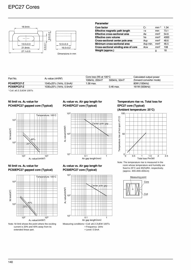
140
EPC27 Cores
∗ Coil: ø0.3 2UEW 100Ts
NI limit vs. AL-value for AL-value vs. Air gap length for Temperature rise vs. Total loss forPC44EPC27 gapped core (Typical) PC44EPC27 core (Typical) EPC27 core (Typical)
(Ambient temperature: 25°C)
NI limit vs. AL-value for AL-value vs. Air gap length forPC50EPC27 gapped core (Typical) PC50EPC27 core (Typical)
Part No. AL-value (nH/N2)Core loss (W) at 100°C Calculated output power
(forward converter mode)100kHz, 200mT 500kHz, 50mTPC44EPC27-Z 1540±25% (1kHz, 0.5mA)∗ 1.56 max. 80W (100kHz)PC50EPC27-Z 1030±25% (1kHz, 0.5mA)∗ 0.46 max. 161W (500kHz)
ParameterCore factor C1 mm–1 1.34Effective magnetic path length e mm 73.1Effective cross-sectional area Ae mm2 54.6Effective core volume Ve mm3 4000Cross-sectional center pole area Acp mm2 48.6Minimum cross-sectional area Acp min. mm2 46.5Cross-sectional winding area of core Acw mm2 108Weight (approx.) g 18
21.6min.
27.1±0.5
13.0±0.3 12.0±0.3
16.0±0.28.
0±0
.2
4.0
±0.1
Dimensions in mm
18.5min.
Note: The temperature rise is measured in the room whose temperature and humidity are fixed to 25°C and 45(%)RH. respectively. (approx. 400×300×300cm)
102
103
NI l
imit(
AT
)
AL-value(nH/N2)103102
40%
20%
Temperature: 100˚C103
101
102
AL-
valu
e(nH
/N2 )
Air gap length(mm)10.1
Center pole gap
0
50
100
Tem
pera
ture
ris
e of
hot
spo
t ∆T
( ˚C
)
Total loss Pm(W)0 1.5 2.51 20.5
Measuring point
Coil
Core
Note: NI limit shows the point where the exciting current is 20% and 40% away from its extended linear part.
Measuring conditions • Coil: ø0.3 2UEW 100Ts • Frequency: 1kHz• Level: 0.5mA
102
103
NI l
imit(
AT
)
AL-value(nH/N2)103102
40%
20%
Temperature: 100˚C103
101
102
AL-
valu
e(nH
/N2 )
Air gap length(mm)10.1
Center pole gap

141
EPC27N Cores
∗ Coil: ø0.3 2UEW 100Ts
NI limit vs. AL-value for AL-value vs. Air gap length for Temperature rise vs. Total loss forPC44EPC27N gapped core (Typical) PC44EPC27N core (Typical) EPC27N core (Typical)
(Ambient temperature: 25°C)
Part No. AL-value (nH/N2)Core loss (W) at 100°C Calculated output power
(forward converter mode)100kHz, 200mTPC44EPC27N-Z 1400±25% (1kHz, 0.5mA)∗ 0.73 max. 43W (100kHz)
ParameterCore factor C1 mm–1 1.70Effective magnetic path length e mm 55.9Effective cross-sectional area Ae mm2 33.0Effective core volume Ve mm3 1840Cross-sectional center pole area Acp mm2 29.7Minimum cross-sectional center pole area Acp min. mm2 29.7Cross-sectional winding area of core Acw mm2 60.4Weight (approx.) g 10
20.8min.
27.0±0.4
13.85±0.15 8.5±0.1
13.0±0.1
5.1±
0.1
2.2
±0.1
Dimensions in mm
19.0min.
Note: NI limit shows the point where the exciting current is 20% and 40% away from its extended linear part.
Measuring conditions • Coil: ø0.3 2UEW 100Ts • Frequency: 1kHz• Level: 0.5mA
Note: The temperature rise is measured in the room whose temperature and humidity are fixed to 25°C and 45(%)RH. respectively. (approx. 400×300×300cm)
Measuring point
Coil
Core
101
102
NI l
imit(
AT
)
AL-value(nH/N2)103102
40%
20%
Temperature: 100˚C103
101
102
AL-
valu
e(nH
/N2 )
Air gap length(mm)10.1
Center pole gap
0
50
100
Tem
pera
ture
ris
e of
hot
spo
t ∆T
( ˚C
)
Total loss Pm(W)0 1.5 2.51 20.5

142
EPC30 Cores
∗ Coil: ø0.3 2UEW 100Ts
NI limit vs. AL-value for AL-value vs. Air gap length for Temperature rise vs. Total loss forPC44EPC30 gapped core (Typical) PC44EPC30 core (Typical) EPC30 core (Typical)
(Ambient temperature: 25°C)
NI limit vs. AL-value for AL-value vs. Air gap length forPC50EPC30 gapped core (Typical) PC50EPC30 core (Typical)
Part No. AL-value (nH/N2)Core loss (W) at 100°C Calculated output power
(forward converter mode)100kHz, 200mT 500kHz, 50mTPC44EPC30-Z 1570±25% (1kHz, 0.5mA)∗ 2.03 max. 85W (100kHz)PC50EPC30-Z 1060±25% (1kHz, 0.5mA)∗ 0.58 max. 180W (500kHz)
ParameterCore factor C1 mm–1 1.34Effective magnetic path length e mm 81.6Effective cross-sectional area Ae mm2 61.0Effective core volume Ve mm3 4980Cross-sectional center pole area Acp mm2 56.6Minimum cross-sectional area Acp min. mm2 54.3Cross-sectional winding area of core Acw mm2 117Weight (approx.) g 23
23.6min.
30.1±0.5
15.0±0.3 13.0±0.3
17.5±0.2
8.0
±0.2
4.0
±0.1
Dimensions in mm
20.0min.
Note: The temperature rise is measured in the room whose temperature and humidity are fixed to 25°C and 45(%)RH. respectively. (approx. 400×300×300cm)
Measuring point
Coil
Core
102
103
NI l
imit(
AT
)
AL-value(nH/N2)103102
40%
20%
Temperature: 100˚C103
101
102
AL-
valu
e(nH
/N2 )
Air gap length(mm)10.1
Center pole gap
0
50
100
Tem
pera
ture
ris
e of
hot
spo
t ∆T
( ˚C
)
Total loss Pm(W)0 1.5 2.51 20.5
Note: NI limit shows the point where the exciting current is 20% and 40% away from its extended linear part.
Measuring conditions • Coil: ø0.3 2UEW 100Ts • Frequency: 1kHz• Level: 0.5mA
102
103
NI l
imit(
AT
)
AL-value(nH/N2)103102
40%
20%
Temperature: 100˚C103
101
102
AL-
valu
e(nH
/N2 )
Air gap length(mm)10.1
Center pole gap

143
Maximum Number of Turns on Bobbins
EI and EE SeriesEER SeriesEC and ETD SeriesPQ SeriesLP SeriesEP SeriesRM SeriesSMD SeriesEPC and EEM SeriesWire Table

144
Maximum Number of Turns on Bobbins
Maximum Number of Turns on BobbinsEI and EE Series (without terminal pin) EER Series
EI and EE Series (with terminal pin) EC and ETD Series
102
101
103
104
N( t
urns
)
Overall diameter of insulated wire(ømm)include insulation thickness
AWG value
10.50.1
BE62.3-1112CPHFR
BE-60-5112
BE-30-5112
BE-22-5116
BE-19-5116
BE-50-5112
BE-40-5112BE50.3-1112CPHFR
38 36 34 32 30 28 26 24 22 20 18
102
101
103
104
N( t
urns
)
Overall diameter of insulated wire(ømm)include insulation thickness
AWG value
10.50.1
BEER28
BEER25.5
38 36 34 32 30 28 26 24 22 20 18
BEER40
BEER49
BEER42/20
BEER28LBEER35
BE12.5-1110CPFR
BE10-118CPSFR
102
101
103
104
N( t
urns
)
Overall diameter of insulated wire(ømm)include insulation thickness
AWG value
10.50.1
38 36 34 32 30 28 26 24 22 20 18
BE60-1112CPFRBE50-1112CPFR
BE40-1112CPFR
BE30-1110CPFR
BE33-1112CPLFRBE35-1112CPLFR
BE25-118CPFR
BE22/19/6-118CPFR
BES16-1110CPSFRBE19-116CPFRBE28-1110CPLFR
BE16-116CPFR
BE22-118CPFR
BE13-1110CPSFR 102
101
103
104
N( t
urns
)
Overall diameter of insulated wire(ømm)include insulation thickness
AWG value
10.50.1
38 36 34 32 30 28 26 24 22 20 18
BETD19-1111CPHFR
BETD24-1112CPHFR
BEC70-5116
BEC90-0112

145
PQ Series EP Series
LP Series RM Series
102
101
103
104
N( t
urns
)
Overall diameter of insulated wire(ømm)include insulation thickness
AWG value
10.50.1
38 36 34 32 30 28 26 24 22 20 18
BPQ50/50
BPQ35/35BPQ32/30
BPQ26/25BPQ32/20BPQ20/20BPQ26/20BPQ20/16
BPQ40/40
BEP7
102
101
103
104
N( t
urns
)
Overall diameter of insulated wire(ømm)include insulation thickness
AWG value
10.50.1
38 36 34 32 30 28 26 24 22 20 18
BEP20
BEP17
BEP10
BEP13
102
101
103
104
N( t
urns
)
Overall diameter of insulated wire(ømm)include insulation thickness
AWG value
10.50.1
38 36 34 32 30 28 26 24 22 20 18
BLP23/8-018CPLFR
BLP22/13-1110CPLFRBLP22/13-018CPLFR
BLP32/13-018CPLFRBLP32/13-110CPLFR
BRM4
102
101
103
104
N( t
urns
)
Overall diameter of insulated wire(ømm)include insulation thickness
AWG value
10.50.1
38 36 34 32 30 28 26 24 22 20 18
BRM8
BRM10
BRM12
BRM14
BRM6
BRM5

146
Maximum Number of Turns on Bobbins
SMD Series
EPC and EEM Series
BER14.5/6-1110GAFR
102
101
103
104
N( t
urns
)
Overall diameter of insulated wire(ømm)include insulation thickness
AWG value
0.1 0.20.050.01
50 48 4446 42 40 38 36 34 32
BE8.9/8-11GFR
BER9.5/5-118GAFRBER11/5-1110GAFR
BE-5-916FBER11/3.9-1110GAFR
BEPC10-118GAFR
102
101
103
104
N( t
urns
)
Overall diameter of insulated wire(ømm)include insulation thickness
AWG value
10.50.1
38 36 34 32 30 28 26 24 22 20 18
BEM12.7-118GAFR
BEPC13-1110CPHFRBEPC13-1110GAFR
BEPC30-1112CPHFRBEPC27-1111CPHFRBEPC25-1111CPHFR
BEPC25B-1111GAFRBEPC27N-1114CPHFR
BEPC19-1111CPHFRBEPC19-1110GAFRBEPC19-1110SAFR
BEPC17-1110CPHFRBEPC17-119GAFR

147
Wire Table
Wire TableAWG AWG dia.(mm) AWG area(mm2) Single dia.(mm) Single area(mm2) Heavy dia.(mm) Heavy area(mm2)40 0.078 0.0053 0.093 0.0068 0.100 0.007839 0.089 0.0066 0.104 0.0085 0.112 0.009938 0.102 0.0083 0.117 0.0108 0.126 0.012537 0.114 0.0105 0.131 0.0135 0.141 0.015636 0.127 0.0132 0.147 0.0169 0.158 0.019535 0.142 0.0166 0.164 0.0212 0.176 0.024334 0.160 0.0209 0.184 0.0265 0.196 0.030333 0.180 0.0264 0.205 0.0330 0.219 0.037632 0.203 0.0332 0.229 0.0412 0.244 0.046731 0.226 0.0418 0.256 0.0513 0.271 0.057830 0.254 0.0526 0.285 0.0640 0.302 0.071729 0.287 0.0663 0.319 0.0797 0.336 0.088828 0.320 0.0834 0.356 0.0993 0.374 0.109927 0.360 0.1050 0.397 0.1237 0.416 0.136226 0.404 0.1322 0.443 0.1542 0.464 0.168825 0.454 0.1664 0.495 0.1922 0.516 0.209324 0.510 0.2095 0.552 0.2397 0.575 0.259623 0.574 0.2638 0.617 0.2990 0.641 0.322222 0.642 0.3321 0.689 0.3731 0.714 0.400121 0.724 0.4181 0.770 0.4659 0.796 0.497220 0.812 0.5624 0.861 0.5820 0.887 0.618319 0.910 0.6627 0.962 0.7272 0.990 0.769318 1.024 0.8343 1.076 0.9092 1.104 0.957817 1.156 1.0504 1.203 1.1371 1.233 1.193316 1.298 1.3224 1.346 1.4228 1.376 1.487715 1.456 1.6648 1.506 1.7809 1.537 1.855914 1.634 2.0959 1.685 2.2301 1.717 2.316513 1.833 2.6386 1.886 2.7935 1.919 2.893112 2.057 3.3219 2.111 3.5006 2.145 3.615311 2.308 4.1821 2.364 4.3882 2.399 4.520110 2.589 5.2651 2.647 5.5024 2.683 5.65429 2.905 6.6285 2.964 6.9018 3.002 7.07638 3.260 8.3449 3.320 8.6594 3.359 8.85997 3.657 10.5059 3.720 10.8674 3.759 11.09776 4.104 13.2264 4.168 13.6419 4.208 13.9062