control components for vav terminal units – type compact
TRANSCRIPT

05/2015 – DE/en
Control componentsfor VAV terminal units Type Compact
1
Compact device for use with VAV terminal units ■ Controller, differential pressure transducer,
and actuator are fitted together in one casing ■ Volume flow rates min and max are factory set as parameters ■ Ideal for carrying out service from the switch cabinet or control panel ■ Change of parameters using adjustment devices ■ Suitable for constant and variable volume flows
as well as for min / max switching ■ Bus communication is possible due to MP bus or LonWorks interfaces
Compact 1.3 –
X X Compact testregistrierung
K 5 – 1.3 – 9
With service interface and bus communication facility
Control components for VAV terminal units General information
05/2015
Compact
– DE/en
1 Type Compact General information 1.3 – 10
Special information – BC0, BF0 1.3 – 12Special information – BL0 1.3 – 18Special information – XB0, XG0 1.3 – 21Special information – LN0, LY0 1.3 – 26
Application– Electronic volume flow controllers of Type Compact are compact, all-in-one
control devices for VAV terminal units– Dynamic differential pressure transducer,
electronic controller, and actuator are fitted together in one casing
– Suitable for different control tasks depending on how the input for the setpoint value signal
is used– The output signals of the room temperature
controller, central BMS, air quality controller or similar units control the volume flow rate
setpoint– Override control by means of switches or relays– Volume flow rate actual value is available as linear voltage signal– Controller parameters are factory set
Standard filtration in comfort air conditioning systems allows for use of the controller inthe supply air without additional dust protection. Since a partial volume flow is passed throughthe transducer in order to measure the volume flow rate, please note:
– With heavy dust levels in the room, suitable extract air filters must be provided.– If the air is polluted with fluff or sticky particles
or contains aggressive media, Compact controllers cannot be used
Commissioning– On-site adjusting is not required– Integration of voltage signals into the central BMS– If data transmission via bus interfaces is required, a system integrator should be
involved in commissioning
Basic information and nomenclature 1.5 – 1
Page
K 5 – 1.3 – 10
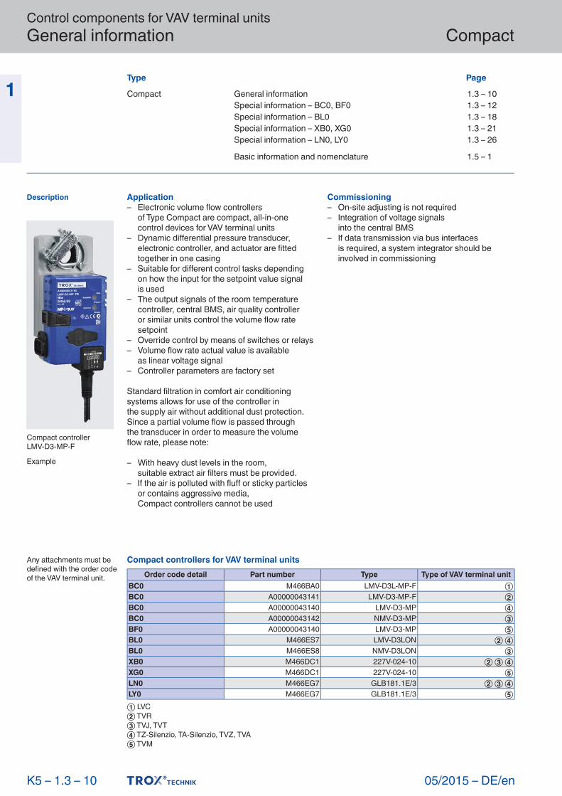
Description
Compact controllerLMV-D3- MP-F
Example
Any attachments must be defined with the order code of the VAV terminal unit.
Compact controllers for VAV terminal unitsOrder code detail Part number Type Type of VAV terminal unit
BC0 M466BA0 LMV-D3L-MP-F ①BC0 A00000043141 LMV-D3-MP-F ②BC0 A00000043140 LMV-D3-MP ④BC0 A00000043142 NMV-D3-MP ③BF0 A00000043140 LMV-D3-MP ⑤BL0 M466ES7 LMV-D3LON ② ④BL0 M466ES8 NMV-D3LON ③XB0 M466DC1 227V-024-10 ② ③ ④XG0 M466DC1 227V-024-10 ⑤LN0 M466EG7 GLB181.1E/3 ② ③ ④LY0 M466EG7 GLB181.1E/3 ⑤① LVC② TVR③ TVJ, TVT④ TZ-Silenzio, TA-Silenzio, TVZ, TVA⑤ TVM
Control components for VAV terminal units General information
05/2015 – DE/en
Compact
1 Functional descriptionThe volume flow rate is determined by measuring the differential pressure (effective pressure).For this purpose the VAV terminal unit is fittedwith a differential pressure sensor.The integral differental pressure transducer transforms the effective pressure into a voltage signal. The volume flow rate actual value is hence available as a voltage signal. The factory settingis such that 10 V DC always correspondsto the nominal volume flow rate (nom).The volume flow rate setpoint value comes froma higher-level controller (e.g. room temperature controller, air quality controller, central BMS)or from switch contacts. Variable volume flow control results in a value between min and max. It is possible to override the room temperature control, e.g. by a complete shut-off of the duct.The controller compares the volume flow rate setpoint value to the actual value and controlsthe integral actuator accordingly.Volume flow rate parameters and voltage ranges are factory stored in the controller. Changes on the customer's site can easily be carried out using an adjustment device, a notebook with service tool, or a bus interface.
Volume flow control– The volume flow controller works independent of the duct pressure– Differential pressure fluctuations do not result
in permanent volume flow rate changes– To prevent the control from becoming unstable,
a dead band is allowed within which the damper blade does not move.
K 5 – 1.3 – 11
Function
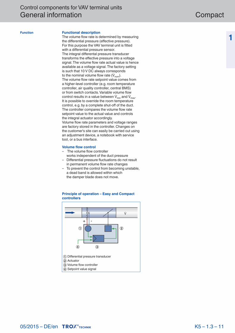
Principle of operation – Easy and Compact controllers
+ -
① Differential pressure transducer② Actuator③ Volume flow controller④ Setpoint value signal

Control components for VAV terminal units Special information – BC0, BF0
05/2015
Compact
– DE/en
1 Application– Electronic volume flow controller LMV-D3L-MP-
F, LMV-D3-MP, LMV-D3-MP-F or NMV-D3-MP as Compact controller
– Variable air or constant air volume flow control– The flow rate is measured using the dynamic
measurement principle– Voltage range for the actual and setpoint value signals 0 – 10 V DC or 2 – 10 V DC– MP bus interface: Up to eight users can be addressed on an MP bus (LAN). This allows for the integration with higher-level
systems (LonWorks, EIB-Konex, Modbus RTU and BACnet); as an alternative, a DDC controller with MP bus interface can control
the Compact controller.– Controller with NFC technology, i.e. settings
and operating values can be read out using a smartphone app
Construction– BC0: LMV-D3L-MP-F für LVC– BC0: LMV-D3-MP-F for TVR– BC0: NMV-D3-MP for TVJ, TVT– BC0: LMV-D3-MP for TZ-Silenzio, TA-Silenzio, TVZ, TVA– BF0: LMV-D3-MP for TVM
Useful additions– AT-VAV-B: Adjustment device
Signal voltage range– 0: 0 – 10 V DC– 2: 2 – 10 V DC with shut-off function
(< 0.1 V DC)
Operating modesE: Single and M: Master– min: minimum volume flow rate– max: maximum volume flow rate
S: Slave– min: 0 %– max: Volume flow rate ratio to the master controller
F: Constant value– min: constant volume flow rate– max: 100 %
Parameters are factory set. The customer defines the required operating mode and the volume flow rates in the order code at the time of ordering.
Commissioning– On-site adjusting is not required– When installing the VAV terminal units it is important to assign each room the correct
unit based on the ordered volume flow rates– After successful installation and wiring the controller is ready for use on the analog interface– If the MP bus interface is used, additional
commissioning steps are required
K 5 – 1.3 – 12
Description
... / BC0 / ... Order code detail
... / BF0 / ... Order code detail
For detailed information on adjustment devices see chapter K5 – 1.4
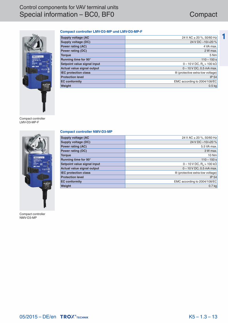
Technical data
Compact controllerLMV-D3L- MP-F
Compact controller LMV-D3L-MP-FSupply voltage (AC 24 V AC ± 20 %, 50/60 HzSupply voltage (DC) 24 V DC −10/+20 %Power rating (AC) 3.5 VA max.Power rating (DC) 2 W max.Torque 5 NmRunning time for 90° 120 – 150 sSetpoint value signal input 0 – 10 V DC, Ra > 100 kΩActual value signal output 0 – 10 V DC, 0.5 mA max.IEC protection class III (protective extra-low voltage)Protection level IP 54EC conformity EMC to 2004/108/EC, low voltage to 2006/95/ECWeight 0.5 kg
Control components for VAV terminal units Special information – BC0, BF0
05/2015 – DE/en
Compact
1
K 5 – 1.3 – 13
Compact controllerLMV-D3- MP-F
Compact controllerNMV-D3- MP
Compact controller LMV-D3-MP und LMV-D3-MP-FSupply voltage (AC 24 V AC ± 20 %, 50/60 HzSupply voltage (DC) 24 V DC −10/+20 %Power rating (AC) 4 VA max.Power rating (DC) 2 W max.Torque 5 NmRunning time for 90° 110 – 150 sSetpoint value signal input 0 – 10 V DC, Ra > 100 kΩActual value signal output 0 – 10 V DC, 0.5 mA max.IEC protection class III (protective extra-low voltage)Protection level IP 54EC conformity EMC according to 2004/108/ECWeight 0.5 kg
Compact controller NMV-D3-MPSupply voltage (AC 24 V AC ± 20 %, 50/60 HzSupply voltage (DC) 24 V DC −10/+20 %Power rating (AC) 5.5 VA max.Power rating (DC) 3 W max.Torque 10 NmRunning time for 90° 110 – 150 sSetpoint value signal input 0 – 10 V DC, Ra > 100 kΩActual value signal output 0 – 10 V DC, 0.5 mA max.IEC protection class III (protective extra-low voltage)Protection level IP 54EC conformity EMC according to 2004/108/ECWeight 0.7 kg
Control components for VAV terminal units Special information – BC0, BF0
05/2015
Compact
– DE/en
1
K 5 – 1.3 – 14
Function
Characteristics
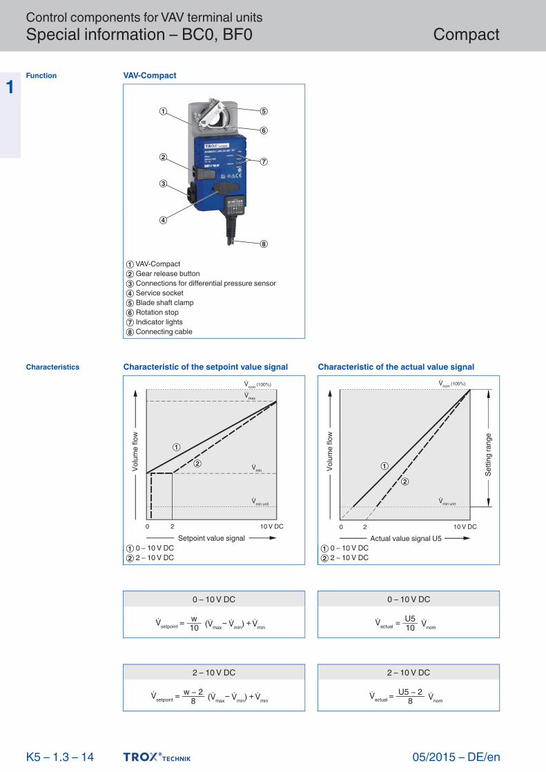
VAV-Compact
① VAV-Compact② Gear release button③ Connections for differential pressure sensor④ Service socket⑤ Blade shaft clamp⑥ Rotation stop⑦ Indicator lights⑧ Connecting cable
0 – 10 V DC
= w10setpoint max min) min
+
0 – 10 V DC
=actual nomU510
2 – 10 V DC
= w 28setpoint max min) min
+
2 – 10 V DC
=actual nomU5 2
8
Characteristic of the setpoint value signal
0 2
min
max
Setpoint value signal
min unit
nom (100%)
10 V DC
Volu
me
flow
① 0 – 10 V DC② 2 – 10 V DC
Characteristic of the actual value signal
0 2 10 V DC
min unit
nom (100%)
Actual value signal U5
Setti
ng ra
nge
Volu
me
flow
① 0 – 10 V DC② 2 – 10 V DC

Control components for VAV terminal units Special information – BC0, BF0
05/2015 – DE/en
Compact
1
K 5 – 1.3 – 15
Electrical connection
... / BC0 / ... Order code detail
Compact: LMV-D3-MP, LMV-D3-MP-F, NMV-D3-MP, LMV-D3L-MP-F
Compact: LMV-D3-MP, LMV-D3-MP-F, NMV-D3-MP, LMV-D3L-MP-F
Connecting cable core identification
Compact
1 2 3 5~ w U5/MP
– +
BK RD WT OR
1 ⊥, –: Ground, neutral2 ~, +: Supply voltage3 w: Setpoint value signal and override control5 U5/MP: Actual value signal and communication
Variable volume flow control and override control, voltage signal 0 to 10 V DC
~ y
1 2 3 5
1 2 3 5
Compact
24 VRoom temperature
controller
Slave controller Compact
S5 S4 S3 S1
Operating mode S
Operating mode E, M, F
Switch functionsS1 Room temperature controlS3 Maximum volume flow rate maxS4 Damper blade CLOSED (only with supply voltage 24 V AC)S5 Damper blade OPEN (only with supply voltage 24 V AC)All OPEN: Minimum volume flow rate min
When combining several override controls the switches must be interlocked to prevent short-circuits. Diode: e.g. 1N 4007

Control components for VAV terminal units Special information – BC0, BF0
05/2015
Compact
– DE/en
1
K 5 – 1.3 – 16
... / BC0 / ... Order code detail
Compact: LMV-D3-MP, LMV-D3-MP-F, NMV-D3-MP, LMV-D3L-MP-F
Variable volume flow control and override control, voltage signal 2 to 10 V DC
1 2 3 5
1 2 3 5
~ y
Compact
Room temperaturecontroller
Slave controller Compact
S5 S4 S3 S2 S1
Operating mode S
24 V
Operating mode E, M, F
Switch functionsS1 Room temperature controlS2 Shut-off CLOSEDS3 Maximum volume flow rate maxS4 Damper blade CLOSED (only with supply voltage 24 V AC)S5 Damper blade OPEN (only with supply voltage 24 V AC)All OPEN: Minimum volume flow rate min
When combining several override controls the switches must be interlocked to prevent short-circuits. Diode: e.g. 1N 4007

Control components for VAV terminal units Special information – BC0, BF0
05/2015 – DE/en
Compact
1
K 5 – 1.3 – 17
... / BF0 / ... Order code detail
Compact: LMV-D3-MP, LMV-D3-MP-F, NMV-D3-MP, LMV-D3L-MP-F
Dual duct terminal units Type TVM
1 2 3 5 1 2 3 5
1 2 3
~ y
TVM
24 VRoom temperature
controller
Compact controller for cold air duct Compact controller for warm air duct
Folgeregler Compact
Operating mode E, M, F
Operating mode S
Control components for VAV terminal units Special information – BL0
05/2015
Compact
– DE/en
1 Application– Electronic volume flow controller LMV-D3LON
or NMV-D3LON as Compact controller– Variable air or constant air volume flow control– The flow rate is measured using the dynamic
measurement principle– Voltage range for the actual value signal
2 – 10 V DC– Volume flow controller with LonMark certification– LonWorks interfaces for the transmission of standard network variables– Functional profiles: Node-Object #0, Damper- Actuator-Object #8110, Open-Loop-Sensor- Object #1 and Thermostat-Object #8060– The Thermostat-Object #8060 enables individual room control– A plug-in for all LNS-based network integration
tools (LNS version 3.3 and higher) is available for configuration
Construction– BL0: LMV-D3LON for TVR, TZ-Silenzio, TA- Silenzio, TVZ, TVA– BL0: NMV-D3LON for TVJ, TVT
Useful additions– AT-VAV-B: Adjustment device
Signal voltage rangeActual value signal– 2: 2 – 10 V DC
Commissioning– A trained LonWorks systems integrator must
carry out the integration into the overall system
K 5 – 1.3 – 18
Description
... / BL0
Order code detail
For detailed information on adjustment devices see chapter K5 – 1.4
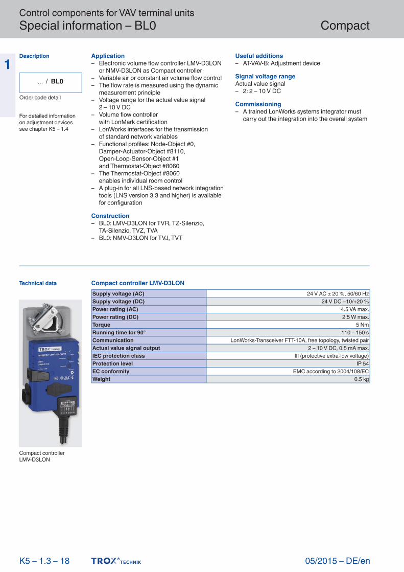
Technical data
Compact controllerLMV- D3LON
Compact controller LMV-D3LONSupply voltage (AC) 24 V AC ± 20 %, 50/60 HzSupply voltage (DC) 24 V DC −10/+20 %Power rating (AC) 4.5 VA max.Power rating (DC) 2.5 W max.Torque 5 NmRunning time for 90° 110 – 150 sCommunication LonWorks-Transceiver FTT-10A, free topology, twisted pairActual value signal output 2 – 10 V DC, 0.5 mA max.IEC protection class III (protective extra-low voltage)Protection level IP 54EC conformity EMC according to 2004/108/ECWeight 0.5 kg

Control components for VAV terminal units Special information – BL0
05/2015 – DE/en
Compact
1
K 5 – 1.3 – 19
Compact controllerNMV- D3LON
Function
Compact controller NMV-D3LONSupply voltage (AC) 24 V AC ± 20 %, 50/60 HzSupply voltage (DC) 24 V DC −10/+20 %Power rating (AC) 6 VA max.Power rating (DC) 3,5 W max.Torque 10 NmRunning time for 90° 110 – 150 sCommunication LonWorks-Transceiver FTT-10A, free topology, twisted pairActual value signal output 2 – 10 V DC, 0.5 mA max.IEC protection class III (protective extra-low voltage)Protection level IP 54EC conformity EMC according to 2004/108/ECWeight 0.7 kg
VAV-Compact
① VAV-Compact② Gear release button③ Connections for differential pressure sensor④ Service socket⑤ Blade shaft clamp⑥ Rotation stop⑦ Indicator lights and LonWorks service button⑧ Connecting cable
Control components for VAV terminal units Special information – BL0
05/2015
Compact
– DE/en
1
K 5 – 1.3 – 20
Characteristics
Electrical connection
Compact: LMV-D3LON, NMV-D3LON
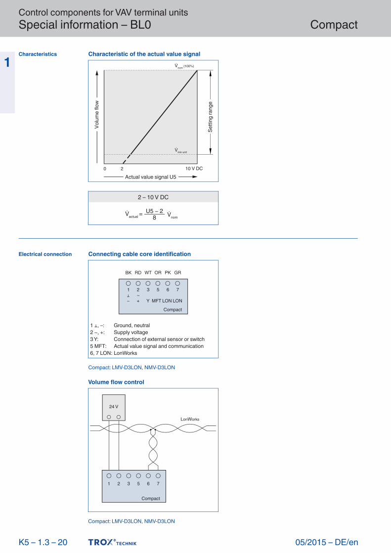
Characteristic of the actual value signal
0 2 10 V DC
min unit
nom (100%)
Actual value signal U5
Setti
ng ra
nge
Volu
me
flow
2 – 10 V DC
=actual nomU5 2
8
Connecting cable core identification
Compact
1 2 3 5 6 7
BK RD WT OR PK GR
– Y MFT LON LON+~
1 ⊥, –: Ground, neutral2 ~, +: Supply voltage3 Y: Connection of external sensor or switch5 MFT: Actual value signal and communication6, 7 LON: LonWorks
Compact: LMV-D3LON, NMV-D3LON
Volume flow control
Compact
1 2 3 5 6 7
24 V
LonWorks
Control components for VAV terminal units Special information – XB0, XG0
05/2015
Compact
– DE/en
1 Application– Electronic volume flow controller 227V-024-10
as Compact controller– Variable air or constant air volume flow control– The flow rate is measured using the dynamic
measurement principle– Voltage range for the actual and setpoint value
signals 0 – 10 V DC or 2 – 10 V DC
Construction– XB0: 227V-024-10 for TVR, TVJ, TVT, TZ- Silenzio, TA-Silenzio, TVZ, TVA– BG0: 227V-024-10 for TVM
Useful additions– AT-VAV-G: Adjustment device
Signal voltage range– 0: 0 – 10 V DC– 2: 2 – 10 V DC with shut-off function
(< 0.8 V DC)
Operating modesE: Single and M: Master– min: Minimum volume flow rate– max: Maximum volume flow rate
S: Slave operation– min: 0 %– max: Volume flow rate ratio to the master controller
F: Constant value– min: constant volume flow rate– max: 100 %
Parameters are factory set. The customer defines the required operating mode and the volume flow rates in the order code at the time of ordering.
Commissioning– On-site adjusting is not required– When installing the VAV terminal units it is important to assign each room the correct
unit based on the ordered volume flow rates– After successful installation and wiring the controller is ready for use
K 5 – 1.3 – 21
Description
... / XB0 / ...
Order code detail
... / XG0 / ...
Order code detail
For detailed information on adjustment devices see chapter K5 – 1.4
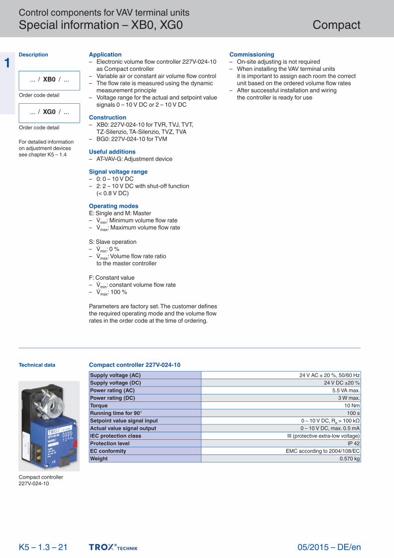
Technical data
Compact controller227V-024- 10
Compact controller 227V-024-10Supply voltage (AC) 24 V AC ± 20 %, 50/60 HzSupply voltage (DC) 24 V DC ±20 %Power rating (AC) 5.5 VA max.Power rating (DC) 3 W max.Torque 10 NmRunning time for 90° 100 sSetpoint value signal input 0 – 10 V DC, Ra > 100 kΩActual value signal output 0 – 10 V DC, max. 0.5 mAIEC protection class III (protective extra-low voltage)Protection level IP 42EC conformity EMC according to 2004/108/ECWeight 0.570 kg
Control components for VAV terminal units Special information – XB0, XG0
05/2015 – DE/en
Compact
1
K 5 – 1.3 – 22
Function
Characteristics
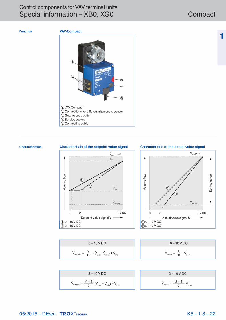
VAV-Compact
① VAV-Compact② Connections for differential pressure sensor③ Gear release button④ Service socket⑤ Connecting cable
0 – 10 V DC
= Y10setpoint max min) min
+
0 – 10 V DC
=actual nomU10
2 – 10 V DC
= Y 28setpoint max min) min
+
2 – 10 V DC
=actual nomU 2
8
Characteristic of the setpoint value signal
0 2 10 V DC
min
max
Setpoint value signal Y
min unit
nom (100%)
Volu
me
flow
① 0 – 10 V DC② 2 – 10 V DC
Characteristic of the actual value signal
0 2 10 V DC
min unit
nom (100%)
Actual value signal U
Volu
me
flow
Setti
ng ra
nge
① 0 – 10 V DC② 2 – 10 V DC

Control components for VAV terminal units Special information – XB0, XG0
05/2015
Compact
– DE/en
1
K 5 – 1.3 – 23
Electrical connection
... / XB0 / ...
Order code detail
Compact: 227V-024-10
Compact: 227V-024-10
Connecting cable core identification
1+~
–
Compact
2 3 4
Y/Z U/pp
BL BR BK GR
1 ⊥, –: Ground, neutral2 ~, +: Supply voltage3 Y/Z: Setpoint value signal and override control4 U/pp: Actual value signal and communication
Variable volume flow control and override control, voltage signal 0 to 10 V DC
~ y
1 2 3 4
1 2 3 4
Compact
24 VRoom temperature
controller
Compact
S5 S4 S3 S1
Operating mode E, M, F
Operating mode E, M, F
Switch functionsAll OPEN: Minimum volume flow rate minS1 Room temperature controlS3 Maximum volume flow rate maxS4 Damper blade CLOSED (only with supply voltage 24 V AC)S5 Damper blade OPEN (only with supply voltage 24 V AC)
When combining several override controls the switches must be interlocked to prevent short-circuits. Diode: e.g. 1N 4007

Control components for VAV terminal units Special information – XB0, XG0
05/2015 – DE/en
Compact
1
K 5 – 1.3 – 24
... / XB0 / ...
Order code detail
Compact: 227V-024-10
Variable volume flow control and override control, voltage signal 2 to 10 V DC
~ y
1 2 3 4
1 2 3 4
Compact
Operating mode E, M, F
24 V ACRoom temperature
controller
Compact
S5 S4 S3 S2 S1
Operating mode E, M, F
Switch functionsS1 Room temperature controlS2 Shut-off CLOSEDS3 Maximum volume flow rate maxS4 Damper blade CLOSED (only with supply voltage 24 V AC)S5 Damper blade OPEN (only with supply voltage 24 V AC)All OPEN: Minimum volume flow rate min
When combining several override controls the switches must be interlocked to prevent short-circuits. Diode: e.g. 1N 4007

Control components for VAV terminal units Special information – XB0, XG0
05/2015
Compact
– DE/en
1
K 5 – 1.3 – 25
... / XG0 / ...
Order code detail
Compact: 227V-024-10
Dual duct terminal units Type TVM
1 2 3 4 1 2 3 4
1 2 3
~ y24 V
Room temperaturecontroller
Compact controller for cold air duct Compact controller for warm air duct
Slave controller Compact
Operating mode S
TVM
Operating mode E, M, F

Control components for VAV terminal units Special information – LN0, LY0
05/2015 – DE/en
Compact
1 Application– Electronic volume flow controller GLB181.1E/3
as Compact controller– Variable air or constant air volume flow control– The flow rate is measured using the dynamic measurement principle– Voltage range for the actual and setpoint value signals 0 – 10 V DC– For room temperature controllers with output signal 0 – 10 V DC
Construction– LN0: GLB181.1E/3 for TVR, TVJ, TVT, TZ- Silenzio, TA-Silenzio, TVZ, TVA– LY0: GLB181.1E/3 for TVM
Useful additions– AT-VAV-S: Adjustment device
Signal voltage range– 0: 0 – 10 V DC
Operating modesE: Single and M: Master– min: Minimum volume flow rate– max: Maximum volume flow rate
S: Slave– min: 0 %– max: Volume flow rate ratio to the master controller
F: Constant value– min: constant volume flow rate– max: 100 %
Parameters are factory set. The customer defines the required operating mode and the volume flow rates in the order code at the time of ordering.
Commissioning– On-site adjusting is not required– When installing the VAV terminal units it is important to assign each room the correct
unit based on the ordered volume flow rates– After successful installation and wiring the controller is ready for use
K 5 – 1.3 – 26
Description
... / LN0 / ...
Order code detail
... / LY0 / ...
Order code detail
For detailed information on adjustment devices see chapter K5 – 1.4
Technical data
Compact controllerGLB 181.1E/3
Compact controller GLB181.1E/3Supply voltage (AC) 24 V AC ± 20 %, 50/60 HzPower rating (AC) 3 VA max.Torque 10 NmRunning time for 90° 125 – 150 sSetpoint value signal input 0 – 10 V DC, Ra > 100 kΩActual value signal output 0 – 10 V DC, max. 1 mAIEC protection class III (protective extra-low voltage)Protection level IP 54EC conformity EMC according to 2004/108/ECWeight 0.6 kg

Control components for VAV terminal units Special information – LN0, LY0
05/2015
Compact
– DE/en
1
K 5 – 1.3 – 27
Function
Characteristics
VAV-Compact
① Rotation stop② Blade shaft clamp③ Position indicator④ Service socket⑤ Gear release button⑥ Connections for differential pressure sensor⑦ Connecting cable
0 – 10 V DC
= YC10setpoint max min) min
+
0 – 10 V DC
=actual nomU10
Characteristic of the setpoint value signal
0 10 V DC
min Gerät
min
Nenn (100%)
max
Sollwertsignal YC
Volu
men
stro
m
Eins
tellb
erei
ch
① 0 – 10 V DC
Characteristic of the actual value signal
0 10 V DC
min Gerät
Nenn (100%)
Istwertsignal U
Volu
men
stro
m
① 0 – 10 V DC

Control components for VAV terminal units Special information – LN0, LY0
05/2015 – DE/en
Compact
1
K 5 – 1.3 – 28
Electrical connection
... / LN0 / ...
Order code detail
Compact: GLB181.1E/3
Compact: GLB181.1E/3
Connecting cable core identification
Compact
1 2 6 7 8 9
G G0 Y1 Y2 YC U
RD BK VI OR GR PK
1 G: Supply voltage2 G0: Ground, neutral6 Y1: Override control7 Y2: Override control8 YC: Setpoint value signal and communication9 U: Actual value signal
Variable volume flow controland override control
G G0 Y1 Y2 YC U
G G0 Y1 Y2 YC U
S1 S2
24 V ACRoom temperature
controllerG0 YG
Compact
Slave controller Compact
Switch functionsS1 Damper blade OPENS2 Damper blade CLOSEDS1 und S2 Maximum volume flow rate maxAll OPEN: Room temperature controlor minimum volume flow rate min

Control components for VAV terminal units Special information – LN0, LY0
05/2015
Compact
– DE/en
1
K 5 – 1.3 – 29
... / LN0 / ...
Order code detail
Compact: GLB181.1E/3
Dual duct terminal unit Type TVM
TVM
24 V ACRoom temperature
controllerG0 yG
G0 Y1 Y2 YC
Compact controller for cold air duct
U G G0 Y1 Y2 YC
Compact controller for warm air duct
U
G G0 Y1 Y2 YC
Slave controller Compact
U
Operating mode S
Operating mode E, M, F

05/2015 – DE/en
Variable volume flow control – VARYCONTROL Basic informationand nomenclature
1
■ Product selection ■ Principal dimensions ■ Nomenclature ■ Construction ■ Correction values for system attenuation ■ Measurements ■ Sizing and sizing example ■ Function ■ Operating modes
1.5 –
X X Grundlagen und Definitionen testregistrierung
K 5 – 1.5 – 1

Variable volume flow control – VARYCONTROL Basic information and nomenclature
05/2015 – DE/en
1 Product selection
K 5 – 1.5 – 2
TypeLVC TVR TVJ TVT TZ-Silenzio TA-Silenzio TVZ TVA TVM TVRK TVLK TVR-Ex
Type of systemSupply air ● ● ● ● ● ● ● ●Extract air ● ● ● ● ● ● ● ● ●Dual duct (supply air) ●Duct connection, fan endCircular ● ● ● ● ● ● ● ●Rectangular ● ● ● ●Volume flow rate rangeUp to [m³/h] 1080 6050 36360 36360 3025 3025 6050 6050 6050 6050 1295 6050Up to [l/s] 300 1680 10100 10100 840 840 1680 1680 1680 1680 360 1680Air qualityFiltered ● ● ● ● ● ● ● ● ● ● ●Office extract air ● ● ● ● ● ● ● ● ●Polluted ○ ○ ○ ○ ○ ● ● ○Contaminated ● ●Control functionVariable ● ● ● ● ● ● ● ● ● ● ● ●Constant ● ● ● ● ● ● ● ● ● ● ● ●Min/Max ● ● ● ● ● ● ● ● ● ● ● ●Pressure control ○ ○ ○ ○ ○ ○ ○ ○ ○Master/Slave ● ● ● ● ● ● ● ● Master ● ● ●Shut-off modeLeakage ●Low leakage ● ● ● ● ● ● ● ● ● ● ●Acoustic requirementsHigh < 40 dB(A) ○ ○ ● ● ● ● ○Low < 50 dB (A) ● ● ● ● ● ● ● ● ● ● ● ●Other functionsVolume flow rate measurement ● ● ● ● ● ● ● ● ● ● ● ●Special areasAreas with explosive atmospheres ●Labs, clean rooms, operating theatres (EASYLAB, TCU-LON II)
● ● ● ● ● ● ●
● Possible
○ Possible under certain conditions: Robust unit variant and/or specific control component (attachment) or useful additional productNot possible

Variable volume flow control – VARYCONTROL Basic information and nomenclature
05/2015 – DE/en
1 ØD [mm]VAV terminal units made of stainless steel: Outside diameter of the spigotVAV terminal units made of plastic:Inside diameter of the connecting spigot
ØD₁ [mm]Pitch circle diameter of flanges
ØD₂ [mm]Outside diameter of flanges
ØD₄ [mm]Inside diameter of the screw holes of flanges
L [mm]Length of unit including connecting spigot
L₁ [mm]Length of casing or acoustic cladding
B [mm]Duct width
B₁ [mm]Screw hole pitch of flange (horizontal)
B₂ [mm]Outside dimension of flange (width)
B₃ [mm]Width of device
H [mm]Duct height
H₁ [mm]Screw hole pitch of flange (vertical)
H₂ [mm]Outside dimension of flange (height)
H₃ [mm]Unit height
n [ ]Number of flange screw holes
T [mm]Flange thickness
m [kg]Unit weight including the minimum required attachments (e.g. Compact controller)
Acoustic datafm [Hz]Octave band centre frequency
LPA [dB(A)]A-weighted sound pressure levelof air- regenerated noise of the VAV terminal unit, system attenuation taken into account
LPA1 [dB(A)]A-weighted sound pressure levelof air- regenerated noise of the VAV terminal unit with secondary silencer, system attenuation taken into account
LPA2 [dB(A)]A-weighted sound pressure levelof case- regenerated noise of the VAV terminal unit, system attenuation taken into account
LPA3 [dB(A)]A-weighted sound pressure levelof case- regenerated noise of the VAV terminal unit with acoustic cladding, system attenuation taken into account
All sound pressure levels are based on 20 μPa.
Nomenclature
K 5 – 1.5 – 3
Principal dimensions
Definition of noise
LPA
① Air-regenerated noise② Case-radiated noise
Variable volume flow control – VARYCONTROL Basic information and nomenclature
05/2015 – DE/en
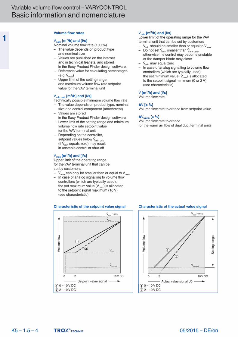
1 Volume flow ratesnom [m³/h] and [l/s]Nominal volume flow rate (100 %)– The value depends on product type and nominal size– Values are published on the internet and in technical leaflets, and stored in the Easy Product Finder design software.– Reference value for calculating percentages
(e.g. max)– Upper limit of the setting range and maximum volume flow rate setpoint value for the VAV terminal unit
min unit [m³/h] and [l/s]Technically possible minimum volume flow rate– The value depends on product type, nominal
size and control component (attachment)– Values are stored in the Easy Product Finder design software– Lower limit of the setting range and minimum
volume flow rate setpoint value for the VAV terminal unit– Depending on the controller, setpoint values below min unit (if min equals zero) may result in unstable control or shut-off
max [m³/h] and [l/s]Upper limit of the operating rangefor the VAV terminal unit that can beset by customers– max can only be smaller than or equal to nom– In case of analog signalling to volume flow
controllers (which are typically used), the set maximum value (max) is allocated to the setpoint signal maximum (10 V) (see characteristic)
min [m³/h] and [l/s]Lower limit of the operating range for the VAV terminal unit that can be set by customers– min should be smaller than or equal to max– Do not set min smaller than min unit, otherwise the control may become unstable or the damper blade may close– min may equal zero– In case of analog signalling to volume flow
controllers (which are typically used), the set minimum value (min) is allocated to the setpoint signal minimum (0 or 2 V) (see characteristic)
[m³/h] and [l/s]Volume flow rate
Δ [± %]Volume flow rate tolerance from setpoint value
Δwarm [± %]Volume flow rate tolerancefor the warm air flow of dual duct terminal units
K 5 – 1.5 – 4
Characteristic of the setpoint value signal
0 2
min
max
Setpoint value signal
min unit
nom (100%)
10 V DC
Volu
me
flow
① 0 – 10 V DC② 2 – 10 V DC
Characteristic of the actual value signal
0 2 10 V DC
min unit
nom (100%)
Actual value signal U5
Setti
ng ra
nge
Volu
me
flow
① 0 – 10 V DC② 2 – 10 V DC
Variable volume flow control – VARYCONTROL Basic information and nomenclature
05/2015 – DE/en
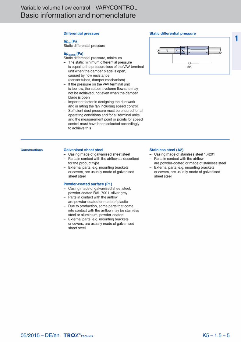
1 Differential pressureΔpst [Pa]Static differential pressure
Δpst min [Pa]Static differential pressure, minimum– The static minimum differential pressure is equal to the pressure loss of the VAV terminal
unit when the damper blade is open, caused by flow resistance (sensor tubes, damper mechanism)– If the pressure on the VAV terminal unit is too low, the setpoint volume flow rate may
not be achieved, not even when the damper blade is open
– Important factor in designing the ductwork and in rating the fan including speed control– Sufficient duct pressure must be ensured for all
operating conditions and for all terminal units, and the measurement point or points for speed control must have been selected accordingly
to achieve this
Galvanised sheet steel– Casing made of galvanised sheet steel– Parts in contact with the airflow as described
for the product type– External parts, e.g. mounting brackets or covers, are usually made of galvanised
sheet steel
Powder-coated surface (P1)– Casing made of galvanised sheet steel,
powder-coated RAL 7001, silver grey– Parts in contact with the airflow are powder- coated or made of plastic– Due to production, some parts that come into contact with the airflow may be stainless
steel or aluminium, powder-coated– External parts, e.g. mounting brackets or covers, are usually made of galvanised
sheet steel
Stainless steel (A2)– Casing made of stainless steel 1.4201– Parts in contact with the airflow are powder- coated or made of stainless steel– External parts, e.g. mounting brackets or covers, are usually made of galvanised
sheet steel
K 5 – 1.5 – 5
Constructions
Static differential pressure
st

Variable volume flow control – VARYCONTROL Basic information and nomenclature
05/2015 – DE/en
1
K 5 – 1.5 – 6
The quick sizing tables show the sound pressure levels that can be expected in a room both for the air-regenerated noise and for the case- radiated noise. The sound pressure level in a room results from the sound power level of the products – for a given volume flow rate and differential pressure –and the attenuationand insulation on site. Generally accepted attenuation and insulation values have been taken into account.The distribution of air across the ductwork, changes of direction, end reflection, and room attenuation all affectthe sound pressure level of the air-regenerated noise.Ceiling insulation and room attenuation influence the sound pressure level of the case-radiated noise.
Correction valuesfor acoustic quick sizing
The correction valuesfor the distributionin the ducting are based on the number of diffusers assigned to any oneair terminal unit. If there is just one diffuser (assumption: 140 l/s or 500 m³/h), no correction is necessary.
One change of direction, e.g. at the horizontal connection of the diffuser plenum box, has been taken into consideration for the system attenuation values. Vertical connection of the plenum box does not resultin a system attenuation. Additional bends resultin lower sound pressure levels.
System attenuation per octave to VDI 2081 for the calculation of the air-regenerated noise
Centre fre quency [Hz] 63 125 250 500 1000 2000 4000 8000
ΔL dB
Change of direction 0 0 1 2 3 3 3 3
Mündungsrefle xion 10 5 2 0 0 0 0 0
Room attenuation 5 5 5 5 5 5 5 5
The calculation is based on the end reflection for nominal size 250
Octave correction for the distribution in the ducting,used to calculate the air-regenerated noise in [m³/h] 500 1000 1500 2000 2500 3000 4000 5000
[l/s] 140 280 420 550 700 840 1100 1400[dB] 0 3 5 6 7 8 9 10
Reducing the sound pressure level of the air-regenerated noise
① VAV terminal unit② Distribution in the ducting③ Change of direction
④ End reflection⑤ Ceiling insulation
Octave correction for the calculation of case-radiated noise
Centre fre quency [Hz] 63 125 250 500 1000 2000 4000 8000
ΔL dB
Ceiling insulation 4 4 4 4 4 4 4 4
Room attenuation 5 5 5 5 5 5 5 5

Variable volume flow control – VARYCONTROL Basic information and nomenclature
05/2015 – DE/en
1
K 5 – 1.5 – 7
Measurements
The acoustic datafor the air-regenerated noise and case- radiated noise are determined according to EN ISO 5135.All measurementsare carried out in a reverberation chamber to EN ISO 3741.
The sound pressure levels for air-regenerated noise LPA given by us result from measurementsin a reverberation chamber. The sound pressure LP is measured for the entire frequency range.The evaluation of the measurements, including system attenuation and A-weighting, results in the sound pressure level LPA.
Measuring the air-regenerated noise
st
LP
① Reverberation chamber② VAV terminal unit③ Microphone
④ Fan⑤ Sound attenuator
The sound pressure levels for case-radiated noise LPA2 given by us result from measurementsin a reverberation chamber. The sound pressure LP is measured for the entire frequency range. The evaluation of the measurements, including system attenuation and A-weighting,results in the sound pressure level LPA2.
Measuring the case-radiated noise
st
LP
① Reverberation chamber② VAV terminal unit③ Microphone
④ Fan⑤ Sound attenuator

Variable volume flow control – VARYCONTROL Basic information and nomenclature
05/2015 – DE/en
1 This catalogue provides convenient quick sizing tables for VAV terminal units. The sound pressure levels for air-regenerated noise and for case-radiated noise are provided for all nominal sizes. In addition, generally accepted attenuationand insulation values have been taken into account. Sizing data for other volume flowrates and differential pressures can bedetermined quickly and precisely usingthe Easy Product Finder design programme.
Given datamax = 280 l/s (1010 m3/h)Δpst = 150 PaRequired sound pressurelevel in the room 30 dB(A)
Quick sizingTVZ-D/200Air-regenerated noise LPA = 23 dB(A)Case-radiated noise LPA3 = 24 dB(A)
Sound pressure level in the room = 27 dB(A)(logarithmic addition since the terminal unit is installed in the suspended ceiling of the room)
K 5 – 1.5 – 8
Sizing withthe help of this catalogue
Sizing example
Easy Product Finder
The Easy Product Finder allows you to size products using your project-specific data.
You will findthe Easy Product Finder on our website.
Variable volume flow control – VARYCONTROL Basic information and nomenclature
05/2015 – DE/en
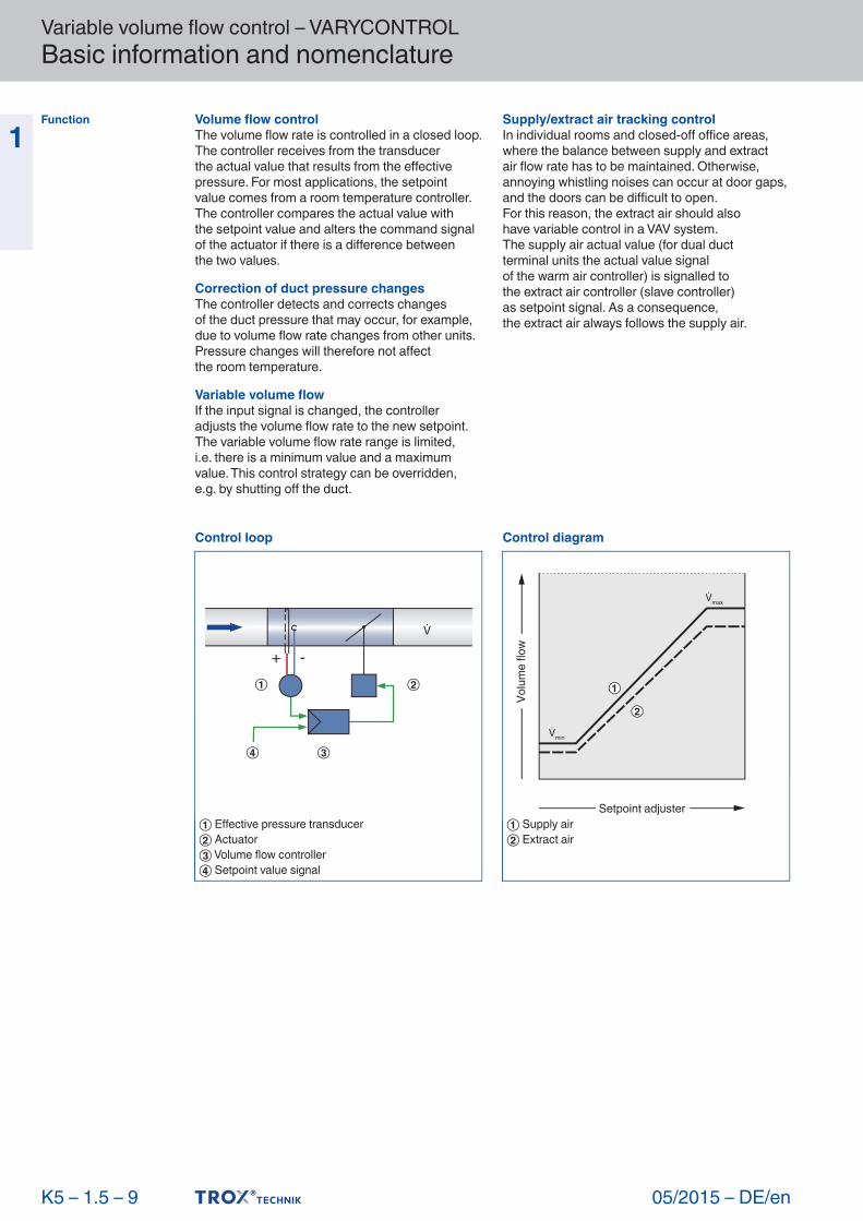
1 Volume flow controlThe volume flow rate is controlled in a closed loop. The controller receives from the transducer the actual value that results from the effective pressure. For most applications, the setpointvalue comes from a room temperature controller. The controller compares the actual value withthe setpoint value and alters the command signal of the actuator if there is a difference betweenthe two values.
Correction of duct pressure changesThe controller detects and corrects changesof the duct pressure that may occur, for example, due to volume flow rate changes from other units. Pressure changes will therefore not affectthe room temperature.
Variable volume flowIf the input signal is changed, the controller adjusts the volume flow rate to the new setpoint. The variable volume flow rate range is limited,i.e. there is a minimum value and a maximum value. This control strategy can be overridden,e.g. by shutting off the duct.
Supply/extract air tracking controlIn individual rooms and closed-off office areas, where the balance between supply and extractair flow rate has to be maintained. Otherwise, annoying whistling noises can occur at door gaps, and the doors can be difficult to open.For this reason, the extract air should alsohave variable control in a VAV system.The supply air actual value (for dual ductterminal units the actual value signalof the warm air controller) is signalled tothe extract air controller (slave controller)as setpoint signal. As a consequence,the extract air always follows the supply air.
K 5 – 1.5 – 9
Function
Control loop
+ -
① Effective pressure transducer② Actuator③ Volume flow controller④ Setpoint value signal
Control diagram
min
max
Setpoint adjuster
Volu
me
flow
① Supply air② Extract air

Operating modes Single operation
+ -
t
Slave operation (master)
+ -
t
+ -
Variable volume flow control – VARYCONTROL Basic information and nomenclature
05/2015 – DE/en
1
K 5 – 1.5 – 10
Constant value
+ -
Slave operation (slave)
+ -
t
+ -