vav terminal unit - eindec · pdf filevariable air volume terminal unit vav - 1. kyodo ......
TRANSCRIPT
VAV TERMINAL UNIT
KYODO-ALLIED TECHNOLOGY PTE LTD
MODE INTRODU
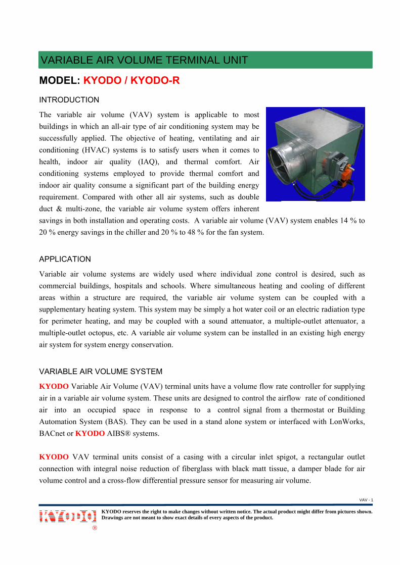
The variabuildings successfulconditionihealth, inconditioniindoor airrequiremeduct & msavings in20 % ener APPLICA
Variable commerciareas withsupplemenfor perimemultiple-oair system VARIABL
KYODO air in a vaair into AutomatioBACnet o KYODO connectionvolume co
VAV &
KDr
®
L: KYO
UCTION
able air voin which anlly applied.ing (HVACndoor air ing systemr quality coent. Comparmulti-zone, tn both instalrgy savings
ATION
air volumeal buildinghin a strucntary heatineter heating
outlet octopm for system
LE AIR VO
Variable Aariable air v
an occupon System (or KYODO
VAV termn with integontrol and a
& CAV T
KYODO reservesrawings are not
ODO / KY
olume (VAn all-air typ. The objec
C) systems quality (
s employeonsume a sired with otthe variablellation and oin the chille
e systems ags, hospitalscture are r
ng system. Tg, and mayus, etc. A v
m energy con
OLUME SY
Air Volume olume syste
pied space (BAS). TheAIBS® sys
minal units gral noise r
a cross-flow
TERMINA
the right to makmeant to show e
YODO-R
AV) systempe of air coctive of heis to satisfyIAQ), andd to provignificant pther all aire air volumoperating coer and 20 %
are widely s and schoorequired, thThis systemy be couplevariable air nservation.
STEM
(VAV) termem. These u
in respoey can be ustems.
consist of reduction o differential
AL UNIT
ke changes withexact details of e
R
m is appliconditioning eating, ventfy users whd thermal ide thermaart of the b
r systems, sme system osts. A var
% to 48 % fo
used wherols. Where he variable
m may be simed with a s
volume sy
minal units hunits are deonse to a used in a sta
a casing wof fiberglassl pressure se
T
out written noticevery aspects of t
cable to msystem maytilating and
hen it comecomfort.
l comfort building enesuch as douoffers inhe
riable air voor the fan sy
re individusimultaneo
e air volummply a hot wsound attenstem can be
have a volusigned to co control s
and alone s
with a circus with blackensor for m
ce. The actual prthe product.
most y be
d air es to
Air and
ergy uble
erent olume (VAVystem.
ual zone coous heatingme system water coil o
nuator, a mue installed i
ume flow raontrol the aignal from system or in
ular inlet spk matt tissu
measuring air
roduct might dif
V) system e
ontrol is deg and cooli
can be cor an electricultiple-outlein an existi
ate controlleairflow rate
a thermostnterfaced w
pigot, a recue, a damper volume.
ffer from picture
enables 14 %
esired, suchng of diffeoupled witc radiation tet attenuatoing high ene
er for supplye of conditiotat or Build
with LonWo
ctangular ouer blade for
es shown.
% to
h as erent th a type or, a ergy
ying oned ding orks,
utlet r air
VARIABLE AIR VOLUME TERMINAL UNIT
VAV - 1
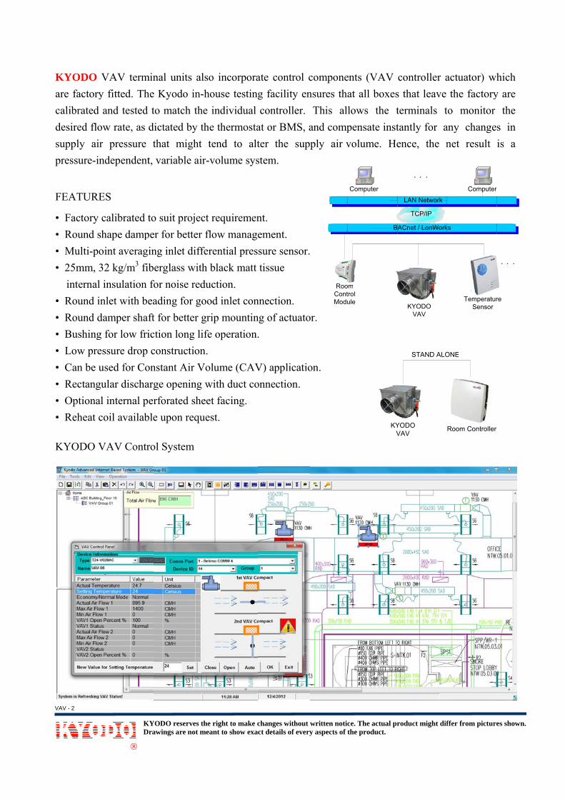
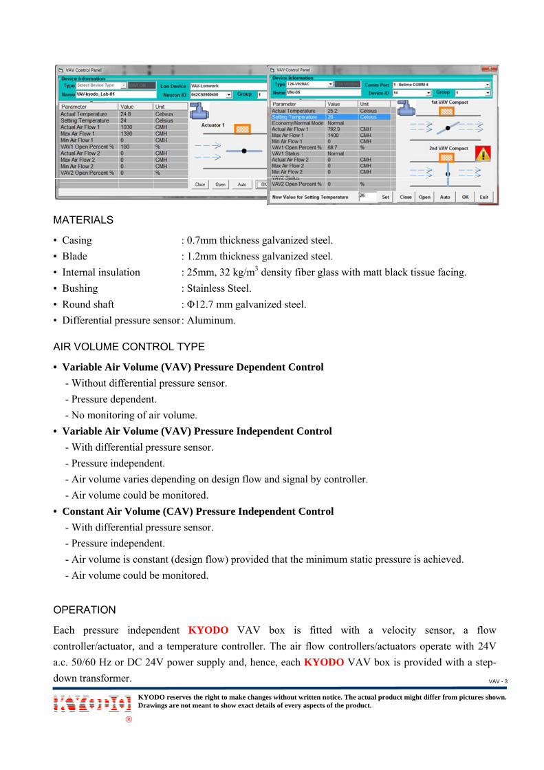
KYODO are factorycalibrated desired flosupply airpressure-in
FEATURE
• Factory • Round s• Multi-po• 25mm, 3
internal• Round i• Round d• Bushing• Low pre• Can be u• Rectang• Optiona• Reheat c KYODO V
KDr
®
VAV termy fitted. Thand tested
ow rate, as dr pressure ndependent
ES
calibrated tshape dampoint averagi32 kg/m3 fibl insulation inlet with bedamper shafg for low friessure drop used for Co
gular dischaal internal pecoil availab
VAV Contr
KYODO reservesrawings are not
minal units ahe Kyodo in
to match thdictated by that might, variable a
to suit projeper for bettering inlet difberglass wifor noise reeading for gft for better iction long lconstructio
onstant Air Varge openingerforated sh
ble upon req
rol System
the right to makmeant to show e
also incorpon-house testhe individuthe thermot tend to
air-volume s
ect requiremr flow manafferential prth black ma
eduction. good inlet cogrip mount
life operatioon. Volume (CAg with duct heet facing.quest.
ke changes withexact details of e
orate controting facility al controllestat or BMSalter the s
system.
ment. agement. ressure sensatt tissue
onnection.ting of actuaon.
AV) applicaconnection
out written noticevery aspects of t
ol componeensures tha
er. This alS, and compsupply air v
or.
ator.
ation. .
RooContModu
ce. The actual prthe product.
KYV
ents (VAV at all boxeslows the tpensate instvolume. He
Computer
omtrolule
B
roduct might dif
YODO VAV
STAND ALO
controller as that leave terminals ttantly for aence, the n
TCP/IP
LAN Network
ACnet / LonWork
KYODO VAV
ffer from picture
Room Controller
ONE
actuator) whthe factory
to monitor any changenet result
TemperaturSensor
ks
Computer
es shown.
hich y are
the s in is a
re
r
VAV - 2
MATERIA
• Casing • Blade • Internal • Bushing• Round s• Differen
AIR VOL
• Variabl- Witho- Pressu- No m
• Variabl- With - Pressu- Air vo- Air vo
• Constan- With - Pressu- Air vo- Air vo
OPERAT
Each precontroller/a.c. 50/60 down tran
KDr
®
ALS
insulation g shaft ntial pressur
UME CON
le Air Voluout differenture dependeonitoring ofle Air Voludifferential ure indepenolume varieolume couldnt Air Voludifferential ure indepenolume is conolume could
TION
essure inde/actuator, an Hz or DC
nsformer.
KYODO reservesrawings are not
: 0 : 1 : 2 : S : Φ
re sensor : A
NTROL TY
ume (VAV) tial pressureent. f air volume
ume (VAV) pressure se
ndent. es dependingd be monitoume (CAV)pressure se
ndent. nstant (desid be monito
ependent Knd a tempe24V power
the right to makmeant to show e
0.7mm thick.2mm thick
25mm, 32 kgStainless SteΦ12.7 mm gAluminum.
PE
Pressure De sensor.
e. Pressure I
ensor.
g on designored. ) Pressure Iensor.
ign flow) prored.
KYODO Verature contr supply an
ke changes withexact details of e
kness galvankness galvang/m3 densityeel. galvanized s
Dependent
Independen
n flow and si
Independen
rovided that
VAV box troller. The d, hence, ea
out written noticevery aspects of t
nized steel.nized steel.y fiber glas
steel.
Control
nt Control
ignal by con
nt Control
t the minimu
is fittedair flow co
ach KYOD
ce. The actual prthe product.
s with matt
ntroller.
um static pr
with a vontrollers/ac
DO VAV bo
roduct might dif
black tissu
ressure is ac
velocity sectuators opox is provid
ffer from picture
e facing.
chieved.
ensor, a ferate with 2
ded with a s
es shown.
flow 24V step-
VAV - 3
The flow room tempbox and wa feedbacmonitors tthe flow csignal to tof air thrimmediateKYODO system/KYcommunic OPERAT
1. Air fduct signathe dupstr
2. Whensignafrom corre
3. The pthe spwill bthe thminim
INSTALL
All KYODsteel wire
KDr
®
controller/aperature co
will continuock signal tothe room temcontroller/acthe actuatorrough until ely respond
VAV boxYODO AIcation hardw
TING CONT
flow is heldpressure flu
al directly todamper actuream duct prn the tempeal to the flow
the air flowect amount oproportionapace tempebe maintainhermostat smum setting
LATION
DO VAV/Cor threaded
KYODO reservesrawings are not
actuator recontroller. Thously monito the flowmperature, ctuator. Ther that contin
the room to any chan
xes can bIBS® systware.
TROL SEQ
d constant iuctuation, ito the flow cator to closressure. erature conw controllerw sensor, aof air to maial band of terature of 0ned at a pre-setpoint, theg.
CAV boxesd rods.
the right to makmeant to show e
ceives two ihe airflow stor the quan
w controllercompares ite flow contrnuously mod
setpoint tenge in roome fully intem/Fan op
QUENCE
in accordant will immecontroller/ace or open th
ntroller sensr/actuator, w
and regulateintain spacethe tempera.5K above -selected me air flow t
s are finish
ke changes withexact details of e
inputs, one sensor is inntity of air pr/actuator. Tt to the setproller/actuadulates the emperature
m temperaturntegrated inptimizers
nce with thediately be sctuator. Thehe damper t
ses a changwhich will ces the air voe temperatuature controthe thermoaximum setthrough the
ed with sta
out written noticevery aspects of t
from the astalled with
passing throuThe room
point temperator comparVAV box dis obtaine
re and fluctnto a DDCsystem wh
ermostat demsensed by the flow contrto compens
ge in space compare theolume contr
ure within thller is fixedstat setpointting and at VAV box
andard hang
ce. The actual prthe product.
airflow senshin the airstugh the boxtemperatur
rature and ses the two damper to ad. The flowtuation in duC controllehen equipp
mand. Shouhe air flow sroller/actua
sate for the
temperature reset signrol damper
he setpoint od at 0.5K ont, the air fl
the space twill be ma
ger brackets
roduct might dif
sor and the tream at thex and continre controllesends the reqinputs and
allow the rew controlleuct pressureer/LonWorkped with
uld there besensor whic
ator will tranincrease or
re, it will tnal with the
accordinglyof temperatuof setpoint tlow throughtemperatureaintained at
s for install
ffer from picture
other frome inlet of Vnuously prover continuoquired signasends a con
equired quaner/actuator e. ks or BACthe additi
e any upstrch transmitsnsmit signaldecrease in
transmit a rsignal recey to supplyure controlltemperatureh the VAV e of 0.5K bet a pre-sele
lation by ei
es shown.
m the VAV vide usly al to ntrol ntity will
Cnet onal
ream s the ls to
n the
reset ived
y the ler. e. At
box elow ected
ither
VAV - 4

1. Units
the un2. Turbu
flow 3. A mi
is rec
4. Close
5. The d6. All c7. Outle8. Seali
speci9. It is
bandseale
KDr
®
s are to be snits be instaulent flow avariation. A
inimum of tcommended
e coupling t
diameter of ontrol encloet duct or atng of ducifications. recommend. Rigid ducd in accorda
KYODO reservesrawings are not
supported inalled prior tapproachingAvoid abrupthree duct d
d.
the terminal
f the inlet duosures requittenuators arct work to
ded that flect should beance with th
the right to makmeant to show e
n a horizonto installatiog the terminpt transitiondiameters o
l unit inlet t
uct must be ire adequatere field mou
preclude
exible ductwe slipped ovhe job speci
ke changes withexact details of e
ntal and leveon of the ceinal will creans or duct tuf straight du
to the side o
equal to thee clearance unted with sair leaks
work connever the inletifications.
out written noticevery aspects of t
el position. iling tile griate additionurns at the inuct upstream
of the main d
e listed inletto allow forslip and drivshould be
ected to thet, secured i
ce. The actual prthe product.
For convenid system. al noise, pr
nlet of the um of inlet d
WARNINGHAZARDOUS VOLTAGE.Contact may causeelectric shock or burn.Turn off and lock outsystem before servicing.
duct is NOT
WARNINGHAZARDOUS VOLTAGE.Contact may causeelectric shock or burn.Turn off and lock outsystem before servicing.
t collar diamr field adjusve cleats pro
done in
e inlet be sn place wit
roduct might dif
nience, it is
essure dropunit. differential p
T recommen
meter of thestments andovided by oaccordance
ecured usinth sheet me
ffer from picture
s suggested
p and greate
pressure sen
nded.
e terminal und service. others. with the
ng compresetal screws,
es shown.
that
er air
nsor
nit.
job
ssion and
VAV - 5

DIMENS Model: KY
Model: KY
KDr
®
ION AND T
YODO
YODO-R
KYODO reservesrawings are not
TECHNICA
the right to makmeant to show e
AL DATA
ke changes withexact details of e
out written noticevery aspects of t
ce. The actual prthe product.
roduct might dif
WARNINGHAZARDOUS VOLTAGE.Contact may causeelectric shock or burn.Turn off and lock outsystem before servicing.
WARNINGHAZARDOUS VOLTAGE.Contact may causeelectric shock or burn.Turn off and lock outsystem before servicing.
WARNINGHAZARDOUS VOLTAGE.Contact may causeelectric shock or burn.Turn off and lock outsystem before servicing.
ffer from picture
es shown.
VAV - 6

KYODO reserves the right to make changes without written notice. The actual product might differ from pictures shown. Drawings are not meant to show exact details of every aspects of the product.
®
Dimension (mm) Model D W H L C Weight (kg)
KYODO-15 Φ150 300 250 300 100 8 KYODO-20 Φ200 320 300 330 100 10 KYODO-25 Φ250 360 320 350 100 11 KYODO-30 Φ300 460 400 380 100 13 KYODO-35 Φ350 520 500 400 100 17 KYODO-40 Φ400 620 500 450 100 20
Model D A L Weight (kg) KYODO-R-15 Φ150 90 400 6 KYODO-R-20 Φ200 115 400 7 KYODO-R-25 Φ250 140 500 8 KYODO-R-30 Φ300 165 500 9 KYODO-R-35 Φ350 190 600 11 KYODO-R-40 Φ400 215 600 13
• Internal insulation 25mm, 32 kg/m3 density coated to prevent air erosion (Model: KYODO). • Galvanized steel housing. • Rectangular discharge opening (Model: KYODO). • Turbulent flow approaching the terminal will create additional noise, pressure drop and greater air flow variation. It is
therefore recommended for optimum performance there should be a minimum of 3 duct diameters of straight inlet duct, the same size as the inlet, between the inlet and any transition, take off or fitting.
Air Volume Ranges
Air Volume Range Model Size (mm) Min. CMH Max. CMH
KYODO-15 Φ150 105 800 KYODO-20 Φ200 185 1400 KYODO-25 Φ250 305 2400 KYODO-30 Φ300 455 3500 KYODO-35 Φ350 680 5500 KYODO-40 Φ400 965 7000
Air Volume Range Model Size (mm) Min. CMH Max. CMH
KYODO-R-15 Φ150 105 800 KYODO-R-20 Φ200 185 1400 KYODO-R-25 Φ250 305 2400 KYODO-R-30 Φ300 455 3500 KYODO-R-35 Φ350 680 5500 KYODO-R-40 Φ400 965 7000
Model Neck Velocity (m/s) 2.0 3.0 4.0 5.0 6.0 8.0 10.0 12.0 ---- Air Volume (CMH) 130 190 250 320 380 510 640 760 800 KYODO-(R)-15 S.P. (Pa) 6 9 12 16 20 32 50 59 61 Air Volume (CMH) 230 340 450 570 680 900 1130 1350 1400KYODO-(R)-20 S.P. (Pa) 5 9 11 16 19 30 48 57 60 Air Volume (CMH) 350 530 710 880 1060 1410 1770 2120 2400KYODO-(R)-25 S.P. (Pa) 5 8 10 15 18 28 47 55 63 Air Volume (CMH) 510 760 1020 1270 1530 2040 2540 3050 3500KYODO-(R)-30
S.P. (Pa) 5 7 11 15 18 26 45 55 64 Air Volume (CMH) 690 1040 1390 1730 2080 2770 3460 4150 5500KYODO-(R)-35
S.P. (Pa) 4 7 10 14 17 25 42 52 71 Air Volume (CMH) 900 1360 1810 2260 2710 3620 4520 5420 7000KYODO-(R)-40
S.P. (Pa) 5 8 12 16 18 28 41 50 70 * S.P. - Static Pressure drops are in Pascals. All data has been generated in which damper blade is fully open. VAV - 7

Discharg Model: K
Size (mm)
Φ 150
Φ 200
Φ 250
Φ 300
Φ 350
Φ 400
Note: 1. A
22. A3. ∆
KDr
®
ge Sound
KYODO
Air Volum(CMH)
300 400 500 600 700 800 400 600 800
1000 1200 1400 600 900
1200 1600 2000 2400 1000 1500 2000 2500 3000 3500 1500 2500 3500 4200 4800 5500 2000 3000 4000 5000 6000 7000
All sound data:1994, ANSI
All Sound pow∆Ps - is inlet s
KYODO reservesrawings are not
Power (d
me )
@
125 254 56 59 60 62 64 54 60 62 64 66 67 54 58 60 66 68 70 60 64 66 69 70 71 62 66 69 70 71 71 60 62 66 68 70 72
a based upo/ ASHRAE S
wer level, dBstatic pressu
the right to makmeant to show e
dB)
125 Pa ∆POctave Ba
250 50051 46 53 48 56 53 58 54 60 56 62 57 50 46 54 50 56 52 60 54 62 56 64 58 51 45 55 49 57 55 60 58 63 59 65 62 56 49 59 56 62 59 64 61 66 63 67 64 58 55 60 58 64 61 65 63 66 64 67 64 53 52 55 54 59 58 62 61 64 63 67 66
n tests condStandard 130
B re: 10-12 waure minus dis
ke changes withexact details of e
SoundPs (0.5" w.gand (Hz) 1k 2k 43 40 46 43 48 45 51 47 53 48 54 49 42 41 47 44 49 46 52 48 54 49 55 50 43 42 47 46 53 47 56 50 57 51 59 53 47 44 53 51 55 53 57 54 58 55 59 56 52 50 53 51 57 53 58 54 58 55 59 56 50 49 51 50 55 53 56 55 58 56 59 58
ucted in acco0-2008 (Methtts.
scharge static
out written noticevery aspects of t
d Power Levg.)
4k 12534 5836 6039 6240 6442 6545 6635 5839 6442 6644 6845 6948 7036 6040 6342 6645 7047 7250 7340 6543 6845 7048 7150 7252 7441 6844 7048 7150 7251 7354 7440 6442 6646 7048 7251 7354 75
ordance withhods of Test
c pressure.
ce. The actual prthe product.
vel (dB) @ 250Pa ∆
Octave5 250 500
56 5258 5461 5762 6065 6167 6354 5360 5463 5665 5968 6070 6258 5361 5763 5968 6369 6472 6662 5764 6067 6369 6571 6772 6863 5965 6169 6369 6571 6772 6858 5660 5764 6367 6568 6671 69
h ISO 3741:1ting Air Term
roduct might dif
∆Ps (1.0" we Band (Hz)0 1k 2k
2 47 464 50 487 54 50 56 521 57 533 59 543 46 444 49 486 52 509 55 520 56 532 58 543 48 477 55 529 57 543 60 564 61 586 63 587 53 520 57 553 59 575 61 597 63 608 64 69 56 541 58 553 60 585 62 607 63 68 64 626 55 537 56 543 60 585 61 596 62 609 64 62
1999, ISO 37minal Units).
ffer from picture
w.g.) ) k 4k 6 41 8 43 1 46 2 48 3 50 4 52 4 42 8 45 0 48 2 50 3 51 4 52 7 42 2 46 4 48 6 52 8 53 8 54 2 47 5 50 7 52 9 54 0 56 1 58 4 49 5 52 8 54 0 56 1 58 2 59 3 48 4 50 8 53 9 56 0 59 2 60
743-
es shown.
VAV - 8

Discharg
Model: K
Size (mm)
Φ 150
Φ 200
Φ 250
Φ 300
Φ 350
Φ 400
Note: 1. A
22. A3. ∆
KDr
®
ge Sound
KYODO
Air Volum(CMH)
300 400 500 600 700 800 400 600 800
1000 1200 1400 600 900
1200 1600 2000 2400 1000 1500 2000 2500 3000 3500 1500 2500 3500 4200 4800 5500 2000 3000 4000 5000 6000 7000
All sound data:1994, ANSI
All Sound pow∆Ps - is inlet s
KYODO reservesrawings are not
Power (d
me )
@
125 262 65 67 68 70 71 60 66 68 69 70 72 64 68 70 72 73 74 68 71 73 74 75 76 70 72 73 74 76 77 67 69 72 74 76 78
a based upo/ ASHRAE S
wer level, dBstatic pressu
the right to makmeant to show e
dB)
500 Pa ∆POctave Ba
250 50061 58 64 60 67 63 69 65 71 66 73 68 62 56 65 58 67 60 70 63 73 64 75 66 68 66 70 68 73 70 74 70 75 68 76 69 65 60 70 64 72 66 74 68 76 70 77 72 68 63 71 65 72 68 74 70 75 71 77 72 64 60 66 63 69 65 71 68 72 70 75 72
n tests condStandard 130
B re: 10-12 waure minus dis
ke changes withexact details of e
SoundPs (2.0" w.gand (Hz) 1k 2k 52 51 54 53 56 56 60 58 61 59 63 60 50 47 53 52 54 55 56 57 59 58 60 59 51 50 60 57 65 60 66 62 67 63 67 64 56 56 61 60 64 62 66 64 67 65 68 66 60 59 62 61 65 62 66 64 67 65 68 66 59 58 61 59 64 62 66 64 67 65 68 67
ucted in acco0-2008 (Methtts.
scharge static
out written noticevery aspects of t
d Power Levg.)
4k 12548 6550 6653 6954 7055 7257 7446 6550 6952 7054 7156 7458 7548 6755 7056 7258 7459 7660 7854 7256 7460 7661 7762 7864 7955 7357 7460 7662 7763 7864 7954 7056 7259 7561 7762 7865 81
ordance withhods of Test
c pressure.
ce. The actual prthe product.
vel (dB) @ 750Pa ∆
Octave5 250 500
64 6067 6370 6672 6874 6975 7164 5868 6071 6373 6676 6778 6871 6972 7074 6975 7078 7178 7269 6472 6676 6978 7279 7480 7572 6574 6777 7178 7278 7480 7564 6166 6270 6873 7075 7177 74
h ISO 3741:1ting Air Term
roduct might dif
∆Ps (3.0" we Band (Hz)0 1k 2k
0 54 553 56 576 59 608 62 69 64 621 65 638 52 530 53 563 56 576 59 587 61 608 62 69 62 540 68 69 69 630 69 651 71 672 70 674 58 596 64 639 66 652 68 674 70 685 70 695 63 627 65 641 67 662 69 674 69 685 70 691 62 602 64 628 67 640 68 651 69 674 71 70
1999, ISO 37minal Units).
ffer from picture
w.g.) ) k 4k 5 52 7 54 0 57 1 58 2 59 3 61 3 50 6 54 7 56 8 58 0 59 1 60 4 52 1 58 3 60 5 62 7 63 7 64 9 58 3 60 5 64 7 65 8 66 9 67 2 58 4 61 6 63 7 65 8 66 9 68 0 58 2 60 4 62 5 64 7 65 0 68
743-
es shown.
VAV - 9

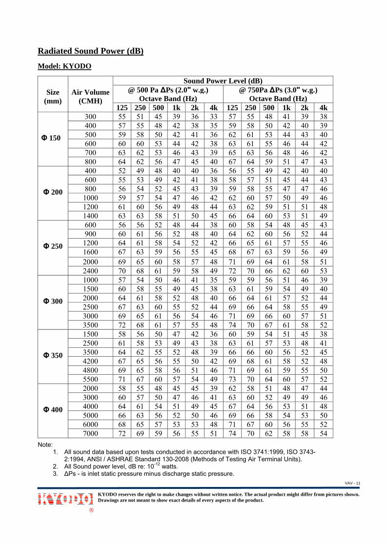
Radiated Model: K
Size (mm)
Φ 150
Φ 200
Φ 250
Φ 300
Φ 350
Φ 400
Note: 1. A
22. A3. ∆
KDr
®
d Sound P
KYODO
Air Volum(CMH)
300 400 500 600 700 800 400 600 800
1000 1200 1400 600 900
1200 1600 2000 2400 1000 1500 2000 2500 3000 3500 1500 2500 3500 4200 4800 5500 2000 3000 4000 5000 6000 7000
All sound data:1994, ANSI
All Sound pow∆Ps - is inlet s
KYODO reservesrawings are not
Power (dB
me )
@
125 252 53 54 56 57 58 45 48 50 51 53 57 46 49 56 60 62 63 48 53 56 60 61 63 49 53 56 59 61 63 50 52 56 58 61 63
a based upo/ ASHRAE S
wer level, dBstatic pressu
the right to makmeant to show e
B)
125 Pa ∆POctave Ba
250 50044 35 47 39 49 40 51 42 53 44 55 45 40 35 43 38 46 41 48 44 51 45 54 48 45 40 46 42 48 45 50 47 52 48 54 50 43 39 47 43 50 46 53 49 55 51 56 52 46 39 49 42 54 46 55 48 56 48 57 50 45 39 46 41 51 44 53 47 56 50 59 54
n tests condStandard 130
B re: 10-12 waure minus dis
ke changes withexact details of e
SoundPs (0.5" w.gand (Hz) 1k 2k 29 27 32 30 34 32 37 34 39 35 41 36 30 26 33 30 36 34 39 36 42 40 43 40 36 32 40 36 42 38 45 43 47 45 48 46 32 30 37 33 41 36 41 39 43 41 45 43 35 30 43 37 45 40 46 41 47 42 47 44 37 35 39 37 43 41 44 42 46 44 48 46
ucted in acco0-2008 (Methtts.
scharge static
out written noticevery aspects of t
d Power Levg.)
4k 12522 5424 5627 5828 5930 6031 6122 4824 5028 5430 5632 5934 6123 5225 5727 6130 6332 6634 6727 5328 5830 6032 6335 6535 6729 5432 5836 6038 6439 6540 6728 5430 5633 6034 6236 6539 68
ordance withhods of Test
c pressure.
ce. The actual prthe product.
vel (dB) @ 250Pa ∆
Octave5 250 500
48 4051 4254 4556 4758 4960 5044 4147 4349 4652 4956 5058 5246 4354 4855 5258 5459 5460 5550 4652 5055 5258 5360 5661 5752 4456 4757 4960 5361 5462 5549 4350 4556 4859 5262 5366 55
h ISO 3741:1ting Air Term
roduct might dif
∆Ps (1.0" we Band (Hz)0 1k 2k
0 32 32 36 335 39 367 41 389 42 390 44 401 34 323 37 346 40 409 43 420 45 442 47 463 41 388 45 432 48 454 51 484 53 505 54 56 38 340 44 382 47 433 49 456 49 487 51 494 40 387 44 429 46 433 51 464 51 485 52 493 38 365 43 48 47 462 48 473 50 495 52 5
1999, ISO 37minal Units).
ffer from picture
w.g.) ) k 4k 1 27 3 29 6 32 8 33 9 34 0 36 2 27 4 29 0 35 2 36 4 38 6 40 8 31 3 32 5 34 8 38 0 40 1 44 4 29 8 31 3 34 5 38 8 40 9 43 8 35 2 38 3 40 6 42 8 43 9 44 6 34 1 35 6 38 7 40 9 42 1 45
743-
es shown.
VAV - 10
Radiated Model: K
Size (mm)
Φ 150
Φ 200
Φ 250
Φ 300
Φ 350
Φ 400
Note: 1. A
22. A3. ∆
KDr
®
d Sound P
KYODO
Air Volum(CMH)
300 400 500 600 700 800 400 600 800
1000 1200 1400 600 900
1200 1600 2000 2400 1000 1500 2000 2500 3000 3500 1500 2500 3500 4200 4800 5500 2000 3000 4000 5000 6000 7000
All sound data:1994, ANSI
All Sound pow∆Ps - is inlet s
KYODO reservesrawings are not
Power (dB
me )
@
125 255 57 59 60 63 64 52 55 56 59 61 63 56 60 64 67 69 70 57 60 64 67 69 72 58 61 64 67 69 71 58 60 64 66 68 72
a based upo/ ASHRAE S
wer level, dBstatic pressu
the right to makmeant to show e
B)
500 Pa ∆POctave Ba
250 50051 45 55 48 58 50 60 53 62 53 62 56 49 48 53 49 54 52 57 54 60 56 63 58 56 52 61 56 61 58 63 59 65 60 68 61 54 50 58 55 61 58 63 60 65 61 68 61 56 50 58 53 62 55 65 56 65 58 67 60 55 48 57 50 61 54 63 56 65 57 69 59
n tests condStandard 130
B re: 10-12 waure minus dis
ke changes withexact details of e
SoundPs (2.0" w.gand (Hz) 1k 2k 39 36 42 38 42 41 44 42 46 43 47 45 40 40 42 41 45 43 47 46 49 48 51 50 48 44 52 48 54 52 56 55 58 57 59 58 46 41 49 45 52 48 55 52 56 54 57 55 47 42 49 43 52 48 55 50 56 51 57 54 45 45 47 46 51 49 52 50 53 53 56 55
ucted in acco0-2008 (Methtts.
scharge static
out written noticevery aspects of t
d Power Levg.)
4k 12533 5735 5936 6238 6339 6540 6736 5638 5839 5942 6244 6345 6638 6040 6442 6645 6848 7149 7235 5938 6340 6644 6946 7148 7436 6038 6339 6642 6946 7149 7339 6241 6345 6746 6948 7151 74
ordance withhods of Test
c pressure.
ce. The actual prthe product.
vel (dB) @ 750Pa ∆
Octave5 250 500
55 4858 5061 5361 5563 5664 5955 4957 5158 5560 5762 5964 6058 5462 6065 6167 6369 6470 6659 5661 5964 6166 6469 6670 6759 5461 5766 6068 6169 6170 6458 5160 5264 5666 5867 6070 62
h ISO 3741:1ting Air Term
roduct might dif
∆Ps (3.0" we Band (Hz)0 1k 2k
8 41 390 42 403 44 435 46 446 48 469 51 479 42 401 45 445 47 477 50 499 51 50 53 54 48 450 56 521 57 553 59 564 61 586 62 606 51 469 54 491 57 524 58 556 60 577 61 584 51 457 53 480 56 521 58 521 59 554 60 571 48 472 49 496 53 58 54 530 56 552 58 58
1999, ISO 37minal Units).
ffer from picture
w.g.) ) k 4k 9 38 0 39 3 40 4 42 6 42 7 43 0 40 4 43 7 46 9 46 1 48 1 49 5 43 2 44 5 46 6 49 8 51 0 53 6 39 9 40 2 44 5 49 7 51 8 52 5 38 8 41 2 45 2 48 5 50 7 52 7 44 9 46 1 48 3 50 5 52 8 54
743-
es shown.
VAV - 11
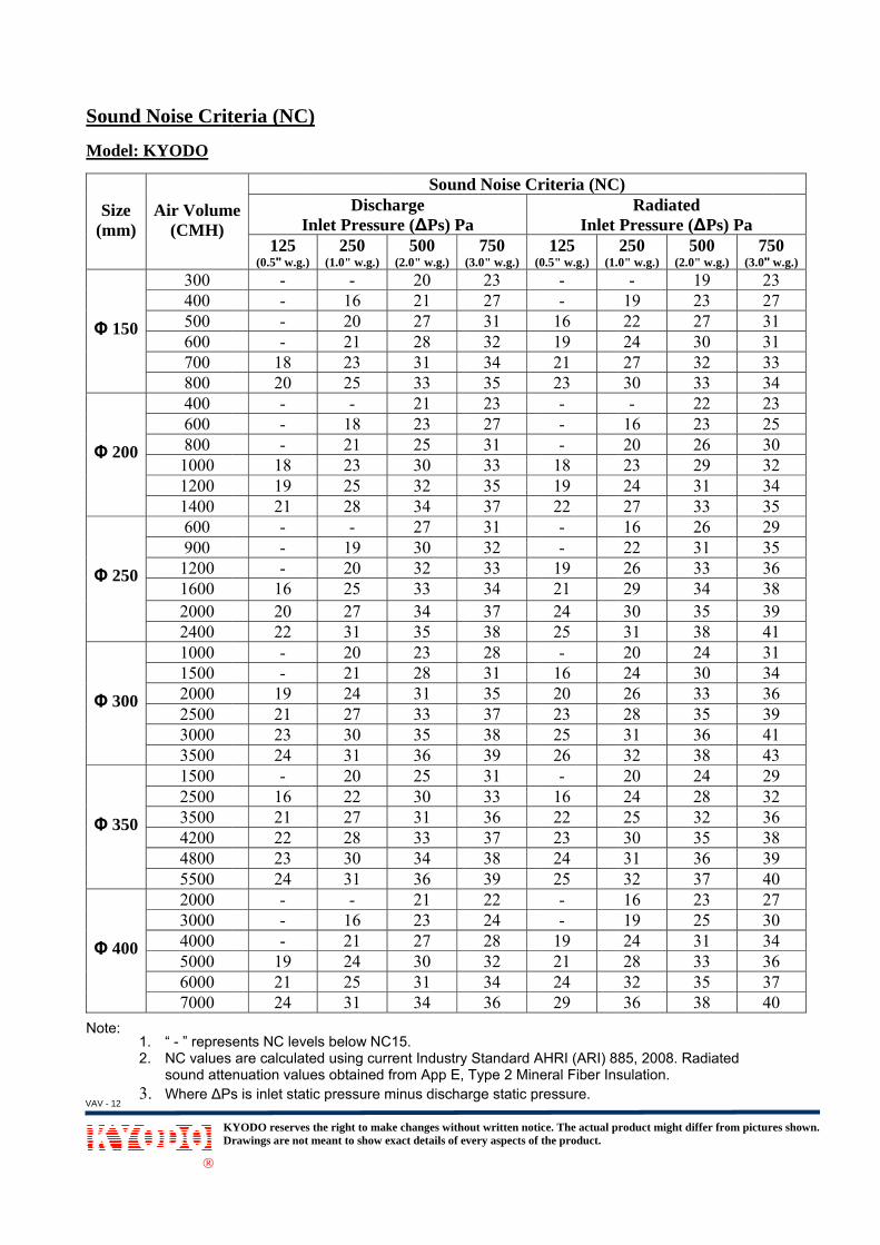
Sound N Model: K
Size (mm)
A
Φ 150
Φ 200
Φ 250
Φ 300
Φ 350
Φ 400
Note: 1. “ 2. N
so3. W
KDr
®
Noise Crit
KYODO
Air Volum(CMH)
300 400 500 600 700 800 400 600 800
1000 1200 1400 600 900
1200 1600 2000 2400 1000 1500 2000 2500 3000 3500 1500 2500 3500 4200 4800 5500 2000 3000 4000 5000 6000 7000
- ” representNC values areound attenua
Where ∆Ps is
KYODO reservesrawings are not
teria (NC)
me In
125 (0.5" w.g.)
- - - -
18 20 - - -
18 19 21 - - -
16 20 22 - -
19 21 23 24 -
16 21 22 23 24 - - -
19 21 24
ts NC levels e calculated ation values s inlet static p
the right to makmeant to show e
)
Dischnlet Pressu
250
(1.0" w.g.)-
16 20 21 23 25 -
18 21 23 25 28 -
19 20 25 27 31 20 21 24 27 30 31 20 22 27 28 30 31 -
16 21 24 25 31
below NC15using currenobtained fro
pressure min
ke changes withexact details of e
Sounharge ure (∆Ps) P
500 (2.0" w.g.)
20 21 27 28 31 33 21 23 25 30 32 34 27 30 32 33 34 35 23 28 31 33 35 36 25 30 31 33 34 36 21 23 27 30 31 34
5. nt Industry Stm App E, Ty
nus discharge
out written noticevery aspects of t
nd Noise Cr
Pa 750
(3.0" w.g.) (023 27 31 32 34 35 23 27 31 33 35 37 31 32 33 34 37 38 28 31 35 37 38 39 31 33 36 37 38 39 22 24 28 32 34 36
tandard AHRype 2 Minerae static press
ce. The actual prthe product.
riteria (NC
Inlet 125
0.5" w.g.) (1.0- -
16 19 21 23 - - -
18 19 22 - -
19 21 24 25 -
16 20 23 25 26 -
16 22 23 24 25 - -
19 21 24 29
RI (ARI) 885,l Fiber Insulasure.
roduct might dif
) Radiated
Pressure (∆250 0" w.g.)
5(2.0"
- 119 222 224 327 330 3- 2
16 220 223 224 327 316 222 326 329 330 331 320 224 326 328 331 332 320 224 225 330 331 332 316 219 224 328 332 336 3
2008. Radiaation.
ffer from picture
d ∆Ps) Pa
500 " w.g.)
75(3.0" w
19 2323 2727 3130 3132 3333 3422 2323 2526 3029 3231 3433 3526 2931 3533 3634 3835 3938 4124 3130 3433 3635 3936 4138 4324 2928 3232 3635 3836 3937 4023 2725 3031 3433 3635 3738 40
ated
es shown.
50 w.g.) 3 7 1 1 3 4 3 5 0 2 4 5 9 5 6 8 9 1 1 4 6 9 1 3 9 2 6 8 9 0 7 0 4 6 7 0
VAV - 12

Discharg Model: K
Size (mm)
Φ 150
Φ 200
Φ 250
Φ 300
Φ 350
Φ 400
Note: 1. A
22. A3. ∆
KDr
®
ge Sound
KYODO-R
Air Volum(CMH)
300 400 500 600 700 800 400 600 800
1000 1200 1400 600 900
1200 1600 2000 2400 1000 1500 2000 2500 3000 3500 1500 2500 3500 4200 4800 5500 2000 3000 4000 5000 6000 7000
All sound data:1994, ANSI
All Sound pow∆Ps - is inlet s
KYODO reservesrawings are not
Power (d
me )
@
125 254 57 61 63 65 69 53 61 64 65 68 70 54 59 64 68 71 72 59 65 67 71 73 74 61 66 70 72 73 74 59 62 68 71 73 74
a based upo/ ASHRAE S
wer level, dBstatic pressu
the right to makmeant to show e
dB)
125 Pa ∆POctave Ba
250 50050 47 53 49 57 53 59 54 61 58 64 60 51 48 55 50 58 52 62 53 64 58 67 60 51 46 55 50 58 54 63 57 64 61 68 65 56 52 61 58 63 59 65 62 68 65 70 65 58 55 62 58 65 61 68 65 70 65 71 68 53 51 56 54 63 60 67 65 70 65 72 70
n tests condStandard 130
B re: 10-12 waure minus dis
ke changes withexact details of e
SoundPs (0.5" w.gand (Hz) 1k 2k 44 40 46 42 48 46 52 46 55 48 60 52 42 42 47 45 50 47 51 50 54 51 55 52 43 42 47 45 53 48 55 52 58 54 62 57 49 44 54 51 56 53 58 54 61 55 65 58 51 50 54 51 57 53 60 54 61 57 63 57 48 48 53 52 55 54 60 54 64 60 65 63
ucted in acco0-2008 (Methtts.
scharge static
out written noticevery aspects of t
d Power Levg.)
4k 12536 5738 6140 6442 6544 6847 7138 5840 6544 6846 6948 7049 7338 5941 6244 6748 7250 7353 7542 6544 6846 7050 7352 7454 7545 6647 7050 7251 7453 7554 7743 6445 6747 7150 7453 7556 77
ordance withhods of Test
c pressure.
ce. The actual prthe product.
vel (dB) @ 250Pa ∆
Octave5 250 500
54 5158 5461 5861 6164 6268 6555 5259 5564 5865 5968 6271 6554 5359 5764 5968 6370 6472 6961 5864 6266 6369 6671 6772 6862 5968 6369 6470 6873 7073 7359 5561 5766 6469 6570 6871 69
h ISO 3741:1ting Air Term
roduct might dif
∆Ps (1.0" we Band (Hz)0 1k 2k
1 48 464 51 508 54 51 56 522 59 555 62 572 48 455 53 498 55 509 57 542 59 565 62 583 47 467 55 529 56 553 61 564 63 589 66 628 52 52 57 563 58 576 61 597 63 608 67 639 56 543 58 554 61 588 66 630 66 653 68 685 53 507 56 544 60 605 62 608 66 639 66 65
1999, ISO 37minal Units).
ffer from picture
w.g.) ) k 4k 6 42 0 44 1 47 2 49 5 53 7 53 5 44 9 46 0 49 4 52 6 52 8 54 6 42 2 47 5 50 6 53 8 54 2 56 1 48 6 50 7 53 9 56 0 58 3 59 4 50 5 52 8 55 3 58 5 60 8 62 0 48 4 50 0 55 0 60 3 60 5 62
743-
es shown.
VAV - 13

Discharg
Model: K
Size (mm)
Φ 150
Φ 200
Φ 250
Φ 300
Φ 350
Φ 400
Note: 1. A
22. A3. ∆
KDr
®
ge Sound
KYODO-R
Air Volum(CMH)
300 400 500 600 700 800 400 600 800
1000 1200 1400 600 900
1200 1600 2000 2400 1000 1500 2000 2500 3000 3500 1500 2500 3500 4200 4800 5500 2000 3000 4000 5000 6000 7000
All sound data:1994, ANSI
All Sound pow∆Ps - is inlet s
KYODO reservesrawings are not
Power (d
me )
@
125 261 66 68 71 72 74 60 66 69 71 73 74 66 69 72 73 75 75 67 72 74 75 77 79 69 73 75 77 79 82 69 71 74 75 78 81
a based upo/ ASHRAE S
wer level, dBstatic pressu
the right to makmeant to show e
dB)
500 Pa ∆POctave Ba
250 50059 57 64 60 67 64 68 65 71 67 73 70 58 56 63 58 66 62 69 65 72 68 75 69 66 64 68 67 70 68 72 70 75 72 76 73 65 59 69 62 72 66 74 70 76 71 76 74 68 64 71 66 73 68 73 70 76 71 78 75 65 61 67 64 70 66 72 70 75 70 78 76
n tests condStandard 130
B re: 10-12 waure minus dis
ke changes withexact details of e
SoundPs (2.0" w.gand (Hz) 1k 2k 53 52 56 54 59 56 61 58 61 59 66 62 52 49 52 52 56 55 58 58 60 58 62 59 55 53 60 56 65 61 67 63 69 65 70 65 58 56 60 58 64 63 65 64 67 66 70 69 62 58 62 62 66 62 68 65 68 67 72 68 59 57 62 59 64 63 68 66 70 68 72 70
ucted in acco0-2008 (Methtts.
scharge static
out written noticevery aspects of t
d Power Levg.)
4k 12546 6448 6850 7053 7355 7556 7746 6650 6953 7255 7457 7659 7850 6855 7258 7560 7661 7763 7955 7156 7460 7762 7864 8066 8254 7358 7561 7863 8165 8468 8555 7356 7460 7863 7966 8369 84
ordance withhods of Test
c pressure.
ce. The actual prthe product.
vel (dB) @ 750Pa ∆
Octave5 250 500
62 6067 6469 6672 6874 7074 7164 5766 6070 6473 6876 7077 7267 6570 6673 6975 7176 7477 7467 6471 6776 7078 7279 7579 7870 6575 6977 7379 7580 7682 7967 6369 6674 6976 7379 7582 78
h ISO 3741:1ting Air Term
roduct might dif
∆Ps (3.0" we Band (Hz)0 1k 2k
0 56 544 58 576 60 608 63 60 64 621 68 667 54 520 56 554 58 578 62 600 64 622 67 635 63 586 63 69 68 641 69 654 71 654 72 674 60 597 64 630 68 662 70 675 71 688 72 725 64 629 66 643 67 675 70 696 72 729 76 753 62 606 64 639 67 653 70 675 72 708 78 77
1999, ISO 37minal Units).
ffer from picture
w.g.) ) k 4k 4 51 7 53 0 54 1 56 2 58 6 61 2 50 5 55 7 56 0 59 2 60 3 62 8 54 1 59 4 61 5 62 5 65 7 66 9 58 3 61 6 65 7 66 8 68 2 69 2 58 4 62 7 65 9 67 2 69 5 72 0 58 3 61 5 64 7 67 0 68 7 72
743-
es shown.
VAV - 14

Radiated Model: K
Size (mm)
Φ 150
Φ 200
Φ 250
Φ 300
Φ 350
Φ 400
Note: 1. A
22. A3. ∆
KDr
®
d Sound P
KYODO-R
Air Volum(CMH)
300 400 500 600 700 800 400 600 800
1000 1200 1400 600 900
1200 1600 2000 2400 1000 1500 2000 2500 3000 3500 1500 2500 3500 4200 4800 5500 2000 3000 4000 5000 6000 7000
All sound data:1994, ANSI
All Sound pow∆Ps - is inlet s
KYODO reservesrawings are not
Power (dB
me )
@
125 253 54 55 56 58 59 45 48 51 52 55 58 47 49 55 61 63 65 49 55 58 61 63 64 51 53 57 58 63 64 50 52 57 60 63 65
a based upo/ ASHRAE S
wer level, dBstatic pressu
the right to makmeant to show e
B)
125 Pa ∆POctave Ba
250 50045 37 48 39 51 41 53 45 55 49 56 51 42 36 45 39 46 43 50 47 53 48 56 51 45 40 47 44 49 46 53 47 55 50 58 55 46 41 49 45 52 48 55 49 58 53 61 57 47 39 50 45 54 47 56 50 59 54 62 55 46 38 48 42 52 46 55 50 59 54 62 55
n tests condStandard 130
B re: 10-12 waure minus dis
ke changes withexact details of e
SoundPs (0.5" w.gand (Hz) 1k 2k 29 28 32 30 36 33 40 38 44 40 48 44 32 27 36 34 40 37 41 38 46 44 49 47 38 36 41 39 43 42 46 43 48 46 52 49 38 35 39 37 43 38 45 42 49 45 53 49 36 35 42 38 45 42 48 44 52 48 53 50 37 35 41 38 45 42 48 46 50 47 54 49
ucted in acco0-2008 (Methtts.
scharge static
out written noticevery aspects of t
d Power Levg.)
4k 12524 5528 5731 5934 6036 6142 6224 4827 5131 5435 5840 5946 6324 5228 5731 6234 6441 6847 6928 5531 5834 6237 6542 6647 6931 5534 5839 6142 6444 6648 6828 5532 5835 6140 6442 6749 69
ordance withhods of Test
c pressure.
ce. The actual prthe product.
vel (dB) @ 250Pa ∆
Octave5 250 500
50 4153 4455 4557 4858 5360 5845 4148 4550 4655 5357 5558 5748 4554 4757 5260 5463 5863 6150 4753 5057 5359 5562 5965 6353 4655 4858 4961 5461 5765 5948 4453 4758 5261 5665 5767 62
h ISO 3741:1ting Air Term
roduct might dif
∆Ps (1.0" we Band (Hz)0 1k 2k
1 33 34 37 345 40 378 43 403 47 438 52 491 36 325 40 376 43 403 49 465 52 497 54 55 42 397 46 422 49 464 52 488 56 51 58 557 42 390 46 403 47 425 49 469 54 503 58 556 40 398 44 439 48 464 52 497 55 529 57 534 41 377 44 422 48 486 52 507 55 542 58 57
1999, ISO 37minal Units).
ffer from picture
w.g.) ) k 4k 1 28 4 32 7 35 0 38 3 41 9 46 2 28 7 33 0 38 6 40 9 44 1 49 9 31 2 34 6 37 8 41 1 46 5 50 9 30 0 33 2 37 6 42 0 46 5 51 9 37 3 40 6 43 9 45 2 48 3 51 7 35 2 38 8 42 0 46 4 49 7 54
743-
es shown.
VAV - 15

Radiated Model: K
Size (mm)
Φ 150
Φ 200
Φ 250
Φ 300
Φ 350
Φ 400
Note: 1. A
22. A3. ∆
KDr
®
d Sound P
KYODO-R
Air Volum(CMH)
300 400 500 600 700 800 400 600 800
1000 1200 1400 600 900
1200 1600 2000 2400 1000 1500 2000 2500 3000 3500 1500 2500 3500 4200 4800 5500 2000 3000 4000 5000 6000 7000
All sound data:1994, ANSI
All Sound pow∆Ps - is inlet s
KYODO reservesrawings are not
Power (dB
me )
@
125 256 58 60 62 64 65 53 56 58 60 63 65 58 61 64 68 70 72 58 60 65 68 71 73 59 62 65 68 70 72 58 61 64 67 70 73
a based upo/ ASHRAE S
wer level, dBstatic pressu
the right to makmeant to show e
B)
500 Pa ∆POctave Ba
250 50052 46 55 48 58 51 60 53 62 55 63 59 50 48 54 52 56 53 58 56 60 58 64 62 56 54 61 57 63 60 65 62 67 65 68 66 55 52 59 56 62 59 64 62 66 64 70 66 57 52 59 54 63 57 66 60 68 65 68 66 54 46 58 52 62 54 64 58 68 60 69 67
n tests condStandard 130
B re: 10-12 waure minus dis
ke changes withexact details of e
SoundPs (2.0" w.gand (Hz) 1k 2k 40 37 44 40 45 43 46 44 47 46 50 48 42 40 44 42 46 44 50 48 52 49 57 55 50 46 53 48 57 54 58 57 60 60 63 62 46 42 49 48 54 48 58 55 61 58 64 61 48 42 52 46 55 50 56 52 59 56 63 59 44 44 48 46 51 49 54 52 57 56 64 60
ucted in acco0-2008 (Methtts.
scharge static
out written noticevery aspects of t
d Power Levg.)
4k 12534 5836 6038 6340 6444 6646 6936 5740 6041 6145 6347 6651 6938 6142 6546 6849 7152 7355 7536 6239 6543 6948 7252 7556 7735 6339 6542 6946 7351 7555 7838 6242 6546 6850 7253 7558 76
ordance withhods of Test
c pressure.
ce. The actual prthe product.
vel (dB) @ 750Pa ∆
Octave5 250 500
55 4958 5261 5462 5665 6066 6355 5158 5459 5861 5863 6165 6359 5864 6168 6468 6569 6772 6858 5762 6064 6266 6571 6875 7060 5564 5966 6270 6673 6974 7159 5161 5565 5869 6172 6774 72
h ISO 3741:1ting Air Term
roduct might dif
∆Ps (3.0" we Band (Hz)0 1k 2k
9 42 402 45 434 46 446 49 450 53 493 57 531 44 424 46 448 50 488 53 51 55 543 59 578 54 481 58 544 61 575 63 577 66 628 66 647 52 480 55 502 58 525 63 588 66 620 69 655 51 489 57 532 60 566 64 599 66 641 69 661 47 465 51 498 54 51 58 557 63 602 70 68
1999, ISO 37minal Units).
ffer from picture
w.g.) ) k 4k 0 38 3 40 4 42 5 44 9 47 3 50 2 40 4 44 8 47 1 50 4 52 7 56 8 44 4 46 7 50 7 53 2 56 4 60 8 40 0 42 2 48 8 54 2 57 5 62 8 39 3 43 6 49 9 53 4 56 6 62 6 44 9 47 1 50 5 54 0 57 8 63
743-
es shown.
VAV - 16
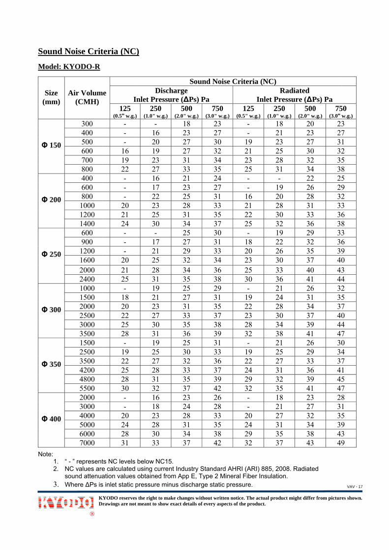
Sound N Model: K
Size (mm)
A
Φ 150
Φ 200
Φ 250
Φ 300
Φ 350
Φ 400
Note: 1. “ 2. N
so3. W
KDr
®
Noise Crit
KYODO-R
Air Volum(CMH)
300 400 500 600 700 800 400 600 800
1000 1200 1400 600 900
1200 1600 2000 2400 1000 1500 2000 2500 3000 3500 1500 2500 3500 4200 4800 5500 2000 3000 4000 5000 6000 7000
- ” representNC values areound attenua
Where ∆Ps is
KYODO reservesrawings are not
teria (NC)
me In
125 (0.5" w.g.)
- - -
16 19 22 - - -
20 21 24 - - -
20 21 25 -
18 20 22 25 28 -
19 22 25 28 30 - -
20 24 28 31
ts NC levels e calculated ation values s inlet static p
the right to makmeant to show e
)
Dischnlet Pressu
250
(1.0" w.g.)-
16 20 19 23 27 16 17 22 23 25 30 -
17 21 25 28 31 19 21 23 27 30 31 19 25 27 28 31 32 16 18 23 28 30 33
below NC15using currenobtained fro
pressure min
ke changes withexact details of e
Sounharge ure (∆Ps) P
500 (2.0" w.g.)
18 23 27 27 31 33 21 23 25 28 31 34 25 27 29 32 34 35 25 27 31 33 35 36 25 30 32 33 35 37 23 24 28 31 34 37
5. nt Industry Stm App E, Ty
nus discharge
out written noticevery aspects of t
nd Noise Cr
Pa 750
(3.0" w.g.) (023 27 30 32 34 35 24 27 31 33 35 37 30 31 33 34 36 38 29 31 35 37 38 39 31 33 36 37 39 42 26 28 33 35 38 42
tandard AHRype 2 Minerae static press
ce. The actual prthe product.
riteria (NC
Inlet 125
0.5" w.g.) (1.0- -
19 21 23 25 - -
16 21 22 25 -
18 20 23 25 30 -
19 22 23 28 32 -
19 22 24 29 32 - -
20 24 29 32
RI (ARI) 885,l Fiber Insulasure.
roduct might dif
) Radiated
Pressure (∆250 0" w.g.)
5(2.0"
18 221 223 225 328 331 3- 2
19 220 228 330 332 319 222 326 330 333 436 421 224 328 330 334 338 421 225 227 331 332 335 418 221 227 331 335 337 4
2008. Radiaation.
ffer from picture
d ∆Ps) Pa
500 " w.g.)
75(3.0" w
20 2323 2727 3130 3232 3534 3822 2526 2928 3231 3333 3636 3829 3332 3635 3937 4040 4341 4426 3231 3534 3737 4039 4441 4726 3029 3433 3736 4139 4541 4723 2827 3132 3534 3938 4343 49
ated
es shown.
50 w.g.) 3 7 1 2 5 8 5 9 2 3 6 8 3 6 9 0 3 4 2 5 7 0 4 7 0 4 7 1 5 7 8 1 5 9 3 9
VAV - 17

KYODO-ALLIED TECHNOLOGY PTE LTD
Sales Office and Factory:
Tel: (65)6265-1311 Fax: (65)6265-8100Website: www.kyodo.com.sg
KYODO-ALLIED (MALAYSIA) SDN. BHD.
K.L. Office:Tel: (03)7958-7641 / 7958-7724
Fax: (03)7958-7614
J.B. Office:Lot 854 Jalan Sengkang,
81000 Kulai, Johor, MalaysiaTel: (07)6637-467-9 Fax: (07)6637-290
KYODO-ALLIED (THAILAND) CO., LTD.
Bangkok Office:1475 Soi Ladprow 94 (Phanjamit), Ladprow Road,
Wongthonglang, Bangkok 10310, ThailandTel: (02)559-2790 / 559-2791
Fax: (02)559-2792
KYODO-ALLIED TRADING (SHANGHAI) CO., LTD.
Room 2509 Zhong Cheng Building,No. 818 Dong Fang Road,
Shanghai Pudong 200122 ChinaTel: (86)21-6360-7138 Fax: (86)21-6360-7137
KA
(DP
)_M
AR
’13
8 Pandan Crescent #01-06, Singapore 128464