installation of vav-compact retrofit with zdms-..vav-compact retrofit zdms-.. installation...
TRANSCRIPT

www.belimo.eu M4-VAV-Compact Retrofit ZDMS-.. • en • v1.0 • 04.2012 • Subject to changes 1 / 8
Installation of VAV-Compact Retrofit with ZDMS-..
LMVAX-D3-MP NMVAX-D3-MP ZDMS-..VAV-Compact Retrofit for utilisation of existing VAV devices made by various manufacturers.• for various air velocities• for round and rectangular units
General Information
Application The VAV-Compact Retrofit solution was designed for the retooling of existing VAV-/CAV units. The replacement of VAV control devices from a wide variety of manufacturers, including pneumatic solutions, is exceptionally simple.The ZTH-GEN service tool or the Belimo PC-Tool (MFT-P) is used for the adaptation of the VAV-Compact Retrofit to the existing VAV unit and the air velocity.
To be noted If the existing pick-up device is to continue to be used, then the unit and the pick-up device must be checked and cleaned if necessary, because otherwise the control function/accuracy cannot be ensured.
Installation instruction This installation instruction describes the application of the VAV-Compact Retrofit ..-D3-MP. For the more detailed description of the VAV controller, we refer to the separate product information VAV-Compact (NMV-D3-MP); to the product information ZDMS-.. for the pick-up device and to the product information of the ZTH-GEN for the adjustment tool and to the operating instruction PC-Tool – VAV-Compact D2 and D3 Module, see www.belimo.eu.Belimo Automation AG can at any time implement changes and improvements without prior notification. For the current edition of the operating instruction, see www.belimo.eu.
Safety notes
!• The device must not be used outside the specified field of application, especially not in
aircraft or in any other airborne means of transport.• It may only be installed by suitably trained personnel. Any legal regulations or regulations
issued by authorities must be observed during installation.• The device may only be opened at the manufacturer's site. It does not contain any parts that
can be replaced or repaired by the user.• The cable must not be removed from the device.• When calculating the torque required, the specifications supplied by the damper
manufacturers (cross-section, construction, place of installation), and the ventilation conditions must be observed.
• The device contains electrical and electronic components and is not allowed to be disposed of as household refuse. All locally valid regulations and requirements must be observed.
Selection
Actual status VAV unit The replacement controller required should be defined on the basis of the existing VAV unit.The setting data should be arrived at as well.
Mechanical
• Torque• Spindle form / dimensions• Unit dimensions (for the selection of the pick-up device)• Angle of rotation• Position of end stops
Settings / control
• nom, max, min (possibly mid)• Direction of rotation• Mode (0 ... 10V / 2 ... 10V)• Calibration value / ∆p @ nom• Override control (no / yes (how))
VAV-Compact Retrofit ZDMS-.. Installation
2 / 8 M4-VAV-Compact Retrofit ZDMS-.. • en • v1.0 • 04.2012 • Subject to changes www.belimo.eu
Selection (continued)
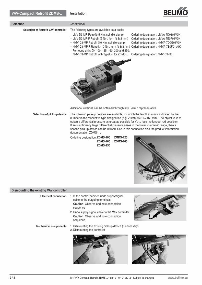
Selection of Retrofit VAV controller The following types are available as a basis:
– LMV-D3-MP Retrofit (5 Nm, spindle clamp) Ordering designation: LMVA-7D0101V0K– LMV-D3-MP-F Retrofit (5 Nm, form fit 8x8 mm) Ordering designation: LMVA-7E0F01V0K– NMV-D3-MP Retrofit (10 Nm, spindle clamp) Ordering designation: NMVA-7D0G01V0K– NMV-D3-MP-F Retrofit (10 Nm, form fit 8x8 mm) Ordering designation: NMVA-7E0F01V0K– For round units DN 100, 125, 160, 200 and 250:
NMV-D3-MP Retrofit with TypeList for ZDMS-.. Ordering designation: NMV-D3-RE
Additional versions can be obtained through any Belimo representative.
Selection of pick-up device The following pick-up devices are available, for which the length in mm is indicated by the number in the respective type designation (e.g. ZDMS-160: l = 160 mm). The objective is to obtain a differential pressure as great as possible for nom (use the longest rod possible). If an insufficiently large differential pressure arises in the lower volumetric range, then a second pick-up device can be utilised. See in this connection also the product information documentation ZDMS-.. .
Ordering designation:ZDMS-100 ZMDS-125ZDMS-160 ZDMS-200ZDMS-250
Dismounting the existing VAV controller
Electrical connection 1. In the control cabinet, undo supply/signal cable to the outgoing terminalsCaution: Observe and note connection sequence
2. Undo supply/signal cable to the VAV controllerCaution: Observe and note connection sequence
Mechanical components 1. Dismounting the existing pick-up device (if necessary)2. Dismounting the controller

VAV-Compact Retrofit ZDMS-.. Installation
www.belimo.eu M4-VAV-Compact Retrofit ZDMS-.. • en • v1.0 • 04.2012 • Subject to changes 3 / 8
Installation of the new pick-up device
Measured value recording The installation position and the inflow of the pick-up device are of decisive importance for measuring accuracy. If the measurement recording is positioned in an area of turbulence or if no sufficiently wide-ranging flow takes place, then measurement inaccuracies could occur under certain circumstances.
PlacementA B
Drill an opening in the duct; hole size: 20 mm Ø
Installation of the pick-up device in the duct
Screw the pick-up device tightly
NoteFor additional information on the ZDMS and its positioning, see the documentation Product information ZDMS-.. .
A Measurement siteB Maximum hose length 3 m per
measurement line

VAV-Compact Retrofit ZDMS-.. Installation
4 / 8 M4-VAV-Compact Retrofit ZDMS-.. • en • v1.0 • 04.2012 • Subject to changes www.belimo.eu
Installation of the new VAV controller
Adjusting the angle of rotation limiter The two mechanical end stops for angle of rotation limiting must be tailored to the conditions of the VAV unit and are therefore to be adjusted very carefully. The dismantled actuator is used as an orientation aid for placing the end stops.
Attaching hoses to the controller and pick-up device
Caution: Observe connection (+ / –)!
Electrical connection of the new VAV controller
The VAV controller ..MVAX-D3-MP is equipped with a 4-wire connecting cable. An electrical connection socket should be used for ensuring a permanent connection with the existing installation.
Cable connection The connection is made using the connecting cable mounted to the VAV-Compact device.
No. Designation Wire colour Function1
+ +~~
U
Y
black+ +~~
U
Y
+ +~~
U
Y
AC/DC 24V supply2 + +~~
U
Yred + +~~
U
Y3
+ +~~
U
Y white Reference signal VAV/CAV
5
+ +~~
U
Y
orange – Actual value signal– MP bus connection
For additional information, see the documentation Product information VAV-Compact (..MV-D3-MP)
Notes– Supply via safety isolating transformer!– Connections 1, 2 (AC/DC 24V) and 5 (MP signal)
must be routed to accessible terminals (room temperature controller, floor distributor, control cabinet, etc.), in order to enable access with the ZTH-GEN or with the PC-Tool for diagnostic and service work.
!
NoteIncorrect settings can lead to damage to the damper blade and to a diminishment of the quality of the control.
www.belimo.eu M4-VAV-Compact Retrofit ZDMS-.. • en • v1.0 • 04.2012 • Subject to changes 5 / 8
Parameterisation
Setting parameters The following parameters are to be adjusted in relation to the VAV unit or to the room, respectively:– min Minimum volumetric flow– max Maximum volumetric flow– Mode Control signal Y (0 ... 10V / 2 ... 10V)– Direction of rotation Opening damper cw (clockwise) or ccw (counterclockwise)In order to adapt the controller to the unit, the calibration value ∆p @ nom must be determined and entered. This can be carried out by customers authorised by Belimo using the Belimo tools MFT-P (PC-Tool) or ZTH-GEN (Service tool).
Initial situation / procedure – Pick-up device remains, ∆p @ nom known→ The calibration value ∆p @ nom can be programmed directly with the ZTH-GEN or the
MFT-P into the controller (Caution: Unit and pick-up device must be checked and cleaned beforehand)
– Pick-up device is replaced by ZDMS-..– Round units, unit diameter = length of ZDMS-..– NMV-D3-RE is used
→ The TypeList function can be used for the parameterisation (see page 6)
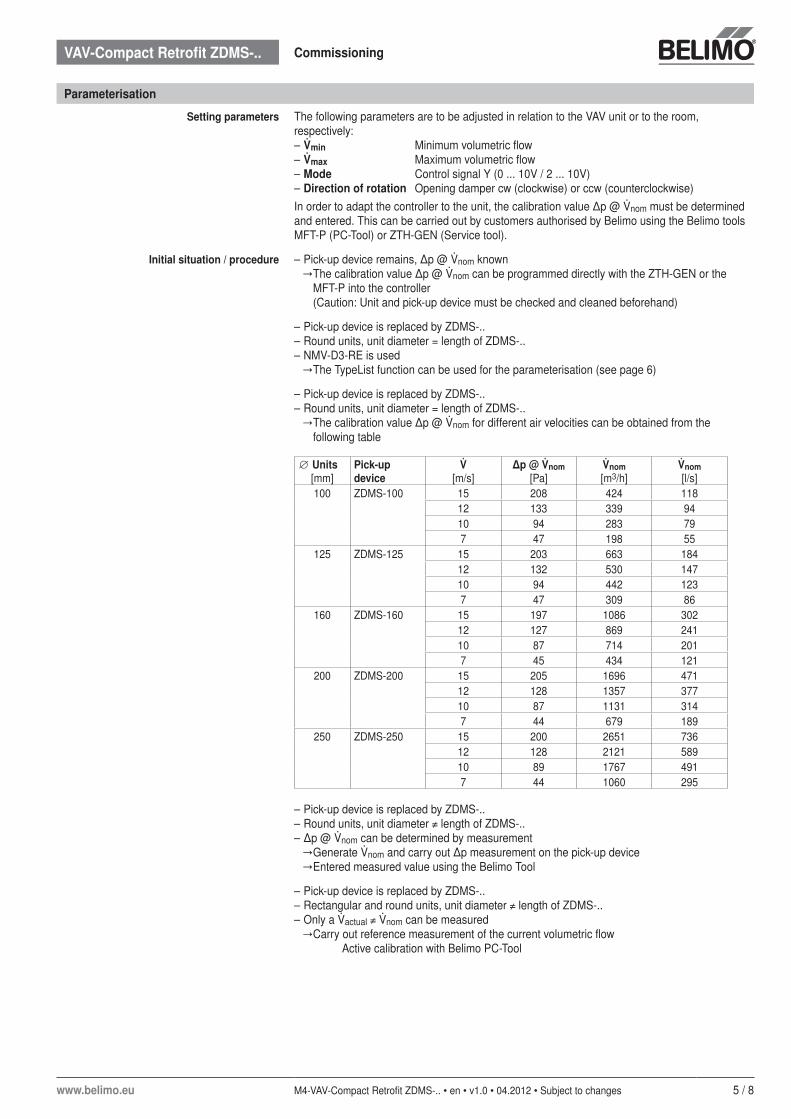
– Pick-up device is replaced by ZDMS-..– Round units, unit diameter = length of ZDMS-..
→ The calibration value ∆p @ nom for different air velocities can be obtained from the following table
∅ Units[mm]
Pick-up device
[m/s]
∆p @ nom[Pa]
nom[m3/h]
nom[l/s]
100 ZDMS-100 15 208 424 118 12 133 339 94 10 94 283 79 7 47 198 55
125 ZDMS-125 15 203 663 184 12 132 530 147 10 94 442 123 7 47 309 86
160 ZDMS-160 15 197 1086 302 12 127 869 241 10 87 714 201 7 45 434 121
200 ZDMS-200 15 205 1696 471 12 128 1357 377 10 87 1131 314 7 44 679 189
250 ZDMS-250 15 200 2651 736 12 128 2121 589 10 89 1767 491 7 44 1060 295
– Pick-up device is replaced by ZDMS-..– Round units, unit diameter ≠ length of ZDMS-..– ∆p @ nom can be determined by measurement
→ Generate nom and carry out ∆p measurement on the pick-up device→ Entered measured value using the Belimo Tool
– Pick-up device is replaced by ZDMS-..– Rectangular and round units, unit diameter ≠ length of ZDMS-..– Only a actual ≠ nom can be measured
→ Carry out reference measurement of the current volumetric flow Active calibration with Belimo PC-Tool
VAV-Compact Retrofit ZDMS-.. Commissioning
6 / 8 M4-VAV-Compact Retrofit ZDMS-.. • en • v1.0 • 04.2012 • Subject to changes www.belimo.eu
Parameterization with Belimo Service tool (ZTH-GEN)
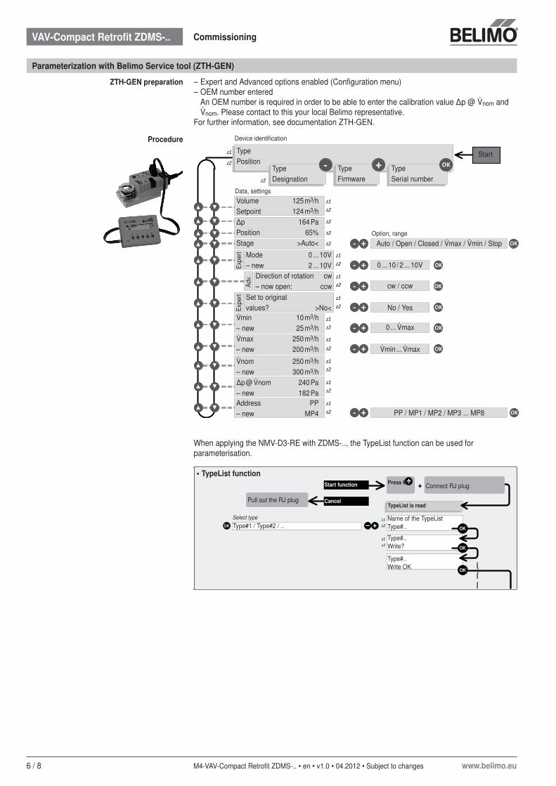
ZTH-GEN preparation – Expert and Advanced options enabled (Configuration menu)– OEM number entered An OEM number is required in order to be able to enter the calibration value ∆p @ nom and
nom. Please contact to this your local Belimo representative.For further information, see documentation ZTH-GEN.
Procedure
- + OK
z1z2▼
z2
z2
z2 +- OK
z1z2 +- OK
z1z2 +- OK
z1z2 +- OK
▼
▼
▼
▼
▼
▼
z1z2 +- OK▼
z1
z2
z2
▼
▼
▼
▼
▼
▼
▼
▼
z1z2 +- OK▼▼
+- OK
z1z2
▼▼
z1z2
▼▼z1z2
▼▼
When applying the NMV-D3-RE with ZDMS-.., the TypeList function can be used for parameterisation.
+
+–
+
OK
OK
OK
OK
z1z2
z1z2
Connect RJ plugPress keyStart function
CancelPull out the RJ plugTypeList is read
Type#1 / Type#2 / ..Name of the TypeListType#..
Type#..Write?
Type#..Write OK
Select type
• TypeList function
TypePosition
TypeSerial number
TypeFirmware
TypeDesignation
Auto / Open / Closed / max / min / Stop
Start
Data, settings
Option, range
Device identification
VolumeSetpoint
125 m3/h124 m3/h
∆pPositionStage
164 Pa65%
>Auto<
Mode– new
0 ... 10V2 ... 10V
min– new
10 m3/h25 m3/h
Address– new
PPMP4
cw / ccw
0 ... max
PP / MP1 / MP2 / MP3 ... MP8
Expe
rt
0 ... 10 / 2 ... 10V
No / YesSet to originalvalues? >No<Ex
pert
Direction of rotation– now open:
cwccwAd
v.
max– new
250 m3/h200 m3/h
nom– new
250 m3/h 300 m3/h
∆p @ nom– new
240 Pa 182 Pa
min ... max
VAV-Compact Retrofit ZDMS-.. Commissioning
www.belimo.eu M4-VAV-Compact Retrofit ZDMS-.. • en • v1.0 • 04.2012 • Subject to changes 7 / 8
Parameterisation with Belimo PC-Tool (MFT-P)
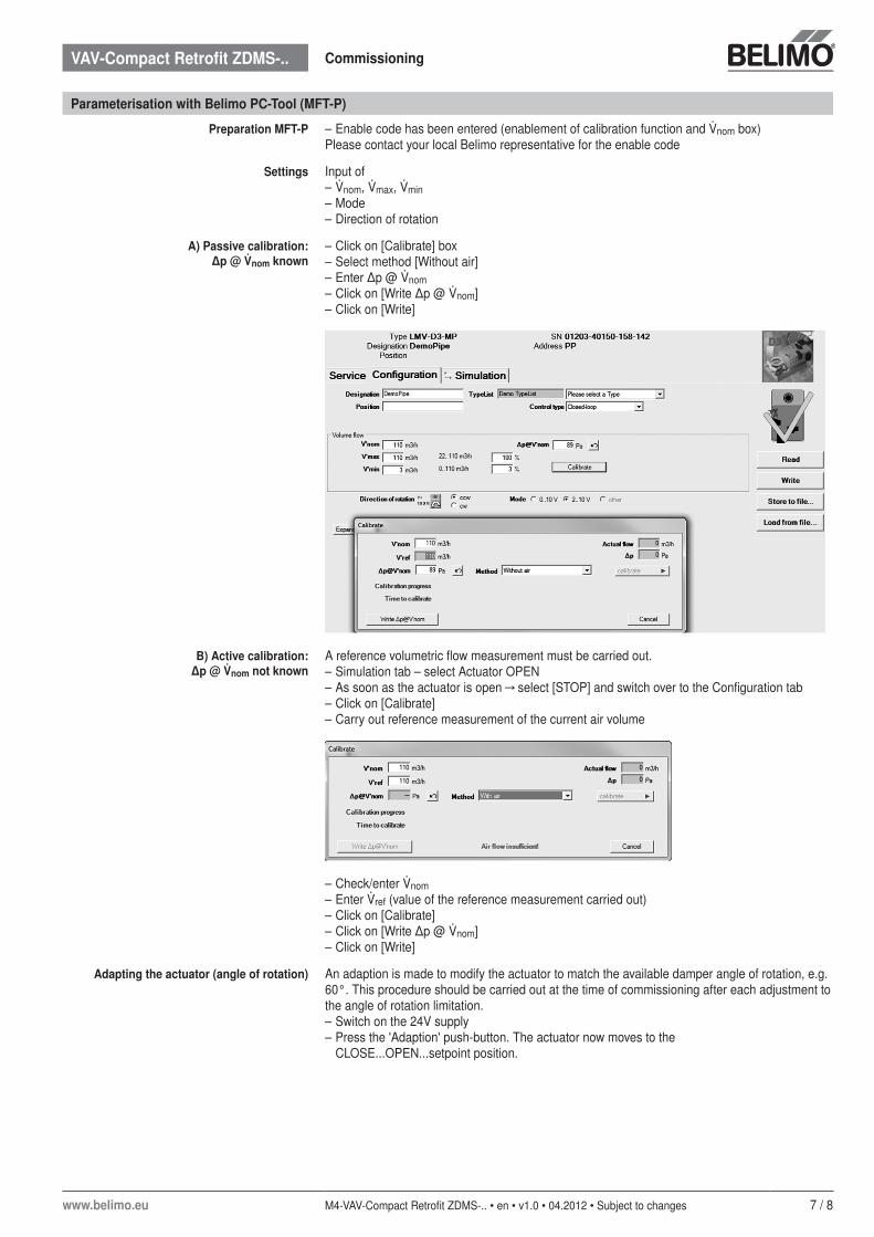
Preparation MFT-P – Enable code has been entered (enablement of calibration function and nom box)Please contact your local Belimo representative for the enable code
Settings Input of– nom, max, min– Mode– Direction of rotation
A) Passive calibration: ∆p @ nom known
– Click on [Calibrate] box– Select method [Without air]– Enter ∆p @ nom– Click on [Write ∆p @ nom]– Click on [Write]
B) Active calibration: ∆p @ nom not known
A reference volumetric flow measurement must be carried out.– Simulation tab – select Actuator OPEN– As soon as the actuator is open → select [STOP] and switch over to the Configuration tab– Click on [Calibrate]– Carry out reference measurement of the current air volume
– Check/enter nom– Enter ref (value of the reference measurement carried out)– Click on [Calibrate]– Click on [Write ∆p @ nom]– Click on [Write]
Adapting the actuator (angle of rotation) An adaption is made to modify the actuator to match the available damper angle of rotation, e.g. 60°. This procedure should be carried out at the time of commissioning after each adjustment to the angle of rotation limitation.– Switch on the 24V supply– Press the 'Adaption' push-button. The actuator now moves to the
CLOSE...OPEN...setpoint position.
VAV-Compact Retrofit ZDMS-.. Commissioning
8 / 8 M4-VAV-Compact Retrofit ZDMS-.. • en • v1.0 • 04.2012 • Subject to changes www.belimo.eu
Functional check
After the adjustment has been completed, it is recommended that a functional check be carried out on the VAV/CAV unit. The VAV controller is set to the desired operating mode with the ZTH-GEN and a setpoint/actual value comparison is made.
ZTH-GEN Stage selection Volume 400 m3/hStage >max<
Available stages CLOSED / min / max / Motor stop / OPEN
If the setpoint is not achieved Possible reasons:– No volumetric flow or negative ∆p value, respectively:
→ Pressure hoses incorrectly connected→ Direction of rotation set incorrectly→ Fire damper closed→ Ventilator does not run
– Actual volumetric flow is too low:→ Supply pressure too low (supply pressure control, FU setting, air performance too low)→ Damper spindle is mounted with an offset (damper cannot be opened all the way)
Extended energy-savings measure
Single room controlFan Optimiser System
Extended energy savings measures and comfort enhancements can be achieved through the utilisation of the BELIMO single room controller CR24.. and through the integration of the VAV system in a Fan Optimiser System
You will find more detailed information on these components and systems at the BELIMO web site www.belimo.eu or consult your local BELIMO representative.
VAV-Compact Retrofit ZDMS-.. Commissioning