w.belimoua b.prmuba sns,dbpgrimotav · vav-compact mod • en-gb • 2017-03 • changes reserved...
TRANSCRIPT
www.belimo.eu VAV-Compact MOD • en-gb • 2017-03 • Changes reserved 1
Product information VAV-Compact MOD
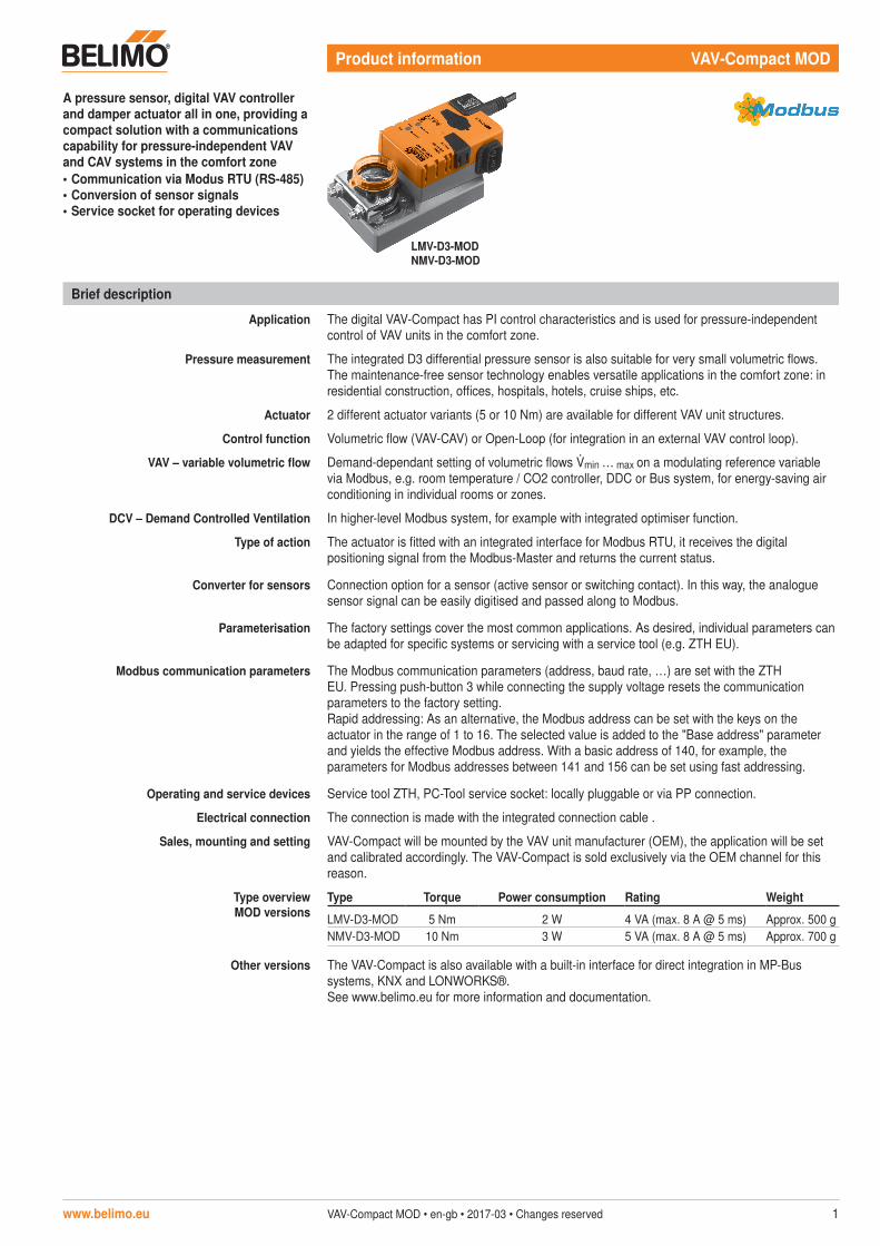
A pressure sensor, digital VAV controller and damper actuator all in one, providing a compact solution with a communications capability for pressure-independent VAV and CAV systems in the comfort zone• Communication via Modus RTU (RS-485)• Conversion of sensor signals• Service socket for operating devices
Brief description
Application The digital VAV-Compact has PI control characteristics and is used for pressure-independent control of VAV units in the comfort zone.
Pressure measurement The integrated D3 differential pressure sensor is also suitable for very small volumetric flows. The maintenance-free sensor technology enables versatile applications in the comfort zone: in residential construction, offices, hospitals, hotels, cruise ships, etc.
Actuator 2 different actuator variants (5 or 10 Nm) are available for different VAV unit structures.
Control function Volumetric flow (VAV-CAV) or Open-Loop (for integration in an external VAV control loop).
VAV – variable volumetric flow Demand-dependant setting of volumetric flows min … max on a modulating reference variable via Modbus, e.g. room temperature / CO2 controller, DDC or Bus system, for energy-saving air conditioning in individual rooms or zones.
DCV – Demand Controlled Ventilation In higher-level Modbus system, for example with integrated optimiser function.
Type of action The actuator is fitted with an integrated interface for Modbus RTU, it receives the digital positioning signal from the Modbus-Master and returns the current status.
Converter for sensors Connection option for a sensor (active sensor or switching contact). In this way, the analogue sensor signal can be easily digitised and passed along to Modbus.
Parameterisation The factory settings cover the most common applications. As desired, individual parameters can be adapted for specific systems or servicing with a service tool (e.g. ZTH EU).
Modbus communication parameters The Modbus communication parameters (address, baud rate, …) are set with the ZTH EU. Pressing push-button 3 while connecting the supply voltage resets the communication parameters to the factory setting.Rapid addressing: As an alternative, the Modbus address can be set with the keys on the actuator in the range of 1 to 16. The selected value is added to the "Base address" parameter and yields the effective Modbus address. With a basic address of 140, for example, the parameters for Modbus addresses between 141 and 156 can be set using fast addressing.
Operating and service devices Service tool ZTH, PC-Tool service socket: locally pluggable or via PP connection.
Electrical connection The connection is made with the integrated connection cable .
Sales, mounting and setting VAV-Compact will be mounted by the VAV unit manufacturer (OEM), the application will be set and calibrated accordingly. The VAV-Compact is sold exclusively via the OEM channel for this reason.
Type overview MOD versions
Type Torque Power consumption Rating Weight
LMV-D3-MOD 5 Nm 2 W 4 VA (max. 8 A @ 5 ms) Approx. 500 gNMV-D3-MOD 10 Nm 3 W 5 VA (max. 8 A @ 5 ms) Approx. 700 g
Other versions The VAV-Compact is also available with a built-in interface for direct integration in MP-Bus systems, KNX and LONWORKS®. See www.belimo.eu for more information and documentation.
LMV-D3-MOD NMV-D3-MOD

VAV-Compact MOD Volumetric flow compact control device for Modbus
2 VAV-Compact MOD • en-gb • 2017-03 • Changes reserved www.belimo.eu
Electrical installation
Notes– Supply via safety isolating transformer!– Modbus signal assignment: C1 = D– = A C2 = D+ = B– Supply and communication are not galvanically
isolated.– Connect earth signal for devices with one
another.
!No. Designation Wire colour Function
1
– T
blackAC/DC 24 V supply
2 ~ + red
35 MFT orange PP connection6 D– pink
Modbus (RS485)7 D+ grey
Safety notes
!• The device must not be used outside the specified field of application, especially
not in aircraft or in any other airborne means of transport.• Outdoor applications: possible only in the absence of direct effects on the actuator from
(sea)water, snow, ice, sunlight and aggressive gases and when it is guaranteed that the ambient conditions do not deviate at any time from the limit values specified in the datasheet.
• Only authorised specialists may carry out installation. All applicable legal or institutional installation regulations must be complied with during installation.
• The device may only be opened at the manufacturer's site. It does not contain any parts that can be replaced or repaired by the user.
• Cables must not be removed from the device.• When calculating the torque required, the specifications supplied by the damper
manufacturers (cross-section, construction, place of installation), and the ventilation conditions must be observed.
• The device contains electrical and electronic components and is not allowed to be disposed of as household refuse. All locally valid regulations and requirements must be observed.
See separate documentation for description of functions and applications
VAV-Compact MOD Volumetric flow compact control device for Modbus
www.belimo.eu VAV-Compact MOD • en-gb • 2017-03 • Changes reserved 3
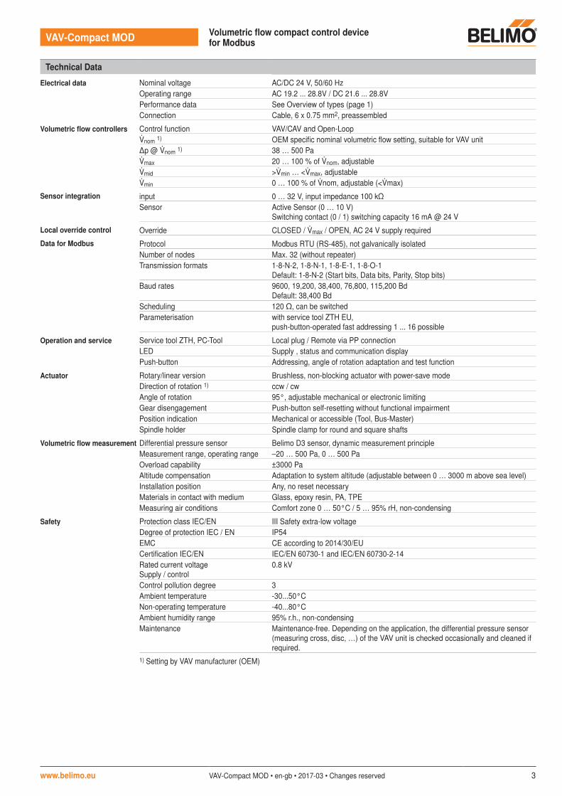
Technical Data
Electrical data Nominal voltage AC/DC 24 V, 50/60 HzOperating range AC 19.2 ... 28.8V / DC 21.6 ... 28.8VPerformance data See Overview of types (page 1)Connection Cable, 6 x 0.75 mm2, preassembled
Volumetric flow controllers Control function VAV/CAV and Open-Loopnom 1) OEM specific nominal volumetric flow setting, suitable for VAV unitΔp @ nom 1) 38 … 500 Pamax 20 … 100 % of nom, adjustablemid >min … <max, adjustable min 0 … 100 % of nom, adjustable (<max)
Sensor integration input 0 … 32 V, input impedance 100 kΩSensor Active Sensor (0 … 10 V)
Switching contact (0 / 1) switching capacity 16 mA @ 24 V
Local override control Override CLOSED / max / OPEN, AC 24 V supply required
Data for Modbus Protocol Modbus RTU (RS-485), not galvanically isolatedNumber of nodes Max. 32 (without repeater)Transmission formats 1-8-N-2, 1-8-N-1, 1-8-E-1, 1-8-O-1
Default: 1-8-N-2 (Start bits, Data bits, Parity, Stop bits)Baud rates 9600, 19,200, 38,400, 76,800, 115,200 Bd
Default: 38,400 BdScheduling 120 �, can be switchedParameterisation with service tool ZTH EU,
push-button-operated fast addressing 1 ... 16 possible
Operation and service Service tool ZTH, PC-Tool Local plug / Remote via PP connectionLED Supply , status and communication displayPush-button Addressing, angle of rotation adaptation and test function
Actuator Rotary/linear version Brushless, non-blocking actuator with power-save modeDirection of rotation 1) ccw / cwAngle of rotation 95°, adjustable mechanical or electronic limitingGear disengagement Push-button self-resetting without functional impairmentPosition indication Mechanical or accessible (Tool, Bus-Master)Spindle holder Spindle clamp for round and square shafts
Volumetric flow measurement Differential pressure sensor Belimo D3 sensor, dynamic measurement principleMeasurement range, operating range –20 … 500 Pa, 0 … 500 PaOverload capability ±3000 PaAltitude compensation Adaptation to system altitude (adjustable between 0 … 3000 m above sea level)Installation position Any, no reset necessaryMaterials in contact with medium Glass, epoxy resin, PA, TPEMeasuring air conditions Comfort zone 0 … 50°C / 5 … 95% rH, non-condensing
Safety Protection class IEC/EN III Safety extra-low voltageDegree of protection IEC / EN IP54EMC CE according to 2014/30/EUCertification IEC/EN IEC/EN 60730-1 and IEC/EN 60730-2-14Rated current voltageSupply / control
0.8 kV
Control pollution degree 3Ambient temperature -30...50°CNon-operating temperature -40...80°CAmbient humidity range 95% r.h., non-condensingMaintenance Maintenance-free. Depending on the application, the differential pressure sensor
(measuring cross, disc, …) of the VAV unit is checked occasionally and cleaned if required.
1) Setting by VAV manufacturer (OEM)

VAV-Compact MOD Volumetric flow compact control device for Modbus
4 VAV-Compact MOD • en-gb • 2017-03 • Changes reserved www.belimo.eu
Modbus overview
Register No. Adr Register
Ope
ratio
n
1 0 Setpoint [%]2 1 Override control3 2 Command4 3 Actuator type 5 4 Relative position [%]6 5 Absolute position [°] [mm]7 6 Relative volumetric flow [%]
(only for VAV/EPIV)8 7 Absolute volumetric flow (pressure) [m3/h] [l/min] [Pa]
(only for VAV/EPIV)9 8 Sensor value [mv] [–]
Serv
ice
101 100 Series number 1st part102 101 Series number 2nd part103 102 Series number 4th part104 103 Firmware version (Modbus module)105 104 Malfunction and service information106 105 Min [%]107 106 Max [%]108 107 Sensor type109 108 Bus fail position110 109 -111 110 Nominal volumetric flow (pressure) [m3/h] [l/min] [Pa]
(only for VAV/EPIV)
• Registers in Bold can be written• Registers <100 (In operation) which can be written are non-permanent and should therefore be
updated periodically• Registers >100 which can be written are not non-permanent
Commands All data is arranged in a table and addressed by 1..n (register) or 0..n-1 (address). No distinction is made between data types (Discrete Inputs, Coils, Input Registers, Holding Registers). As a consequence, all data can be accessed with the two commands for Holding Register. The commands for Discrete Inputs and Input Registers can be used as an alternative.Standard commands:Read Holding Registers [3]Write Single Register [6]Optional commands:Read Discrete Inputs [2]Read Input Registers [4]Write Multiple Registers [16]
Note regarding Read Discrete InputsThe command reads one or more bits and can alternatively be used for register 105 (Malfunction and service information). The start address to be used is 1664.

VAV-Compact MOD Volumetric flow compact control device for Modbus
www.belimo.eu VAV-Compact MOD • en-gb • 2017-03 • Changes reserved 5
Modbus register description
Register 1: Setpoint Setpoint for actuator setting or volumetric flow in hundredths of one percent, i.e. 0 … 10 000 correspond to 0 … 100%
Register 2: Override control Overriding the setpoint with defined compulsionsOverride control
0 None1 Open2 Close3 Min5 Max
Register 3: Command Initiation of actuator functions for service and test; the register is reset automatically.Command
0 None1 Adaptation2 Test run3 Synchronisation4 Reset actuator malfunctions
Register 4: Actuator type Actuator type; the allocation may deviate from the basic category with some actuators.Actuator type
0 Actuator not connected / not known1 Air/water actuators with/without safety function2 Volumetric flow controller VAV / EPIV3 Fire protection actuator
Register 5: Relative position Relative position in hundredths of one percent, i.e. 0 … 10 000 correspond to 0 … 100%
Register 6: Absolute position Absolute position 0 … 10 000 (65535 if not supported by the actuator)The unit depends on the device:[°] for actuators with rotary movement[mm] for actuators with linear movement
Register 7: Relative volumetric flow Relative volumetric flow in hundredths of one percent of Vnom,i.e. 0 … 10 000 correspond to 0 … 100%This value is available only for VAV controllers and EPIV devices (actuator type: 2).For all other types, 65535 will be entered.
Register 8: Absolute volumetric flow Absolute volumetric flowThis value is available only for VAV controllers and EPIV devices (actuator type: 2).For all other types, 65535 will be entered.The unit depends on the device: [m3/h] for VAV controllers (or [Pa] for pressure applications)[l/min] for EPIV devices
Register 9: Sensor value Current sensor value; dependent on the setting in Register 108The unit depends on the sensor type: [mv] [-]
Register 101 to 103: Series number Each device has an unambiguous series number which is either impressed on or glued to the housing. The series number consists of 4 segments, although only parts 1, 2 and 4 are displayed on Modbus.Example: 00839-31324-064-008
Register 101 Register 102 Register 1031st part 2nd part 4th part00839 31234 008
Register 104: Firmware Version Firmware version of Modbus module (VX.XX)e.g. 101 V1.01

VAV-Compact MOD Volumetric flow compact control device for Modbus
6 VAV-Compact MOD • en-gb • 2017-03 • Changes reserved www.belimo.eu
Modbus register description
Register 105: Malfunction and service information
The status information is split into messages about the actuator (malfunctions) and other service information.
bit Description
Mal
func
tions
(low
byt
e) 0 Utilisation too high 1 Actuation path increased 2 Mechanical overload3 –4 Safety-relevant malfunction (fire protection only)5 Damper mobility fault (fire protection only)6 Channel temperature too high (fire protection only)7 Smoke detector tripped (fire protection only)
Serv
ice
(hig
h by
te)
8 Internal activity (test run, adaptation, …)9 Gear disengagement active
10 Bus monitoring triggered11 –12 –13 –14 –15 –
The malfunction bits can be reset with Register 3 (command 4) or with the Belimo PC-Tool. Malfunctions 0 and 4 cannot be reset.
Register 106: Min / Vmin setting Minimum limit (position or volumetric flow) in hundredths of one percent, i.e. 0 … 10 000 correspond to 0 … 100%Caution: Changing the setting may result in malfunctions.
Register 107: Max / Vmax setting Minimum limit (position or volumetric flow) in hundredths of one percent, i.e. 2000 … 10 000 correspond to 20 … 100%Caution: Changing the setting may result in malfunctions.
Register 108: Sensor type Sensor type connected to the actuator; in the absence of sensor specification, the switching at the Y input will have the effect of a local compulsion.Sensor type
0 None1 Active sensor (mV)2 –3 –4 Switching contact (0 / 1)
Register 109: Bus fail position Modbus communication is not monitored as standard. In the event of a breakdown in communication, the actuator retains the current setpoint.The bus monitoring controls the Modbus communication. If neither the setpoint (Register 1) nor the override control (Register 2) is renewed within 120 seconds, the actuator controls to the bus fail position. Triggered bus monitoring is indicated in Register 105.Bus fail position
0 Last setpoint (no bus monitoring)1 Rapid close if time is exceeded2 Rapid open if time is exceeded3 Intermediate position Mid is parameterised for time delay
Register 110: (Reserved) Not used in this device
Register 111: Nominal volumetric flow This value is available only for VAV controllers and EPIV devices (actuator type: 2). The nominal volumetric flow is determined by the manufacturer of the volume flow box. For all other types, 65535 will be entered. The unit depends on the device: [m3/h] for VAV controllers (or [Pa] for pressure applications) [l/min] for EPIV devices
Note– After changing the sensor type, the actuator must
always be restarted in order for correct sensor values to be read out.
– Sensor values are not available for actuator versions with RJ12 connection socket (J6) since no sensor connection is possible.

VAV-Compact MOD Volumetric flow compact control device for Modbus
www.belimo.eu VAV-Compact MOD • en-gb • 2017-03 • Changes reserved 7
Modbus Wiring
1 2 3 5 6 7
Modbus (RS-485)
MFT D+D –+
~
–
T
AC/DC 24 V
D +D –
1 2 3 5 6 7
MFT D+D –+
~
–
T
AC/DC 24 VSlave 1 Slave 32
GND
Master
Connection with switching contact, e.g. ∆p-monitor Connection of active sensors, e.g. 0...10 V @ 0...50°C
1 2
+
~
–
T
3 5 6 7
∆p
MFT D+D –
Modbus (RS-485)D –D +
Switching contact requirements: The switching contact must be able to switch a current of 16 mA at 24V accurately.
1 2
+
~
–
T
3 5 6 7
MFT D+D –
Modbus (RS-485)D –D +
Possible voltage range:0 ... 32 V (resolution 30 mV)
Local override controlIf no sensor is integrated, then connection 3 (Y) is available for the protective circuit of a local override control.Options: CLOSED – max – OPENNote: Functions only with AC 24V supply!
1 2 3 5
~T
Y
a b c d
MFT D+D –
6 7
Modbus (RS-485)D –D +
a Damper CLOSEDb Maxc Damper OPENd Bus mode
Electrical installation
!Notes • Connection via safety isolating transformer.
The wiring of Modbus RTU (RS485) is to be carried out in accordance with applicable regulations (www.modbus.org). The device has connectible resistances for the bus connection,
• Modbus-GND: Supply and communication are not galvanically isolated. Connect earth signal for devices with one another.
Modbus signal assignment: C₁ = D- = A C₂ = D+= B

VAV-Compact MOD Volumetric flow compact control device for Modbus
8 VAV-Compact MOD • en-gb • 2017-03 • Changes reserved www.belimo.eu
Control functions - VAV / CAV
VAV-operating volumetric flow – Setting and control Open-Loop (separate external VAV-Control)
0%
nom
max
100%
20%
0%
0% 100%
min
<max
Reference signal Modbus
Ran
ge
min
Ran
ge
max
100%
0%0 100%20 40 60 80 Reference signal Modbus
Control damper Y
VAV-Compact MOD Volumetric flow compact control device for Modbus
www.belimo.eu VAV-Compact MOD • en-gb • 2017-03 • Changes reserved 9
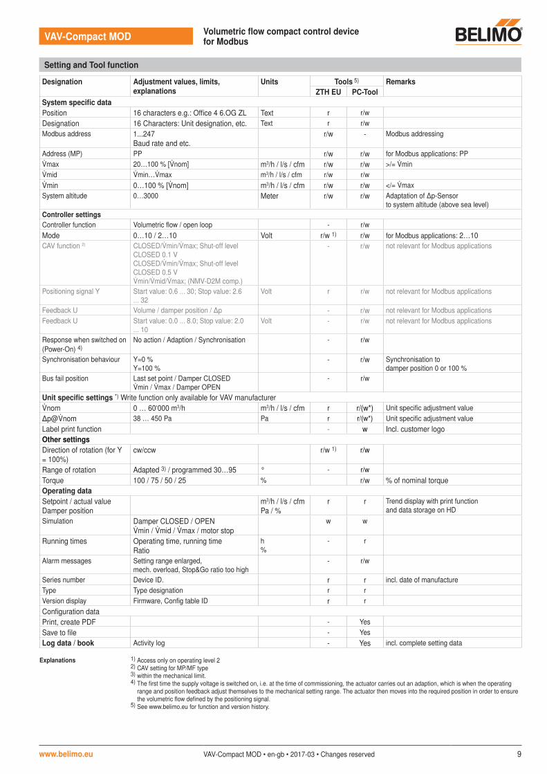
Setting and Tool function
Designation Adjustment values, limits, explanations
Units Tools 5) RemarksZTH EU PC-Tool
System specific dataPosition 16 characters e.g.: Office 4 6.OG ZL Text r r/wDesignation 16 Characters: Unit designation, etc. Text r r/wModbus address 1...247
Baud rate and etc.r/w - Modbus addressing
Address (MP) PP r/w r/w for Modbus applications: PPmax 20…100 % [nom] m3/h / l/s / cfm r/w r/w >/= minmid min…max m3/h / l/s / cfm r/w r/wmin 0…100 % [nom] m3/h / l/s / cfm r/w r/w </= maxSystem altitude 0…3000 Meter r/w r/w Adaptation of Δp-Sensor
to system altitude (above sea level) Controller settingsController function Volumetric flow / open loop - r/wMode 0…10 / 2…10 Volt r/w 1) r/w for Modbus applications: 2…10CAV function 2) CLOSED/min/max; Shut-off level
CLOSED 0.1 VCLOSED/min/max; Shut-off level CLOSED 0.5 Vmin/mid/max; (NMV-D2M comp.)
- r/w not relevant for Modbus applications
Positioning signal Y Start value: 0.6 … 30; Stop value: 2.6 … 32
Volt r r/w not relevant for Modbus applications
Feedback U Volume / damper position / Δp - r/w not relevant for Modbus applicationsFeedback U Start value: 0.0 … 8.0; Stop value: 2.0
… 10 Volt - r/w not relevant for Modbus applications
Response when switched on(Power-On) 4)
No action / Adaption / Synchronisation - r/w
Synchronisation behaviour Y=0 %Y=100 %
- r/w Synchronisation to damper position 0 or 100 %
Bus fail position Last set point / Damper CLOSEDmin / max / Damper OPEN
- r/w
Unit specific settings *) Write function only available for VAV manufacturernom 0 … 60‘000 m3/h m3/h / l/s / cfm r r/(w*) Unit specific adjustment valueΔp@nom 38 … 450 Pa Pa r r/(w*) Unit specific adjustment valueLabel print function - w Incl. customer logoOther settings Direction of rotation (for Y = 100%)
cw/ccw r/w 1) r/w
Range of rotation Adapted 3) / programmed 30…95 ° - r/wTorque 100 / 75 / 50 / 25 % r/w % of nominal torqueOperating dataSetpoint / actual valueDamper position
m3/h / l/s / cfmPa / %
r r Trend display with print function and data storage on HD
Simulation Damper CLOSED / OPENmin / mid / max / motor stop
w w
Running times Operating time, running timeRatio
h%
- r
Alarm messages Setting range enlarged, mech. overload, Stop&Go ratio too high
- r/w
Series number Device ID. r r incl. date of manufactureType Type designation r rVersion display Firmware, Config table ID r rConfiguration dataPrint, create PDF - YesSave to file - YesLog data / book Activity log - Yes incl. complete setting data
Explanations 1) Access only on operating level 22) CAV setting for MP/MF type3) within the mechanical limit.4) The first time the supply voltage is switched on, i.e. at the time of commissioning, the actuator carries out an adaption, which is when the operating
range and position feedback adjust themselves to the mechanical setting range. The actuator then moves into the required position in order to ensure the volumetric flow defined by the positioning signal.
5) See www.belimo.eu for function and version history.

VAV-Compact MOD Volumetric flow compact control device for Modbus
10 VAV-Compact MOD • en-gb • 2017-03 • Changes reserved www.belimo.eu
Fast addressing Modbus 1. Hold the "Service" button pressed down until the green "Power" LED display is no longer illuminated. The green "Adaption" LED display flashes in accordance with the previously set address.
2. Set the address by pressing the "Service" button the corresponding number of times (1-16).3. The green LED display flashes in accordance with address that has been entered (1-16). If the
address is not correct, then this can be reset in accordance with Step 2.4. Confirm the address setting by pressing the green "Adaption" button.If no confirmation occurs for 60 seconds, then the address procedure is ended. Any address change that has already been started will be discarded.The resulting Modbus address is made up of the set basic address plus the short address (e.g. 140+7=147).
ZTH / PC-Tool - local service connection The settings and diagnostics of the VAV-Compact can be performed easily and rapidly with the Belimo PC-Tool or with the ZTH-EU service tool. When using the PC-Tool, the ZTH EU serves as an interface converter.
BELIMOPC-Tool
USB
MP
USB � �i esc OK
ZTH EU
RJ12ZK1-GEN
AC 24 VDC 24 V
1 2
+
~
–
T
3 5 6 7
MFT D+D –
ZTH EU(or ZIP-USB-MP)
Download PC-Tool (MFT-P) from www.belimo.eu
Display and operation
AdaptionPower
Status
3
1
2
4
Address
1 Push-button and LED display greenOff:On:Flashing:
Press button:
No power supply or malfunctionIn operationIn address mode: Pulses according to set address (1 ... 16)When starting: Reset to factory setting (Communication)In standard mode: Triggers angle of rotation adaptationIn address mode: Confirmation of set address (1 ... 16)
2 Push-button and LED display yellowOff:On:
Flickering:Press button:
Standard modeAdaption or synchronising process activeor actuator in address mode (LED display green flashing)Modbus communication activeIn operation (>3 s): Switch address mode on and offIn address mode: Address setting by pressing several timesWhen starting (>5 s): Reset to factory setting (Communication)
3 Gear disengagement buttonPress button:Release button:
Gear disengaged, motor stops, manual override possibleGear engaged, synchronisation starts, followed by standard mode
4 Service plugFor connecting parameterisation and service tools
Check power supply connection
1 Off and 2 On Possible wiring error in power supply

VAV-Compact MOD Volumetric flow compact control device for Modbus
www.belimo.eu VAV-Compact MOD • en-gb • 2017-03 • Changes reserved 11
VAV-Compact / VAV-Universal Description
VAV-Compact: version with integrated MP-Bus, LONWORKS® and KNX interfaceVAV-Universal: VAV pressure controller, ∆p sensors, actuator(spring-return, fast runner, etc.)see www.belimo.eu for more information and documentation
Electrical accessories Description Type
Connection cable 5 m, to ZTH / ZIP-USB-MP (RJ12) with service plug ZK1-GENConnection cable 5 m, to ZTH / ZIP-USB-MP (RJ11) with free wire ends ZK2-GEN
Tools Description Type
Service Tool, for MF/MP/Modbus/LONWORKS actuators and VAV controllers ZTH EUBelimo PC-Tool, software for adjustments and diagnostics MFT-P
Accessories
Dimensions [mm]
Dimensional drawings LMV-D3-MOD Dimensional drawings NMV-D3-MOD
116
61
11622
66
41
12125
80
41
12462
Further documentation
• Tool connections
Display and operation
ZTH / PC-Tool - remote connection The VAV-Compact can communicate with the service tools via the PP connection (wire 5). The connection can be made in operating mode in the junction box or the control cabinet terminals. When using the PC-Tool, the ZTH EU serves as an interface converter.
AC 24 VDC 24 V
1 2
+
~
–
T
3 5 6 7
BELIMOPC-Tool
USB
MP
USB � �i esc OK
ZTH EU
RJ11ZK2-GEN
GND
PP
MFT D+D –
white = GND green = PP
ZTH EU (or ZIP-USB-MP)
blue, do not connect
Download PC-Tool (MFT-P) from www.belimo.eu

12 VAV-Compact MOD • en-gb • 2017-03 • Changes reserved www.belimo.eu
VAV-Compact MOD VAV-Compact Model overview / feature comparison
-MF -MP -KNX LON -MOD
Field of application: Supply and exhaust air in the comfort zone and sensor-compatible media
X X X X X
AC/DC 24 V supply X X X X X
Integrated Δp sensor, dynamic D3, measuring range:
–20 … 500 Pa
–20 … 500 Pa
–20 … 500 Pa
–20 … 500 Pa
–20 … 500 Pa
Actuator variants: – Rotary actuator 5 / 10 Nm 5 / 10 / 20 Nm 5 / 10 / 20* Nm 5 / 10 / 20* Nm 5 / 10 / 20* Nm– Linear actuator – 150 / 200 / 300 mm 150* / 200* / 300* mm 150* / 200* / 300* mm 150* / 200* / 300* mm
VAV function min … max X X X X X
CAV stages min / mid / max X X – – –
Open Loop (external V control) X X X X X
DCV (Optimiser function) – DDC MP PartnersBelimo fan optimiser Yes, programmable Yes, programmable Yes, programmable
Analog control 0/2 ... 10 V 0/2 ... 10 V – – –
With bus control – X X X X
Bus specification – Belimo MP bus KNXS mode
LONWORKS®
FTT-10AModbus RTU
RS485
Direct integration DDC MP Partners – X – – –
Integration via Gateway – – – –– BACnet X– KNX X– LONWORKS® X– Modbus RTU X
Number of bus devices – 8 per strand 64 per line segment 64 per bus segment 32 per strand
Sensor integration –– passive (resistance) X – – –– active (0…10 V) X X X X– Switching contact X X X X
Optional control function – – – Temperature / CO2 –
Local forced (override) – CLOSED / max / OPEN
CLOSED / max / OPEN
CLOSED / max / OPEN
CLOSED / max / OPEN
Aids – MP-Bus TesterMP Monitor
ETSProduct database – –
Integration tools – PC-Tool ETS LNS Tool + Plug-in …
TypeList function (Retrofit, OEM) – X (–) (–) (–)
Tool connection (U – PP/MP) PP PP/MP PP PP PP
Service socket ZTH / PC-Tool X X X X X
NFC interface – X – – –
Assistant App – X – – –
Service tool ZTH EU X X X X X
PC-Tool X X X X X– Parameter– Save data– Trend, Logbook– Label Print
* on request