asv215bf152*: vav compact controller for laboratory and
TRANSCRIPT
ASV215BF152*: VAV compact controller for laboratory andpharmaceutical applications
How energy efficiency is improvedAllows demand-based volume flow control in order to optimise energy consumption in ventilation sys-tems. Differential pressures of at least 1 Pa can be controlled to allow minimal volume flows at thelowest duct pressure and energy consumption
Features• Controlling the return air in fume cupboards and controlling the supply and return air in laboratories,
clean rooms, hospital wards and operating theatres using a VAV box or a damper and flow probe• Static measurement of differential pressure based on the capacitive method of measurement• Zero point can be calibrated using software• Adjustable end values of the differential pressure measuring range1)
• 50...150 Pa• 100...300 Pa
• Can be used for measuring in areas with dirty or contaminated return air• Brushless DC motor guarantees minimum energy consumption and a long service life• Electromechanical torque-based switch-off for safe operation• Extremely simple installation due to self-centring shaft adapter• Disengageable gear unit for manual adjustment and positioning of damper• Easy programming of the following applications using SAUTER CASE Components:2)
• Volume flow control• Room pressure control• Duct pressure control• Flow control for fume cupboards
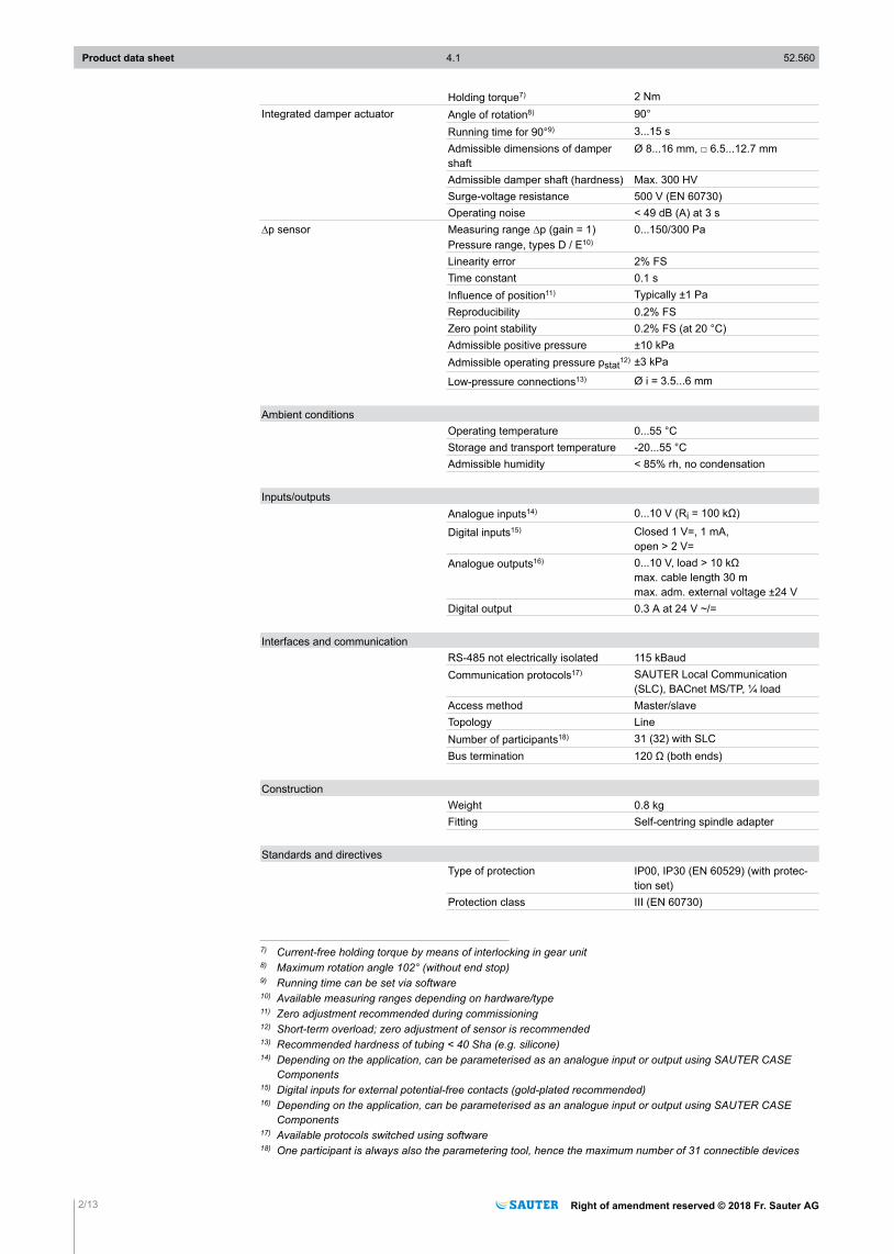
• Efficient control algorithm for fast control loops• Integrated second control loop for:3)
• Room-pressure control: can be ideally combined with EGP 100 with symmetrical measuringrange
• Fume-cupboard control ideally combined with SVU 100, SGU 100 and FCCP 200• 2 x RS-485 bus interface on RJ12 and connection terminal
• Up to 31 subscribers in a segment with SLC (SAUTER Local Communication) protocol• Communication within network via BACnet MS/TP4)
• Integration of EY-RU 3** digital room operating units• FCCP 200 display and alarm unit for fume-cupboard control or room monitoring
• Input and output signals for integrating:• Setpoints and actual values• Analogue output• Priority control via switching contacts
Technical data
Power supplyTorque 10 NmPower supply5) 24 V~, ±20%, 50...60 Hz
24 V=, -10%/+20%Power consumption at nominalvoltage 50/60 Hz (~/=) after 3 srunning time
Power consumption during operation Approx. 19 VA/10 W (10 Nm) Approx. 20 VA/11 W with FCCP 200
Power consumption when idle6) Approx. 6 VA/2 W
ParametersTorque 10 Nm
1) Available measuring ranges depending on hardware/type2) Application support depending on hardware and software version in CASE VAV manual3) Application support depending on hardware and software version in CASE VAV manual4) Support of BACnet MS/TP interface5) 24 V=: Analogue inputs that are not connected are rated 0 V. The nominal torque is achieved within the speci-
fied tolerances.6) Holding torque approx. 5 Nm
Product data sheet 4.1 52.560
Right of amendment reserved © 2018 Fr. Sauter AG 1/13
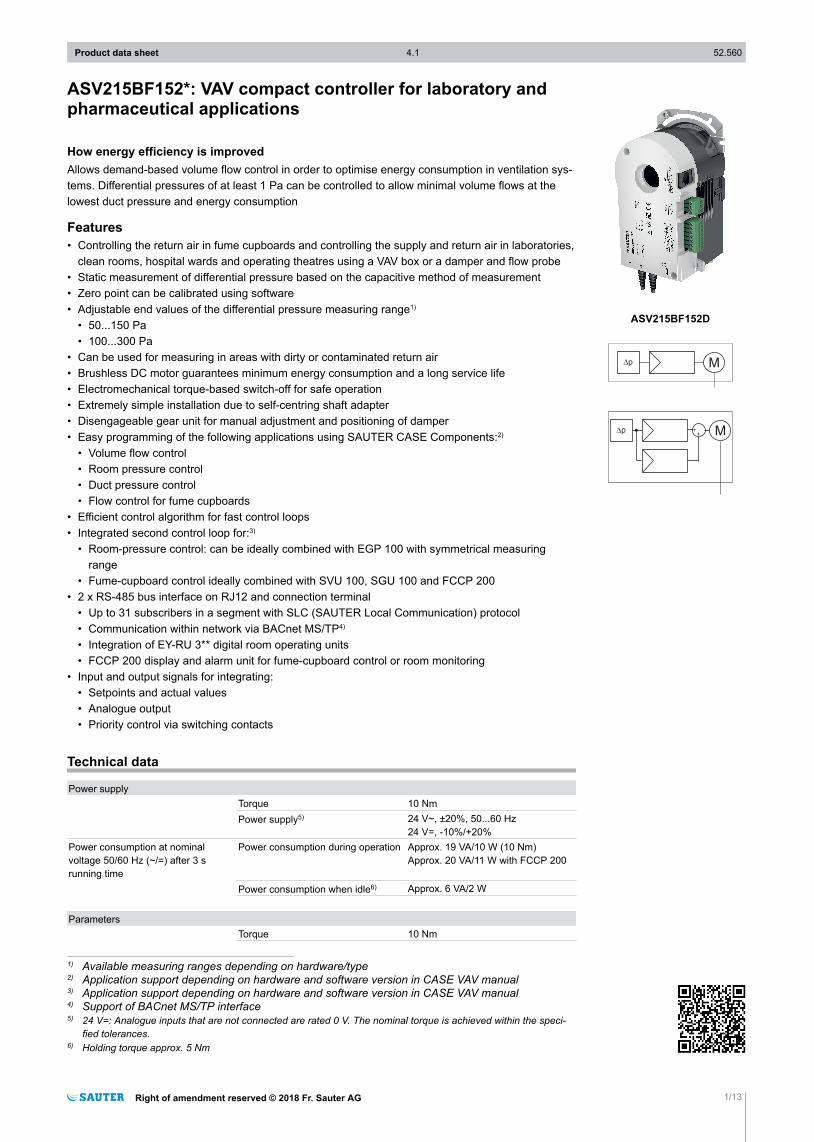
ASV215BF152D
++
Holding torque7) 2 NmIntegrated damper actuator Angle of rotation8) 90°
Running time for 90°9) 3...15 sAdmissible dimensions of dampershaft
Ø 8...16 mm, □ 6.5...12.7 mm
Admissible damper shaft (hardness) Max. 300 HVSurge-voltage resistance 500 V (EN 60730)Operating noise < 49 dB (A) at 3 s
∆p sensor Measuring range ∆p (gain = 1)Pressure range, types D / E10)
0...150/300 Pa
Linearity error 2% FSTime constant 0.1 sInfluence of position11) Typically ±1 PaReproducibility 0.2% FSZero point stability 0.2% FS (at 20 °C)Admissible positive pressure ±10 kPaAdmissible operating pressure pstat12) ±3 kPa
Low-pressure connections13) Ø i = 3.5...6 mm
Ambient conditionsOperating temperature 0...55 °CStorage and transport temperature -20...55 °CAdmissible humidity < 85% rh, no condensation
Inputs/outputsAnalogue inputs14) 0...10 V (Ri = 100 kΩ)
Digital inputs15) Closed 1 V=, 1 mA,open > 2 V=
Analogue outputs16) 0...10 V, load > 10 kΩmax. cable length 30 mmax. adm. external voltage ±24 V
Digital output 0.3 A at 24 V ~/=
Interfaces and communicationRS-485 not electrically isolated 115 kBaudCommunication protocols17) SAUTER Local Communication
(SLC), BACnet MS/TP, ¼ loadAccess method Master/slaveTopology LineNumber of participants18) 31 (32) with SLCBus termination 120 Ω (both ends)
ConstructionWeight 0.8 kgFitting Self-centring spindle adapter
Standards and directivesType of protection IP00, IP30 (EN 60529) (with protec-
tion set)Protection class III (EN 60730)
7) Current-free holding torque by means of interlocking in gear unit8) Maximum rotation angle 102° (without end stop)9) Running time can be set via software10) Available measuring ranges depending on hardware/type11) Zero adjustment recommended during commissioning12) Short-term overload; zero adjustment of sensor is recommended13) Recommended hardness of tubing < 40 Sha (e.g. silicone)14) Depending on the application, can be parameterised as an analogue input or output using SAUTER CASE
Components15) Digital inputs for external potential-free contacts (gold-plated recommended)16) Depending on the application, can be parameterised as an analogue input or output using SAUTER CASE
Components17) Available protocols switched using software18) One participant is always also the parametering tool, hence the maximum number of 31 connectible devices
Product data sheet 4.1 52.560
2/13 Right of amendment reserved © 2018 Fr. Sauter AG
Conformity Machine directive 2006/42/EC, ap-pendix II 1.B
EMC Directive 2014/30/EU EN 61000-6-1, EN 61000-6-3,EN 61000-6-4, EN 61000-6-2
Overview of typesType Measuring range ∆p
ASV215BF152D 0...150 Pa
ASV215BF152E 0...300 Pa
AccessoriesType Description
0372301001 Spindle adaptor for squared end hollow profile (x 15 mm), pack of 10 pcs.
XAFP100F001 Flow probe to measure the air volume in ventilation ducts
0300360001 USB connection set
0297867001 Reference pressure container
0430360100 IP30 protection set
0430360200 Replacement LP connector
0372129001 Torsion protection
Description of operationThe ASV 215 is a VAV compact controller for the supply- and return-air control in fume cupboards andthe supply- and return-air control in laboratories, clean rooms, hospital wards and operating theatres.The ASV 215 may only be used for the intended purposes stated here.The pressure difference generated at an orifice plate or Pitot tube is recorded by a static differentialpressure sensor and converted to a flow-linear signal. An external command signal cqV.s is limited bythe parameterised minimum and maximum settings and compared to the actual volume flow rqV.Based on the measured control deviation, the actuator moves the damper on the VAV box until thevolume flow across the measuring point reaches the required level. Without an external commandsignal, the volume flow setpoint corresponds to parameter mmin (factory setting). The application andinternal parameters are configured using the SAUTER CASE Components PC software. The softwareallows you to configure the compact controller specifically for the application and to set the necessaryparameters in bus mode.
ASV 2*5 connectionBlock Signal ASV 215BF152
1 LS Power supplyMM System ground01 AI/AO 0...10 V02 AI/AO 0...10 V03 AI/AO 0...10 V04 DI/DO05 DI
2 06 RS-485 D-A07 RS-485 D+A08 RS-485 Common
3RJ-12
06 RS-485 D-B05 RS-485 D+B04 RS-485 D-A03 RS-485 D+A02 Cout
01 5 V=out
Product data sheet 4.1 52.560
Right of amendment reserved © 2018 Fr. Sauter AG 3/13
Example application VAV.10.101.MThe VAV compact controller is shipped from the factory with the following default configuration.The inputs and outputs are preconfigured according to the table.
Connection assignment (factory setting). Application VAV10.101.MConnection Function Designation Setting range01 External command variable cqV.s 0…10 V (0…100% mnom)
02 Setpoint shift cqV.p.ad 5 V ± 5 V Ξ ± 100% mnom
03 Volume flow actual value rqV 0…10 V (0…100%) mnom
04 Priority control cqV.p.1 (actuated condition) Closed 1 V=, 1 mA Open > 2 V=
05 Priority control cqV.p.2 (actuated condition) Closed 1 V=, 1 mA Open > 2 V=
Volume flow characteristicsTo configure the device, the design data of the VAV box must be loaded to the actuator using theSAUTER CASE Components software. At least the following data is required for this:
Box DN BoxC factor
mn AT mnom mmax mmin
Unit mm l/s - m3/h l/s - m3/h l/s - m3/h l/s - m3/h l/s - m3/h
Setting the operating volume flowsThe following functions are available for operating the VAV controller:
Volume flow control setting rangesFunction Volume flow / damper
positionMaximumsetting ranges
Recommended setting ranges
Damper closed Damper fully closed 0° damper position
mmin Minimum m1Pa19)...mmax 10…100% mmax
mmax Maximum m1Pa…mnom 10…100% mnom
mmid Intermediate position mmax > mmid > mmin 10…100% max
Damper open Damper fully open 90° damper position
mnom Nominal volume flow Specific value, depending on box type, air density and applica-tion
mint Internal setpoint m1Pa…mnom 10…100% mnom
Functions of the ASV with VAV.10.101.MAnalogue input (AI 01)VAV controller command signalThe mmin and mmax values, which must be configured using the software, provide lower and upper lim-its for the command signal cqV.s.Analogue input/output (AI/AO 02)For the analogue input and output terminal AI/AO 02, an input function or one of two output functionscan be selected.Volume flow setpoint shift cqV.p.adThe setpoint for the volume flow is defined at output AI 01. A room-pressure controller, for example,or the setpoint shift of the VAV compact controller, is controlled by the input signal of terminal AI 02.The input signals can be 0…10 V, 0…100% or user-defined ±100%.Flow control deviation -eqV.sOutput AO 02 can be used for notification if the volume flow deviates from the command variablecqV.s. The current control deviation can be recorded as a voltage. If the setpoint is equal to the actualvalue, the output voltage is 5 V.
19) Volume flow that generates a differential pressure of 1 Pa
Product data sheet 4.1 52.560
4/13 Right of amendment reserved © 2018 Fr. Sauter AG
)NoteHalf slope (±100%, 0.05 V/% compared to 0.1 V/%) results in double the neutral zone (= green zone Ξ noalarm) for alerting.
Damper position rPhiOutput AO 02 can also be changed to indicate the current damper position using CASE Components.The working range of the damper-actuator combination can be scaled freely as 0...100% from a mini-mum of 0 V to a maximum of 10 V.Analogue output (AO 03)Volume flow actual value rqVThe current volume flow (actual value rqV) via the VAV box can be recorded at terminal AO 03. Thevalue is 0…100% of the set nominal volume flow mnom. If no specific volume flow is entered for thesystem, mnom corresponds to the value mnAT set by the box manufacturer, which can usually be foundon the type plate of the VAV box. In general, the actual value signal of the volume flow is used for thefollowing functions:• Displaying the volume flow on the building management system station; room air balancing in the
laboratory.• Master/slave application: The actual value signal of the master controller is specified as a setpoint
for the slave controller.Digital input (DI 04/05) cqV.p.1/cqV.p.2Priority control can be implemented using the available digital inputs. Individual functions can be se-lected easily using the software. The digital inputs can be operated with normally-closed contacts ornormally-open contacts. A mixture of NC and NO contacts can be used.Feedback for damper position, differential pressure and actual volume flowThree measured variables are generally available as feedback from the volume flow control loop viathe SLC bus: damper position, volume flow and differential pressure. These values can be read usingthe SAUTER CASE Components software in Online Monitoring mode.Applications and functions of ASVYou can find detailed information on all possible applications in the “CASE VAV 2.2 application de-scription manual” (D100184112). The parameterising of these applications and their functions usingthe CASE VAV software is described in the “SAUTER CASE Components / Parameterisation of theVAV compact controller ASV*15 manual” (P100015524 A).
Intended useThis product is only suitable for the purpose intended by the manufacturer, as described in the “De-scription of operation” section.All related product regulations must also be adhered to. Changing or converting the product is not ad-missible.
Sensor technologyThe measuring element in the VAV compact controller is a static twin-membrane sensor with PCBtechnology. Because of its symmetrical structure with two, principally independent, measuring cells,the sensor is compensated for installation in any position. The differential pressure acting on it is eval-uated using a differential, capacitive measuring principle. Its unique design means it has high measur-ing accuracy for differential pressures down to < 1 Pa, making it ideal for precise regulation of volumeflows with a differential pressure of 1 Pa. This enables the operator to set very low mmin values forreduced mode in order to save energy.The static measuring principle means that the sensor can also be used for measuring pumped mediacontaining dust or chemicals.
Product data sheet 4.1 52.560
Right of amendment reserved © 2018 Fr. Sauter AG 5/13
Block diagram of sensor
Bus
F
B1
04
18
The filter time constant Sensor damping can be set in increments from 0…5.22 s using the SAUTERCASE Components software to stabilise the sensor measuring signal when there are highly fluctuat-ing pressure signals. The zero point can be adjusted if necessary using calibration.
Operating in SLC modeThe VAV compact controller is equipped with an RS-485 interface that is not electrically isolated. Thebaud rate used is 115.2 kbit/s and is a fixed setting. The SAUTER Local Communication (SLC) proto-col specifies the master-slave bus access method, with a maximum of 31 devices permitted in a net-work segment. The SAUTER CASE Components software is used to parameterise every individualdevice and to configure the devices within the network segment.
Operating in BACnet MS/TP modeAfter the parameterisation of the VAV compact controller, the bus protocol can be changed from SLCto BACnet MS/TP using SAUTER CASE Components. In the BACnet MS/TP mode, the baud ratecan be set to 9.6 kbit/s, 19.2 kbit/s, 38.4 kbit/s, 57.6 kbit/s, 76.8 kbit/s or 115.2 kbit/s. In the BACnetMS/TP mode, the device can only be addressed via BACnet objects. To make changes in the param-eterisation, the device must be set to the SLC mode again.This is performed via a function in the CASE VAV module of the SAUTER CASE Components soft-ware or by disconnecting the device from the power and restarting it while pressing down the gearrelease lock.
)NoteIt is not admissible to operate actuators in mixed mode in the SLC and BACnet MS/TP modes within anetwork segment.All the devices must be switched over at the same time using the function in the CASE VAV module.
BACnet MS/TP protocol implementation
BACnet device profileProduct Device profileASV215BF152 BACnet Application Specific Controller (B-ASC)
Supported BIBBsProduct Supported BIBBs BIBB nameASV215BF152 DS-RP-B Data Sharing-ReadProperty-B
DS-RPM-B Data Sharing-ReadPropertyMultiple-BDS-WP-B Data Sharing-WriteProperty-BDM-DDB-B Device Management-DynamicDeviceBinding-BDM-DDC-B Device Management-DeviceCommunicationControl-B
Supported standard objectsProduct Object type Variable DeletableASV215BF152 Analog Value Yes No
Device No NoBinary Value Yes NoMulti-state Value Yes No
Product data sheet 4.1 52.560
6/13 Right of amendment reserved © 2018 Fr. Sauter AG
)NoteThe available BACnet objects depend on the application selected; see SAUTER BACnet PICS ASV2x5Volume Flow Compact Controller manual (D100332918).
Data Link Layer optionsProduct Data Link OptionsASV215BF152* MS/TP Slave 9600, 19200, 38400, 57600, 76800, 115200
Device Address BindingProduct Supports static bindingASV215BF152* Yes
Network optionsProduct Supports static bindingASV215BF152* No
Character setProduct Supported character setASV215BF152* ANSI X3.4
Functions of CASE VAVThe VAV controller can be configured using the SAUTER CASE Components software. This softwareis included in SAUTER CASE Suite. This software tool can be used to configure all the values re-quired for operation by means of a convenient user interface. The connection set for parameterisingis available as an accessory.The following functions are available:• Easy configuration of complex applications• Saving of device configurations• Configurable unit range• Summary screen for quick view of the main parameters• Integrated access to system diagram and wiring diagram• Service function for rapid troubleshooting• Online monitoring of main operating parameters
Fitting notesThe actuator can be installed in any position (including a hanging position). It is plugged directly ontothe damper spindle and clipped to the anti-torsion device. The self-centring spindle adapter protectsthe damper spindle. The damper actuator can be easily detached from the damper spindle withoutremoving the anti-torsion device.The angle of rotation can be limited on the device to between 0° and 90° and continuously adjustedbetween 5° and 80°. The limit is fixed using a set screw directly on the actuator and the limit stop onthe self-centring spindle adapter. This spindle adapter is suitable for Ø 8...16 mm and □ 6.5...12.7 mmdamper spindles.
!CAUTION!The housing must not be opened.
For feedback of the operating status it is a good idea to display the actual value signal (volume flow)on the operating station of the management system.Specific standards such as IEC/EN 61508, IEC/EN 61511, IEC/EN 61131-1 and -2 were not taken in-to account. Local requirements regarding installation, use, access, access rights, accident prevention,safety, dismantling and disposal must be observed. Furthermore, installation standards EN 50178,50310, 50110, 50274, 61140 and similar must be observed.
Outdoor installationIf installed outside of buildings, the devices must be additionally protected from the weather.
Product data sheet 4.1 52.560
Right of amendment reserved © 2018 Fr. Sauter AG 7/13
WiringPower supplyTo ensure trouble-free operation, the following cable cross-sections and lengths are required for the24 V power supply and the ground wire.All devices within a network segment must be supplied by the same transformer, or if multiple trans-formers are being used they must be connected in-phase on one side. The power supply must bewired in a star connection with cable lengths not exceeding those in the table below (1 device col-umn).
Maximum cable lengths (in m) per number of devices, AC/DC modeConductor cross-section 1 device Max. 8 devices Max. 16 devices0.5 mm² 40 5.0 2.50.75 mm² 60 7.5 3.81.00 mm² 80 10.0 5.01.50 mm² 120 15.0 7.5
Analogue inputs that are not connected are rated 0 V.The cable lengths specified here are recommended values that may differ depending on the usageconditions.
Analogue signalsAnalogue and digital signals are connected using connection terminals. For trouble-free operation,the ground cable for actuators that are linked to each other for signal exchange must be connected toeach other.Analogue outputs/feedback signals from two or more controllers may not be connected together.To minimise errors on the command signal when using parallel connection, it is recommended to usestar wiring for the ground and signal cables.
0...1
0V
0...1
0V
0...1
0V
ASV215BF152*
LS MM 01 05040302
24VAIAO
AIAO
AIAO
DIDO
DI
0...1
0V
0...1
0V
0...1
0V
ASV215BF152*
LS MM 01 05040302
24VAIAO
AIAO
AIAO
DIDO
DI
Separation of ground, power supply and signal
LS
~/=
MM
AI/AO
AS
V 2
**
ground supply
ground signal
LS
Product data sheet 4.1 52.560
8/13 Right of amendment reserved © 2018 Fr. Sauter AG
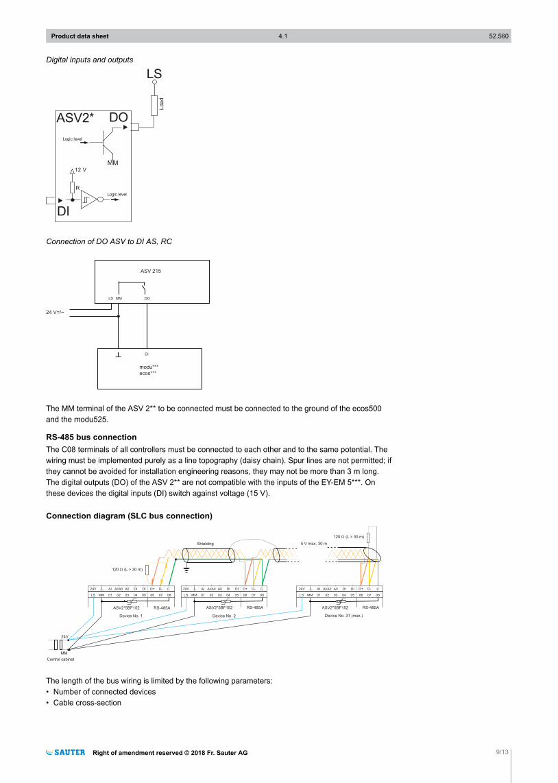
Digital inputs and outputs
DOASV2*
LS
Loa
d
Logic level
DI
12 V
RLogic level
MM
Connection of DO ASV to DI AS, RC
ASV 215
LS MM DO
24 V=/~
DI
modu***
ecos***
The MM terminal of the ASV 2** to be connected must be connected to the ground of the ecos500and the modu525.
RS-485 bus connectionThe C08 terminals of all controllers must be connected to each other and to the same potential. Thewiring must be implemented purely as a line topography (daisy chain). Spur lines are not permitted; ifthey cannot be avoided for installation engineering reasons, they may not be more than 3 m long.The digital outputs (DO) of the ASV 2** are not compatible with the inputs of the EY-EM 5***. Onthese devices the digital inputs (DI) switch against voltage (15 V).
Connection diagram (SLC bus connection)
24V 24VAI AI AIAI/A0 AI/A0 AI/A0DI DI DIA0 A0 A0D+ D+ D+D- D- D-DI DI DI
LS01 01 0102 02 0203 03 0304 04 0405 05 0506 06 0607 07 0708 08 08MM MM
ASV2*5BF152 ASV2*5BF152 ASV2*5BF152RS-485A RS-485A RS-485A
C
Device No. 31 (max.)
120 (L > 30 m)Ω
120 (L > 30 m)Ω
Shielding
Control cabinet
Device No. 1
MM
24V
Device No. 2
1.1A 1.1A
24V
LS MM LS
CC
1.1A1.1A
5 V max. 30 m
The length of the bus wiring is limited by the following parameters:• Number of connected devices• Cable cross-section
Product data sheet 4.1 52.560
Right of amendment reserved © 2018 Fr. Sauter AG 9/13
!CAUTION!Faulty wiring can result in damage to the device.
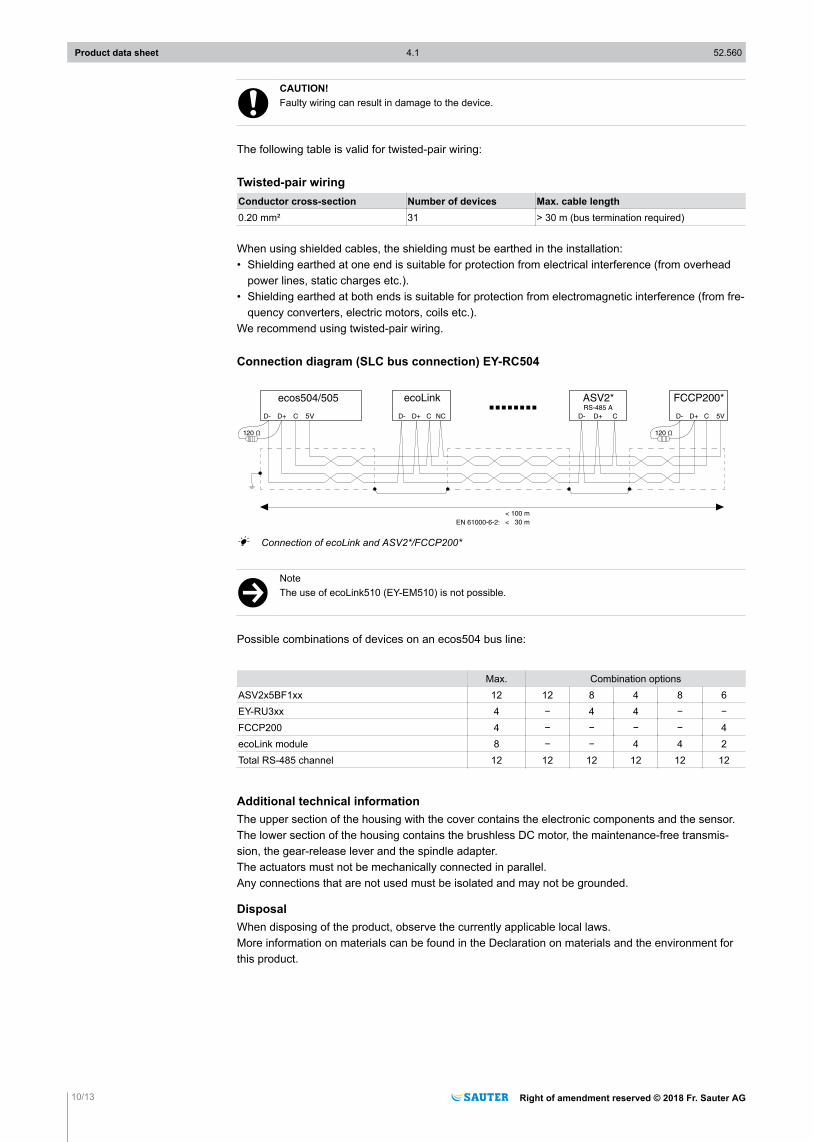
The following table is valid for twisted-pair wiring:
Twisted-pair wiringConductor cross-section Number of devices Max. cable length0.20 mm² 31 > 30 m (bus termination required)
When using shielded cables, the shielding must be earthed in the installation:• Shielding earthed at one end is suitable for protection from electrical interference (from overhead
power lines, static charges etc.).• Shielding earthed at both ends is suitable for protection from electromagnetic interference (from fre-
quency converters, electric motors, coils etc.).We recommend using twisted-pair wiring.
Connection diagram (SLC bus connection) EY-RC504
V
ecos504/505 ASV2*
< 30 mEN 61000-6-2:
< 100 m
ecoLink FCCP200*RS-485 A
5V
A Connection of ecoLink and ASV2*/FCCP200*
)NoteThe use of ecoLink510 (EY-EM510) is not possible.
Possible combinations of devices on an ecos504 bus line:
Max. Combination optionsASV2x5BF1xx 12 12 8 4 8 6EY-RU3xx 4 − 4 4 − −FCCP200 4 − − − − 4ecoLink module 8 − − 4 4 2Total RS-485 channel 12 12 12 12 12 12
Additional technical informationThe upper section of the housing with the cover contains the electronic components and the sensor.The lower section of the housing contains the brushless DC motor, the maintenance-free transmis-sion, the gear-release lever and the spindle adapter.The actuators must not be mechanically connected in parallel.Any connections that are not used must be isolated and may not be grounded.
DisposalWhen disposing of the product, observe the currently applicable local laws.More information on materials can be found in the Declaration on materials and the environment forthis product.
Product data sheet 4.1 52.560
10/13 Right of amendment reserved © 2018 Fr. Sauter AG
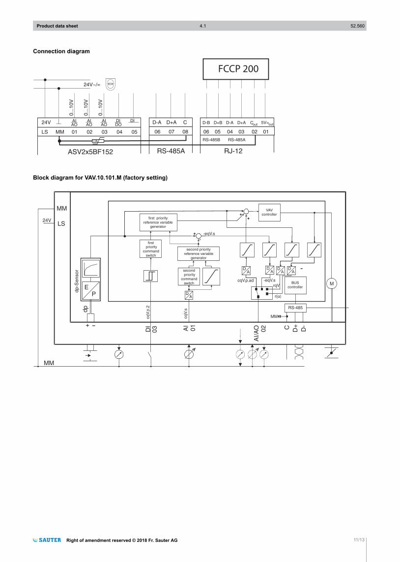
Connection diagram
RS-485A
D-A D+A C D-B D+B D-A D+A C 5V=
06 05 04 03 02 01
RJ-12
06 07 08
RS-485B RS-485A
outout
0..
.10
V
0..
.10
V
0..
.10
V
ASV2x5BF152
LS MM 01 05040302
24VAIAO
AIAO
AIAO
DIDO
DI
1.1A1.1A
FCCP 200
Block diagram for VAV.10.101.M (factory setting)
MM
PE
dp
firstpriority
commandswitch
M
dp-S
en
so
r
first priorityreference variable
generator
secondpriority
commandswitch
second priorityreference variable
generator
-
+
-eqV.s
cqV.s
++
cqV.p.ad -eqV.s
DA
DA
VAVcontroller
AI
01
AI/A
O 02
03DI
BUScontroller
RS-485
D+C D-
MM
LS24V
+
MM
DA
DA
rqV
r(α)
Product data sheet 4.1 52.560
Right of amendment reserved © 2018 Fr. Sauter AG 11/13
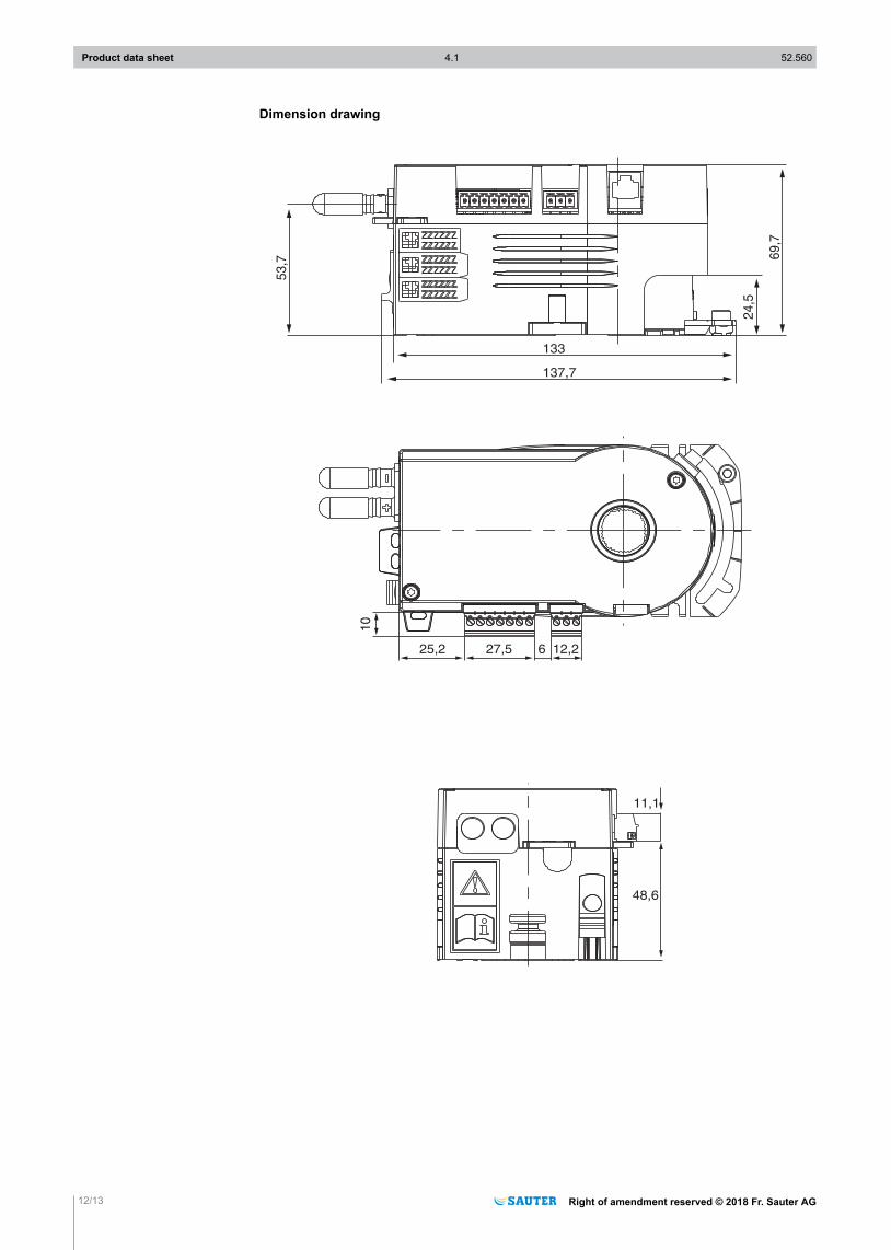
Dimension drawing
53,7 69
,7
10
25,2
48,6
11,1
27,5 6 12,2
24,5
137,7
133
Product data sheet 4.1 52.560
12/13 Right of amendment reserved © 2018 Fr. Sauter AG
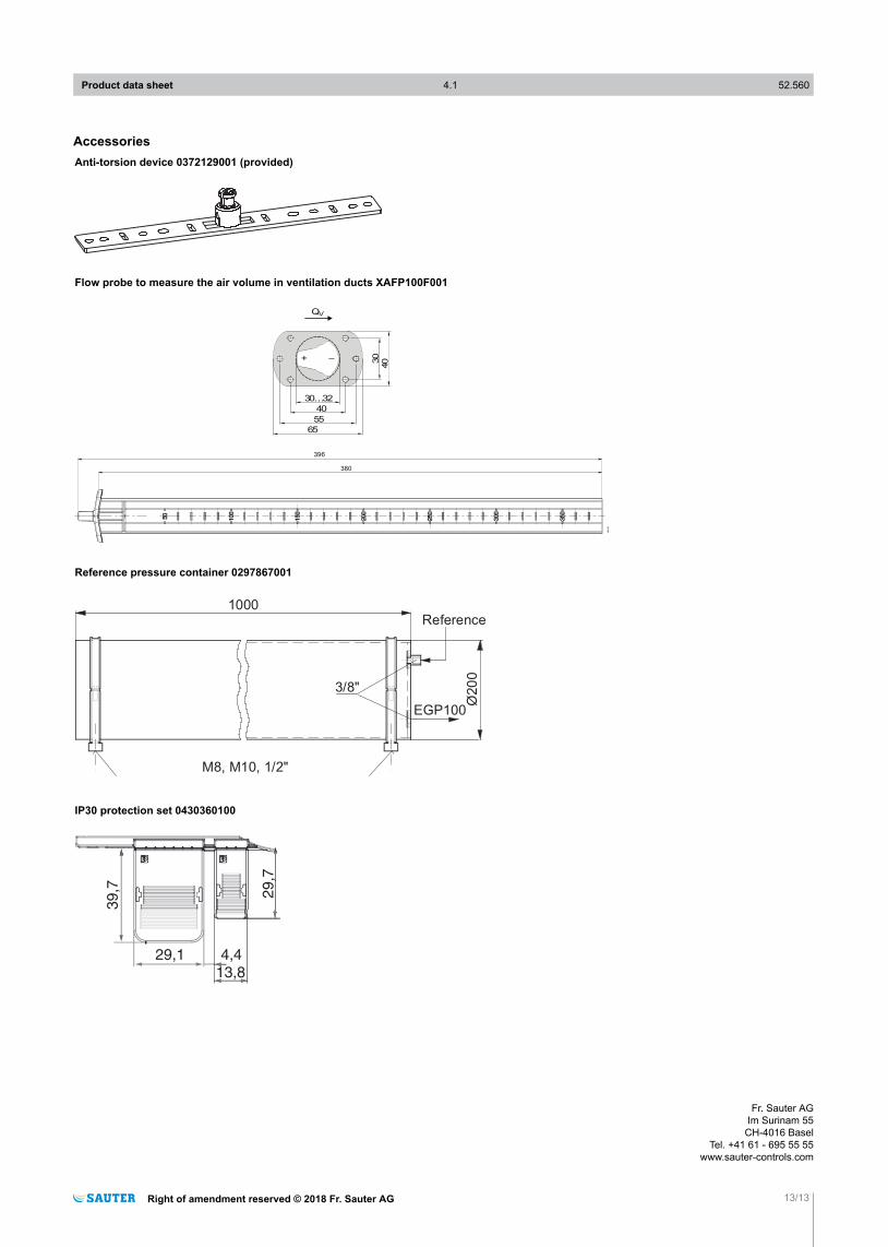
AccessoriesAnti-torsion device 0372129001 (provided)
Flow probe to measure the air volume in ventilation ducts XAFP100F001
M11433
30…32
40
55
30+ –
QV
396
380
65
40
Reference pressure container 0297867001
1000
Ø200
3/8"
M8, M10, 1/2"
Reference
EGP100
IP30 protection set 0430360100
39,7 29,7
29,1 4,4
13,8
Product data sheet 4.1 52.560
Right of amendment reserved © 2018 Fr. Sauter AG 13/13
Fr. Sauter AGIm Surinam 55
CH-4016 BaselTel. +41 61 - 695 55 55
www.sauter-controls.com