cost effective automation
TRANSCRIPT

COST EFFECTIVE AUTOMATIONREPORT 2017:435
SMARTA ELNÄT

Cost effective automation Open architecture for cost effective protection and
control of power distribution networks
GULNARA ZHABELOVA, CHEN-WEI YANG, LARS CHRISTOFFERSSON, VALERIY VYATKIN
ISBN 978-91-7673-435-3 | ©Energiforsk October 2017
Energiforsk AB | Phone: 08-677 25 30 | E-mail: [email protected] | www.energiforsk.se


COST EFFECTIVE AUTOMATION
3
Förord
Detta projekt behandlar fokusområdet Mer automation i eldistributionsnätet inom programmet Smarta Elnät. Projektet visar på möjligheten att med en exekveringsplattform utföra kontrollerade P&C-funktioner från olika leverantörer. Resultatet understöder leverantörsoberoende krav och utformning av stationsautomation, möjliggörande komplexa skyddssystem till lägre kostnad.
Projektet är ett samarbete mellan leverantörer, universitet och användare. Projektet kombinerar den senaste utvecklingen i kommunikation (IEC 61850) och industriella informatik (IEC 61499). Projektet syftar till att utveckla IEC 61499 skyddssystemet och testa den på 10 / 0,4 kV transformatorstation i en realtids laboratorium installation.
Huvudsökande är prof. Valeriy Vyatkin, Kommunikations – och beräkningssystem/ datavetensakap vid Luleå tekniska universitet. Gulnara Zhabelova från Luleå Tekniska Universitet har varit projektledare för projektet. Stort tack också till referensgruppen, som på ett mycket välförtjänt sätt har bidragit till projektet:
• Hakan Ünal, Göteborgenergi AB • Niklas Sigfridsson, Vattenfall • Ellevio, Joar Johansson • Erik Wejander, Svenska kraftnåt • Robert Saers, ABB • Matz Tapper, Svensk Energi • Hakan Ünal, Göterburg Energi • Jonas Sandberg, Luleå Energi
Programmets Smarta Elnät programstyrelse består av följande ledamöter:
• Peter Söderström, Vattenfall Eldistribution AB (ordförande) • Torbjörn Solver, Mälarenergi AB (vice ordförande) • Mira Rosengren Keijser, Svenska kraftnät • Patrik Björnström, Sveriges ingenjörer (Miljöfonden) • Fredrik Hartman, Ellevio AB • Claes Wedén, ABB AB • Ferruccio Vuinovich, Göteborg Energi AB • Daniel Köbi, Jämtkraft AB • Björn Ållebrand, Trafikverket • Anders Höglund, Öresundskraft AB • Johan Wennerholm, Umeå Energi Elnät AB • Peter Addicksson, HEM AB • Henric Johansson, Jönköping Energi AB • David Håkansson, Borås Elnät AB • Hannes Schmied, NCC AB • Matz Tapper, Svensk Energi (adjungerad)
Följande bolag har deltagit som intressenter till projektet. Energiforsk framför ett stort tack till samtliga företag för värdefulla insatser.
• Sveriges Ingenjörer, Miljöfonden • Vattenfall Eldistribution AB • Ellevio AB • Svenska Kraftnät • Göteborg Energi AB • Elinorr ekonomisk förening • Mälarenergi Elnät AB • Kraftringen Nät AB • Jämtkraft AB • Umeå Energi Elnät AB • Öresundskraft AB • Karlstads Elnät AB • Jönköping Energi Nät AB • Halmstad Energi & Miljö Nät AB • Falu Elnät AB • Borås Elnät AB • AB Borlänge Energi • C4 Elnät AB • Luleå Energi AB • ABB AB • Elsäkerhetsverket • Akademiska Hus • NKT Cables AB • NCC Construction Sverige AB • Trafikverket
Stockholm i januari 2017
Susanne Olausson Energiforsk AB Programområde Elnät, Vindkraft och Solel

COST EFFECTIVE AUTOMATION
5
Sammanfattning
Trenderna inom automation i eldistributionsnätet blir alltmer kundorienterade: 1) allt effektivare systemkonfiguration genom utnyttjande av gemensam hårdvaruplattform; 2) flexibla kombinationer av funktioner och utrustning; 3) kostnadseffektiv implementering av sofistikerade skyddssystem.
Projektet motiveras av att dagens teknik har potentialen att möjliggöra denna nya idé om automationssystem. Projektet undersöker i synnerhet möjligheter att 1) upphäva den starka kopplingen mellan hårdvara och mjukvara och 2) administrera systemets alla skyddsfunktioner centralt.
Tanken är att mjukvaruskyddet och kontrollfunktionerna skulle kunna tillhandahållas av olika leverantörer oberoende av hårdvaran. Hårdvaran utgör en deterministisk exekveringsplattform för sådana funktioner i realtid. Eftersom funktionerna är driftskompatibla och portabla skulle de kunna administreras centralt, vilket minskar arbetet med och kostnaderna för konfiguration, uppgraderingar och underhåll.
Eldistributörerna kan dra nytta av återanvändbarhet och gratis tilldelning av funktioner liksom av att stationerna får ökad funktionalitet och bättre kontroll och underhåll till en minskad kostnad.
Syftet med projektet är att testa den tekniska genomförbarheten genom att: 1) demonstrera användningen av öppna standarder och en öppen exekveringsplattform för utveckling av skyddsfunktioner; 2) testa sådana funktioners prestanda med avseende på acceptabla reaktionstider; 3) undersöka metoder för verifiering av sådana funktioner och fjärruppgradering.
Projektet har genomförts på Luleå tekniska universitet i samarbete med IETV AB. Projektet leds av prof. Valeriy Vyatkin.
Projektets huvudresultat är det IEC 61499-kompatibla skyddssystem som har utvecklats och testats; skyddsanordningens reaktionstid var 4 ms i genomsnitt. Projektet har levererat en rapport om metoder för verifiering och fjärruppgradering av IEC 61499-kompatibla automationssystem. Resultaten presenterades vid IEEE Smart Grid Communications Conference 2016 i Australien.
Detta projekt har i viss mening visat mod nog att testa en sådan här idés genomförbarhet och bärkraft. Genom att visa att konceptet är genomförbart har vi satt igång en diskussion inom referensgruppen av industriella partner om fördelar, teknisk tillförlitlighet och hot (juridiska frågor om ansvar för fel samt immateriella rättigheter) med avseende på mjukvaruskydd och kontrollsystem från flera leverantörer.
COST EFFECTIVE AUTOMATION
6
Summary
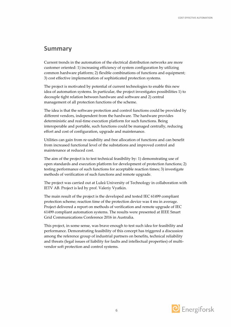
Current trends in the automation of the electrical distribution networks are more customer oriented: 1) increasing efficiency of system configuration by utilizing common hardware platform; 2) flexible combinations of functions and equipment; 3) cost effective implementation of sophisticated protection systems.
The project is motivated by potential of current technologies to enable this new idea of automation systems. In particular, the project investigates possibilities 1) to decouple tight relation between hardware and software and 2) central management of all protection functions of the scheme.
The idea is that the software protection and control functions could be provided by different vendors, independent from the hardware. The hardware provides deterministic and real-time execution platform for such functions. Being interoperable and portable, such functions could be managed centrally, reducing effort and cost of configuration, upgrade and maintenance.
Utilities can gain from re-usability and free allocation of functions and can benefit from increased functional level of the substations and improved control and maintenance at reduced cost.
The aim of the project is to test technical feasibility by: 1) demonstrating use of open standards and execution platform for development of protection functions; 2) testing performance of such functions for acceptable reaction times; 3) investigate methods of verification of such functions and remote upgrade.
The project was carried out at Luleå University of Technology in collaboration with IETV AB. Project is led by prof. Valeriy Vyatkin.
The main result of the project is the developed and tested IEC 61499 compliant protection scheme; reaction time of the protection device was 4 ms in average. Project delivered a report on methods of verification and remote upgrade of IEC 61499 compliant automation systems. The results were presented at IEEE Smart Grid Communications Conference 2016 in Australia.
This project, in some sense, was brave enough to test such idea for feasibility and performance. Demonstrating feasibility of this concept has triggered a discussion among the reference group of industrial partners on benefits, technical reliability and threats (legal issues of liability for faults and intellectual properties) of multi-vendor soft protection and control systems.
COST EFFECTIVE AUTOMATION
7
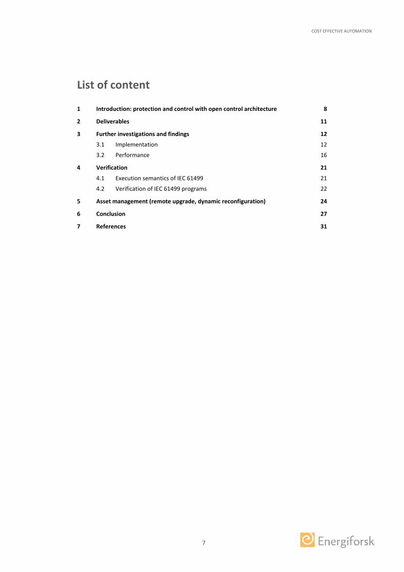
List of content
1 Introduction: protection and control with open control architecture 8 2 Deliverables 11 3 Further investigations and findings 12
3.1 Implementation 12 3.2 Performance 16
4 Verification 21 4.1 Execution semantics of IEC 61499 21 4.2 Verification of IEC 61499 programs 22
5 Asset management (remote upgrade, dynamic reconfiguration) 24 6 Conclusion 27 7 References 31
COST EFFECTIVE AUTOMATION
8
1 Introduction: protection and control with open control architecture
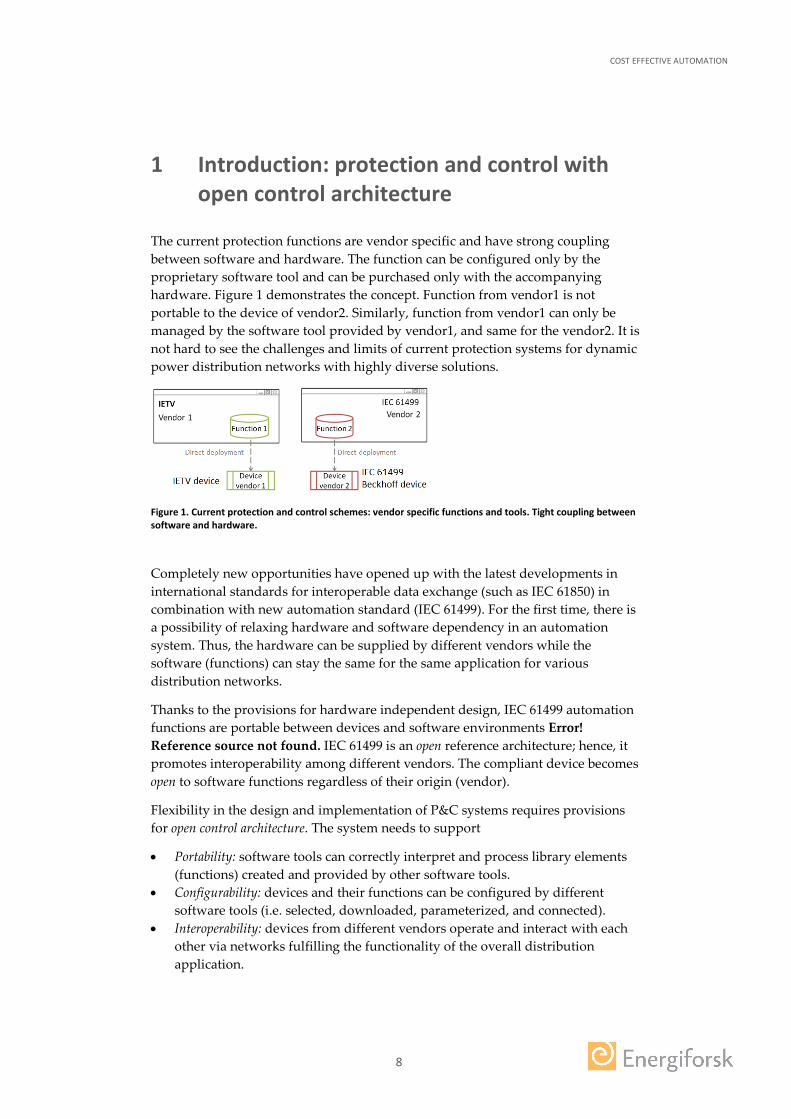
The current protection functions are vendor specific and have strong coupling between software and hardware. The function can be configured only by the proprietary software tool and can be purchased only with the accompanying hardware. Figure 1 demonstrates the concept. Function from vendor1 is not portable to the device of vendor2. Similarly, function from vendor1 can only be managed by the software tool provided by vendor1, and same for the vendor2. It is not hard to see the challenges and limits of current protection systems for dynamic power distribution networks with highly diverse solutions.
Figure 1. Current protection and control schemes: vendor specific functions and tools. Tight coupling between software and hardware.
Completely new opportunities have opened up with the latest developments in international standards for interoperable data exchange (such as IEC 61850) in combination with new automation standard (IEC 61499). For the first time, there is a possibility of relaxing hardware and software dependency in an automation system. Thus, the hardware can be supplied by different vendors while the software (functions) can stay the same for the same application for various distribution networks.
Thanks to the provisions for hardware independent design, IEC 61499 automation functions are portable between devices and software environments Error! Reference source not found. IEC 61499 is an open reference architecture; hence, it promotes interoperability among different vendors. The compliant device becomes open to software functions regardless of their origin (vendor).
Flexibility in the design and implementation of P&C systems requires provisions for open control architecture. The system needs to support
• Portability: software tools can correctly interpret and process library elements (functions) created and provided by other software tools.
• Configurability: devices and their functions can be configured by different software tools (i.e. selected, downloaded, parameterized, and connected).
• Interoperability: devices from different vendors operate and interact with each other via networks fulfilling the functionality of the overall distribution application.
COST EFFECTIVE AUTOMATION
9
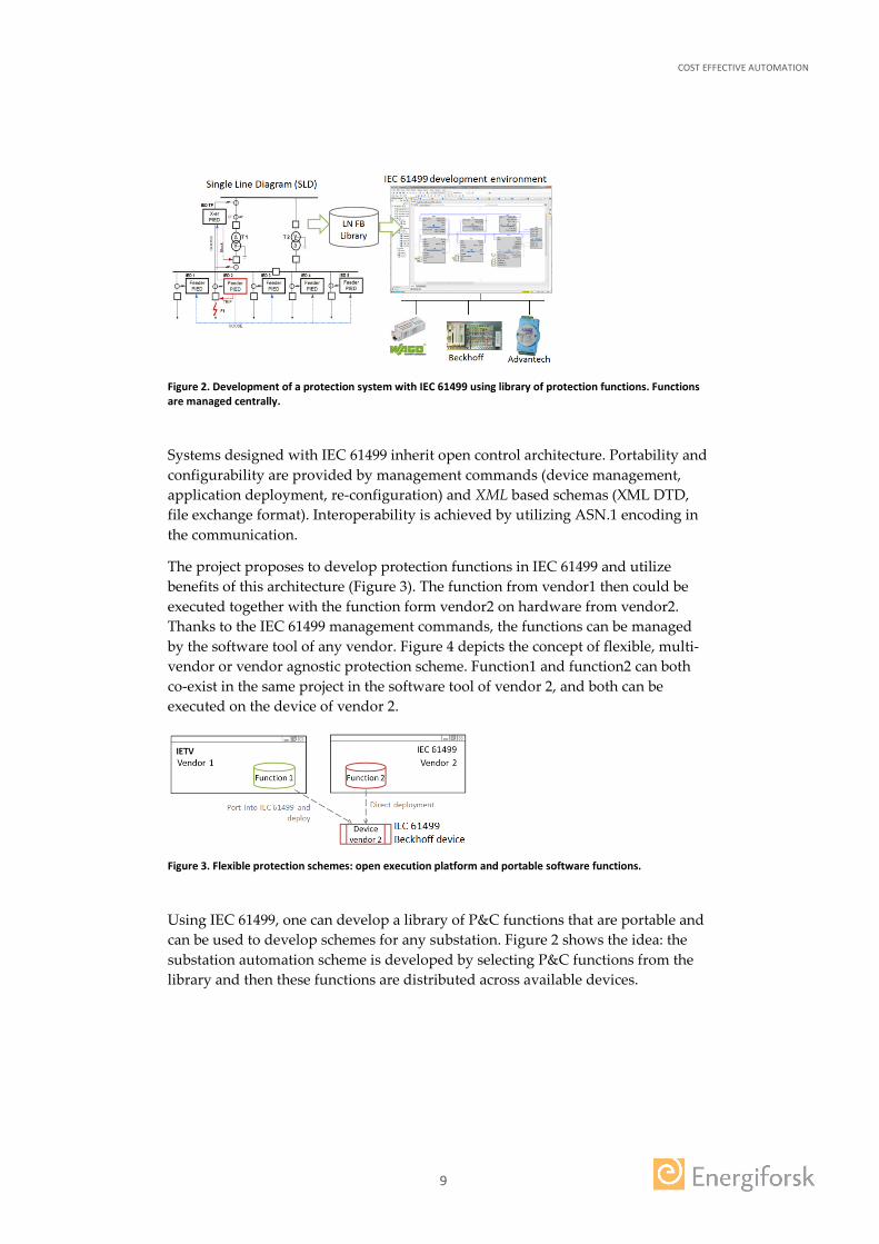
Figure 2. Development of a protection system with IEC 61499 using library of protection functions. Functions are managed centrally.
Systems designed with IEC 61499 inherit open control architecture. Portability and configurability are provided by management commands (device management, application deployment, re-configuration) and XML based schemas (XML DTD, file exchange format). Interoperability is achieved by utilizing ASN.1 encoding in the communication.
The project proposes to develop protection functions in IEC 61499 and utilize benefits of this architecture (Figure 3). The function from vendor1 then could be executed together with the function form vendor2 on hardware from vendor2. Thanks to the IEC 61499 management commands, the functions can be managed by the software tool of any vendor. Figure 4 depicts the concept of flexible, multi-vendor or vendor agnostic protection scheme. Function1 and function2 can both co-exist in the same project in the software tool of vendor 2, and both can be executed on the device of vendor 2.
Figure 3. Flexible protection schemes: open execution platform and portable software functions.
Using IEC 61499, one can develop a library of P&C functions that are portable and can be used to develop schemes for any substation. Figure 2 shows the idea: the substation automation scheme is developed by selecting P&C functions from the library and then these functions are distributed across available devices.
COST EFFECTIVE AUTOMATION
10
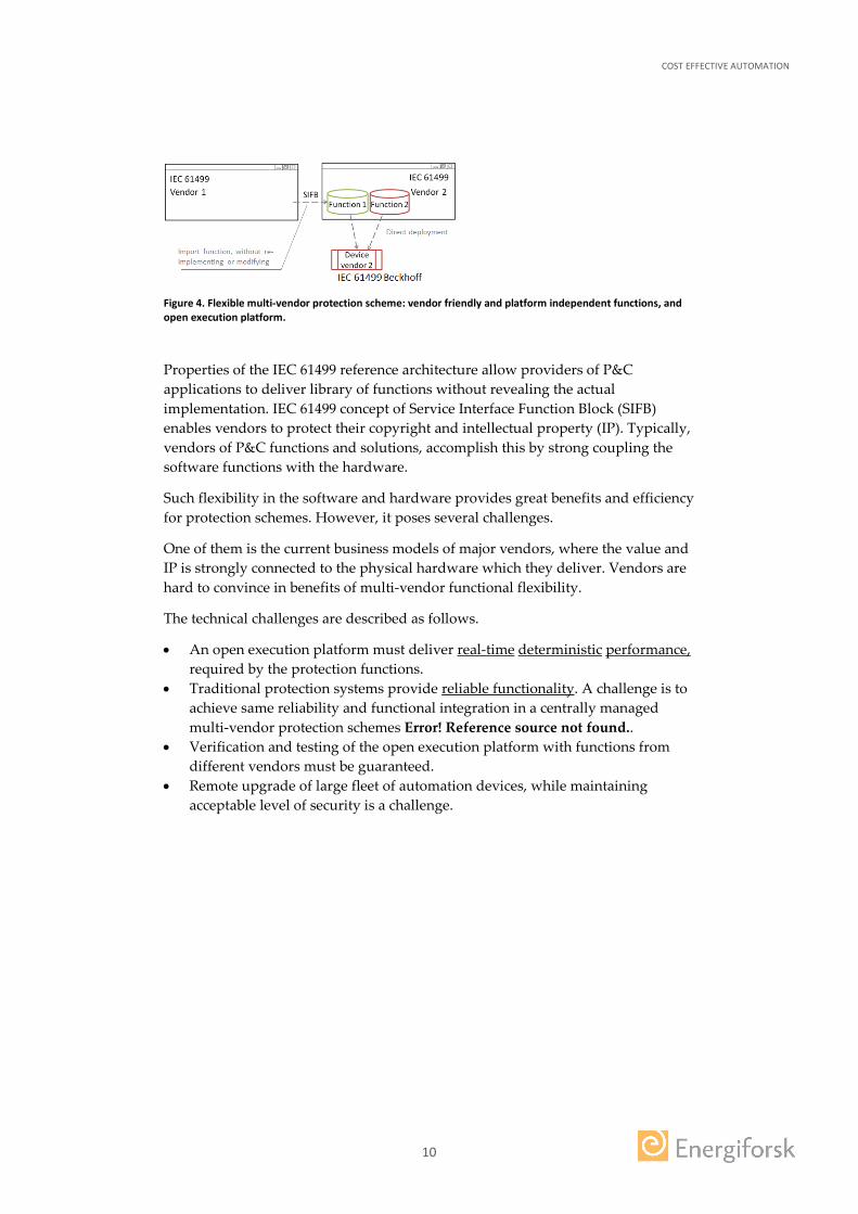
Figure 4. Flexible multi-vendor protection scheme: vendor friendly and platform independent functions, and open execution platform.
Properties of the IEC 61499 reference architecture allow providers of P&C applications to deliver library of functions without revealing the actual implementation. IEC 61499 concept of Service Interface Function Block (SIFB) enables vendors to protect their copyright and intellectual property (IP). Typically, vendors of P&C functions and solutions, accomplish this by strong coupling the software functions with the hardware.
Such flexibility in the software and hardware provides great benefits and efficiency for protection schemes. However, it poses several challenges.
One of them is the current business models of major vendors, where the value and IP is strongly connected to the physical hardware which they deliver. Vendors are hard to convince in benefits of multi-vendor functional flexibility.
The technical challenges are described as follows.
• An open execution platform must deliver real-time deterministic performance, required by the protection functions.
• Traditional protection systems provide reliable functionality. A challenge is to achieve same reliability and functional integration in a centrally managed multi-vendor protection schemes Error! Reference source not found..
• Verification and testing of the open execution platform with functions from different vendors must be guaranteed.
• Remote upgrade of large fleet of automation devices, while maintaining acceptable level of security is a challenge.

COST EFFECTIVE AUTOMATION
11
2 Deliverables
The scope of the project was 7 months, starting February to September 2016.
The deliverables of the projects are described below.
1. Use case: protection system for medium voltage Leivoll substation in Norway. 2. A model of the transformer section of the substation in Matlab Simulink
instead of OpalRT simulator. 3. Protection scheme developed for the use case, implemented in IEC 61499 in
nxtStudio. 4. Overcurrent protection function 5. Differential protection function 6. Earth protection function 7. Ported existing IEC 61131 overcurrent protection provided by IETV AB to IEC
61499 8. All functions above deployed to a single Beckhoff device. 9. Simulation of system integration. Online co-simulation of Matlab model with
IEC 61499 protection functions. 10. Performance testing with Omicron device and with the test set up at LTU
(section 4). 11. Results of 1-7 are documented in a report in a form of paper “Open
Architecture for cost effective Protection Control of Power Distribution Networks” [1]. The paper is submitted and accepted to Smart Grid Communication 2016 conference.
12. Initial findings on 1) methods of verification IEC 61499 protection functions and 2) remote upgrade in a system with open architecture.
The detailed description of 1-7 is described in the paper [1], that is also attached to the report.
The main findings of 9 are described below in the sections 5 and 6.
COST EFFECTIVE AUTOMATION
12
3 Further investigations and findings
3.1 IMPLEMENTATION
The detailed description of implementation and deliverables 1-7 is described in the paper [1].
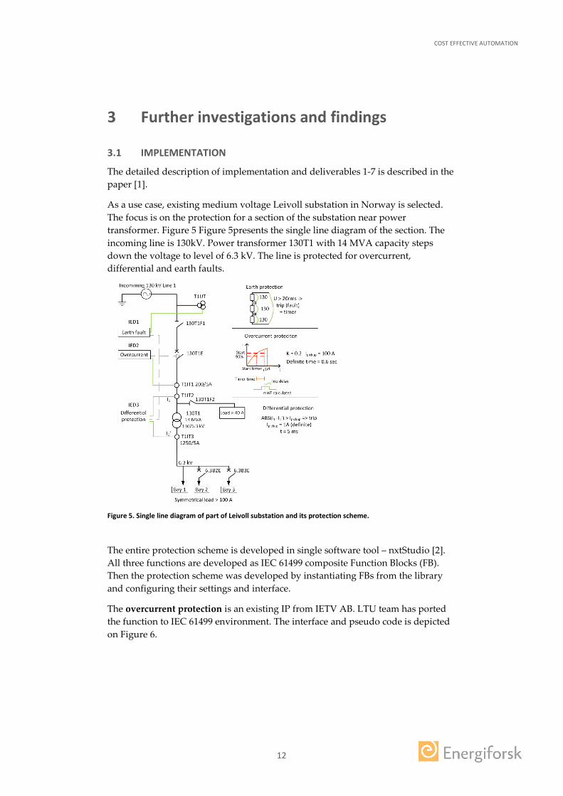
As a use case, existing medium voltage Leivoll substation in Norway is selected. The focus is on the protection for a section of the substation near power transformer. Figure 5 Figure 5presents the single line diagram of the section. The incoming line is 130kV. Power transformer 130T1 with 14 MVA capacity steps down the voltage to level of 6.3 kV. The line is protected for overcurrent, differential and earth faults.
Figure 5. Single line diagram of part of Leivoll substation and its protection scheme.
The entire protection scheme is developed in single software tool – nxtStudio [2]. All three functions are developed as IEC 61499 composite Function Blocks (FB). Then the protection scheme was developed by instantiating FBs from the library and configuring their settings and interface.
The overcurrent protection is an existing IP from IETV AB. LTU team has ported the function to IEC 61499 environment. The interface and pseudo code is depicted on Figure 6.

COST EFFECTIVE AUTOMATION
13
if MEASUREDCURRENT > ratedCurrent then FAULTDETECTED is true; end if FAULTDETECTED is true then case CURVETYPE do cType1: Calculate delayTime; cType2: Calculate delayTime; cType3: Calculate delayTime; cType4: Calculate delayTime; end end start TON_TIMER delayTime; if TON_TIMER expired then Send Tripping signal; end
Figure 6. Overcurrent protection function: interface and pseudo code.
The function is implemented in IEC 61131 ST language. Since IEC 61499 supports most of the PLC programming languages prescribed in IEC 61131-3, porting from IEC 61131 to IEC 61499 is relatively straightforward albeit with some challenges which are not major.
The earth protection function is depicted in Figure 7. Voltage readings are arrived to the FB with each REQ event. If the line-to-earth voltage exceeds highest rms value of 20, the FB sends trip signal out.
Figure 7. Earth protection function: interface and execution control chart.
COST EFFECTIVE AUTOMATION
14
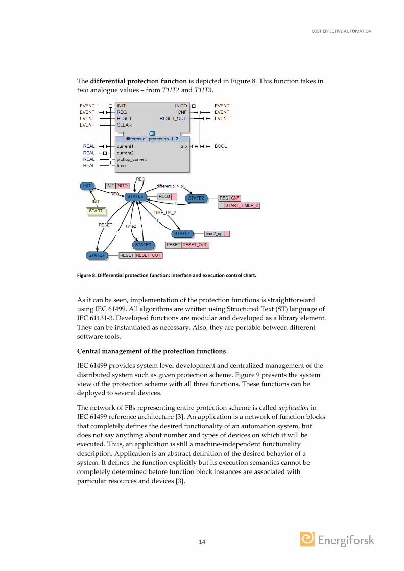
The differential protection function is depicted in Figure 8. This function takes in two analogue values – from T1IT2 and T1IT3.
Figure 8. Differential protection function: interface and execution control chart.
As it can be seen, implementation of the protection functions is straightforward using IEC 61499. All algorithms are written using Structured Text (ST) language of IEC 61131-3. Developed functions are modular and developed as a library element. They can be instantiated as necessary. Also, they are portable between different software tools.
Central management of the protection functions
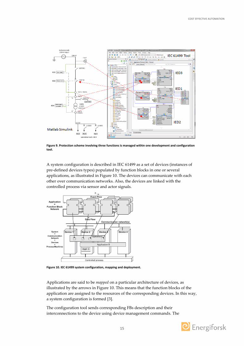
IEC 61499 provides system level development and centralized management of the distributed system such as given protection scheme. Figure 9 presents the system view of the protection scheme with all three functions. These functions can be deployed to several devices.
The network of FBs representing entire protection scheme is called application in IEC 61499 reference architecture [3]. An application is a network of function blocks that completely defines the desired functionality of an automation system, but does not say anything about number and types of devices on which it will be executed. Thus, an application is still a machine-independent functionality description. Application is an abstract definition of the desired behavior of a system. It defines the function explicitly but its execution semantics cannot be completely determined before function block instances are associated with particular resources and devices [3].
COST EFFECTIVE AUTOMATION
15
Figure 9. Protection scheme involving three functions is managed within one development and configuration tool.
A system configuration is described in IEC 61499 as a set of devices (instances of pre-defined devices types) populated by function blocks in one or several applications, as illustrated in Figure 10. The devices can communicate with each other over communication networks. Also, the devices are linked with the controlled process via sensor and actor signals.
Figure 10. IEC 61499 system configuration, mapping and deployment.
Applications are said to be mapped on a particular architecture of devices, as illustrated by the arrows in Figure 10. This means that the function blocks of the application are assigned to the resources of the corresponding devices. In this way, a system configuration is formed [3].
The configuration tool sends corresponding FBs description and their interconnections to the device using device management commands. The

COST EFFECTIVE AUTOMATION
16
application distribution is performed transparently in nxtStudio. The communication blocks are inserted by the tool in the places where FBs where separated to be mapped to different device [3].
IEC 61499 devices contain one resource manager - MGR. The central part of device management is the function block KERNEL, which communicates with a configuration tool and executes the received management commands. Management of devices is conducted by sending the device command messages from the configuration tool. The function block MGR receives the management commands in XML, and then it processes and executes them and replies to the command sender with confirmations or error messages. The IEC 61499 standard does not define the list of management commands. Nonetheless, a compliance profile was created for tentative use in feasibility demonstrations that contains a concise set of necessary management commands. These management commands are described in the section 6.
Thus, central management of protection functions is possible in IEC 61499. Moreover, it is possible with configuration tools from different vendors (compliant with IEC 61499 architecture).
3.2 PERFORMANCE
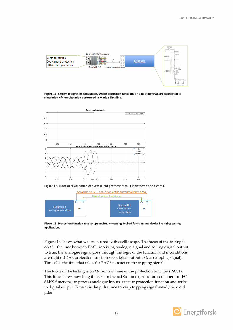
The protection scheme for the transformer section of the Leivoll substation is tested with the simulation of the system integration. The test setup is shown in the Figure 11 below. All three protection functions are deployed to Beckhoff programmable automation controller (PAC). Interface between Matlab model and Beckhoff PAC is via Ethernet network. Instrument transformers send current and voltage samples from Matlab to Beckhoff PAC via network. Tripping signals from Beckhoff PAC are sent to Matlab model to the corresponding circuit breaker. Details on this test are reported in paper [1]. Simulation validates that all three functions can co-exist in a controlled manner on same execution platform. Functional performance of protection scheme implemented in IEC 61499 is proved correct. In all three cases, faults were adequately detected and isolated. Figure 12 shows reaction of the overcurrent protection in system integration simulation.
Evaluation of the timing performance and its compliance to the industry standards are described next. Initially the functions were tested with Omicron device; the test uncovered inefficiency in the implementation of the functions. The functions were improved and another set of tests were carried out.
Figure 13 shows the test set up. Two Beckhoff PACs were used. Beckhoff PAC1 executes the protection function; Beckhoff PAC2 runs testing application. PAC2 generates analogue signals imitating the current/voltage samples from the instrumentation transformers. Reaction of the PAC1 is measured using oscilloscope that is attached to the IOs of PAC1
COST EFFECTIVE AUTOMATION
17
Figure 11. System integration simulation, where protection functions on a Beckhoff PAC are connected to simulation of the substation performed in Matlab Simulink.
Figure 12. Functional validation of overcurrent protection: fault is detected and cleared.
Figure 13. Protection function test setup: device1 executing desired function and device2 running testing application.
Figure 14 shows what was measured with oscilloscope. The focus of the testing is on t1 – the time between PAC1 receiving analogue signal and setting digital output to true; the analogue signal goes through the logic of the function and if conditions are right (<1.5A), protection function sets digital output to true (tripping signal). Time t2 is the time that takes for PAC2 to react on the tripping signal.
The focus of the testing is on t1- reaction time of the protection function (PAC1). This time shows how long it takes for the nxtRuntime (execution container for IEC 61499 functions) to process analogue inputs, execute protection function and write to digital output. Time t3 is the pulse time to keep tripping signal steady to avoid jitter.
COST EFFECTIVE AUTOMATION
18
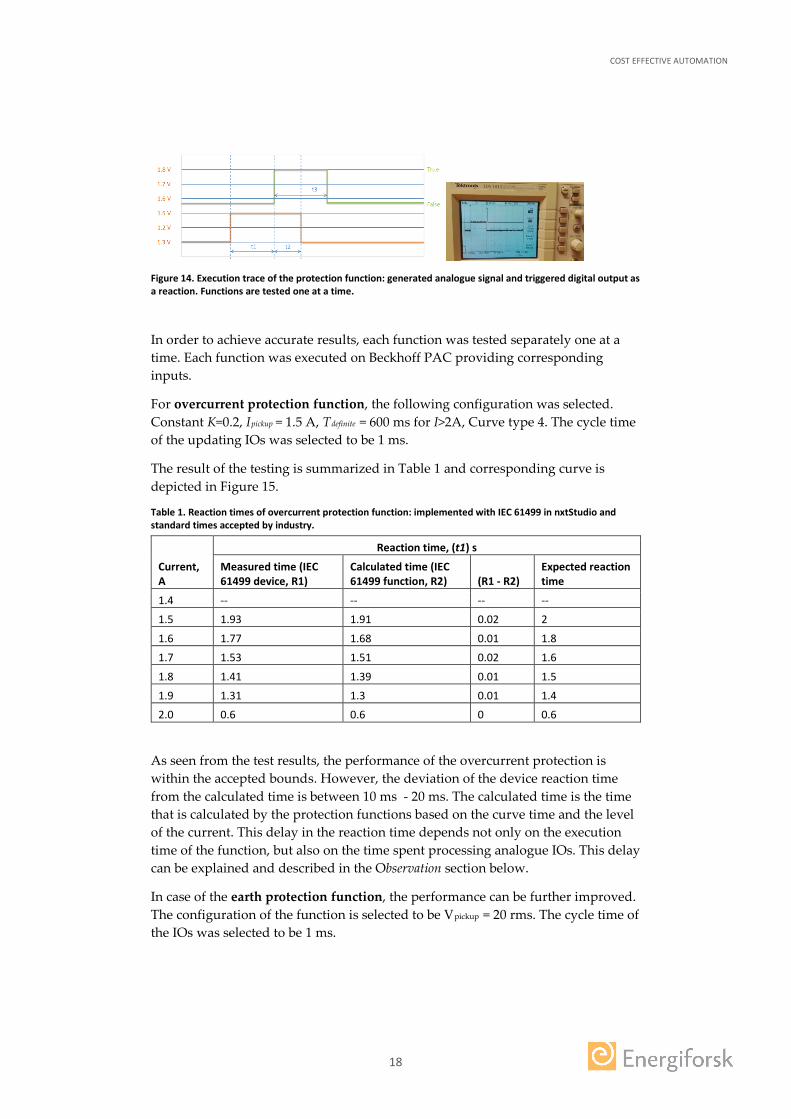
Figure 14. Execution trace of the protection function: generated analogue signal and triggered digital output as a reaction. Functions are tested one at a time.
In order to achieve accurate results, each function was tested separately one at a time. Each function was executed on Beckhoff PAC providing corresponding inputs.
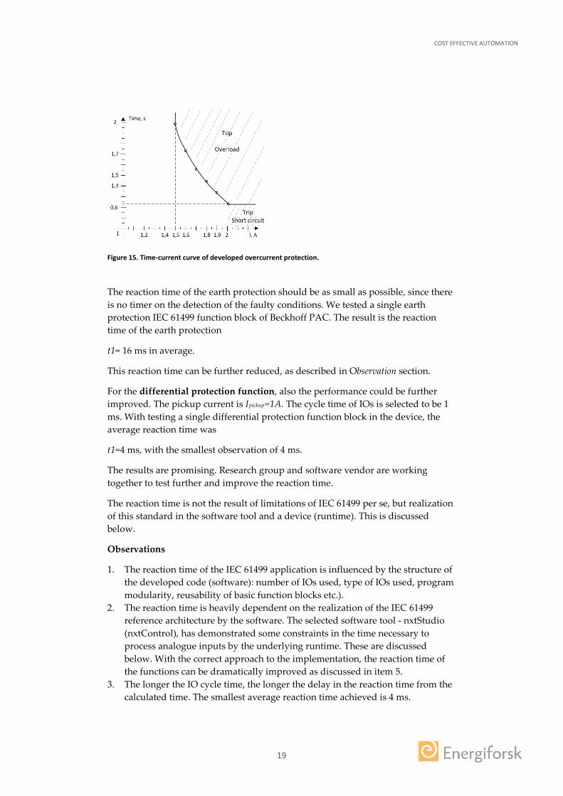
For overcurrent protection function, the following configuration was selected. Constant K=0.2, Ipickup = 1.5 A, Tdefinite = 600 ms for I>2A, Curve type 4. The cycle time of the updating IOs was selected to be 1 ms.
The result of the testing is summarized in Table 1 and corresponding curve is depicted in Figure 15.
Table 1. Reaction times of overcurrent protection function: implemented with IEC 61499 in nxtStudio and standard times accepted by industry.
Current, A
Reaction time, (t1) s
Measured time (IEC 61499 device, R1)
Calculated time (IEC 61499 function, R2) (R1 - R2)
Expected reaction time
1.4 -- -- -- --
1.5 1.93 1.91 0.02 2
1.6 1.77 1.68 0.01 1.8
1.7 1.53 1.51 0.02 1.6
1.8 1.41 1.39 0.01 1.5
1.9 1.31 1.3 0.01 1.4
2.0 0.6 0.6 0 0.6
As seen from the test results, the performance of the overcurrent protection is within the accepted bounds. However, the deviation of the device reaction time from the calculated time is between 10 ms - 20 ms. The calculated time is the time that is calculated by the protection functions based on the curve time and the level of the current. This delay in the reaction time depends not only on the execution time of the function, but also on the time spent processing analogue IOs. This delay can be explained and described in the Observation section below.
In case of the earth protection function, the performance can be further improved. The configuration of the function is selected to be Vpickup = 20 rms. The cycle time of the IOs was selected to be 1 ms.
COST EFFECTIVE AUTOMATION
19
Figure 15. Time-current curve of developed overcurrent protection.
The reaction time of the earth protection should be as small as possible, since there is no timer on the detection of the faulty conditions. We tested a single earth protection IEC 61499 function block of Beckhoff PAC. The result is the reaction time of the earth protection
t1= 16 ms in average.
This reaction time can be further reduced, as described in Observation section.
For the differential protection function, also the performance could be further improved. The pickup current is Ipickup=1A. The cycle time of IOs is selected to be 1 ms. With testing a single differential protection function block in the device, the average reaction time was
t1=4 ms, with the smallest observation of 4 ms.
The results are promising. Research group and software vendor are working together to test further and improve the reaction time.
The reaction time is not the result of limitations of IEC 61499 per se, but realization of this standard in the software tool and a device (runtime). This is discussed below.
Observations
1. The reaction time of the IEC 61499 application is influenced by the structure of the developed code (software): number of IOs used, type of IOs used, program modularity, reusability of basic function blocks etc.).
2. The reaction time is heavily dependent on the realization of the IEC 61499 reference architecture by the software. The selected software tool - nxtStudio (nxtControl), has demonstrated some constraints in the time necessary to process analogue inputs by the underlying runtime. These are discussed below. With the correct approach to the implementation, the reaction time of the functions can be dramatically improved as discussed in item 5.
3. The longer the IO cycle time, the longer the delay in the reaction time from the calculated time. The smallest average reaction time achieved is 4 ms.
COST EFFECTIVE AUTOMATION
20
4. There is clamp induced delay in the processing of IOs. Clamp delays of digital IOs are smaller than analogue IOs. So if take only digital IOa, the execution time of the device includes application delay + worst-case digital clamp delay + time needed for processing + time for the hardware clam itself. These all adds up to the device execution time of more than 3 cycle times. To guarantee cycle times less than 5 ms, the underlying operating system must be hard real time. This is not possible on a general purpose operating system. However, the clamp induced delays can be reduced. This is discussed in item 5.
5. The processing of the analogue values usually involves more work than processing of digital values, and therefore software might not process analogue values every cycle. Then the digital output is sent on the next bus cycle. This is consistent with our results. LTU is working together with the IEC 61499 tool vendor nxtControl towards improving performance of the functions implemented with nxtStudio and running on nxtRuntime on Beckhoff controller.
6. Another action that is panned is to test IEC 61499 protection functions on an alternative vendor – 4DIAC. This vendor has different method of accessing analogue IOs and execution semantics. This IEC 61499 implementation is adopted by NOJA Power LTD for their automatic recloser RC10.
COST EFFECTIVE AUTOMATION
21
4 Verification
Real time performance of the program is the ability of the execution semantics to meet real-time constraints. The real time performance in industrial automation systems largely depends on the capabilities of the hardware device.
Determinism is a property of the program, where given a set of initial states and a sequence of input values, it should be possible to accurately predict the system output after a specific time period and this could be repeated with the same outcome.
Both real-time properties and determinism of the software program depends on the execution semantics of the underlying programming paradigm. The real-time reaction also depends on the hardware as mentioned above.
IEC 61499 has several different realizations that resulted in several execution semantics, where same program will have slightly different behavior and properties.
Moreover, some of IEC 61499 realizations can be easier or harder to verify for deterministic behavior and can offer real-time performance of various degrees.
To estimate complexity, maintainability and testability of software, one needs to use well defined software metrics. Some initial work has been done on determining metrics for IEC 61499 software in [4].
In this project, protection functions were developed in nxtStudio software tool that is based on sequential execution semantics of IEC 61499.
4.1 EXECUTION SEMANTICS OF IEC 61499
The execution of events as prescribed by the IEC 61499 standard implies that only one function block can be active at every moment of time. This definition leaves room for interpretation which has led to two main execution models: sequential and cyclic [3].
The IEC 61499 integrated development environments (IDE) that follows the sequential execution model are NxtStudio and 4DIAC-IDE. The idea of sequential execution is that the sequence of emitted events is preserved and it is stored in a global event queue [3]. The order of execution of function blocks (FB) are based on this order of events, meaning once a FB has finished its single run, the next FB to be executed is the recipient of the emitted event in the top of the event queue.
Cyclic execution is based on the legacy PLC-based automation systems where function blocks are invoked periodically in a cyclic manner, regardless of the order of the emitted events [3]. This execution model is implemented in the ISaGRAF IDE and its motivation was to provide backward compatibility with legacy PLC system. The limitation of this approach is, at a single scan cycle, it is possible that more than one event inputs of a FB are energized. This is problematic since there is no way to determine the order of arrival of these energized events. This limitation can be mitigated by only invoking energized events from the previous scan cycle.
COST EFFECTIVE AUTOMATION
22
Parallel execution model is explored recently with the growing popularity of multi-core processors [3]. The idea of parallel execution is that several FBs can be executed at a given time provided that the concurrent FBs do not interfere during execution. This, of course, violates the provision that only one FB can be executed at a given time. However, this requirement was conceived on the notion of single-core processors. Parallel execution can provide fastest reaction time since FBs can run in parallel. One implementation of a synchronous parallel execution is presented in [5] with the notion of ticks which equates to one transition in an execution control chart (ECC) of a basic FB. Comparatively, an asynchronous parallel approach has also been proposed which assumes a tick equates to a single run of any FB.
Another realization of IEC 61499 that aims at achieving determinism is time-triggered discrete-event model [6]. This implementation retains the features of event-driven system, but the processing of events is based on time and priority. This implementation of IEC 61499 is of interest due to its promise in determinism. This approach is interesting and promising for implementation of deterministic programs and worth exploring for future work.
4.2 VERIFICATION OF IEC 61499 PROGRAMS
IEC 61499 is an open reference architecture for distributed industrial automation, and therefore programs developed with this architecture has to satisfy requirements for determinism and real-time performance. There is a large research community that investigates verification of the IEC 61499 programs. There are a number of verification and validation techniques.
Simulation is a method for validation. In a closed loop simulation, control and plant are simulated in parallel [7-10]. The controller is tested not only against known and expected inputs and events in the plant model, but also in the presence of plant dynamics. Plant dynamics can exhibit unexpected behavior as a response to the sequence of actions carried out by the controller. Therefore, the controller is tested in close to realistic settings, which is an advantage. The system can be validated with hardware in the loop (HiL), software in the loop (SiL); and sometimes with the communication system in the loop (either model or real) [1-9, 11, 12].
Formal methods are used for verification of the controller. Formal verification is a process to check whether program satisfy certain requirements. Both the system and the requirements (properties) are mathematically described, i.e. formally represented. Then the properties of the program could be mathematically proven. It is needed if one has to do more rigorous analysis and definite proof as compared to traditional manual empirical testing. Formal models are used in formal verification. Formal verification has been applied de-facto to any hardware design since the FDIV bug discovered in Intel chips [13]. Formal verification of software is challenging and been in the research domain for decades. It is applied in software, embedded systems, industrial automation and automotive industry. Model-checking is one such formal verification approach introduced in early 1980s by Clarke and Emerson [14].
Formal modeling of IEC 61499 has more than a decade long history [15, 16]. There are two basic approaches: 1) a direct representation of FB in a language supported
COST EFFECTIVE AUTOMATION
23
by a model-checking tool and 2) modeling of FB using an intermediate formal model and its subsequent translation to a language supported by a tool. So far there is no systematic approach to constructing models of FBs. In particular, there is no comprehensive pass-through formalization of FB models, that can reflect the system hierarchy, composite FB, algorithms and execution of FB models.
In contrast, using an intermediate formal model is a widely reported in literature: net condition/event systems (NCES) as the intermediate representation [17]; a method of modeling NCES in SMV [18]. The main drawbacks are limitations of model-checking tools, insufficient performance or limited support of arithmetic operations. From that perspective, the SMV approach promises some breakthroughs [19]. It should also be noted that the SMV system has been used quite successfully in the industry, e.g. in the verification of the function blocks of the IEC 61131-3 standard [20]. An automatic SMV model generation from IEC 61499 FB is used in [21, 22, 23].
COST EFFECTIVE AUTOMATION
24
5 Asset management (remote upgrade, dynamic reconfiguration)
There has been a growing trend to extend the accessibility of field devices remotely for commissioning and maintenance. This section provides a discussion on the potential of remote upgrade or reconfiguration of protection and control system compliant with IEC 61499.
IEC 61499 provides a framework for dynamic reconfiguration of automation systems which can be applied for the purpose of remote upgrade.
Dynamic reconfiguration is enabled by IEC 61499 management services which resides in the IEC 61499 control system in each control devices. Each “management service FB” has a standard interface according to the IEC 61499 compliance profile [24] and can be communicated to via the Ethernet communication protocol. Therefore, it is possible to remotely communicate with the field devices to reconfigure or update the existing controller application.
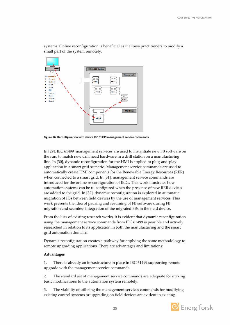
The framework for IEC 61499 management service is shown in Figure 16. On an IEC 61499 device, there can be several resources. In Figure 16, the main IEC 61499 control system resides in Resource 1 while the Management FB resides in the MGR Resource, awaiting management commands from a remote source. On a remote PC, a practitioner is able to issue standard management commands through a remote PC to the Management FB. The Management FB will process the incoming commands. For example, creating a new FB “TCTR2” in Figure 16. The standardized list of management services as prescribed by the IEC 61499 standard [25] are as follows:
1. CREATE: Creating a new FBType instance, data/event connections 2. DELETE: Deleting an existing FBType instance, data/event connections 3. START: Starting an FBType instance or application 4. STOP: Stopping an FBType instance or application 5. KILL: Stopping an FBType instance 6. QUERY: Querying various aspects of an application such as datatypes, FBType
instances and connections etc 7. READ: Reading parameter values 8. WRITE: Writing parameter values 9. RESET: Resetting FBType instances
This standardized list of management services allows practitioners to make modifications or reconfigure control systems remotely.
There is existing work in the research community which utilizes the management services to dynamically reconfigure automation systems. In [26, 27], IEC 61499 is used to overcome challenges of applying online changes for distributed automation systems in an effort to downtimeless reconfiguration. The proposed approach is to use synchronised clocks for remote configuration of automation systems using the management service commands. In [28], management services is used to dynamically reconfigure communication gateways in distributed embedded control
COST EFFECTIVE AUTOMATION
25
systems. Online reconfiguration is beneficial as it allows practitioners to modify a small part of the system remotely.
Figure 16. Reconfiguration with device IEC 61499 management service commands.
In [29], IEC 61499 management services are used to instantiate new FB software on the run, to match new drill head hardware in a drill station on a manufacturing line. In [30], dynamic reconfiguration for the HMI is applied to plug-and-play application in a smart grid scenario. Management service commands are used to automatically create HMI components for the Renewable Energy Resources (RER) when connected to a smart grid. In [31], management service commands are introduced for the online re-configuration of IEDs. This work illustrates how automation systems can be re-configured when the presence of new RER devices are added to the grid. In [32], dynamic reconfiguration is explored in automatic migration of FBs between field devices by the use of management services. This work presents the idea of pausing and resuming of FB software during FB migration and seamless integration of the migrated FBs in the field device.
From the lists of existing research works, it is evident that dynamic reconfiguration using the management service commands from IEC 61499 is possible and actively researched in relation to its application in both the manufacturing and the smart grid automation domains.
Dynamic reconfiguration creates a pathway for applying the same methodology to remote upgrading applications. There are advantages and limitations:
Advantages
1. There is already an infrastructure in place in IEC 61499 supporting remote upgrade with the management service commands.
2. The standard set of management service commands are adequate for making basic modifications to the automation system remotely.
3. The viability of utilizing the management services commands for modifying existing control systems or upgrading on field devices are evident in existing
COST EFFECTIVE AUTOMATION
26
research works for remote dynamic reconfiguration of IEC 61499 automation systems. The same methodology can be applied to remote upgrade IEC 61499 systems.
Limitations
1. It is not possible to modify the entire system at once. The components of the automation system such as the FBs, logical connections between the FBs etc. need to be instantiated individually. This invites the possibility of errors as the number of components which need to be dynamically instantiated increases. However, this limitation can be mitigated.
2. Only FB types which are already defined in the library of the field device can be instantiated.
Regarding the limitation of 2, there are attempts of overcoming this limitation by extending the existing set of the management service commands creating the possibility to dynamically create FBTypes via the management service commands [26]. This means it is possible to create new FB types and other aspects of an IEC 61499 system allowing greater flexibility in re-configuring and updating the existing IEC 61499 control system in the field devices.
COST EFFECTIVE AUTOMATION
27
6 Conclusion
The project was aimed at investigating technical feasibility of open execution platform where functions from different vendors can be managed centrally.
The idea is that the software protection and control functions could be provided by different vendors, independent from the hardware. The hardware provides deterministic and real-time execution platform for such functions. Being interoperable and portable, such functions could be managed centrally, reducing effort and cost of configuration, upgrade and maintenance.
This project was, in some sense, brave enough to test such idea for feasibility and performance. Although the project achieved good results proving the possibility of such protection and control systems, it has triggered many questions and concerns both in the technical reliability of such systems, legal issues of liability for faults and intellectual property.
The main results of the project are 1) developed and tested IEC 61499 compliant protection scheme; 2) paper published to IEEE Smart Grid Communications Conference; 3) discussion and findings on verification and remote upgrade of IEC 61499 compliant automation systems; 4) triggered a discussion in the participating industrial partners on possibility, feasibility, benefits, challenges and threats of multi-vendor soft protection and control systems.
Cost-effective and possible industrialization potential
Software cost is taking up an increasing portion of the automation systems in manufacturing and production. Similar trend is noticeable in substation protection and control. Software development, testing, maintenance, upgrade and configuration requires an increasing effort and contributes to increasing cost. Utilities have to manage substations with technologies from 30 years up to the present. During this time software has evolved into countless versions, supporting additional and new functions and platforms. Moreover, vendors have seized to exists, merged with others or discontinued the products. The cost of maintenance, configuration and upgrade of software is increasing.
Managing software is one part of the challenge. Problem of scaling and changing the power networks imposes many questions such as cost-efficiency, future proof and flexibility (among others). Considering technological changes, dynamics in the business of hardware/software vendors, utilities will benefit from flexible vendor-agnostic schemes. In the last decade cost of ruggedized hardware has been coming down, while providing increase in performance and communication capabilities. Now, opportunity has risen to test potential of such ideas.
The new “soft protection” or “multi-vendor” protection aim at reducing effort in configuration, increase functional flexibility, increase re-use of software and hardware, and in general increase digitalization level of substations.
Being interoperable and portable, such functions could be managed centrally, reducing effort and cost of configuration, upgrade and maintenance. To give an example, the flexibility of such schemes eases its engineering: easy to add/realize
COST EFFECTIVE AUTOMATION
28
new functionalities and special algorithms; simplified configuration and upgrade; possibility of free allocation of functions; possibility to run several functions on one hardware; possibility of central management of functions, even when deployed to different devices; easy to export data for further analysis and etc.
In this project, we demonstrated the use of IEC 61499 open reference architecture. As IEC 61499 software functions can be developed and deployed across multiple platforms, control engineers can finally obtain portability. Not only that the software functions can be developed within a single controller, but given freedom of function allocation and deployment an entire control and protection network can be developed. [34]
Utilities can gain from re-usability and free allocation of functions and can benefit from increased functional level of the substations and improved control and maintenance at reduced cost.
The possibility to buy equipment form different vendors leads to increased competition and market price.
Industrialization potential.
The presented idea of “cost effective automation” is based on technology that can provide portability, re-configurability and interoperability of the software functions. We proposed an approach that utilizes open standard to the development of software functions. This standard is IEC 61499. The interoperability can come with such protocols as IEC 61850, that provides standardized interface to IOs and protocol for fast and reliable communication.
IEC 61499 is gaining industrial recognition fast. There are several vendors that support IEC 61499 as part of their commercial product. To mention a few: nxtControl, Advantech, WAGO, tcs, and NOJA power.
NOJA power has launched the first commercial automatic recloser (RC10) that comes with IEC 61499 support [34]. Thanks to IEC 61499 compliance, RC10 is portable with other devices which supports the standard. Integration into complex control systems, substation design or PLC plant automation is now utterly conceivable.
“The level of portability and interoperability between multiple intelligent network devices unlocks a far greater scope of control and design capability for engineers in the field. With such a clearly defined standard, integration of IEC 61499 based automation is greatly simplified across complex networks of control” says NOJA Power Group Managing Director Neil O’Sullivan [34].
The available support and research into IEC 61499 both in academia and industry, promotes wide adoption of the technology [34].
In October 2016, within Horizon 2020 initiative, a European IEC 61499 Competence Center has been established [35] with partners from industry and universities. The Center has a mission of Technology Transfer from research to industry. “The Center is the aggregation point of the technologies need to deploy within the market an interoperable platform for cyber-physical systems” [35].

COST EFFECTIVE AUTOMATION
29
Compliance profile of IEC 61499 ensures portability and interoperability of the software functions. Such functions can be developed using tool from any vendor that supports IEC 61499. Then this function can be imported and added to any protection and control systems. The vendor can have full control of the code of the software, and can block the access to it protecting its intellectual property (IP). IEC 61499 has provisions for protecting IP.
IEC 61499 provide transparency in function allocation and deployment. It provides mechanisms that make it easy for an engineer to handle large distributed software applications, maintain and upgrade the software components.
There are several free tools (some are open source) that are available: 4DIAC, FBDK, Fbench and etc. NxtControl has free license tool that has only one limitation – will not allow to deploy to hardware (for that a license is required).
IEC 61499 has shown reasonable performance that is within the acceptable limits for protection system. IEC 61499 has well understood and studied execution models (as described in the report).
The challenges of the proposed idea are in provisions for flexibility, more specifically:
• determinism of the code for a particular hardware (when freely allocated); • performance of freely allocated functions on a hardware (reaction time);
These are well known challenges and are being heavily researched in real-time systems domain.
With the wider application and development and strong demand as it seen now, the concept of “soft protection” or “multi-vendor protection” has reasonable potential for industrial adoption. Interest shown by industrial partners, e.g. ABB, Vattenfall and IETV, demonstrates realistic vision and practicality of this approach. Moreover, with IEC 61499 and such protocols as IEC 61850, gaining momentum, and with support of large vendors e.g. NOJA power, the idea of flexible cost-effective automation systems is within the grasp.
Reference group comments
During the project reference group was formed for assessing projects results and giving directions. The group consisted from Svensk Energi, Ellevio, Svenska Kraftnät, ABB, Vattenfall, Göterborg Energi, Luleå Energi and IETV AB.
During reference group meeting the project triggered following comments.
• Legal issues of multi-vendor automation • Deterministic behavior: 1) How to trace whose fault it is in a open execution
platform where functions from different vendor are executed? 2) how to guarantee determinism of an open execution platform?
• Remote upgrade: 1) feasibility in a multi-vendor system? 2) how to test that function works remotely?
• How is the CPU load estimated beforehand in an arbitrary IE C61499 environment? How to predict performance of the open execution platform when executing new function from another vendor? We must know the

COST EFFECTIVE AUTOMATION
30
functions will not overload and hence delay or malfunction in the new HW environment.
• There is a possibility now to add inter-substation protection algorithms not possible before.
• In a system, capable of running multiple vendors' software in real time, would have to have generous performance/capacity margins and a very regimented set of services to ensure that functions were implemented in compatible and sociable ways.
• How to protect IP in a hardware independent way?
Next steps of the research
The comments of the reference group raise big research questions and motivate the future research. Below are the research directions in a near future.
1. Improve reaction time of the protection functions with nxtControl 2. Implement and test these functions in 4DIAC. 3. Test these functions with NOJA SGA software and their recloser that is
compliant with IEC 61499. With three IEC 61499 compliant software tools provided by three different vendors (nxtControl, 4DIAC, NOJA SGA), test the concept where functions can be directly imported to the different tools without exposing their implementation (IP).
4. Continue work on verification of deterministic behavior and real-time performance of the IEC 16499 application. Also, work on methods to trace the execution of each FB to facilitate determinism in multi-vendor open execution platform.
5. Work on the use case to handle complete scope of substation automation: both protection functions from one vendor and control functions for a breaker from another vendor in a substation automation environment.
COST EFFECTIVE AUTOMATION
31
7 References
[1]. G. Zhabelova, C.W. Yang, V. Vyatkin, N. Etherden, L. Christofersson, ” Open Architecture for cost effective Protection Control of Power Distribution Networks”, IEEE Smart Grid Communications Conference 2016, Sydney, Australia.
[2]. nxtControl GmbH, nxtStudio Engineering tool, www.nxtcontrol.com [3]. V. Vyatkin, “IEC 61499 Function Blocks for Embedded And Distributed
Control Systems Design”, Third Edition, Instrumentation Society of America, Third Edition, 2014
[4]. G. Zhabelova and V. Vyatkin, "Towards software metrics for evaluating quality of IEC 61499 automation software," 2015 IEEE 20th Conference on Emerging Technologies & Factory Automation (ETFA), Luxembourg, 2015, pp. 1-8.
[5]. L. Yoong, P. Roop, V. Vyatkin, Z. Salcic, A synchronous Approach for IEC 61499 Function Block Implementation, IEEE Transactions on Computers, Vol 58, Issue 12
[6]. W. Dai, V. Vyatkin, C, Pang, J. H. Christensen, Time-stamped event based execution semantics for industrial cyber-physical systems, 13th IEEE International Conference on Industrial Informatics (INDIN 2015)
[7]. S. Preuse, H. Lapp, and H. Hanisch, "Closed-loop system modeling, validation, and verification," in Emerging Technologies & Factory Automation (ETFA), 2012 IEEE 17th Conference on, 2012, pp. 1-8.
[8]. M. Gevers, B. Codrons, and F. De Bruyne, "Model validation in closed loop," in American Control Conference, 1999. Proceedings of the 1999, 1999, pp. 326-330.
[9]. A. K. Mok and D. Stuart, "Simulation vs. verification: Getting the best of both worlds," in Computer Assurance, 1996. COMPASS'96, Systems Integrity. Software Safety. Process Security. Proceedings of the Eleventh Annual Conference on, 1996, pp. 12-22.
[10]. C.-h. Yang, G. Zhabelova, C.-W. Yang, and V. Vyatkin, "Cosimulation environment for event-driven distributed controls of smart grid," Industrial Informatics, IEEE Transactions on, vol. 9, pp. 1423-1435, 2013.
[11]. E. M. Clarke, M. Khaira, and X. Zhao, "Word level model checking-Avoiding the Pentium FDIV Error," in Design Automation Conference Proceedings 1996, 33rd, 1996, pp. 645-648.
[12]. E. M. Clarke, O. Grumberg, and D. A. Peled, Model Checking. Cambridge: The MIT Press, 1999.
[13]. H.-M. Hanisch, M. Hirsch, D. Missal, S. Preuße, and C. Gerber, "One Decade of IEC 61499 Modeling and Verification-Results and Open Issues," in 13th IFAC Symposium on Information Control Problems in Manufacturing, V.A. Trapeznikov Institute of Control Sciences, Russia, 2009.
COST EFFECTIVE AUTOMATION
32
[14]. M. Bonfe and C. Fantuzzi, "Design and verification of mechatronic object-oriented models for industrial control systems," in ETFA '03, IEEE Conference on Emerging Technologies and Factory Automation, 2003, pp. 253-260 vol.2.
[15]. S. Patil, S. Bhadra, and V. Vyatkin, "Closed-loop formal verification framework with non-determinism, configurable by meta-modelling," in IECON 2011 - 37th Annual Conference on IEEE Industrial Electronics Society, 2011, pp. 3770-3775.
[16]. V. Dubinin, H. M. Hanisch, V. Vyatkin, and S. Shestakov, "Analysis of extended net condition/event systems on the basis of model checking," presented at the Proc. Int. Conf. New Information Technologies and Systems (Originally published in Russian), Penza, 2010.
[17]. S. Patil, V. Dubinin, C. Pang, and V. Vyatkin, "Neutralizing Semantic Ambiguities of Function Block Architecture by Modeling with ASM," in Perspectives of System Informatics. vol. 8974, A. Voronkov and I. Virbitskaite, Eds., ed: Springer Berlin Heidelberg, 2015, pp. 76-91.
[18]. G. Frey and L. Litz, "Formal methods in PLC programming," in Systems, Man, and Cybernetics, 2000 IEEE International Conference on, 2000, pp. 2431-2436 vol.4.
[19]. S. Patil, V. Dubinin, and V. Vyatkin, "Formal Verification of IEC61499 Function Blocks with Abstract State Machines and SMV - Execution Semantics," in Symposium on Dependable Software Engineering, Nanjing, China, 2015.
[20]. S. Patil, V. Dubinin, and V. Vyatkin, "Formal Verification of IEC61499 Function Blocks with Abstract State Machines and SMV - Modelling," in The 13th IEEE International Symposium on Parallel and Distributed Processing with Applications (IEEE ISPA-15), Helsinki, Finland, 2015.
[21]. "Function blocks — Part 1: Architecture, IEC Standard 61499-1," Second ed, 2012.
[22]. D. Drozdov. (2015). FB2SMV: IEC 61499 Function blocks XML code to SMV converter. Available: https://github.com/dmitrydrozdov/fb2smv
[23]. S. Patil, G. Zahabelova, V. Vyatkin, and B. McMillin, "Towards Formal Verification of Smart Grid Distributed Intelligence: FREEDM case," in Industrial Electronics Society, IECON 2015 - 41st Annual Conference of the IEEE, Yokohama, Japan, 2015
[24]. J. H. Christensen, IEC 61499 Compliance Profile for Feasibility Demonstrations, Jan. 2006, [online] Available: http://www.holobloc.com/doc/ita/index.htm.
[25]. IEC 61499-4: Function Blocks – Part 4: Rules for compliance profiles, 2013 [26]. T. Strasser, C. Sunder, A. Zoitl, M. N. Rooker and J. E. J. Brunnenkreef,
"Enhanced IEC 61499 Device Management Execution and Usage for Downtimeless Reconfiguration," 2007 5th IEEE International Conference on Industrial Informatics, Vienna, 2007, pp. 1163-1168.
[27]. A. Schimmel, A. Zoitl, Distributed Online Changes for IEC 61499, 16th IEEE Conference on Emerging Technologies & Factory Automation (ETFA 2011)
COST EFFECTIVE AUTOMATION
33
[28]. F. Andren, T. Strasser, A. Zoitl, I. Hegny, A reconfigurable communication gateway for distributed embedded control systems, 38th Annual Conference on IEEE Industrial Electronics Society (IECON 2012)
[29]. G. Stambolov, I. Batchkova, Reconfiguration Processes in Manufacturing Systems on the Base of IEC 61499 Standard, The 6th IEEE International conference on Intelligent Data Acquisition and Advanced Computing Systems (IDAACS 2011)
[30]. C-W. Yang, J. Yan, V. Vyatkin, Towards implementation of Plug-and-Play and distributed HMI for the FREEDM system with IEC 61499, The 39th Annual conference of the IEEE Industrial Electronics Society (IECON 2013)
[31]. T. Strasser, F. Andren, F. Lehfuss, M. Stifter, P. Palensky, Online Reconfigurable Control Software for IEDs, IEEE Transactions on Industrial Informatics, Vol9, No 3
[32]. J. Yan, V. Vyatkin, Extension of reconfigurability provisions in IEC 61499, The 18th Conference on Emerging Technologies & Factory Automation (ETFA 2013)
[33]. V. Vyatkin, Software Engineering in Industrial Automation: State of the Art Review�, IEEE Transactions on Industrial Informatics, 9(4), 2013
[34]. V. Vyatkin, IEC 61499 as Enabler of Distributed and Intelligent Automation: State of the Art Review�, IEEE Transactions on Industrial Informatics, 7(4), 2011, pp. 768-781
[35]. NOJA POWER, “Automation Unconstrained: Absolute Control. AN Exploration into Distributed IEC 61499 Algorithms in Recloser Controller”, April 2017. http://www.nojapower.com.au/press/2017/exploration-into-distributed-IEC61499-algorithms-recloser-controllers.html?utm_source=press&utm_medium=em&utm_content=c&utm_campaign=pr_12_37_au
[36]. IEC 61499 European competence center http://www.synesis-consortium.eu/competence-center/
COST EFFECTIVE AUTOMATION The main result of the project is demonstration of protection scheme with open control architecture. Functions overcurrent, earth and differential were developed using IEC 61499 open reference architecture to demonstrate feasi-bility of these functions to be portable and configurable. Developed functions were managed from the single configuration tool using management com-mands. Thanks to IEC 61499 hardware abstraction, the scheme was developed in platform independent way. These three functions can be deployed to a single device or to three devices (one functions per device). The devices should be compliant with IEC 61499. The project tested performance of protection func-tions developed with IEC 61499 and executed on Beckhoff device.
This result demonstrated the possibility of 1) decoupling software and hard- ware; 2) free allocation of functions to any hardware; 3) central management of the functions; 4) vendor interoperability, portability and configurability of the protection scheme.
Utilities can gain from re-usability and free allocation of functions and can benefit from increased functional level of the substations and improved control and maintenance at reduced cost.
However, deterministic behavior and real-time execution of such systems with open architecture is still an open question and is the next step of this research.
Energiforsk is the Swedish Energy Research Centre – an industrially owned body dedicated to meeting the common energy challenges faced by industries, authorities and society. Our vision is to be hub of Swedish energy research and our mission is to make the world of energy smarter!