damic at snolab - fermilablss.fnal.gov/archive/2014/pub/fermilab-pub-14-382-a.pdf · damic at...
TRANSCRIPT

DAMIC at SNOLAB
Alvaro E. Chavarriaa, Javier Tiffenbergb, Alexis Aguilar-Arevaloc, Dan Amideid, Xavier Bertoue, Gustavo Cancelob,Juan Carlos D’Olivoc, Juan Estradab, Guillermo Fernandez Moronib, Federico Izraelevitchb, Ben Kilminsterf,
Yashmanth Langisettyd, Junhui Liaof, Jorge Molinag, Paolo Priviteraa, Carolina Salazarc, Youssef Sarkisc,Vic Scarpineb, Tom Schwarzd, Miguel Sofo Haroe, Frederic Trillaudc, Jing Zhoua
aKavli Institute for Cosmological Physics and The Enrico Fermi Institute, The University of Chicago, Chicago, IL, United StatesbFermi National Accelerator Laboratory, Batavia, IL, United StatescUniversidad Nacional Autonoma de Mexico, Mexico D.F., Mexico
dUniversity of Michigan, Ann Arbor, MI, United StateseCNEA/CONICET, Centro Atomico Bariloche, San Carlos de Bariloche, Argentina
fUniversity of Zurich, Zurich, SwitzerlandgFacultad de Ingenieria, Universidad Nacional de Asuncion (FIUNA), Asuncion, Paraguay
Abstract
We introduce the fully-depleted charge-coupled device (CCD) as a particle detector. We demonstrate its low energythreshold operation, capable of detecting ionizing energy depositions in a single pixel down to 50 eVee. We presentresults of energy calibrations from 0.3 keVee to 60 keVee, showing that the CCD is a fully active detector with uni-form energy response throughout the silicon target, good resolution (Fano ∼0.16), and remarkable linear response toelectron energy depositions. We show the capability of the CCD to localize the depth of particle interactions withinthe silicon target. We discuss the mode of operation and unique imaging capabilities of the CCD, and how they maybe exploited to characterize and suppress backgrounds. We present the first results from the deployment of 250 µmthick CCDs in SNOLAB, a prototype for the upcoming DAMIC100. DAMIC100 will have a target mass of 0.1 kgand should be able to directly test the CDMS-Si signal within a year of operation.
Keywords: DAMIC, Dark matter direct detection, Low-mass WIMPs, Low-threshold detectors, Charge-coupleddevices
1. DAMIC: Dark Matter in CCDs
There is strong cosmological and astrophysical evidence supporting the existence of non-baryonic, cold dark mat-ter as a major constituent of the Universe [1, 2]. Theoretical models propose the existence of weakly-interactingmassive particles (WIMP) with masses in the range 1–15 GeV/c2 as a possible explanation for dark matter [3]. Sta-tistically significant laboratory evidence for the detection of signals originating from scattering of WIMPs in lightnuclear targets have been reported [4, 5].
The goal of the DAMIC experiment is to use the bulk silicon of a scientific-grade charge-coupled device (CCD)as the target for coherent WIMP-nucleus elastic scattering. The relatively low mass of the silicon nucleus, as well asthe low read-out noise of the detector, make the CCD an ideal instrument for the identification of the nuclear recoilswith keV-scale energies from WIMPs with masses <10 GeV/c2. Historically, CCDs had not been considered as aviable WIMP detector due to their relatively low mass (1 g per detector). Yet, recent advances in CCD technology,mostly due to the increase in the purity of the silicon, allow for the fabrication of 1–5 g fully-depleted CCDs withexceptionally low levels of radioactive contamination. These instruments have been successfully characterized anddeployed in astronomy experiments [6], where their large area and thickness allow for the efficient detection of near-infrared light from astronomical objects.
The first WIMP search with a CCD as a WIMP target was performed at the MINOS near-site in Fermilab, yieldingthe best exclusion limits at the time for WIMPs with masses below 4 GeV/c2 [7]. In November, 2012 the DAMICcollaboration deployed six 1 g CCDs in the J-Drift hall of the SNOLAB laboratory in Canada. The vacuum vessel forthis setup and the shielding were designed to house up to 1 kg of silicon detectors. A subsequent deployment of two
Preprint submitted to Elsevier July 2, 2014
arX
iv:1
407.
0347
v1 [
phys
ics.
ins-
det]
30
Jun
2014

Buriedp channel
3-phaseCCD structure
Poly gateelectrodes
n— —(10 kΩ-cm)
Photo-sensitivevolume
(200_300µm)
Transparentrear window
Biasvoltage
xy
Figure 1. Cross-sectional diagram of the CCD described in this work.
2. FULLY-DEPLETED CCD PHYSICS AND OPERATION
Figure 1 shows a cross-sectional diagram of the fully-depleted, back-illuminated CCD. A conventionally-processed,three-phase CCD is fabricated on a high-resistivity, n-type silicon substrate. We have fabricated CCD’s on both100 mm and 150 mm diameter high-resistivity silicon substrates. The resistivity of 100 mm wafers is as high as10,000–12,000 -cm, while the initial work on 150 mm wafers has been on 4,000–8,000 -cm silicon.
The thickness of the CCD results in improved near-infrared sensitivity when compared to conventional thinnedCCD’s.1 This is due to the strong dependence of absorption length on wavelength at photon energies approachingthe silicon bandgap.4 Figure 2 shows measured quantum eciency (QE) versus wavelength for a fully-depleted,back-illuminated CCD operated at 130C. The QE is especially high at near-infrared wavelengths. The CCDshown in Figure 2 has a two-layer anti-reflection (AR) coating tuned for good red response. It consists of 60 nmof indium tin oxide (ITO) and 100 nm of silicon dioxide (SiO2).
Thick, fully-depleted CCD’s also greatly reduce the problem of “fringing” at near-infrared wavelengths.5
Fringing occurs when the absorption depth of the incident light exceeds the CCD thickness. Multiple reflectionsresult in fringing patterns that are especially a problem in 10–20 µm thick CCD’s used in spectrographs.
A unique feature of the CCD shown in Figure 1 is the use of a substrate bias to fully deplete the substrate.For a thick CCD fabricated on high-resistivity silicon the channel potential is to first order independent of thesubstrate bias.1 This is because for typical substrate thicknesses and doping densities considered here onlya small fraction of the electric field lines from the depleted channel terminate in the fully-depleted substrate.Hence the vertical clock levels can be set to optimize operating features such as well capacity and CTE whilethe substrate bias is used to deplete the substrate.
The substrate bias also plays a role in the point-spread function of the CCD. For light absorbed near theback surface of the CCD the lateral charge spreading during transit of the photogenerated charges through thefully-depleted substrate to the CCD collection wells is described by an rms standard deviation given by1, 6
od s
2kT
q
yD2
(Vsub VJ )(1)
where k is Boltzmann’s constant, T is absolute temperature, q is the electron charge, yD is the thickness ofthe depleted substrate, Vsub is the applied substrate bias voltage, and VJ is an average potential near theCCD potential wells due to the channel potentials. Vsub VJ is the voltage drop across the region wherethe photogenerated holes are drifted by the electric field. This result is a simplified asymptotic form that isindependent of the substrate doping and is valid for high electric fields in the substrate. Therefore in this casethe PSF is directly proportional to yD,
pT , and 1/
p(Vsub VJ ). The PSF for a CCD of this type can be
improved by reducing the substrate thickness and operating the CCD at high substrate bias. PSF measurementsare described in more detail in Section 5.
z
(a) A CCD pixel
z
x
y
(b) WIMP detection principle
Figure 1: a) Cross-sectional diagram of a 15 µm× 15 µm pixel in a fully depleted, back-illuminated charge-coupled device (CCD) [8]. The thicknessof the gate structure and the backside ohmic contact are ∼0.1µm. As used for DECam, the transparent rear window includes an anti-reflectivecoating of induim-tin-oxide (ITO), which contains the undesirable radioactive isotope 115In. b) Depiction of the WIMP detection principle, wherethe scattering of a DM particle with a Si nucleus leads to ionization being produced in the bulk silicon. The charge carriers are then drifted alongthe z direction and collected at the CCD gates.
z
pixe
l
x
x
y
σσ
100s ofμm
15 μm
Figure 2: Depiction of a point-like particle interaction within the CCD bulk. The charge is drifted along the z axis and it diffuses as it travels towardthe gates. This leads to a spatial distribution of the charge on the x-y plane whose variance (σ2) is proportional to the charge transit time. Fromthis lateral spread it is possible to reconstruct the depth of the interaction. A characteristic value for the charge spread in a DECam CCD from thebackside (250 µm deep) is σ ∼ 7 µm.
upgraded CCDs was performed in June, 2013 to address an unexpected source of uranium background in the CCDsupport. A further deployment of a setup with three new CCDs, expected to achieve radioactive background levelscomparable to those necessary for a WIMP search to test the CDMS-Si signal [4], will take place in February, 2014.The full deployment of DAMIC100 at SNOLAB, consisting of eighteen 5.5 g CCDs, is scheduled for Summer, 2014.
2. Overview of a DAMIC CCD
The DAMIC CCDs were designed and fabricated at Lawrence Berkeley National Laboratory MicroSystems Labfor the Dark Energy Survey (DES) camera (DECam) [8]. They feature a three-phase polysilicon gate structure witha buried p-channel. The pixel size is 15 µm× 15 µm and the active region of the detector is high-resistivity (10–20kΩ cm) n-type silicon with hundreds of µm thickness. The high-resistivity of the silicon allows for a low donordensity in the substrate (∼1011 cm−3), which leads to fully depleted operation at reasonably low values of the appliedbias voltage (∼20 V). The CCDs are typically 8 or 16 Mpixels, with surface areas of tens of cm2. Fig. 1 shows across-sectional diagram of the a CCD pixel, together with a sketch depicting the WIMP detection principle.
When operated at full depletion, ionization produced in the active region will be drifted along the direction of theelectric field (z axis). The holes (charge carriers) will be collected and held near the p-n junction, less than a µm below
2

120-120 0 240 360 480 600Energy / eV
-200 0 200 400 600 800 1000
1
10
210
310
410
510
Pixel values in low threshold image
Energy / eV-200 0 200 400 600 800 1000
1
10
210
310
410
510
Pixel values in low threshold image
Gaussian fit:9 eV RMS noise
Pixels with collected charge
(a) Distribution of pixel values
41804190
42004210
42201280
1290
1300
1310
1320
1330
5 10 15 20 25 30image
Energy measured by pixel / keV30252015105
4180 4190 4200 4210 42201280
1290
1300
1310
1320
1330
5
10
15
20
25
30image
α
e
μ
X-ray?n, WIMP?
Diffusionlimited
50 p
ixel
s
Front
Back
(b) Segment of a DAMIC image
Figure 3: a) Histogram of all the pixel values in an image after the median pixel value over many images has been subtracted. The readout noiseis the Gaussian distribution centered at zero, while the right-hand side tail corresponds to pixels where charge has been collected. The spike atzero is due to the image processing procedure, as every image is expected to contain some pixels whose value is the median over a set of images.b) 50×50 pixel segment of a DAMIC image when exposed to a 252Cf source on the surface. Only pixels with deposited energy >0.1 keVee arecolored. Clusters from different types of particles may be observed. Low energy electrons and nuclear recoils, whose physical track length is<15 µm, produce “diffusion limited” clusters, where the spatial extension of the cluster is dominated by charge diffusion (Fig. 2). Higher energyelectrons (e), from either Compton scattering or β decay, lead to extended tracks. α particles in the bulk or from the back of the CCD produce largeround structures due to the plasma effect [9]. Cosmic muons (µ) pierce through the CCD, leaving a straight track. The orientation of the track isimmediately evident from its width, the end-point of the track that is on the back of the CCD is much wider than the end-point at the front due tocharge diffusion.
the gates. The electrons are drained from the backside. Due to the mobility of the charge carriers, the ionized chargewill diffuse as it is drifted, with a spatial variance that is proportional to the carrier transit time. Charge produced byinteractions closer to the back of the CCD will have longer transit times, leading to greater lateral diffusion. From thelateral spread of the charge recorded on the CCD x-y plane, we can reconstruct the z position of the charge deposit.This is depicted in Fig. 2.
3. Energy threshold
In DAMIC, the CCD is operated by applying the substrate bias across the active region and collecting the ionizedcharge over a few hours. Then readout is performed, where the charge is shifted row-by-row and the signal extractedthrough the serial register on one side of the CCD. As the capacitance of the output sense node of the CCD is verysmall, it is possible to measure only a few electrons of charge collected at the gates. The data stream is digitized andthe pixel charge is measured. The read out rate is ∼1 Mpixel per minute. The RMS noise in each pixel measurement is∼2.5 e− (Fig. 3(a)). Considering that the average energy to create an electron-hole pair in Si is 3.62 eV, this correspondsto 9 eV. From the measured pixel values an image is constructed, containing all ionization energy deposits within theCCD over the exposure time (Fig. 3(b)).
The number of dark electrons (i.e. those produced by thermal excitations in the Si substrate) collected in eachpixel, which introduce Poissonian noise on its value, is proportional to the exposure time. For a 250 µm DAMIC CCDrunning at 133 K the dark current is typically ∼1 e−/pix/day. The exposure length of a DAMIC image is a few hours,therefore readout noise is the dominant source of noise.
As every image contains millions of pixels, to positively identify a pixel that has collected any charge, the conditionthat a pixel value is 5–6σ above the noise level is required. This sets the nominal DAMIC threshold at ∼50 eVee. The
3
Energy / keV0 1 2 3 4 5 6 7
1
10
210
310
Fe source from back55Spectrum from
63 eV RMSat 5.9 keV
Al K
Mn Kα Mn Kβ
Mn K escape lines
(a) Spectrum from a 55Fe source
2.11.81.51.20.90.60.30Energy measured by pixel / keV
1.7 keV
4.2 keV
pe from Mn Kα X-ray absorption
pe from Si fluorescence X-ray absorption
(b) Observation of a escape event
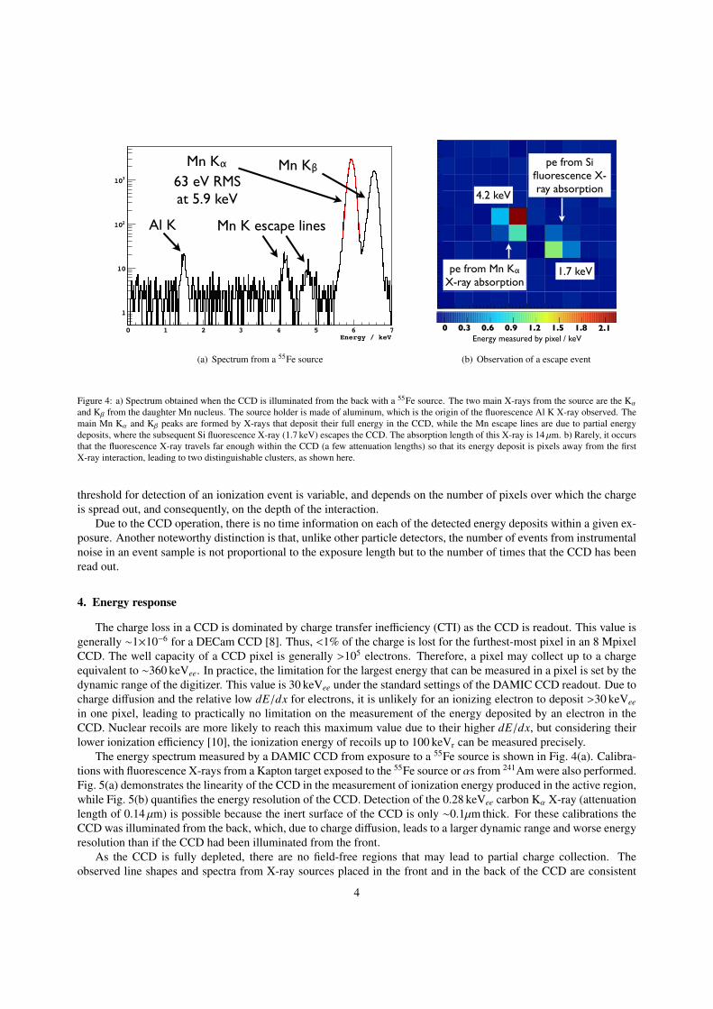
Figure 4: a) Spectrum obtained when the CCD is illuminated from the back with a 55Fe source. The two main X-rays from the source are the Kα
and Kβ from the daughter Mn nucleus. The source holder is made of aluminum, which is the origin of the fluorescence Al K X-ray observed. Themain Mn Kα and Kβ peaks are formed by X-rays that deposit their full energy in the CCD, while the Mn escape lines are due to partial energydeposits, where the subsequent Si fluorescence X-ray (1.7 keV) escapes the CCD. The absorption length of this X-ray is 14 µm. b) Rarely, it occursthat the fluorescence X-ray travels far enough within the CCD (a few attenuation lengths) so that its energy deposit is pixels away from the firstX-ray interaction, leading to two distinguishable clusters, as shown here.
threshold for detection of an ionization event is variable, and depends on the number of pixels over which the chargeis spread out, and consequently, on the depth of the interaction.
Due to the CCD operation, there is no time information on each of the detected energy deposits within a given ex-posure. Another noteworthy distinction is that, unlike other particle detectors, the number of events from instrumentalnoise in an event sample is not proportional to the exposure length but to the number of times that the CCD has beenread out.
4. Energy response
The charge loss in a CCD is dominated by charge transfer inefficiency (CTI) as the CCD is readout. This value isgenerally ∼1×10⁻⁶ for a DECam CCD [8]. Thus, <1% of the charge is lost for the furthest-most pixel in an 8 MpixelCCD. The well capacity of a CCD pixel is generally >105 electrons. Therefore, a pixel may collect up to a chargeequivalent to ∼360 keVee. In practice, the limitation for the largest energy that can be measured in a pixel is set by thedynamic range of the digitizer. This value is 30 keVee under the standard settings of the DAMIC CCD readout. Due tocharge diffusion and the relative low dE/dx for electrons, it is unlikely for an ionizing electron to deposit >30 keVee
in one pixel, leading to practically no limitation on the measurement of the energy deposited by an electron in theCCD. Nuclear recoils are more likely to reach this maximum value due to their higher dE/dx, but considering theirlower ionization efficiency [10], the ionization energy of recoils up to 100 keVr can be measured precisely.
The energy spectrum measured by a DAMIC CCD from exposure to a 55Fe source is shown in Fig. 4(a). Calibra-tions with fluorescence X-rays from a Kapton target exposed to the 55Fe source or αs from 241Am were also performed.Fig. 5(a) demonstrates the linearity of the CCD in the measurement of ionization energy produced in the active region,while Fig. 5(b) quantifies the energy resolution of the CCD. Detection of the 0.28 keVee carbon Kα X-ray (attenuationlength of 0.14 µm) is possible because the inert surface of the CCD is only ∼0.1µm thick. For these calibrations theCCD was illuminated from the back, which, due to charge diffusion, leads to a larger dynamic range and worse energyresolution than if the CCD had been illuminated from the front.
As the CCD is fully depleted, there are no field-free regions that may lead to partial charge collection. Theobserved line shapes and spectra from X-ray sources placed in the front and in the back of the CCD are consistent
4

Energy / keV1 10
Reconstructed energy / keV
1
10
Calibration data to X-ray lines
C Kα
O Kα
Al Kα
Si Kα
Ca Kα
55Fe
241Am
60 keV
(a) Linearity of the ionization energy scale
Energy / keV1 10
2Var(E) / keV
-310
-210
Energy resolution (back illumination)
var(E) = 0.16 x 3.62 eV x E
RMS = 30 eV (from noise)
(b) Energy resolution
Figure 5: a) Reconstructed energy of an X-ray line compared to its true energy. The labeled Kα markers are fluorescence lines from elements in theKapton target and other materials in the CCD setup. The 55Fe and 241Am markers are X-rays emitted by the radioactive sources. Linearity in themeasurement of ionization energy is demonstrated from 0.3 keVee to 60 keVee. b) Variance of the X-ray lines as a function of energy. The effectiveFano factor is 0.16, larger than the accepted value in Si of 0.1, but typical for a CCD [11]. As the illumination is from the backside, the charge isspread over many pixels. Thus, the readout noise added over many pixels leads to a limiting resolution of 30 eVee.
with the absence of any population of events with a significant loss of collected charge.It is well known that the ionization efficiency of nuclear recoils is significantly different than that of electrons.
Previous measurements have been done down to energies of 3–4 keVr [10, 12], yielding results in agreement withLinhard theory [13]. From this, DAMIC’s nominal 50 eVee threshold corresponds to ∼0.5 keVr. Given the significantuncertainty in the extrapolation, and the importance of precise nuclear recoil scale calibration for dark matter searches,we are planning a series of experiments to measure this value down to the threshold (Section 10).
5. Position reconstruction
Due to the pixelated nature of the CCD, the best estimate for the x and y coordinates of a point-like interactionmay be readily obtained from the charge-weighted mean of the x and y coordinates of pixels with collected charge. Inthe worst case, where the entire charge is collected in one pixel, the resolution in the values of the x and y coordinatesis 4.3 µm. For clusters where the charge is distributed over many pixels the resolution gets better, to .1 µm. Theobservation of escape events within the CCD (Fig. 4(b)) is a demonstration of its capability to resolve energy deposits10s of µm apart.
As discussed in Section 2, the spatial spread (σ) in a diffusion limited cluster may be used to reconstruct the depth(z coordinate) within the active region where the energy deposit took place. To estimate the best value for σ, weperform a likelihood fit to all the pixels within a four pixel radius of the pixel in the cluster with the largest value.We assume a Gaussian distribution in two dimensions, with σ and the mean values of x and y as free parameters.We consider the readout noise on every pixel when doing the fit. To test the performance of this procedure, wehave constructed a corresponding simulation, where events are generated on the true CCD readout noise pattern andfollowing the hypothesized Gaussian spatial distribution of the collected charge. The simulated value for σ is basedon the depth of the interaction (obtained from an independent MCNP particle physics simulation) assuming a simplemodel for the electric field in a fully depleted CCD [8]. The field magnitude has been tuned so that the maximumobserved diffusion matches that from a particular CCD deployed in SNOLAB. Fig. 6 presents the σ reconstructionresults for the Mn Kα X-ray. Fig. 7 shows the best-fit σ distributions as a function of energy for calibration data withlow energy X-rays impinging on the back of the CCD, and for events from a 252Cf source, which are expected to beuniformly distributed in the bulk.
5

σBest-fit 0 0.1 0.2 0.3 0.4 0.5 0.60
0.02
0.04
0.06
0.08
0.1
0.12
0.14
0.16
0.18
0.2
0.22
0.24
Fe55 distributions from σ
Front (data)
Front (simulation)
Back (data)
Back (simulation)
(a) Spatial σ distribution for Mn Kα
mµSimulated z / 0 50 100 150 200 250
σBest-fit
0
0.1
0.2
0.3
0.4
0.5
0.6
1
10
210
Fe simulation55
(b) Spatial σ vs. interaction depth (z) for Mn Kα
Figure 6: a) Best-fit σ (in pixels) distribution for Mn Kα (5.9 keV) X-rays for the cases where a 55Fe source is placed in the front (red) and inthe back (black) of a DAMIC CCD. The solid lines represent calibration data acquired at Fermilab, while the dashed lines are the results from thesimulation. The simulation was tuned to a different CCD deployed at SNOLAB, therefore the mismatch between the distributions is partly dueto performance variations between CCDs. The overall shape of the distributions is well reproduced by the simulation. b) Relationship betweenthe best-fit σ and the interaction depth. σ was obtained by performing the fit on simulated clusters, where the simulated σ was computed fromthe interaction depth (z). The interaction depth was obtained from a MCNP particle physics simulation of a 55Fe source on a Si target with theCCD geometry. The expected positive correlation between σ and z is recovered. Clusters on the back of the CCD may be easily identified as σ isobtained reliably. For cases where the charge is spread over very few pixels, σ cannot be precisely measured, leading to worsening determinationof σ at small values of z.
Reconstructed E / keV0 0.2 0.4 0.6 0.8 1 1.2 1.4 1.6 1.8 2
σBest-fit
0
0.1
0.2
0.3
0.4
0.5
0.6
0.7
0.8
0.9
1
1
10
210
sigma:qtotal ll<200
Al KαSi Kα
(a) Low energy X-rays from the back
Reconstructed E / keV0 0.2 0.4 0.6 0.8 1 1.2 1.4 1.6 1.8 2
σBest-fit
0
0.1
0.2
0.3
0.4
0.5
0.6
0.7
0.8
0.9
1
-110
1
10
Cf source (uniform)252Events from
(b) 252Cf source (uniform)
Figure 7: a) Best-fit σ (in pixels) against electron-equivalent energy for clusters detected when the CCD is illuminated from the back with fluores-cence X-rays from a Kapton target exposed to a 55Fe source. The absorption length for X-rays in this energy range is <10 µm. b) Best-fit σ (inpixels) against electron-equivalent energy for clusters detected when the CCD is exposed to fast neutrons from a 252Cf source. Due to the neutrons’large interaction length (CCD thickness) these events are distributed uniformly in the CCD bulk. The difference between the σ distribution ofsurface events on the back of the CCD and of uniformly distributed events is evident down to the threshold.
6. DAMIC setup at SNOLAB
DAMIC was deployed in SNOLAB in November, 2012. An upgrade to address the observed uranium backgroundin the AlN support piece took place in June, 2013. Fig. 8 shows the arrangement of the DAMIC inner detector in thesedeployments. Fig. 9 depicts the shielding in which the inner detector is housed.
In the original design for DAMIC, the AlN was deemed adequate for the detector’s radioactive background re-quirements due to the estimated 10 ppb of 238U from γ-ray screening of 226Ra daughters, and the assumption ofsecular equilibrium [14]. Unfortunately, when DAMIC at SNOLAB was switched on, a background at the level of
6

Packaging V1front back
Packaging V2front back
A B C
123456789
1011
CuV2CuV2CuCuV1CuV1V1Cu
5mm
DFigure 8: A) Version V1 (top) and V2 (bottom) of the CCD package developed for the SNOLAB tests. The CCDs are 6 cm×3 cm×250 µm, 8Mpixel CCDs of the same batch as those used for DECam. The CCDs are epoxied on an aluminum nitride (AlN) support piece. In the later versionthe AlN mass is reduced from 17 g (V1) to 11 g (V2) by removing most of the substrate material in contact with the active area of the CCD, leavingonly an AlN frame. B) Complete package with long Kapton cable, which brings the signal outside the shield to the electronics. C) Stack of fiveCCD detectors inside the copper box ready for installation into the vacuum vessel for operation at SNOLAB. D) Ordering of the CCD detectorsinside the copper box for the second deployment in June, 2013. The two CCDs using package V2 are enclosed between copper slabs. The CCD inslot 10 is facing up, it has AlN support below and above it (from the CCD in slot 9). The first deployment of DAMIC in November, 2012 consistedof six CCDs with package V1 and no copper slabs in between.
5×10³ events/(keVee·kg·d) was observed at low energies (<10 keVee). Characteristic X-rays from uranium decay wereimmediately visible (Fig. 10), and subsequent γ-ray screening measurements performed at SNOLAB directly mea-sured the 238U content to be 330 ppb (4.1 Bq/kg), strongly out of secular equilibrium. The modification of the AlNgeometry into a frame in the subsequent detector deployment lead to a significantly decreased background (Fig. 10).
7. Analysis of SNOLAB data
We present the data collected at SNOLAB by two CCDs (1.1 g each) with V2 packaging (Fig. 8) between June 6and September 2, 2013 (52 days of live time). The first 40 days of live time were acquired in 5 ks exposures, whilethe latter 12 days in 10 ks exposures. The analysis focuses on the energy region <10 keVee, as for a WIMP search.We begin by identifying “seed” pixels whose collected charge is at least four times the RMS value of the noise inan image, corresponding to ∼40 eVee of ionization energy. We proceed to find the cluster of pixels around the seedwhose values are at least twice the RMS noise. Each cluster is then considered as a candidate for a particle interaction.Variables are computed for each cluster and the following data selection cuts are performed to select physical eventsin the CCDs:
(i) A minimum energy threshold cut is applied as a function of the number of pixels in the cluster. This is to excludethe presence of clusters from correlated noise, where a few adjacent pixels may be systematically higher thanthe median of the noise.
(ii) A goodness-of-fit selection is performed from the result of the fitting procedure to extract the cluster spread(σ) (Section 5). This is a cut on the maximum likelihood of the cluster to be described by a symmetric, two-dimensional Gaussian distribution of the pixel values, as expected for physical, diffusion-limited events.
The clustering efficiency together with the acceptance of these cuts as a function of energy was evaluated fromboth the 252Cf data and from simulated events on top of “blanks” (i.e. short exposures acquired at SNOLAB withvery few, if any, physical events but with the true readout noise patterns). The first 40 days of data had a higher noiselevel, with 50% acceptance at 0.3 keVee, while the last 12 days had 50% acceptance at 0.1 keVee and full acceptancefor energies >0.15 keVee.
Finally, a fiducial cut is performed, by selecting events with 0.2 pix<σ<0.4 pix, as depicted in Fig. 11(a). Theacceptance of this cut for bulk events is 35%, while the leakage from surface events is 20% near threshold and
7

42cm
21cm
Vessel
Pb
Polyethylene
2 km of rock
VIB
Lead block
Cu box with CCDs
Kapton signal cable
Cu vacuum vessel
Figure 9: The copper box holding the CCDs (Fig. 8) is placed within a copper vessel, where they are kept in a 10−7 torr vacuum. This vessel islarge enough to accommodate up to 1 kg of CCDs. Within the vessel, above the CCD box, there is a copper-laminated block of lead, 21 cm high,which serves as a shield from radiation from the vacuum-interface board (VIB) immediately above it. There is a hole in the shield traversed by acopper cold finger, which keeps the copper box at the CCD operating temperature of 133 K. Thin, Kapton signal cables fit through the small spacingbetween the internal Pb shield and the inner side of the vacuum vessel to bring the signals from the CCDs up to the VIB. The vessel is placedwithin a 21 cm Pb shield (210Pb rate = 58±18 Bq/kg), to stop external γ-rays. Beyond the Pb shield there are 42 cm of high-density polyethyleneto attenuate external neutrons. On one side of the shielding there is a hole a few inches in diameter (not shown), through which signal cables fromthe VIB board go to the outside electronics crate. The helium lines from the outside compressor to the cold head also go through this hole.
improves to 10% at 0.7 keVee. The bulk events are distributed uniformly on the x-y plane and the residual bulkbackground is measured to be 5×10² events/(keVee·kg·d) (Fig. 11(b)). Even though some contribution from uraniumdecays in the AlN may still be present, this residual background is consistent with the expectation from Comptonscattering of bremsstrahlung photons produced in the lead shield by the decay of the daughter of 210Pb, 210Bi (58±18Bq/kg).
8. Radioactive contamination in the CCD
So far there is no evidence for any radioactive contamination in the CCDs.Clusters produced by α decays were observed throughout the physics run of the DAMIC CCDs. There is a large
variation in their rate between CCDs, and it is highest for the CCD directly below the full AlN support (slot 10 inFig. 8(D)), likely due to the αs from the 238U decays immediately above. αs from the AlN below are stopped by the100 µm of epoxy between the CCD and its support. The lower rate of αs observed in the other CCDs are probably dueto 210Pb contamination on the CCD surface and on the copper surfaces above and below the CCD. Due to the limiteddynamic range of the current data set, it is not possible to measure the energy of these αs. Later in 2013 we plan anextended run with a decrease in the charge integration window, leading to a substantial increase in the digitizer rangethat will allow us to perform α spectroscopy. A few month run should allow us to set a limit on the 238U and 232Th
8

Energy / keV5 10 15 20 25 30
-1 d
-1 g
-1Differential rate / keV
0
20
40
60
80
100Full AlN
Frame AlNSimulation
Raw spectrum from CCDs at SNOLAB
Th andPa X-rays
231Th γCu Kα
(a) SNOLAB spectrum, 1–30 keVee
Energy / keV50 100 150 200 250 300 350 400 450
-1
d
-1
g
-1
Differential rate / keV
0
1
2
3
4
5
6
7
8
9
10Raw spectrum from CCDs at SNOLAB
Full AlN
Frame AlN
Simulation
(b) SNOLAB spectrum, 30–500 keVee
Figure 10: Differential rate spectrum for all clusters in the first deployment of DAMIC (black) and in the CCDs with the frame support in the seconddeployment (blue). The red line is the spectrum obtained by simulating with MCNP the energy deposits in the CCD from radioactive decay inthe AlN. The simulation has been fit to the black histogram, with the absolute intensities of the decay chain segments 238U–234U and 235U–231Th,and the 14.9 keV fluorescence line from yttrium (present in the AlN at the % level) as free parameters. The minimum ionizing (MI) bump is ageneric spectral feature due to MeV-scale electrons that do not deposit their full energy in the CCD, which is well reproduced by the simulation.The simulation is also run with the frame AlN geometry in packaging V2. The simulated spectrum in the CCD originating from the contaminationsin the AlN determined from the fit to the CCD with packaging V1 is overlaid on the blue line. There is a general agreement on the decrease in thelevel of the background. The Cu K fluorescence line produced by radiation from the AlN that impinges on the copper slabs surrounding the CCDswith V2 packaging also appears in the simulation.
Reconstructed E / keV0 1 2 3 4 5 6 7 8 9 10
σBest-fit
0
0.1
0.2
0.3
0.4
0.5
0.6
0.7
0.8
0.9
1 vs E for frame CCDsσ
CCD5
CCD6Back
Front
Cu Kα
(a) Best-fit σ for events from CCDs in V2 packaging
Reconstructed energy / keV1 2 3 4 5 6 7 8 9 10
-1
d
-1
g
-1
Differential rate / keV
0
2
4
6
8
10
12
14
/ ndf 2χ 51.52 / 63
Prob 0.8489
Best-fit rate 0.0470± 0.4921
Differential spectrum after cuts
0.5 keV-1 g-1 d-1 down to 0.1 keVee
Cu Kα
(b) Spectrum after selection of bulk events
Figure 11: a) Best-fit σ (in pixels) against electron-equivalent energy for events in CCDs with V2 packaging and energies <10 keVee (full spectrumis blue histogram in Fig. 10). Events in the gray region of the plot are expected to be mostly from surface events. The Cu K events are incident fromboth the front and the back of the CCD but, due to their 43 µm absorption length, a significant fraction of them penetrate into the bulk. b) Spectrumof events in the bulk (white) band in Fig. 11(a). We have corrected for the acceptance of bulk events after the σ selection cut, obtained from the252Cf calibration data (Fig. 7(b)). A fit to a flat spectrum has been performed in the region 0.1–7 keVee to obtain the limiting background in thebulk.
contamination in the CCD bulk <100 ppt. For the 238U limit we would consider the number of α decays with energiesin the range 4.6 MeV – 4.9 MeV, corresponding to the decays of 234U, 230Th, and 226Ra. For 232Th we would searchfor a ∼19 MeV deposit from the spatial pile up of the fast α decay sequence 224Ra→ 220Rn→ 216Po.
The imaging capabilities of the CCD should also allow us to constrain the highly uncertain 210Pb and 32Si contam-ination in the silicon, by relying on the fact that these decays and the decays of their respective daughters, 210Bi and32P, should take place in the same spatial position. We will be performing a search for two electron tracks from β−
9

rRecoil energy / keV
1 2 3 4 5 6 7 8 9 10
)-1
d
-1
kg
-1
rDifferential rate / (keV
0
0.2
0.4
0.6
0.8
1
1.2
1.4
DAMIC100 after 1 y
y×Simulated data for 0.1 kg
Limiting background
+ CDMS-Si WIMP signal
(a) Spectrum after 1 y of DAMIC100
CCDs Particle ID Quenching DAMIC Near future Summary BACK UP
DAMIC100 @Snolab - expected sensitivity
DAMA/Na
DAMA/I
CRESST-II 2012CDMS-Si 2013
XENON10-S2 2011
CEDEX-1 2013
XENON100 2012
SIMPLE 2012
DAMIC100expected 2014
LUX 85d
CDMSliteCOGENT 2013
22 / 29
WIMP
-nuc
leon
cro
ss-s
ecti
on /
cm2
1 10 102
10-38
10-39
10-40
10-41
10-42
10-43
WIMP mass / GeV c-2
(b) Exclusion plot after 1 y of DAMIC100
Figure 12: a) Simulated spectrum of DAMIC100, considering a WIMP with the mass and interaction cross-section of the best-fit to the CDMS-Sisignal (Mχ=8.6 GeV/c2 and σχn=1.9×10−41 cm2) [4], standard halo parameters (ρχ=0.3 GeV/c2/cm3, v0=220 m/s, vE=232 m/s, vesc=544 m/s) anda 0.1 kg·y exposure. For this illustration, the ionization efficiency of nuclear recoils is assumed to be 0.2 and energy independent. Thus, the expectedlimiting background of 0.5 events/(keVee·kg·d) corresponds to 0.1 events/(keVr ·kg·d). The exponential increase toward low energies, starting below5 keVr (∼1 keVee), is evident. b) Under these assumptions we present a 90% exclusion plot for spin-independent interactions by performing a χ2
test on simulated spectra with the flat background spectrum and the simulated WIMP signal for different values of Mχ and σχn. DAMIC100 willplace the best limits on spin-independent WIMP-nucleon elastic scattering for Mχ<6 GeV/c2.
decay that start in the same pixel on different images. Given that the half-lives of 210Bi and 32P are much longer thanthe exposure times (days vs. hours), and that the high spatial resolution of the CCD will greatly suppress accidentals, itshould be possible to place decay rate limits <mBq/kg, even with modest background levels. Likewise, this techniqueoffers a very powerful and unique tool for background suppression in case that either of these two contaminants turnsout to be a significant, limiting contribution to the count rate in the bulk.
9. Near-future and DAMIC100
To address the current radioactive background issues of DAMIC, a deployment of new detectors is scheduled forFebruary, 2014. An upgrade of the lead shield, with the addition of an inner layer of ancient lead (210Pb rate <0.02Bq/kg) will follow in May, 2014. In this iteration three new 8 Mpixel detectors (7.2 g total) will be installed in thecopper box. The CCDs will be epoxied to a high-purity silicon support piece. The Kapton flex cable will remainwire-bonded as in Fig. 8(B). Two of these CCDs will be 500 µm thick astronomical CCDs with an ITO anti-reflectivecoating on the backside, while the third will be 650 µm thick without ITO, very similar to the CCDs to be used forDAMIC100. For the astronomical CCDs, the dominant background is expected to come from 115In decays in the ITOat a rate of 6 events/(CCD·day). The 650 µm CCD is expected to observe a count rate of ∼events/(keVee·kg·d), closeto the goal for DAMIC100.
DAMIC100 will consist of eighteen, 650 µm thick, 16 Mpixel LBNL CCDs with a total mass of 100 g in ourcurrent vacuum vessel and shielding in SNOLAB. These detectors have been purchased and will start being deliveredto Fermilab in May, 2014. They will be installed on high-purity silicon supports, immediately surrounded by OFHCcopper. The radioactive background from the CCD packaging is expected to be1 events/(keVee·kg·d) and the countrate should be dominated by Compton scattering from external γ-rays, at a predicted rate of 0.5 events/(keVee·kg·d).Operation of the new detector should start in Summer, 2014. Fig. 12 shows the expected reach of DAMIC100 and themagnitude of the possible signal from the light WIMP scenario suggested by CDMS-Si [4].
10

10. Calibration program
Extensive calibration has been performed on DAMIC CCDs at Fermilab. We have exposed the CCDs to X-ray,γ-ray and fast neutron sources to characterize their response to ionization energy (Section 4) and to the diffusion ofevents from the surface and in the bulk (Section 5). These have been performed within and beyond our WIMP searchregion, down to the energy threshold. Further calibration efforts are ongoing.
10.1. Fast neutron scattering at Notre Dame
We aim to calibrate the ionization efficiency of silicon recoils by relying on the elastic scattering of neutronsfrom a low energy beam in a silicon target. The pulsed beam, with a broad energy spectrum up to 600 keV, will beproduced by 2.3 MeV protons from the Tandem Van de Graaff generator at the University of Notre Dame impingingon a 7Li target. The experiment will be run in coincidence mode between a 30 mg silicon drift diode and plasticscintillator detectors. The time-of-flight information between the pulsed beam, the signals in the silicon detector, andthe signals in the scintillator detectors will provide discrimination from prompt γ-rays from the beam and will allow usto determine the incident neutron energy. The geometry of the coincidence setup will uniquely determine the energyof the observed silicon recoils. A similar experiment to calibrate for recoils in liquid argon has been carried out by theSCENE Collaboration [15]. Our goal is to calibrate the ionization efficiency in silicon down to 1 keVr. A preliminaryrun with only scintillator detectors took place in March, 2013. The first run with a silicon detector is scheduled forNovember, 2013.
10.2. Activated EC isotopes in the CCD
In September, 2013 we irradiated a DAMIC CCD with a flux of 2×10¹⁰ 230 MeV protons/cm2 at the War-renville proton beam facility. The instrumental performance is as expected from previous radiation tolerance mea-surements [16]. The aim of this irradiation was to produce uniformly distributed 7Be and 22Na within the CCD bulk.These isotopes decay by electron-capture (EC) and, as the νs and γ-rays escape the CCD, the only energy deposited isthat from the refilling of the K-shell vacancy, leading to mono-energetic deposits of nominally 54 eVee and 849 eVee.A small energy shift due to the energy deposited by the recoiling nucleus following ν and γ-ray emission is alsoexpected. Furthermore, the total activation of these isotopes can be measured precisely from the emitted γ-rays witha Ge detector. These lines will allow us to further characterize the detector to sub-keVee energy deposits in the bulk,and to demonstrate the detection efficiency of the CCD for low energy events near our threshold.
10.3. Nuclear recoil energy calibration with a thermal neutron source
We are pursuing the calibration of the ionization efficiency of nuclear recoils in Si at ∼1 keVr, crucial in under-standing the energy spectrum of a potential WIMP signal in DAMIC100. The strategy is to expose a Si detector to aflux of thermal neutrons and rely on the reaction [17]:
ASi + n −→ A+1Si + γs (1)
where the A+1Si nucleus recoils from the γ-ray emission due to momentum conservation. If only one γ-ray isemitted, or the lifetime of nuclear states in the γ-ray cascade is much greater than the stopping time of the recoils,then the total nuclear energy deposit is mono-energetic. Considering the maximum γ-ray energy of ∼10 MeV, theserecoil lines have energies <2 keVr. If a Si detector is exposed to a thermal neutron beam, and the coinciding γ-raysfrom the interaction are detected in a secondary detector, then the nuclear recoils can be effectively tagged by a timecoincidence. As the recoil energy is known from the kinematics of the reaction, the nuclear recoil ionization efficiencycan be measured.
As good time resolution is required to observe the coincidence, a CCD cannot be used for this calibration. Wehave already attempted this measurement by exposing a LAAPD [18] to a thermal neutron beam in the LENS facilityat Indiana University and in a research reactor at Ohio State University, with negative results in both cases. Theinstrumental integrity of the LAAPD could not withstand the large neutron flux and associated backgrounds. We planto attempt this measurement in the near future with a Si-Li detector.
11

11. Conclusion
The DAMIC collaboration has characterized and demonstrated the potential of CCDs as low-threshold particledetectors for rare event searches. A set of these detectors have already been deployed and operated successfullyat SNOLAB. An unexpected radioactive background from uranium decays in the CCD support has been identifiedand resolved. A limiting background at 5×10² events/(keVee·kg·d) remains. Thicker, more massive detectors in alower-radioactivity package will be deployed in the near-future, with the goal of demonstrating the stability andbackground necessary for DAMIC100. DAMIC100 will consist of eighteen 5.5 g CCDs (100 g total) to be deployedin SNOLAB in 2014. Considering the expected operating threshold of 100 eVee and limiting radioactive backgroundof 0.5 events/(keVee·kg·d), DAMIC100 should be able to directly test the CDMS-Si signal within a year of operation.
12. Acknowledgements
We are grateful to the following agencies and organizations for financial support: Kavli Institute for CosmologicalPhysics at the University of Chicago through grant NSF PHY-1125897 and an endowment from the Kavli Foundation,and DGAPA-UNAM through Grants PAPIIT No. IN112213 and No. IB100413.
Appendix A. Status as of April, 2014
In the six months since TAUP2013, considerable progress has been made in the DAMIC program. The mostnote-worthy achievements in this period are briefly outlined below:
(i) At the end of 2013 we carried out a two-month run with a higher dynamic range to perform α spectroscopy. Fromthese data, we placed limits for the 238U and 232Th contamination in the CCD bulk of <0.14 mBq/kg (35 ppt)and <0.22 mBq/kg (18 ppt), respectively.
(ii) The February, 2014 upgrade was successful and we are currently running with two 500 µm thick and one 650 µmthick CCDs at SNOLAB. The dark current has been measured to be 0.1 e−/pix/day, ten times better than thatreported in Section 3. The readout noise has also improved to 1.8 e− RMS, which corresponds to 6.5 eVee.
(iii) After the replacement of the support piece with high-purity silicon the total count rate in the CCD has decreasedfrom 1.6×10⁵ events/(kg·d) with V2 packaging (Fig. 8) to 3.5×10⁴ events/(kg·d). The lead shield upgrade, whichshould decrease the background by 102–103, is scheduled for May, 2014.
(iv) Using 18.6 days of data acquired with the 650 µm thick CCD (>97% duty cycle) we have performed the spatialcoincidence search to set upper limits on the 32Si and 210Pb decay rates in the silicon of <4.8 mBq/kg and<0.8 mBq/kg, respectively.
References[1] D. Clowe, M. Bradac, A. H. Gonzalez, M. Markevitch, S. W. Randall, C. Jones, D. Zaritsky, A direct empirical proof of the existence of dark
matter, The Astrophysical Journal Letters 648 (2) (2006) L109.URL http://stacks.iop.org/1538-4357/648/i=2/a=L109
[2] G. Hinshaw, D. Larson, E. Komatsu, D. N. Spergel, C. L. Bennett, J. Dunkley, M. R. Nolta, M. Halpern, R. S. Hill, N. Odegard, L. Page, K. M.Smith, J. L. Weiland, B. Gold, N. Jarosik, A. Kogut, M. Limon, S. S. Meyer, G. S. Tucker, E. Wollack, E. L. Wright, Nine-year wilkinsonmicrowave anisotropy probe (WMAP) observations: Cosmological parameter results, The Astrophysical Journal Supplement Series 208 (2)(2013) 19.URL http://stacks.iop.org/0067-0049/208/i=2/a=19
[3] T. Cohen, D. J. Phalen, A. Pierce, K. M. Zurek, Asymmetric Dark Matter from a GeV Hidden Sector, Phys.Rev. D82 (2010) 056001.arXiv:1005.1655, doi:10.1103/PhysRevD.82.056001.
[4] R. Agnese, Z. Ahmed, A. J. Anderson, S. Arrenberg, D. Balakishiyeva, R. Basu Thakur, D. A. Bauer, J. Billard, A. Borgland, D. Brandt, P. L.Brink, T. Bruch, R. Bunker, B. Cabrera, D. O. Caldwell, D. G. Cerdeno, H. Chagani, J. Cooley, B. Cornell, C. H. Crewdson, P. Cushman,M. Daal, F. Dejongh, E. do Couto e Silva, T. Doughty, L. Esteban, S. Fallows, E. Figueroa-Feliciano, J. Filippini, J. Fox, M. Fritts, G. L.Godfrey, S. R. Golwala, J. Hall, R. H. Harris, S. A. Hertel, T. Hofer, D. Holmgren, L. Hsu, M. E. Huber, A. Jastram, O. Kamaev, B. Kara,M. H. Kelsey, A. Kennedy, P. Kim, M. Kiveni, K. Koch, M. Kos, S. W. Leman, B. Loer, E. Lopez Asamar, R. Mahapatra, V. Mandic,C. Martinez, K. A. McCarthy, N. Mirabolfathi, R. A. Moffatt, D. C. Moore, P. Nadeau, R. H. Nelson, K. Page, R. Partridge, M. Pepin,A. Phipps, K. Prasad, M. Pyle, H. Qiu, W. Rau, P. Redl, A. Reisetter, Y. Ricci, T. Saab, B. Sadoulet, J. Sander, K. Schneck, R. W. Schnee,S. Scorza, B. Serfass, B. Shank, D. Speller, K. M. Sundqvist, A. N. Villano, B. Welliver, D. H. Wright, S. Yellin, J. J. Yen, J. Yoo, B. A.Young, J. Zhang, Silicon detector dark matter results from the final exposure of cdms ii, Phys. Rev. Lett. 111 (2013) 251301. doi:10.1103/PhysRevLett.111.251301.URL http://link.aps.org/doi/10.1103/PhysRevLett.111.251301
12

[5] R. Bernabei, P. Belli, F. Cappella, V. Caracciolo, S. Castellano, R. Cerulli, C. Dai, A. d’Angelo, S. d’Angelo, A. Marco, H. He, A. Incicchitti,H. Kuang, X. Ma, F. Montecchia, D. Prosperi, X. Sheng, R. Wang, Z. Ye, Final model independent result of dama/libra–phase1, The EuropeanPhysical Journal C 73 (12) (2013) 1–11. doi:10.1140/epjc/s10052-013-2648-7.URL http://dx.doi.org/10.1140/epjc/s10052-013-2648-7
[6] I. S. Mclean, B. L. Flaugher, T. M. Abbott, R. Angstadt, J. Annis, et al., Status of the Dark Energy Survey Camera (DECam) project,Ground-based and Airborne Instrumentation for Astronomy IV 8446 (2012) 844611–844611–15. doi:10.1117/12.926216.
[7] J. Barreto, H. Cease, H. Diehl, J. Estrada, B. Flaugher, N. Harrison, J. Jones, B. Kilminster, J. Molina, J. Smith, T. Schwarz, A. Sonnenschein,Direct search for low mass dark matter particles with CCDs, Physics Letters B 711 (3–4) (2012) 264 – 269. doi:http://dx.doi.org/10.1016/j.physletb.2012.04.006.URL http://www.sciencedirect.com/science/article/pii/S0370269312003887
[8] S. Holland, D. Groom, N. Palaio, R. Stover, M. Wei, Fully depleted, back-illuminated charge-coupled devices fabricated on high-resistivitysilicon, Electron Devices, IEEE Transactions on 50 (1) (2003) 225–238. doi:10.1109/TED.2002.806476.
[9] J. Estrada, J. Molina, J. Blostein, G. Fernandez, Plasma effect in silicon charge coupled devices (ccds), Nuclear Instruments and Methodsin Physics Research Section A: Accelerators, Spectrometers, Detectors and Associated Equipment 665 (0) (2011) 90 – 93. doi:http:
//dx.doi.org/10.1016/j.nima.2011.10.060.URL http://www.sciencedirect.com/science/article/pii/S0168900211020122
[10] B. L. Dougherty, Measurements of ionization produced in silicon crystals by low-energy silicon atoms, Phys. Rev. A 45 (1992) 2104–2107.doi:10.1103/PhysRevA.45.2104.URL http://link.aps.org/doi/10.1103/PhysRevA.45.2104
[11] J. Janesick, Scientific Charge-Coupled Devices, Press Monographs, The International Society for Optical Engineering, 2001.URL http://books.google.com/books?id=rkgBkbDie7kC
[12] G. Gerbier, E. Lesquoy, J. Rich, M. Spiro, C. Tao, D. Yvon, S. Zylberajch, P. Delbourgo, G. Haouat, C. Humeau, F. Goulding, D. Landis,N. Madden, A. Smith, J. Walton, D. O. Caldwell, B. Magnusson, M. Witherell, B. Sadoulet, A. Da Silva, Measurement of the ionizationof slow silicon nuclei in silicon for the calibration of a silicon dark-matter detector, Phys. Rev. D 42 (1990) 3211–3214. doi:10.1103/
PhysRevD.42.3211.URL http://link.aps.org/doi/10.1103/PhysRevD.42.3211
[13] J. Ziegler, J. Biersack, U. Littmark, The Stopping and Range of Ions in Solids, Stopping and Range of Ions in Matter, Vol 1, Pergamon Press,1985.URL http://books.google.com/books?id=xclwQgAACAAJ
[14] D. Groom, Cosmic rays and other nonsense in astronomical ccd imagers, Experimental Astronomy 14 (1) (2002) 45–55. doi:10.1023/A:1026196806990.URL http://dx.doi.org/10.1023/A%3A1026196806990
[15] T. Alexander, et al., Observation of the Dependence of Scintillation from Nuclear Recoils in Liquid Argon on Drift Field, Phys.Rev. D88(2013) 092006. arXiv:1306.5675, doi:10.1103/PhysRevD.88.092006.
[16] K. Dawson, C. Bebek, J. Emes, S. Holland, S. Jelinsky, et al., Radiation Tolerance of Fully-Depleted P-Channel CCDs Designed for theSNAP Satellite, IEEE Trans.Nucl.Sci. 55 (2008) 1725–1735. arXiv:0711.2105, doi:10.1109/TNS.2008.919262.
[17] S. Raman, E. Jurney, J. Starner, J. Lynn, Thermal-neutron capture by silicon isotopes, Phys.Rev. C46 (1992) 972–983. doi:10.1103/
PhysRevC.46.972.[18] J. Pansart, Avalanche photodiodes for particle detection, Nucl.Instrum.Meth. A387 (1997) 186–193. doi:10.1016/S0168-9002(96)
00987-4.
13