department of mechanical engineering lab manual
TRANSCRIPT
Government college of Engineering
Department of Mechanical Engineering
Fluid Mechanics and Hydraulic Machines
Mechanical 3rd Semester
PME3I102
Prepared by :
Prof.Chandra Sekhar Saran Prof. Pulkit Kumar Agarwal. Prof. Ankur Tiwari
(Asst. Professor) (Asst. Professor) (Asst. Professor)
LAB Manual
INSTRUCTIONS TO STUDENTS
1. Be prompt in arriving to the laboratory and always come well prepared for the experiment.
2. Be careful while working on the equipment’s operated with high voltage power supply.
3. Work quietly and carefully. Give equal opportunity to all your fellow students to work on the instruments.
4. Every student should have his/her individual copy of the Mechanisms & Machines Practical Book.
5. Every student has to prepare the notebooks specifically reserved for the Mechanisms & Machines Practical work
“Mechanisms & Machines laboratory Book”.
6. Every student has to necessarily bring his/her Mechanisms & Machines Practical Book and laboratory book
when he/she comes to the laboratory to perform the experiment.
7. Record your observations honestly. Never makeup reading or to doctor them to get a better fit on the graph or
to produce the correct result. Display all your observations on the graph (If applicable).
8. All the observations have to be neatly recorded in the Mechanisms & Machines laboratory Book and verified
by the instructor before leaving the laboratory.
9. If some of the readings appear to be wrong then repeat the set of observations carefully.
10. After verification of the recorded observations, do the calculation in the Mechanisms & Machines laboratory
Book and produce the desired results and get them verified by the instructor.
11. Never forget to mention the units of the observed quantities in the observation table. After calculations, represent
the results with appropriate units.
12. Calculate the percentage error in the results obtained by you if the standard results are available and also try to
point out the sources of errors in the experiment
13. Do not forget to get the information of your next allotment (the experiment which is to be performed by you in
the next laboratory session) before leaving the laboratory from the Technical Assistant.
14. Calculate the percentage in the results obtained by you if the standard results are available and also try to point
out the sources of errors in the experiment.
15. Finally record the verified observations along with the calculation and results in the Mechanisms & Machines
Practical Book.
16. Do not forget to get the information of your next allotment (the experiment which is to be performed by you in
the next laboratory session) before leaving the laboratory from the Technical Assistant.
17. The grades for the Mechanisms & Machines course work will be awarded based on your performance in the
laboratory, regularity, recording of experiments in the Mechanisms & Machines Practical Book. lab quiz, regular
viva-voce and end-term examination.
CERTIFICATE
This is to certify that
Mr./Ms............................................................................................................................wit
h enrollment no. ................................................................ during the academic year
................................
Date of Submission: ......................... Staff In charge: ...........................
Head of Department: ...........................................
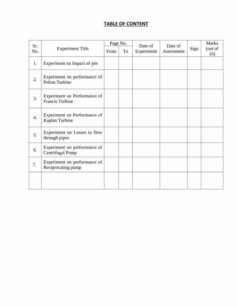
TABLE OF CONTENT
Sr.
No. Experiment Title
Page No. Date of
Experiment
Date of
Assessment Sign
Marks
(out of
10) From To
1. Experiment on Impact of jets
2. Experiment on performance of
Pelton Turbine
3. Experiment on Performance of
Francis Turbine
4. Experiment on Performance of
Kaplan Turbine
5. Experiment on Losses in flow
through pipes
6. Experiment on performance of
Centrifugal Pump
7. Experiment on performance of
Reciprocating pump
EXPERIMENT NO:1
IMPACT OF JET ON VANES
Aim: To determine the co-efficient of impact on vanes
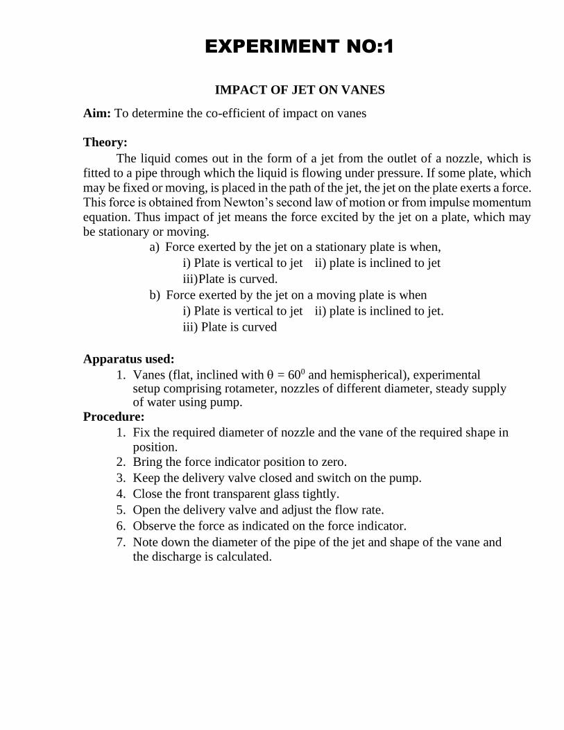
Theory: The liquid comes out in the form of a jet from the outlet of a nozzle, which is
fitted to a pipe through which the liquid is flowing under pressure. If some plate, which
may be fixed or moving, is placed in the path of the jet, the jet on the plate exerts a force. This force is obtained from Newton’s second law of motion or from impulse momentum
equation. Thus impact of jet means the force excited by the jet on a plate, which may be stationary or moving.
a) Force exerted by the jet on a stationary plate is when, i) Plate is vertical to jet ii) plate is inclined to jet iii) Plate is curved.
b) Force exerted by the jet on a moving plate is when
i) Plate is vertical to jet ii) plate is inclined to jet. iii) Plate is curved
Apparatus used: 1. Vanes (flat, inclined with = 600 and hemispherical), experimental
setup comprising rotameter, nozzles of different diameter, steady supply of water using pump.
Procedure: 1. Fix the required diameter of nozzle and the vane of the required shape in
position.
2. Bring the force indicator position to zero.
3. Keep the delivery valve closed and switch on the pump.
4. Close the front transparent glass tightly.
5. Open the delivery valve and adjust the flow rate.
6. Observe the force as indicated on the force indicator. 7. Note down the diameter of the pipe of the jet and shape of the vane and
the discharge is calculated.
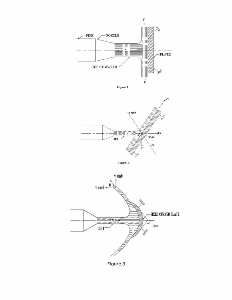
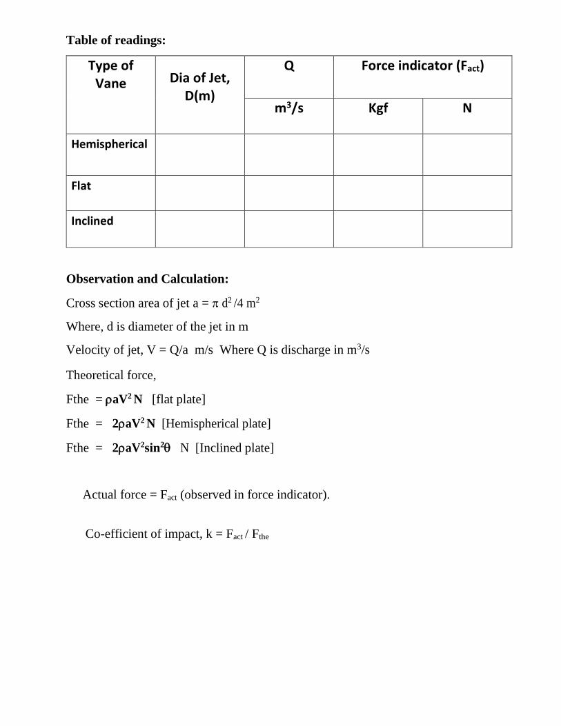
Table of readings:
Type of Vane Dia of Jet,
D(m)
Q Force indicator (Fact)
m3/s Kgf N
Hemispherical
Flat
Inclined
Observation and Calculation:
Cross section area of jet a = d2 /4 m2
Where, d is diameter of the jet in m
Velocity of jet, V = Q/a m/s Where Q is discharge in m3/s Theoretical force,
Fthe = aV2 N [flat plate]
Fthe = 2aV2 N [Hemispherical plate]
Fthe = 2aV2sin2 N [Inclined plate]
Actual force = Fact (observed in force indicator).
Co-efficient of impact, k = Fact / Fthe
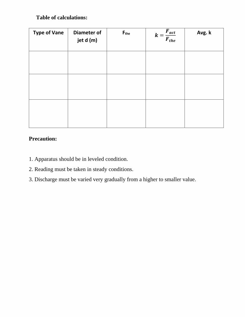
Table of calculations:
Type of Vane Diameter of
jet d (m)
Fthe 𝒌 =𝑭𝒂𝒄𝒕
𝑭𝒕𝒉𝒆 Avg. k
Precaution:
1. Apparatus should be in leveled condition.
2. Reading must be taken in steady conditions.
3. Discharge must be varied very gradually from a higher to smaller value.
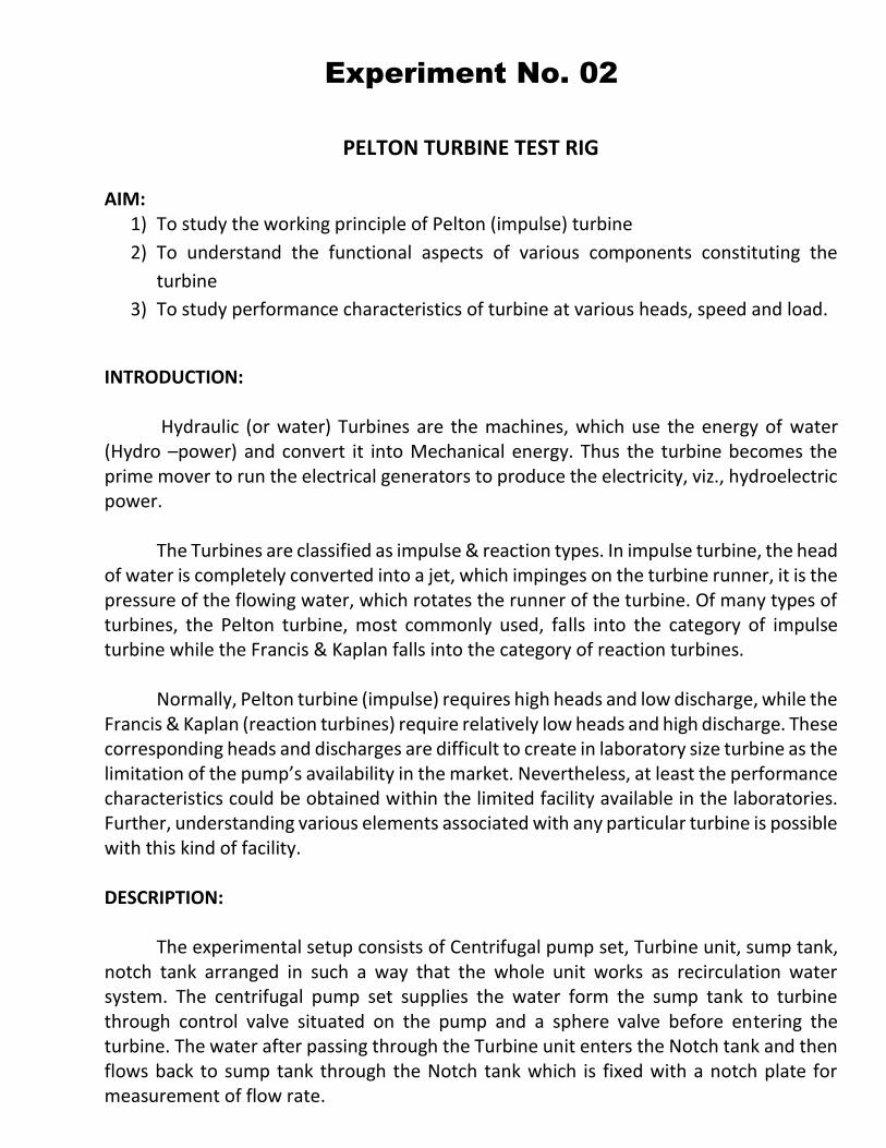
Experiment No. 02
PELTON TURBINE TEST RIG
AIM:
1) To study the working principle of Pelton (impulse) turbine
2) To understand the functional aspects of various components constituting the
turbine
3) To study performance characteristics of turbine at various heads, speed and load.
INTRODUCTION:
Hydraulic (or water) Turbines are the machines, which use the energy of water
(Hydro –power) and convert it into Mechanical energy. Thus the turbine becomes the prime mover to run the electrical generators to produce the electricity, viz., hydroelectric power.
The Turbines are classified as impulse & reaction types. In impulse turbine, the head
of water is completely converted into a jet, which impinges on the turbine runner, it is the pressure of the flowing water, which rotates the runner of the turbine. Of many types of turbines, the Pelton turbine, most commonly used, falls into the category of impulse turbine while the Francis & Kaplan falls into the category of reaction turbines.
Normally, Pelton turbine (impulse) requires high heads and low discharge, while the
Francis & Kaplan (reaction turbines) require relatively low heads and high discharge. These corresponding heads and discharges are difficult to create in laboratory size turbine as the limitation of the pump’s availability in the market. Nevertheless, at least the performance characteristics could be obtained within the limited facility available in the laboratories. Further, understanding various elements associated with any particular turbine is possible with this kind of facility. DESCRIPTION:
The experimental setup consists of Centrifugal pump set, Turbine unit, sump tank,
notch tank arranged in such a way that the whole unit works as recirculation water system. The centrifugal pump set supplies the water form the sump tank to turbine through control valve situated on the pump and a sphere valve before entering the turbine. The water after passing through the Turbine unit enters the Notch tank and then flows back to sump tank through the Notch tank which is fixed with a notch plate for measurement of flow rate.
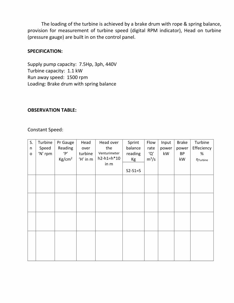
The loading of the turbine is achieved by a brake drum with rope & spring balance, provision for measurement of turbine speed (digital RPM indicator), Head on turbine (pressure gauge) are built in on the control panel.
SPECIFICATION: Supply pump capacity: 7.5Hp, 3ph, 440V Turbine capacity: 1.1 kW Run away speed: 1500 rpm Loading: Brake drum with spring balance
OBSERVATION TABLE: Constant Speed:
S.no
Turbine Speed
‘N’ rpm
Pr Gauge Reading
‘P’ Kg/cm2
Head over
turbine ‘H’ in m
Head over the
Venturimeter
h2-h1=h*10 in m
Sprint balance reading
Kg
Flow rate ‘Q’
m3/s
Input power
kW
Brake power
BP kW
Turbine Effeciency
% ηTurbine
S2-S1=S
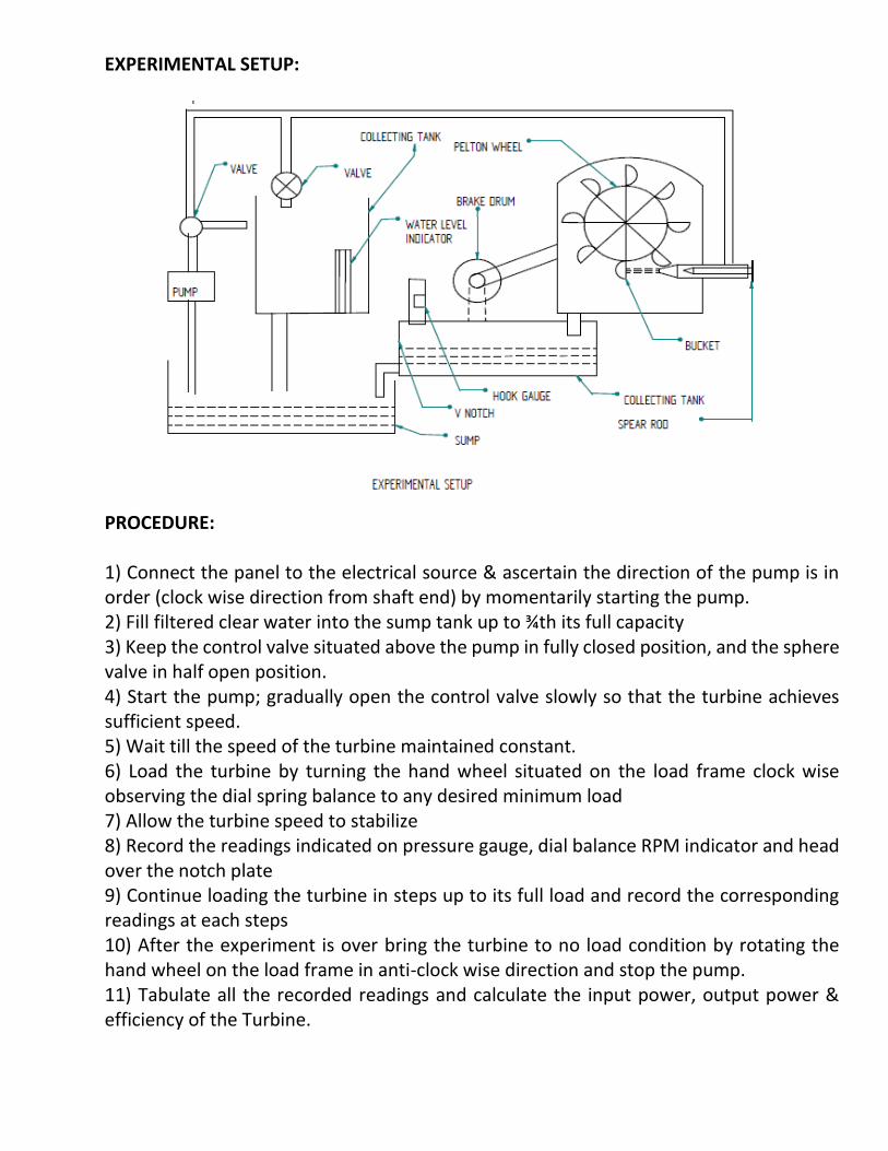
EXPERIMENTAL SETUP:
PROCEDURE: 1) Connect the panel to the electrical source & ascertain the direction of the pump is in order (clock wise direction from shaft end) by momentarily starting the pump. 2) Fill filtered clear water into the sump tank up to ¾th its full capacity 3) Keep the control valve situated above the pump in fully closed position, and the sphere valve in half open position. 4) Start the pump; gradually open the control valve slowly so that the turbine achieves sufficient speed. 5) Wait till the speed of the turbine maintained constant. 6) Load the turbine by turning the hand wheel situated on the load frame clock wise observing the dial spring balance to any desired minimum load 7) Allow the turbine speed to stabilize 8) Record the readings indicated on pressure gauge, dial balance RPM indicator and head over the notch plate 9) Continue loading the turbine in steps up to its full load and record the corresponding readings at each steps 10) After the experiment is over bring the turbine to no load condition by rotating the hand wheel on the load frame in anti-clock wise direction and stop the pump. 11) Tabulate all the recorded readings and calculate the input power, output power & efficiency of the Turbine.
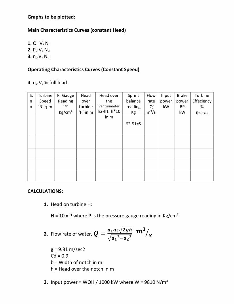
Graphs to be plotted: Main Characteristics Curves (constant Head) 1. Qu Vs Nu 2. Pu Vs Nu 3. ηo Vs Nu Operating Characteristics Curves (Constant Speed) 4. ηo Vs % full load.
S.no
Turbine Speed
‘N’ rpm
Pr Gauge Reading
‘P’ Kg/cm2
Head over
turbine ‘H’ in m
Head over the
Venturimeter
h2-h1=h*10 in m
Sprint balance reading
Kg
Flow rate ‘Q’
m3/s
Input power
kW
Brake power
BP kW
Turbine Effeciency
% ηTurbine
S2-S1=S
CALCULATIONS:
1. Head on turbine H:
H = 10 x P where P is the pressure gauge reading in Kg/cm2
2. Flow rate of water, 𝑸 =𝒂𝟏𝒂𝟐√𝟐𝒈𝒉
√𝒂𝟏𝟐−𝒂𝟐
𝟐 𝒎
𝟑
𝒔⁄
g = 9.81 m/sec2 Cd = 0.9 b = Width of notch in m h = Head over the notch in m
3. Input power = WQH / 1000 kW where W = 9810 N/m3
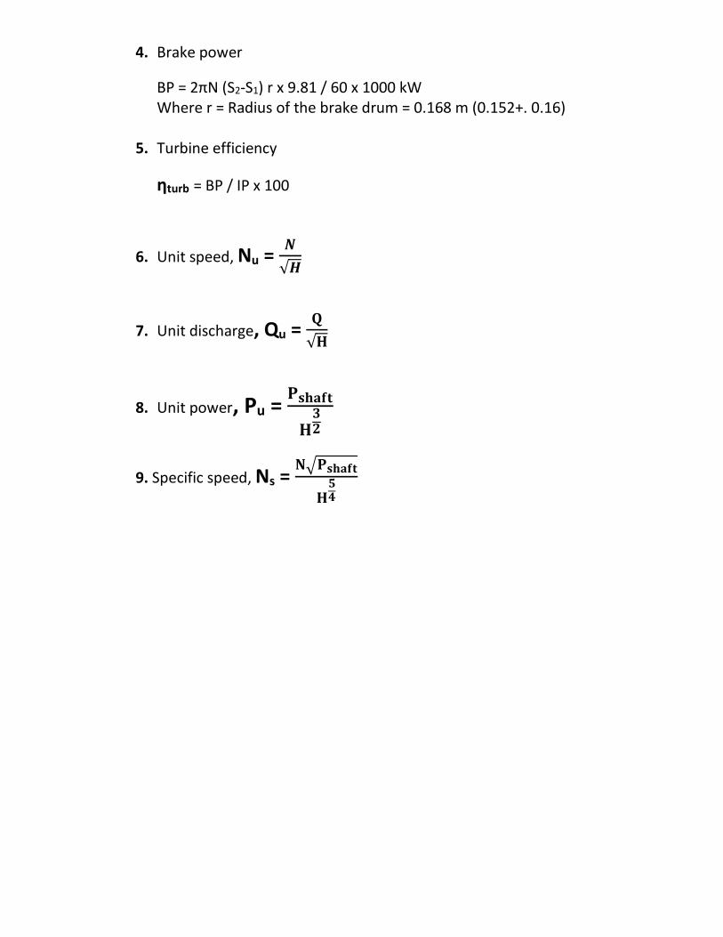
4. Brake power
BP = 2πN (S2-S1) r x 9.81 / 60 x 1000 kW Where r = Radius of the brake drum = 0.168 m (0.152+. 0.16)
5. Turbine efficiency
ηturb = BP / IP x 100
6. Unit speed, Nu = 𝑵
√𝑯
7. Unit discharge, Qu = 𝐐
√𝐇
8. Unit power, Pu = 𝐏𝐬𝐡𝐚𝐟𝐭
𝐇𝟑𝟐
9. Specific speed, Ns = 𝐍√𝐏𝐬𝐡𝐚𝐟𝐭
𝐇𝟓𝟒
Experiment No. 03
FRANCIS TURBINE TEST RIG AIM:
1. To study the working principle of Francis (reaction) turbine.
2. To understand the functional aspects of various components constituting the turbine. To study performance characteristics of turbine at various heads, flow rates and speeds
INTRODUCTION:
Hydraulic (water) Turbines are the machines, which use the energy of water (Hydro –power) and convert it into Mechanical energy, which is further converted into electrical energy. Thus the turbine becomes the prime mover to run the electrical generators to produce electricity (Hydroelectric power).
The Turbines are classified as impulse & reaction types. In impulse turbine, the head of water is completely converted into a jet, which exerts the force on the turbine; it is the pressure of the flowing water, which rotates the Impeller of the turbine. Of many types of turbine, the Pelton wheel, most commonly used, falls into the category of impulse turbine, while the Francis & Kaplan falls into the category of reaction turbines.
Normally, Pelton wheel (impulse turbine) requires high heads and low discharge, while the Francis & Kaplan (reaction turbines) require relatively low heads and high discharge. These corresponding heads and discharges are difficult to create in laboratory because of the limitation of required head & discharges. Nevertheless, an attempt has been made to study the performance characteristics within the limited facility available in the laboratories. Further, understanding various elements associated with any particular turbine is possible with this kind of facility. DESCRIPTION:
While the impulse turbine is discussed elsewhere in standard textbooks, Francis turbine (reaction type) which is of present concern consists of main components such as Impeller (runner), scroll casing and draft tube. Between the scroll casing and the Impeller there are guide vanes, which guides the water on to the impeller thus rotating the Impeller shaft. There are eight guide vanes, which can be turned about their own axis so that the angle of inclination may be adjusted while the turbine is in motion. When guide vane angles are varied, high efficiency can be obtained over wide range of operating conditions.
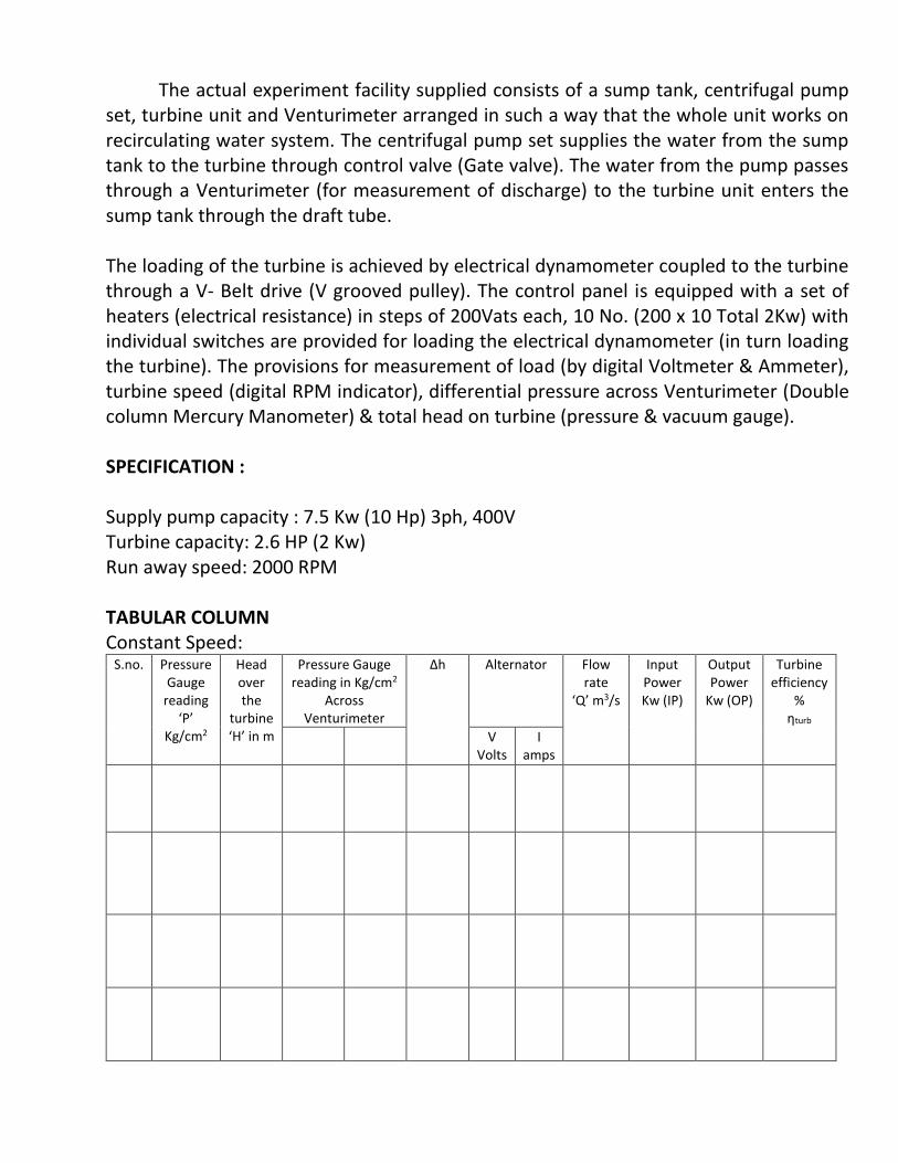
The actual experiment facility supplied consists of a sump tank, centrifugal pump
set, turbine unit and Venturimeter arranged in such a way that the whole unit works on recirculating water system. The centrifugal pump set supplies the water from the sump tank to the turbine through control valve (Gate valve). The water from the pump passes through a Venturimeter (for measurement of discharge) to the turbine unit enters the sump tank through the draft tube.
The loading of the turbine is achieved by electrical dynamometer coupled to the turbine through a V- Belt drive (V grooved pulley). The control panel is equipped with a set of heaters (electrical resistance) in steps of 200Vats each, 10 No. (200 x 10 Total 2Kw) with individual switches are provided for loading the electrical dynamometer (in turn loading the turbine). The provisions for measurement of load (by digital Voltmeter & Ammeter), turbine speed (digital RPM indicator), differential pressure across Venturimeter (Double column Mercury Manometer) & total head on turbine (pressure & vacuum gauge). SPECIFICATION : Supply pump capacity : 7.5 Kw (10 Hp) 3ph, 400V Turbine capacity: 2.6 HP (2 Kw) Run away speed: 2000 RPM TABULAR COLUMN Constant Speed:
S.no. Pressure Gauge
reading ‘P’
Kg/cm2
Head over the
turbine ‘H’ in m
Pressure Gauge reading in Kg/cm2
Across Venturimeter
Δh Alternator Flow rate
‘Q’ m3/s
Input Power Kw (IP)
Output Power
Kw (OP)
Turbine efficiency
% ηturb
V Volts
I amps
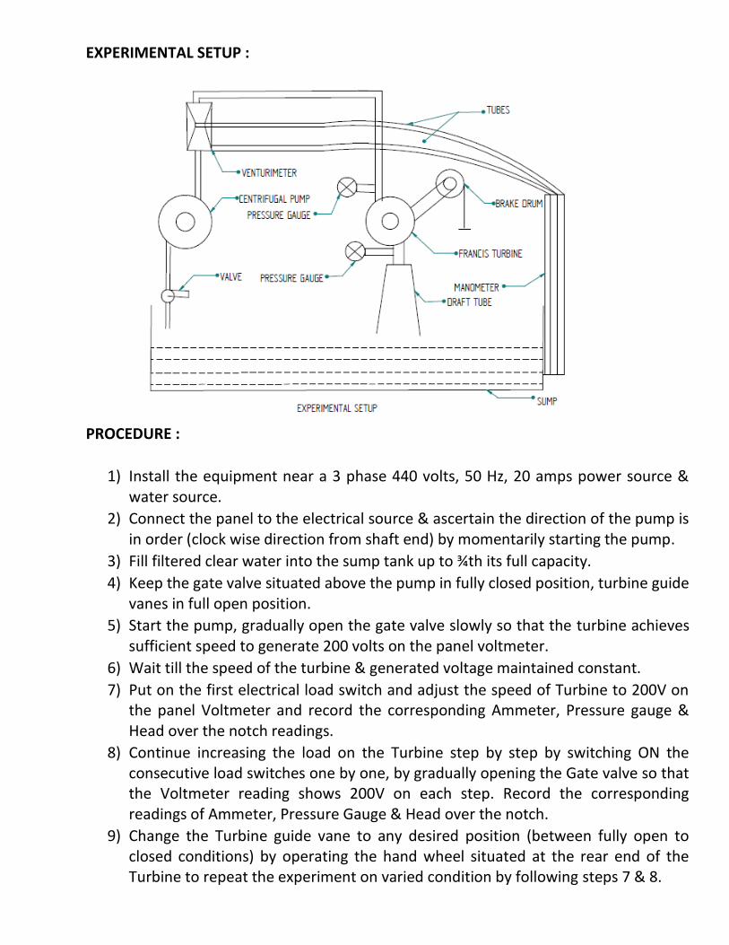
EXPERIMENTAL SETUP :
PROCEDURE :
1) Install the equipment near a 3 phase 440 volts, 50 Hz, 20 amps power source & water source.
2) Connect the panel to the electrical source & ascertain the direction of the pump is in order (clock wise direction from shaft end) by momentarily starting the pump.
3) Fill filtered clear water into the sump tank up to ¾th its full capacity.
4) Keep the gate valve situated above the pump in fully closed position, turbine guide vanes in full open position.
5) Start the pump, gradually open the gate valve slowly so that the turbine achieves sufficient speed to generate 200 volts on the panel voltmeter.
6) Wait till the speed of the turbine & generated voltage maintained constant.
7) Put on the first electrical load switch and adjust the speed of Turbine to 200V on the panel Voltmeter and record the corresponding Ammeter, Pressure gauge & Head over the notch readings.
8) Continue increasing the load on the Turbine step by step by switching ON the consecutive load switches one by one, by gradually opening the Gate valve so that the Voltmeter reading shows 200V on each step. Record the corresponding readings of Ammeter, Pressure Gauge & Head over the notch.
9) Change the Turbine guide vane to any desired position (between fully open to closed conditions) by operating the hand wheel situated at the rear end of the Turbine to repeat the experiment on varied condition by following steps 7 & 8.
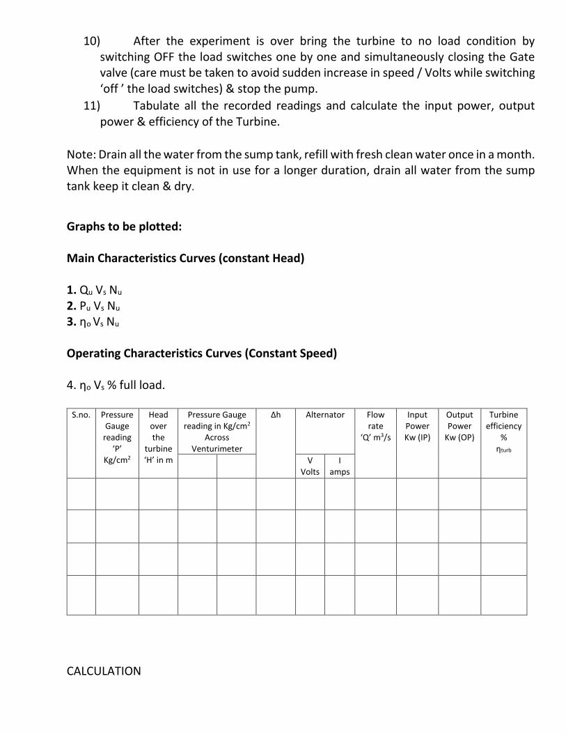
10) After the experiment is over bring the turbine to no load condition by switching OFF the load switches one by one and simultaneously closing the Gate valve (care must be taken to avoid sudden increase in speed / Volts while switching ‘off ’ the load switches) & stop the pump.
11) Tabulate all the recorded readings and calculate the input power, output power & efficiency of the Turbine.
Note: Drain all the water from the sump tank, refill with fresh clean water once in a month. When the equipment is not in use for a longer duration, drain all water from the sump tank keep it clean & dry.
Graphs to be plotted: Main Characteristics Curves (constant Head) 1. Qu Vs Nu 2. Pu Vs Nu 3. ηo Vs Nu Operating Characteristics Curves (Constant Speed) 4. ηo Vs % full load.
S.no. Pressure Gauge
reading ‘P’
Kg/cm2
Head over the
turbine ‘H’ in m
Pressure Gauge reading in Kg/cm2
Across Venturimeter
Δh Alternator Flow rate
‘Q’ m3/s
Input Power Kw (IP)
Output Power
Kw (OP)
Turbine efficiency
% ηturb
V Volts
I amps
CALCULATION
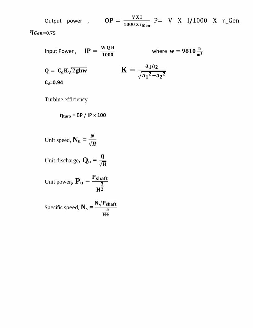
Output power , 𝐎𝐏 = 𝐕 𝐗 𝐈
𝟏𝟎𝟎𝟎 𝐗 𝛈𝐆𝐞𝐧P= V X I/1000 X η_Gen
𝜼𝑮𝒆𝒏=𝟎.𝟕𝟓 Input Power , 𝐈𝐏 =
𝐖 𝐐 𝐇
𝟏𝟎𝟎𝟎 where 𝐰 = 𝟗𝟖𝟏𝟎
𝐧
𝐦𝟑
𝐐 = 𝐂𝐝𝐊√𝟐𝐠𝐡𝐰 𝐊 =𝐚𝟏𝐚𝟐
√𝐚𝟏𝟐−𝐚𝟐
𝟐
Cd=0.94
Turbine efficiency
ηturb = BP / IP x 100
Unit speed, Nu = 𝑵
√𝑯
Unit discharge, Qu = 𝐐
√𝐇
Unit power, Pu = 𝐏𝐬𝐡𝐚𝐟𝐭
𝐇𝟑𝟐
Specific speed, Ns = 𝐍√𝐏𝐬𝐡𝐚𝐟𝐭
𝐇𝟓𝟒
EXPERIMENT NO - 04
KAPLAN TURBINE TEST RIG
AIM:
3. To study the working principle of Kaplan (reaction) turbine. 4. To understand the functional aspects of various components constituting the turbine. To
study performance characteristics of turbine at various heads, flow rates and speeds
INTRODUCTION:
Hydraulic (water) Turbines are the machines, which use the energy of water (Hydro –power) and convert
it into Mechanical energy, which is further converted into electrical energy. Thus the turbine becomes the
primover to run the electrical generators to produce electricity (Hydroelectric power).
The Turbines are classified as impulse & reaction types. In impulse turbine, the head of water
is completely converted into a jet, which exerts the force on the turbine; it is the pressure of the flowing water, which rotates the runner of the turbine. Of many types of turbine, the Pelton wheel, most
commonly used, falls into the category of impulse turbine, while the Francis & Kaplan falls into the category of reaction turbines.
Normally, Pelton wheel (impulse turbine) requires high heads and low discharge, while the
Francis & Kaplan (reaction turbines) require relatively low heads and high discharge. These
corresponding heads and discharges are difficult to create in laboratory because of the limitation of
required head & discharges. Nevertheless, an attempt has been made to study the performance
characteristics within the limited facility available in the laboratories. Further, understanding various
elements associated with any particular turbine is possible with this kind of facility.
DESCRIPTION:
While the impulse turbine is discussed elsewhere in standard textbooks, Kaplan turbine (reaction type)
which is of present concern consists of main components such as propeller (runner), scroll casing and
draft tube. Between the scroll casing and the runner, the water turns through right angle into axial
direction and passes over the runner and thus rotating the runner shaft. The runner has four blades,
which can be turned about their own axis so that the angle of inclination may be adjusted while the
turbine is in motion. The runner blade angles can be varied to obtain higher efficiency over wide range
of operating conditions. In other words even at part loads, when a low discharge is flowing over the
runner, a high efficiency can be attained in case of Kaplan turbine. Where as this provision does not
exist in Francis & Propeller turbines where the runner blade angles are fixed and integral with the
hub.
The actual experimental setup consist of a centrifugal pump set, turbine unit, sump tank, arranged in such
a way that the whole unit works on recirculating water system.
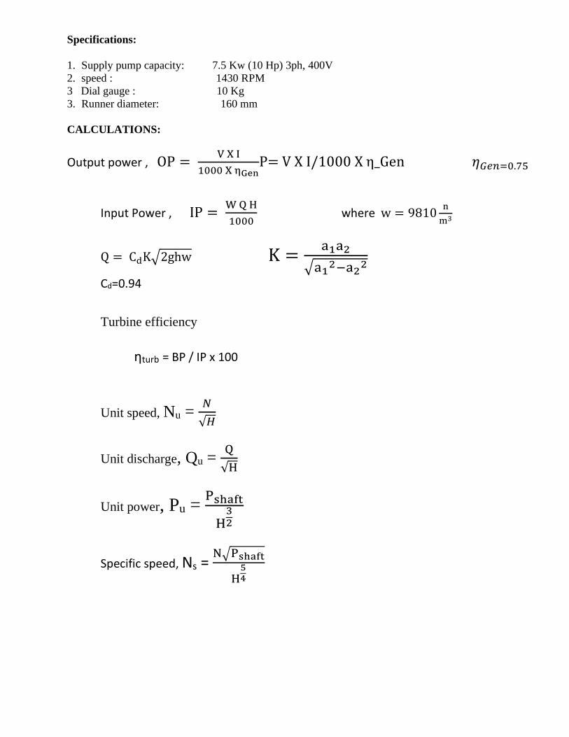
Specifications:
1. Supply pump capacity: 7.5 Kw (10 Hp) 3ph, 400V
2. speed : 1430 RPM
3 Dial gauge : 10 Kg
3. Runner diameter: 160 mm
CALCULATIONS:
Output power , OP = V X I
1000 X ηGenP= V X I/1000 X η_Gen 𝜂𝐺𝑒𝑛=0.75
Input Power , IP =
W Q H
1000 where w = 9810
n
m3
Q = CdK√2ghw K =a1a2
√a12−a2
2
Cd=0.94
Turbine efficiency
ηturb = BP / IP x 100
Unit speed, Nu = 𝑁
√𝐻
Unit discharge, Qu = Q
√H
Unit power, Pu = Pshaft
H32
Specific speed, Ns = N√Pshaft
H54
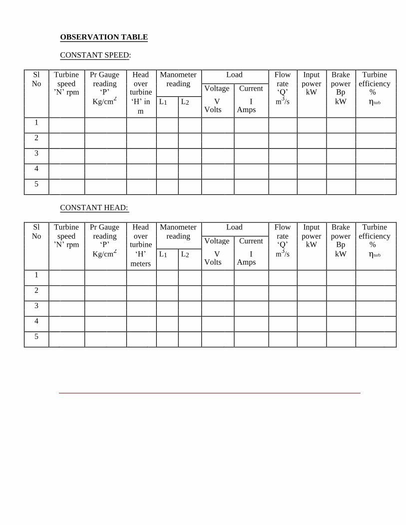
OBSERVATION TABLE
CONSTANT SPEED:
Sl Turbine Pr Gauge Head Manometer Load Flow Input Brake Turbine
No speed reading over reading
rate power power efficiency
Voltage Current
’N’ rpm ‘P’ turbine ‘Q’ kW Bp %
V
I
Kg/cm2 ‘H’ in L1 L2 m
3/s kW ηturb
m Volts Amps
1
2
3
4
5
CONSTANT HEAD:
Sl Turbine Pr Gauge Head Manometer Load Flow Input Brake Turbine
No speed reading over reading
rate power power efficiency
Voltage Current
’N’ rpm ‘P’ turbine ‘Q’ kW Bp %
V
I
Kg/cm2 ‘H’ L1 L2 m
3/s kW ηturb
meters Volts Amps
1
2
3
4
5
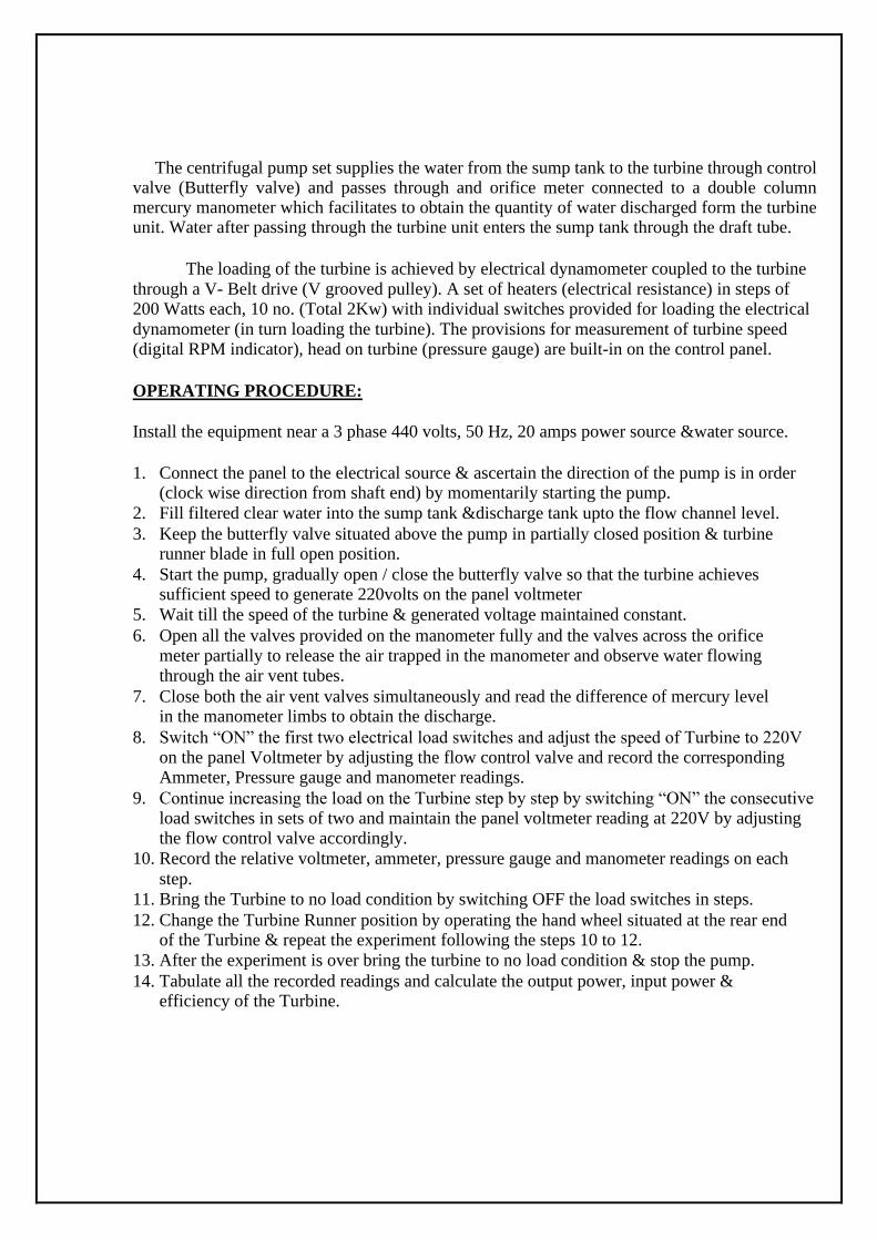
The centrifugal pump set supplies the water from the sump tank to the turbine through control valve (Butterfly valve) and passes through and orifice meter connected to a double column mercury manometer which facilitates to obtain the quantity of water discharged form the turbine unit. Water after passing through the turbine unit enters the sump tank through the draft tube.
The loading of the turbine is achieved by electrical dynamometer coupled to the turbine
through a V- Belt drive (V grooved pulley). A set of heaters (electrical resistance) in steps of 200 Watts each, 10 no. (Total 2Kw) with individual switches provided for loading the electrical
dynamometer (in turn loading the turbine). The provisions for measurement of turbine speed (digital RPM indicator), head on turbine (pressure gauge) are built-in on the control panel.
OPERATING PROCEDURE:
Install the equipment near a 3 phase 440 volts, 50 Hz, 20 amps power source &water source.
1. Connect the panel to the electrical source & ascertain the direction of the pump is in order (clock wise direction from shaft end) by momentarily starting the pump.
2. Fill filtered clear water into the sump tank &discharge tank upto the flow channel level. 3. Keep the butterfly valve situated above the pump in partially closed position & turbine
runner blade in full open position. 4. Start the pump, gradually open / close the butterfly valve so that the turbine achieves
sufficient speed to generate 220volts on the panel voltmeter 5. Wait till the speed of the turbine & generated voltage maintained constant. 6. Open all the valves provided on the manometer fully and the valves across the orifice
meter partially to release the air trapped in the manometer and observe water flowing through the air vent tubes.
7. Close both the air vent valves simultaneously and read the difference of mercury level in the manometer limbs to obtain the discharge.
8. Switch “ON” the first two electrical load switches and adjust the speed of Turbine to 220V on the panel Voltmeter by adjusting the flow control valve and record the corresponding Ammeter, Pressure gauge and manometer readings.
9. Continue increasing the load on the Turbine step by step by switching “ON” the consecutive load switches in sets of two and maintain the panel voltmeter reading at 220V by adjusting the flow control valve accordingly.
10. Record the relative voltmeter, ammeter, pressure gauge and manometer readings on each
step.
11. Bring the Turbine to no load condition by switching OFF the load switches in steps. 12. Change the Turbine Runner position by operating the hand wheel situated at the rear end
of the Turbine & repeat the experiment following the steps 10 to 12. 13. After the experiment is over bring the turbine to no load condition & stop the pump. 14. Tabulate all the recorded readings and calculate the output power, input power &
efficiency of the Turbine.
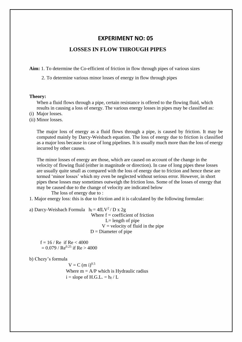
EXPERIMENT NO: 05
LOSSES IN FLOW THROUGH PIPES
Aim: 1. To determine the Co-efficient of friction in flow through pipes of various sizes
2. To determine various minor losses of energy in flow through pipes
Theory: When a fluid flows through a pipe, certain resistance is offered to the flowing fluid, which results in causing a loss of energy. The various energy losses in pipes may be classified as:
(i) Major losses.
(ii) Minor losses.
The major loss of energy as a fluid flows through a pipe, is caused by friction. It may be
computed mainly by Darcy-Weisbach equation. The loss of energy due to friction is classified as a major loss because in case of long pipelines. It is usually much more than the loss of energy
incurred by other causes.
The minor losses of energy are those, which are caused on account of the change in the
velocity of flowing fluid (either in magnitude or direction). In case of long pipes these losses
are usually quite small as compared with the loss of energy due to friction and hence these are
termed ‘minor losses’ which my even be neglected without serious error. However, in short
pipes these losses may sometimes outweigh the friction loss. Some of the losses of energy that
may be caused due to the change of velocity are indicated below The loss of energy due to :
1. Major energy loss: this is due to friction and it is calculated by the following formulae:
a) Darcy-Weisbach Formula hf = 4fLV2 / D x 2g Where f = coefficient of friction
L= length of pipe V = velocity of fluid in the pipe
D = Diameter of pipe f = 16 / Re if Re < 4000 = 0.079 / Re0.25 if Re > 4000
b) Chezy’s formula
V = C (m i)0.5
Where m = A/P which is Hydraulic radius
i = slope of H.G.L. = hf / L
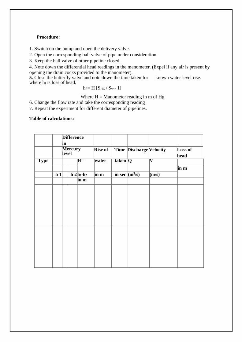
Procedure:
1. Switch on the pump and open the delivery valve.
2. Open the corresponding ball valve of pipe under consideration.
3. Keep the ball valve of other pipeline closed. 4. Note down the differential head readings in the manometer. (Expel if any air is present by opening the drain cocks provided to the manometer). 5. Close the butterfly valve and note down the time taken for known water level rise. where hf is loss of head.
hf = H [SHG / Sw - 1]
Where H = Manometer reading in m of Hg 6. Change the flow rate and take the corresponding reading
7. Repeat the experiment for different diameter of pipelines. Table of calculations:
Difference
in
Mercury level
Rise of Time Discharge Velocity Loss of
head Type H= water taken Q V
in m
h 1 h 2 h1-h2 in m in sec (m3/s) (m/s)
in m
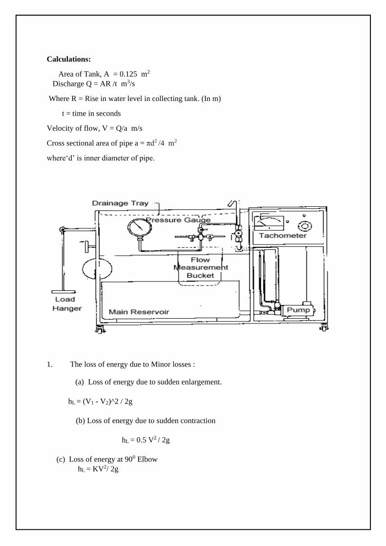
Calculations:
Area of Tank, A = 0.125 m2
Discharge Q = AR /t m3/s
Where R = Rise in water level in collecting tank. (In m)
t = time in seconds
Velocity of flow, V = Q/a m/s
Cross sectional area of pipe a = πd2 /4 m2
where‘d’ is inner diameter of pipe.
1. The loss of energy due to Minor losses :
(a) Loss of energy due to sudden enlargement.
hL = (V1 - V2)^2 / 2g
(b) Loss of energy due to sudden contraction
hL = 0.5 V2 / 2g
(c) Loss of energy at 900 Elbow
hL = KV2/ 2g
EXPERIMENT NO: 06
PERFORMANCE ANALYSIS OF CENTRIFUGAL PUMP
AIM: To conduct performance test on a Single stage Centrifugal pump test rig.
INTRODUCTION: A pump may be defined as mechanical device when interposed in a pipe line, converts the mechanical energy supplied to it from an external source into hydraulic energy, thus resulting in the flow of liquid from lower potential to higher potential.
The pumps are of major concern to most engineers and technicians. The types of pumps vary in
principle and design. The selection of the pump for any particular application is to be done by
understanding their characteristics. The most commonly used pumps for domestic, agricultural
and industrial are Centrifugal, axial flow, reciprocating, air jet, and diaphram and turbine pumps.
Most of these pumps fall into the main class namely Rotodynamic, Reciprocating (positive
displacement) and Fluid operated pumps.
THEORY: The principle of operation of a single stage centrifugal pump is covered under Rotodynamic pump category. In this pump, the liquid is made to rotate in a closed volute chamber. Thus
creating the centrifugal action, which gradually builds the pressure gradient towards outlet resulting in a continuous flow.
These pumps are of simple construction can be directly coupled to electric motor and more
suitable for handling clear, semi viscous, as well as turbid liquids. The hydraulic head per stage
at low flow rates is limited and hence not suitable for high heads, in case of single stage
centrifugal pumps. But as the pump in this case in a multi stage construction the pressure
gradually builds up in successive stages almost equally in each stage. Thus achieving
considerably higher heads. The multi stage centrifugal pump test rig allows the students to
understand and study the various characteristics and pressure build up pattern in individual
stages.
DESCRIPTION:
The single stage Centrifugal pump test rig mainly consists of: a) Single stage Centrifugal pump
b) AC Drive motor of suitable capacity coupled to pump by stepped pulley arrangement.
c) SS sump tank and measuring tank with a piezometer d) G. I. Pipe connections with necessary control valve etc… mounted on a neatly painted M.S.
structure. The panel board is equipped with an energy meter for measurement of power input to the motor, a digital RPM indicator to indicate the speed of the pump/motor, a Vacuum gauge to measure
suction head, & pressure gauge for measurement of delivery head, a starter of suitable capacity, indicating lamps and fuse etc.
Experimental Procedures:
1. Clean the apparatus and make all tanksfree from dust 2. Close the drain valve provided
3. Open flow control valve given on the water discharge 4. now switch on the main power supply 220 V AC , 50 Hz.
5. Operate the flow control valveto regulate the flow of water.
6. Set the desired RPM of motor/ Pump 7. Operate the control valve to regulate the suction of pump
8. Record discharge pressure by means of pressure gauge 9. Record suction pressure by means of suction gauge.
10. Measure the discharge by measuring tank by using stop watch. 11. Repeat the same procedure for different speed.
SPECIFICATIONS:
Pump 1.02HP/0.8KW, 2900 RPM, Single phase
Pressure gauge Bourden type Water circulation by Pump
Stop watch Electronic
OBSERVATIONS:
1 kg / cm2 = 760 mm of Hg
Density of water = 1000 Kg / m3
Area of collecting tank = 0.1 m2
Discharge rate “ Q ” in m3 / s
Q = A X h / t
where ‘h’ is height of water collected in measuring tank for a time interval of ‘t’ sec.
Total head “ H ” in m
H =10(Delivery Pressure + Vacuum head)
=10(P + Pv )
where P is pressure in kg / cm2 , Pv is the Vacuum in mm of Hg
p=(1.032+ pressure reading) Pv=(1.032- (suction pressure reading x 1.33 x 10⁻³
)
Data: Energy meter constant E.M.C. = 6400 pulses/kw-h
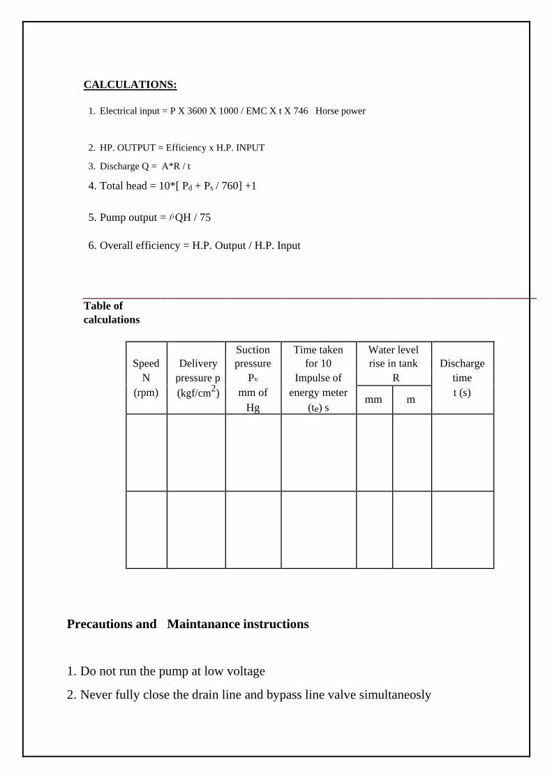
CALCULATIONS:
1. Electrical input = P X 3600 X 1000 / EMC X t X 746 Horse power
2. HP. OUTPUT = Efficiency x H.P. INPUT
3. Discharge Q = A*R / t
4. Total head = 10*[ Pd + Ps / 760] +1
5. Pump output = QH / 75
6. Overall efficiency = H.P. Output / H.P. Input
Table of
calculations
Suction Time taken Water level
Speed Delivery pressure for 10 rise in tank Discharge
N pressure p Pv Impulse of R time
(rpm)
(kgf/cm2) mm of energy meter
t (s)
mm
m
Hg (te) s
Precautions and Maintanance instructions
1. Do not run the pump at low voltage
2. Never fully close the drain line and bypass line valve simultaneosly

3. Always keep apparatus free from dust
4. Frequently grease/oil the rotating parts
5. Always use clean water.

EXPERIMENT NO: 07
PERFORMANCE ANALYSIS OF RECIPROCATING PUMP
AIM: To study the performance and characteristics of reciprocating pump and to determine the efficiency of
the pump
INTRODUCTION: In general, a pump may be defined as mechanical device when connected in a pipe line, can
convert the mechanical energy into hydraulic energy, thus resulting in the flow of liquid from lower potential to higher potential. The pumps are of major concern to most engineers and technicians. The types of pumps vary in
principle and design. The selection of the pump for any particular application is to be done by
understanding their characteristics. The most commonly used pumps for domestic, agricultural
and industrial are Centrifugal, axial flow (stage pumps), reciprocating, air jet, and diaphram and
turbine pumps. These pumps fall mainly into a category of rotodynamic, reciprocating (positive
displacement) and fluid operated pumps.
THEORY: Reciprocating pump is a positive displacement pump. It mainly consists of a piston reciprocating
inside a cylinder thus performing suction and delivery strokes. The cylinder is alternately filled
and emptied by forcing and drawing the liquid by mechanical motion. This type is called positive
type. Delivery and suction pipes are connected to a cylinder. Each of the two pipes is provided
with a non-return valve. The function of which is to ensure unidirectional flow of liquid. It
generally operates at low speed and is therefore to be coupled to a motor with V-belt. It is stable
for small discharge and high heads. Generally these pumps are used for feeding small boilers, for
lifting water to a higher heads & for pumping light oil. The present test rig allows the students to
understand and draw the operating characteristics at various heads, flow rates and speeds.
DISCRIPTION:
The Reciprocating pump test rig mainly consists of: a) Double stroke Reciprocating pump b) AC Drive motor of suitable capacity coupled with a belt drive Variable speed stepped cone pully. c) SS sump tank, SS measuring tank with a piezometer d) G. I. Pipe connections with necessary control valve etc… mounted on a neatly painted M.S. structure. e) The panel board is equipped with an energy meter for measurement of power input to the
motor, a digital RPM indicator to indicate the speed of the pump, a Vacuum gauge to measure suction head , a pressure gauges for measurement of delivery head. a three phase starter of suitable capacity,
main indicating lamps and fuses.
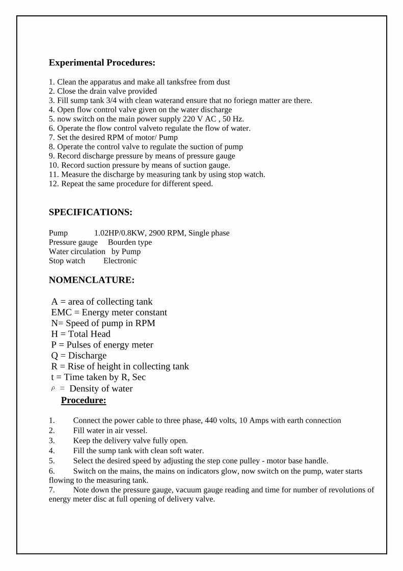
Experimental Procedures:
1. Clean the apparatus and make all tanksfree from dust 2. Close the drain valve provided
3. Fill sump tank 3/4 with clean waterand ensure that no foriegn matter are there. 4. Open flow control valve given on the water discharge
5. now switch on the main power supply 220 V AC , 50 Hz.
6. Operate the flow control valveto regulate the flow of water. 7. Set the desired RPM of motor/ Pump
8. Operate the control valve to regulate the suction of pump 9. Record discharge pressure by means of pressure gauge
10. Record suction pressure by means of suction gauge. 11. Measure the discharge by measuring tank by using stop watch.
12. Repeat the same procedure for different speed.
SPECIFICATIONS:
Pump 1.02HP/0.8KW, 2900 RPM, Single phase
Pressure gauge Bourden type
Water circulation by Pump Stop watch Electronic
NOMENCLATURE:
A = area of collecting tank EMC = Energy meter constant
N= Speed of pump in RPM H = Total Head
P = Pulses of energy meter Q = Discharge
R = Rise of height in collecting tank t = Time taken by R, Sec
= Density of water
Procedure:
1. Connect the power cable to three phase, 440 volts, 10 Amps with earth connection
2. Fill water in air vessel.
3. Keep the delivery valve fully open.
4. Fill the sump tank with clean soft water.
5. Select the desired speed by adjusting the step cone pulley - motor base handle. 6. Switch on the mains, the mains on indicators glow, now switch on the pump, water starts flowing to the measuring tank. 7. Note down the pressure gauge, vacuum gauge reading and time for number of revolutions of energy meter disc at full opening of delivery valve.
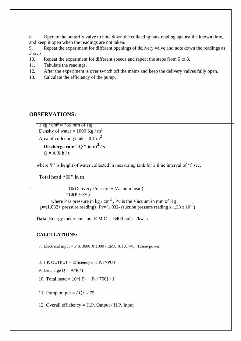
8. Operate the butterfly valve to note down the collecting tank reading against the known time, and keep it open when the readings are not taken. 9. Repeat the experiment for different openings of delivery valve and note down the readings as above 10. Repeat the experiment for different speeds and repeat the steps from 5 to 8.
11. Tabulate the readings.
12. After the experiment is over switch off the mains and keep the delivery valves fully open.
13. Calculate the efficiency of the pump.
OBSERVATIONS:
1 kg / cm2 = 760 mm of Hg
Density of water = 1000 Kg / m3
Area of collecting tank = 0.1 m2
Discharge rate “ Q ” in m3 / s
Q = A X h / t
where ‘h’ is height of water collected in measuring tank for a time interval of ‘t’ sec.
Total head “ H ” in m
I =10(Delivery Pressure + Vacuum head)
=10(P + Pv )
where P is pressure in kg / cm2 , Pv is the Vacuum in mm of Hg
p=(1.032+ pressure reading) Pv=(1.032- (suction pressure reading x 1.33 x 10⁻³
)
Data: Energy meter constant E.M.C. = 6400 pulses/kw-h
CALCULATIONS:
7. Electrical input = P X 3600 X 1000 / EMC X t X 746 Horse power
8. HP. OUTPUT = Efficiency x H.P. INPUT
9. Discharge Q = A*R / t
10. Total head = 10*[ Pd + Ps / 760] +1
11. Pump output = QH / 75
12. Overall efficiency = H.P. Output / H.P. Input

Table of
calculations
Suction Time taken Water level
Speed Delivery pressure for 10 rise in tank Discharge
N pressure p Pv Impulse of R time
(rpm)
(kgf/cm2) mm of energy meter
t (s)
mm
m
Hg (te) s
Precautions and Maintanance instructions
6. Do not run the pump at low voltage
7. Never fully close the drain line and bypass line valve simultaneosly
8. Always keep apparatus free from dust
9. Frequently grease/oil the rotating parts
10. Always use clean water