design alliance inc. 14225 university suite 110 waukee ... and plans.pdf · ptn pwd plas. pl. oph...
TRANSCRIPT

MATERIALS LEGEND
TERRAZZO
ASPHALT
POROUS FILL
CONCRETE
CONCRETE MASONRY
CONCRETE/PRECAST
STONE
GLAZING
BRICK
METAL
BACKFILL
REFER TO SITE PLAN, REFLECTED CEILING PLAN.MECHANICAL, AND ELECTRICAL DRAWINGS FORADDITIONAL MATERIALS LEGEND AND SYMBOLS.
NOTE:
EARTH
WOOD-FINISHED
WOOD-ROUGH
RIGID INSULATION
BATT INSULATION ORBLOWN INSULATION
GYPSUM WALLBOARD
METAL STUD W/GYPSUM WALLBOARD
METAL STUD W/GYPSUMWALLBOARD & SOUNDINSULATION
REFER TO FLOOR PLAN AND SECTIONS FORSPECIFIC PARTITION TYPES.
PLYWOOD
ABBREVIATIONS
WELDED WIRE MESHWELDED WIRE FABRIC
VINYL COMPOSITION TILEUNLESS NOTED OTHERWISE
TOP OF MASONRYTOP OF CONCRETE
TONGUE AND GROOVE
OUTSIDE DIAMETER
MASONRY OPENING
SEALANTSNT.FLOOR DRAINF.D.
INSIDE DIAMETERHARDWOODHORIZONTALHOLLOW METAL
HARDBOARDGYPSUM BOARD
GALVANIZED
FOUNDATION
FINISH TO FINISH
H.W.
INT.INSUL.I.D.
INTERIORINSULATION
H.C./HANDI.
G.B./GYP. BD.
HORIZ.H.M.
HT./HGT.H.B.
GL.GALV.GA.FDTN.FTG.FR.FL./FLR.F.L.FIN.F/F
HANDICAPHEIGHT
GLASS
GAUGE
FOOTINGFRAMEFLOORFLOW LINEFINISH
W.W.M.W.W.F.W.P.W.G.WD.W/OW/VERT.V.C.T.U.N.O.TERMTYP.T.W.TR.T.P.T.O.M.T.O.C.THRESH.T.G.T>.C.
WOOD
WATER PROOFINGWIRE GLASS
TOP OF WALL
WITHOUTWITHVERTICAL
TERMINATETYPICAL
TREADTELEPHONE POLE
THRESHOLDTEMPERED GLASS
TOP OF CURBFIRE EXTINGUSHER CABINETFIELD VERIFY
ELECTRICAL
EXTERIOR INSULATED FACING SYSTEMEXPANSION JOINT
DOWNSPOUT
DEMOLISH (TION)CERAMIC TILECONTRACTORCONTINUOUSCONSTRUCTIONCENTER LINECONTROL JOINT
COORDINATE (TION)CONNECT (ION)
BENCHMARK
BLOCK (ING)ARCHITECTURALAPPROXIMATELYADJUSTABLEALTERNATELY
ANCHOR BOLTACCESS PANEL
DEMO
EL./ELEV.
F.E.C.F.V.EXT.EXP.EXIST.EQ.ELEC.
E.I.F.S.E.J.EA.DWG.D.S.DN.DIM.DTL.
ELEVATION
EXTERIOREXPANSIONEXISTINGEQUAL
EACHDRAWING
DOWNDIMENSIONDETAIL
C.T./CER.T.
COL.
CONTR.CONT.CONST.C.L.C.J.CONC.
CLG.COORD.CONN.CAB.BRG.BOT.B.M.BLDG.
COLUMNCONCRETE
CEILING
CABINETBEARINGBOTTOM
BUILDING
AB
BM.BLK.ARCH.APPROX.ADJ.ALT.ALUM.AC.
AP
BEAM
ALUMINUMACOUSTIC
RTU
SIM.STRUCT.SUSP.STL.S.T.S.C.SECT.SQ.SPEC.SHT.S.A.
R.D.R.C.RM.REQ'DREINF.RR.A.Q.T.PTNPWDPLAS.PL.OPHOPNG.
O.D.O.C.O.A.NO.#N.T.S.
O.F.C.I.
MAT.
REINFORCE
SIMILARSTRUCTURALSUSPENDEDSTEELSTEEL TUBESOLID CORESECTIONSQUARESPECIFICATIONSHEETSUPPLY AIRROOF TOP UNITROOF DRAINROOF CURBROOMREQUIRED
RISERRETURN AIRQUARRY TILEPARTITIONPLYWOODPLASTERPLATEOPPOSITE HANDOPENING
ON CENTEROVERALLNUMBERNOT TO SCALE
OWNER FURNISHED CONTRACTOR INSTALLED
MATERIALMISC.MIN.MFR.MET.M.O.MAX.MAS.LT.WT.LAM.JT.
MISCELLANEOUSMINIMUMMANUFACTURERMETAL
MAXIMUMMASONRYLIGHT WEIGHTLAMINATEDJOINT
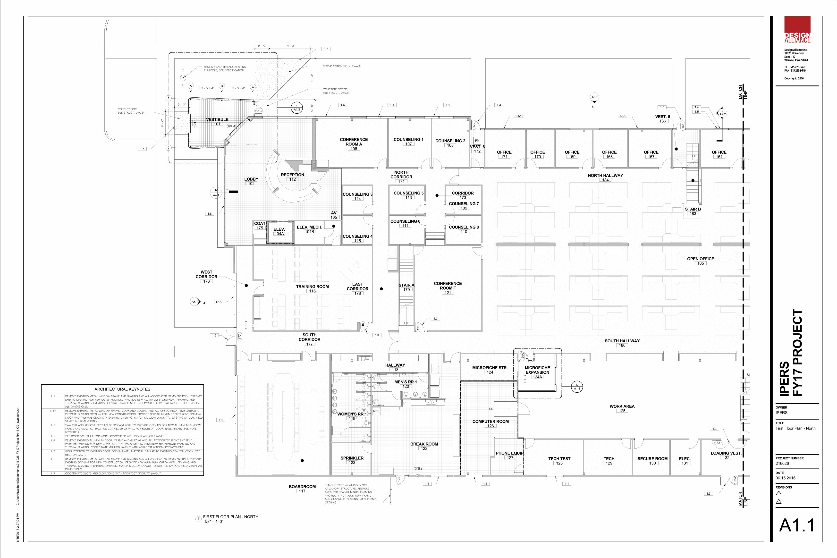
A1.1 FIRST FLOOR PLAN - NORTHA1.2 FIRST FLOOR PLAN - SOUTHA1.3 ENLARGED PLANSA4.1 DOOR & WINDOW TYPES, SCHEDULES & DETAILSA5.1 EXTERIOR ELEVATIONSA7.1 WALL SECTIONSA7.2 WALL SECTIONS
STRUCTURAL
ELECTRICAL
+9'-0"A.F.F.
C
206
BOYS RESTROOM
213
A-1
1
A-13
2
A-1
1
C
SYMBOLS
WALL TYPE
& NUMBERROOM NAME
ELEVATION LINE DOOR DESIGNATION
WINDOW TYPE
SHEET NUMBER
DETAIL NUMBER
SECTION
ELEVATION
LIST OF DRAWINGS
PROJECT LOCATION
GENERAL CONSTRUCTIONG0.0 COVER SHEET AND GENERAL INFORMATIONG1.1 CODE REVIEW
ARCHITECTURAL
ARCHITECT:Design Alliance, Inc.14225 University Avenue, Suite 100Waukee, Iowa 50263Phone: (515) 225-3469Fax: (515) 225-9649
ELECTRICAL ENGINEER:Twin Rivers Engineering1000 Illinois StreetDes Moines, Iowa 50314Phone: (515) 288-3679, Ext. 301Fax: (515) 288-4012
PROJECT TEAM
S0.1 STRUCTURAL NOTESS1.1 STRUCTURAL PLANS & DETAILS
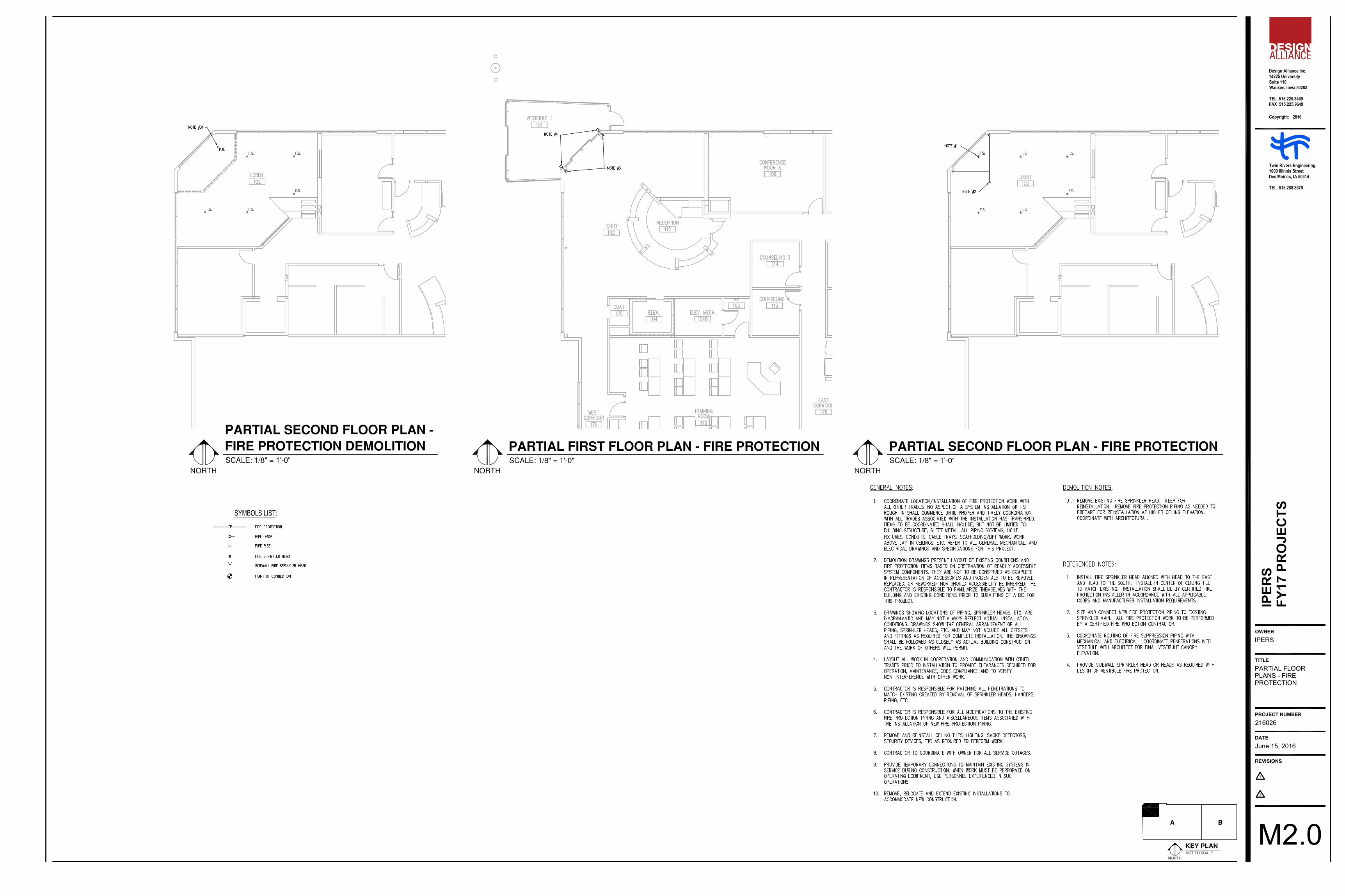
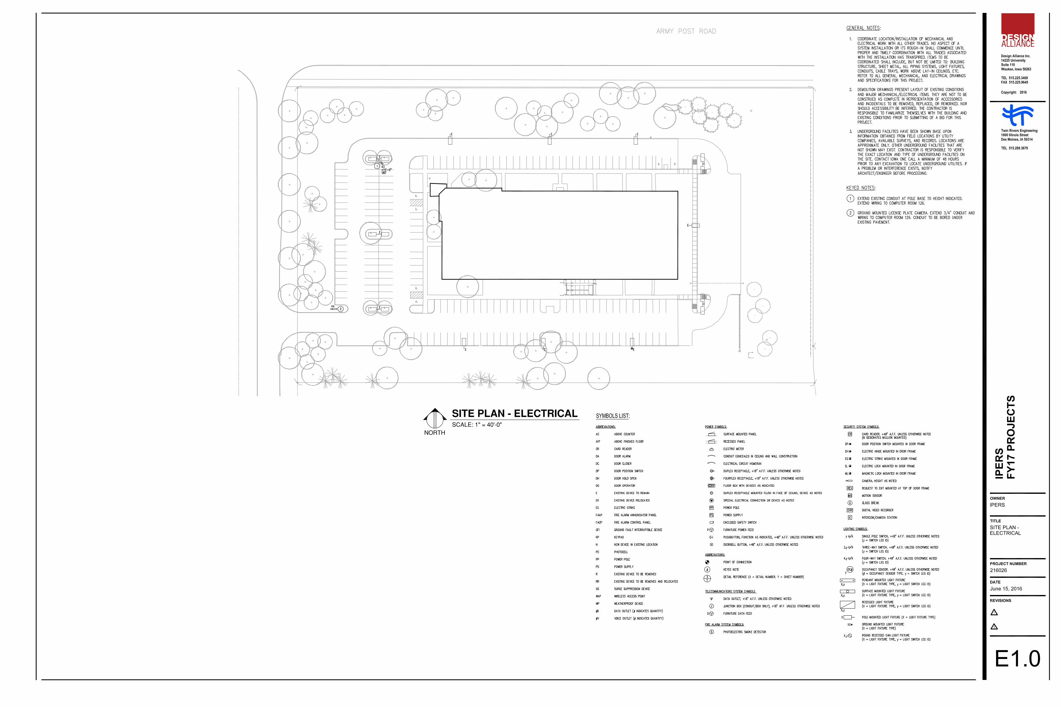
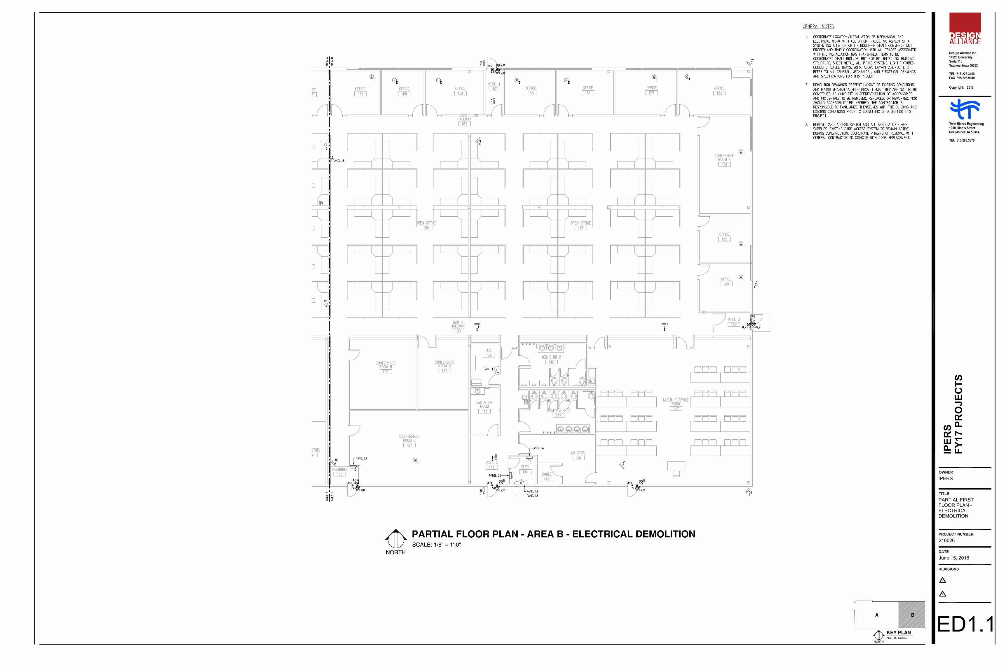
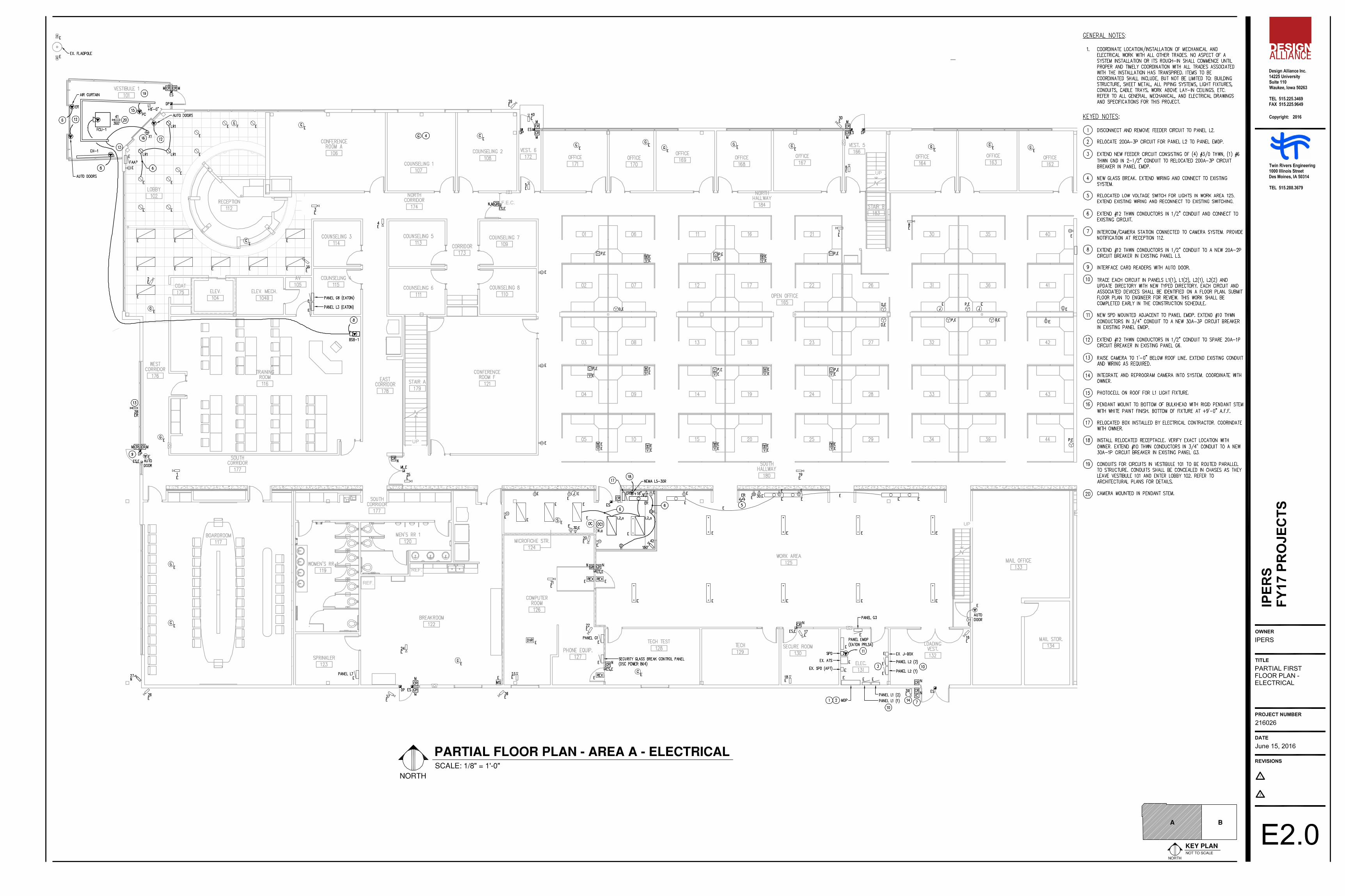
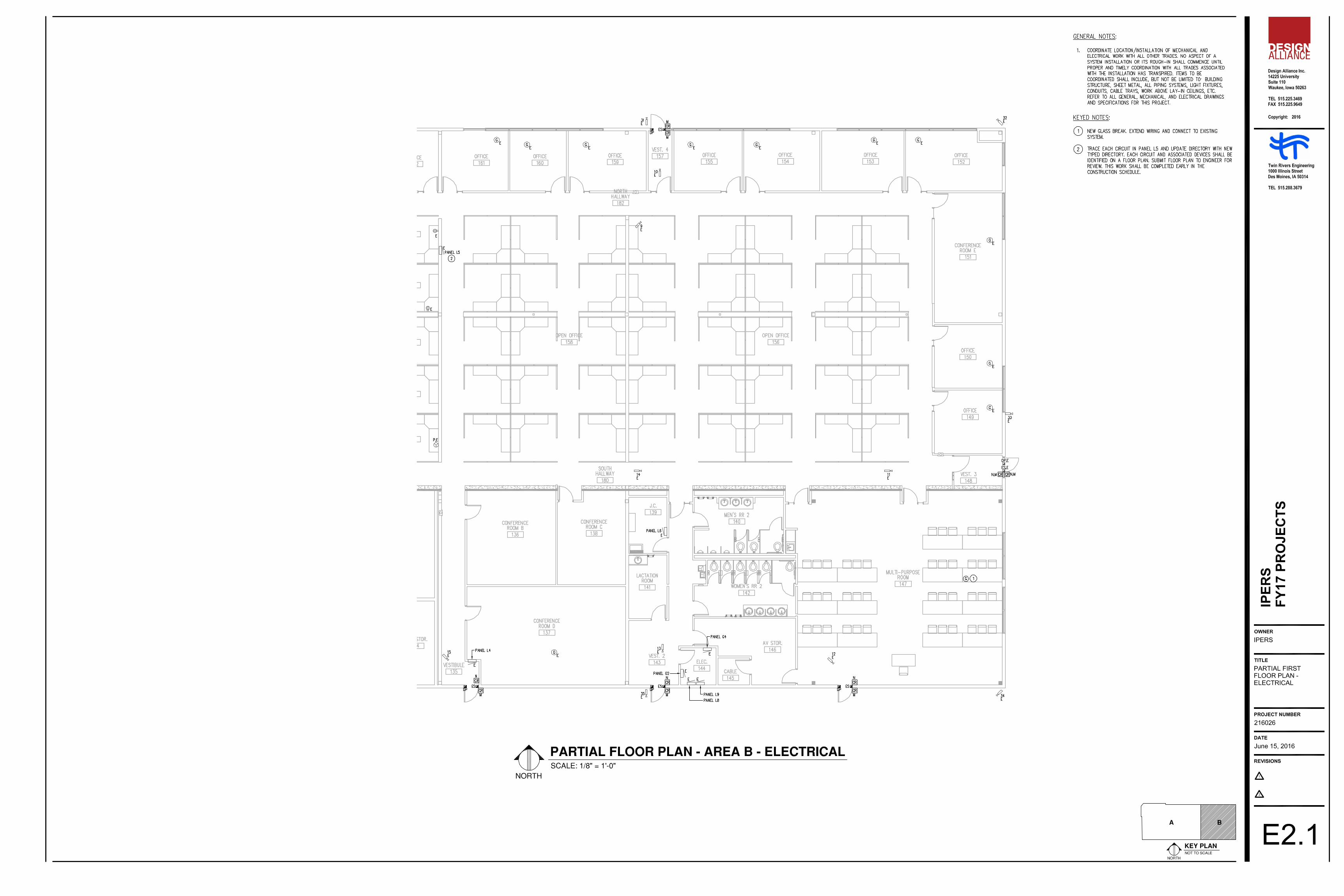
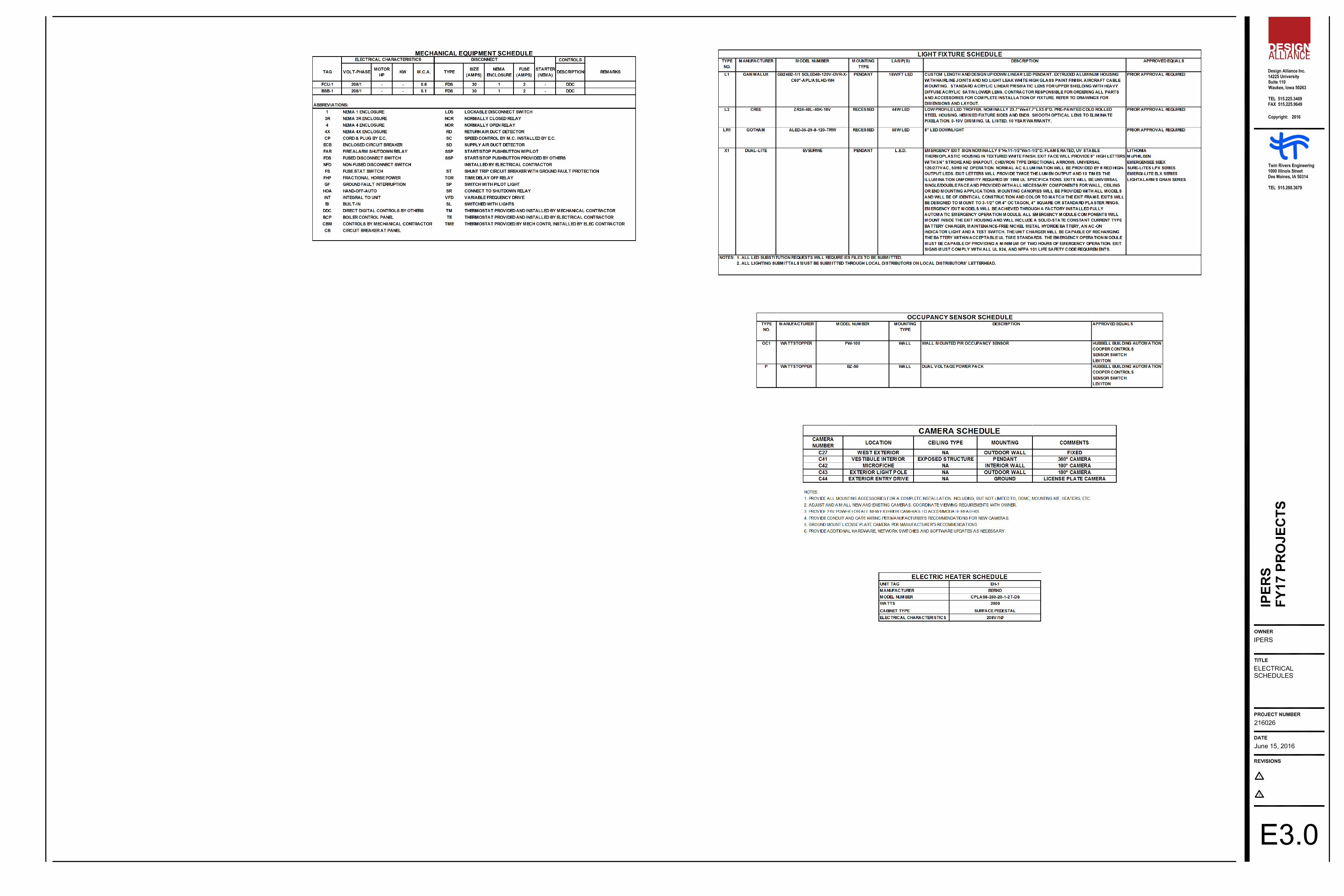
E1.0 SITE PLAN - ELECTRICALED1.0 PARTIAL FIRST FLOOR PLAN - ELECTRICAL DEMOLITIONED1.1 PARTIAL FIRST FLOOR PLAN - ELECTRICAL DEMOLITIONE2.0 PARTIAL FIRST FLOOR PLAN - ELECTRICALE2.1 PARTIAL FIRST FLOOR PLAN - ELECTRICALE3.0 ELECTRICAL SCHEDULES
IPERS7401 REGISTER DRIVEDES MOINES, IA 50321
STRUCTURAL ENGINEER:Charles Saul Engineering4308 University AvenueDes Moines, Iowa 50311Phone: (515) 279-3900
REG
I ST ER ED A RCH I TEC
T
I O W A
2287
DAV
I DJ . HARR ISON
DAVID J. HARRISON
I hereby certify that the portion of this technical submission described below wasprepared by me or under my direct personal supervision and responsible charge.I am a duly registered architect under the laws fo the state of Iowa.
Signature:
Date Issued:
Pages or sheets covered by this seal:
Date
BRAD A. STORK, P.E.
I hereby certify that this engineering document was prepared by me or under my directpersonal supervision and that I am a duly licensed Professional Engineer under the lawsof the State of Iowa.
Signature Date
My license renewal date is December 31, 2017
Pages or sheets covered by this seal:
BRAD A.STORK17332
LIC
EN
SE
DPROFESSIONA L
ENG
INE
ER
* IO W A *
DENNIS M.BENNETT
14202
LIC
EN
SE
DPROFESSIONA L
ENG
INE
ER
* IO W A *
DENNIS M. BENNETT, P.E.
I hereby certify that this engineering document was prepared by me or under my directpersonal supervision and that I am a duly licensed Professional Engineer under the lawsof the State of Iowa.
Signature Date
My license renewal date is December 31, 2016
Pages or sheets covered by this seal:
G-series, A-series
S-series
E-series
DAVID J.LOSEN14845
LIC
EN
SE
DPROFESSIONA L
ENG
INE
ER
* IO W A *
DAVID J. LOSEN, P.E.
I hereby certify that this engineering document was prepared by me or under my directpersonal supervision and that I am a duly licensed Professional Engineer under the lawsof the State of Iowa.
Signature Date
My license renewal date is December 31, 2016
Pages or sheets covered by this seal: E-series
MECHANICALM1.0 PARTIAL FLOOR PLANS - MECHANICALM2.0 PARTIAL FLOOR PLANS - FIRE PROTECTION
Design Alliance Inc.14225 UniversitySuite 110Waukee, Iowa 50263
TEL 515.225.3469FAX 515.225.9649
1
2
Copyright: 2016
OWNER
TITLE
PROJECT NUMBER
DATE
REVISIONS
C:\U
sers
\twol
bers
\Doc
umen
ts\2
1602
6-FY
17Pr
ojec
t-RA1
6-C
D_t
wol
bers
.rvt
6/15
/201
6 2:
27:3
5 PM
IPER
S
G0.0
06.15.2016
216026
Cover Sheet andGeneral Information
IPERS
FY17
PRO
JECT
FY17CAPITAL IMPROVEMENT PROJECTS
UP
UP
DN
UP
F.E.C.
F.E.C.
F.E.C.
F.E.
C.
F.E.C.
F.E.
C.
F.E.C.
F.E.C.
F.E.
C.
F.E.C.
DN
DN
F.E.C.
F.E.C.
699 SF
CONFERENCE ROOM D137
383 SF
CONFERENCE ROOM B136
512 SF
COMPUTER ROOM126
1257 SF
BOARDROOM117
147 SF
SPRINKLER123
904 SF
BREAK ROOM122
318 SF
WOMEN'S RR 1119
190 SF
MEN'S RR 1120
207 SF
HALLWAY118
Redundant Room
LOBBY102
937 SF
VESTIBULE101
412 SF
CONFERENCE ROOM A106 245 SF
COUNSELING 1107
213 SF
COUNSELING 2108
61 SF
VEST. 6172
176 SF
OFFICE171
123 SF
OFFICE170
161 SF
OFFICE169 151 SF
OFFICE168
189 SF
OFFICE167
115 SF
VEST. 5166
185 SF
OFFICE164
162 SF
OFFICE163
150 SF
OFFICE162
186 SF
OFFICE161
159 SF
OFFICE160
216 SF
OFFICE159
67 SF
VEST. 4157
192 SF
OFFICE155
211 SF
OFFICE154
229 SF
OFFICE153 257 SF
OFFICE152
405 SF
CONFERENCE ROOM E151
198 SF
OFFICE150
198 SF
OFFICE149
76 SF
VEST. 3148
1821 SF
MULTI-PURPOSE ROOM147
247 SF
WOMEN'S RR 2142
223 SF
AV STOR.146
39 SF
CABLE145
60 SF
ELEC.144
306 SF
VEST. 2143
112 SF
LACTATIONROOM
141
228 SF
MEN'S RR 2140
99 SF
J.C.139
280 SF
CONFERENCE ROOM C138
174 SF
MAIL STOR.134 227 SF
VESTIBULE135
673 SF
MAIL OFFICE133
206 SF
LOADING VEST.132
122 SF
ELEC.131
149 SF
SECURE ROOM130
198 SF
TECH129
242 SF
TECH TEST128128 SF
PHONE EQUIP.127
2182 SF
WORK AREA125
176 SF
MICROFICHE STR.124
5739 SF
OPEN OFFICE165
1959 SF
OPEN OFFICE158
3233 SF
OPEN OFFICE156
682 SF
CONFERENCE ROOM F121
121 SF
COUNSELING 8110
119 SF
COUNSELING 7109
117 SF
COUNSELING 5113
119 SF
COUNSELING 6111
1156 SF
TRAINING ROOM116
55 SF
ELEV.104A
81 SF
ELEV. MECH.104B
100 SF
COUNSELING 4115
98 SF
COUNSELING 3114
3
28
332322222222223328
2
2
1
11
2
3119
47
26
27
1
12 131
2
1
1
4343
35
35
11
1
1
2
2
2
2
23
23
18
1010101055591010
3
92 5
62
62
30
75
76
20
187
85 6465
41
32
1
A
A
A A
A
237 SF
WEST CORRIDOR176
356 SF
EAST CORRIDOR178
390 SF
SOUTH CORRIDOR177
1922 SF
SOUTH HALLWAY180
811 SF
NORTH HALLWAY182
384 SF
NORTH HALLWAY184
121 SF
CORRIDOR173
337 SF
RECEPTION112
1144 SF
MICROFICHE EXPANSION124A
283 SF
CONFERENCE G201
351 SF
OPEN OFFICE202
157 SF
CONFERENCE H204
176 SF
RECEPTION206
146 SF
OFFICE207
70 SF
HALLWAY210
64 SF
WOMEN'SRR211
64 SF
MEN'SRR212
126 SF
OFFICE213
144 SF
KITCHENETTE215
210 SF
RESOURCE /LIBRARY
216
145 SF
OFFICE217
101 SF
OFFICE218
132 SF
OFFICE219
143 SF
OFFICE220
132 SF
OFFICE221
101 SF
OFFICE222
213 SF
OFFICE223
153 SF
OFFICE224
132 SF
OFFICE225
122 SF
OFFICE226
153 SF
OFFICE227
82 SF
STORAGE228
MECH. MEZZANINE229
22322
2
2
2
211
31
19
4
1
1
3
1
2 2
1
2 2
1
41
32
FE
0
45 MIN DOOR ASSEMBLY
NUMBER OF OCCUPANTS
FIRE EXTINGUISHER & BRACKET
1 HR RATED ASSEMBLY
A
FE
LEGEND
FIRE EXTINGUISHER CABINETFEC
Design Alliance Inc.14225 UniversitySuite 110Waukee, Iowa 50263
TEL 515.225.3469FAX 515.225.9649
1
2
Copyright: 2016
OWNER
TITLE
PROJECT NUMBER
DATE
REVISIONS
C:\U
sers
\twol
bers
\Doc
umen
ts\2
1602
6-FY
17Pr
ojec
t-RA1
6-C
D_t
wol
bers
.rvt
6/15
/201
6 2:
27:4
6 PM
IPER
S
G1.1
06.15.2016
216026
Code Review
IPERS
FY17
PRO
JECT
1/16" = 1'-0"1 CODE REVIEW FIRST FLOOR PLAN
1/16" = 1'-0"2 CODE REVIEW SECOND FLOOR PLAN
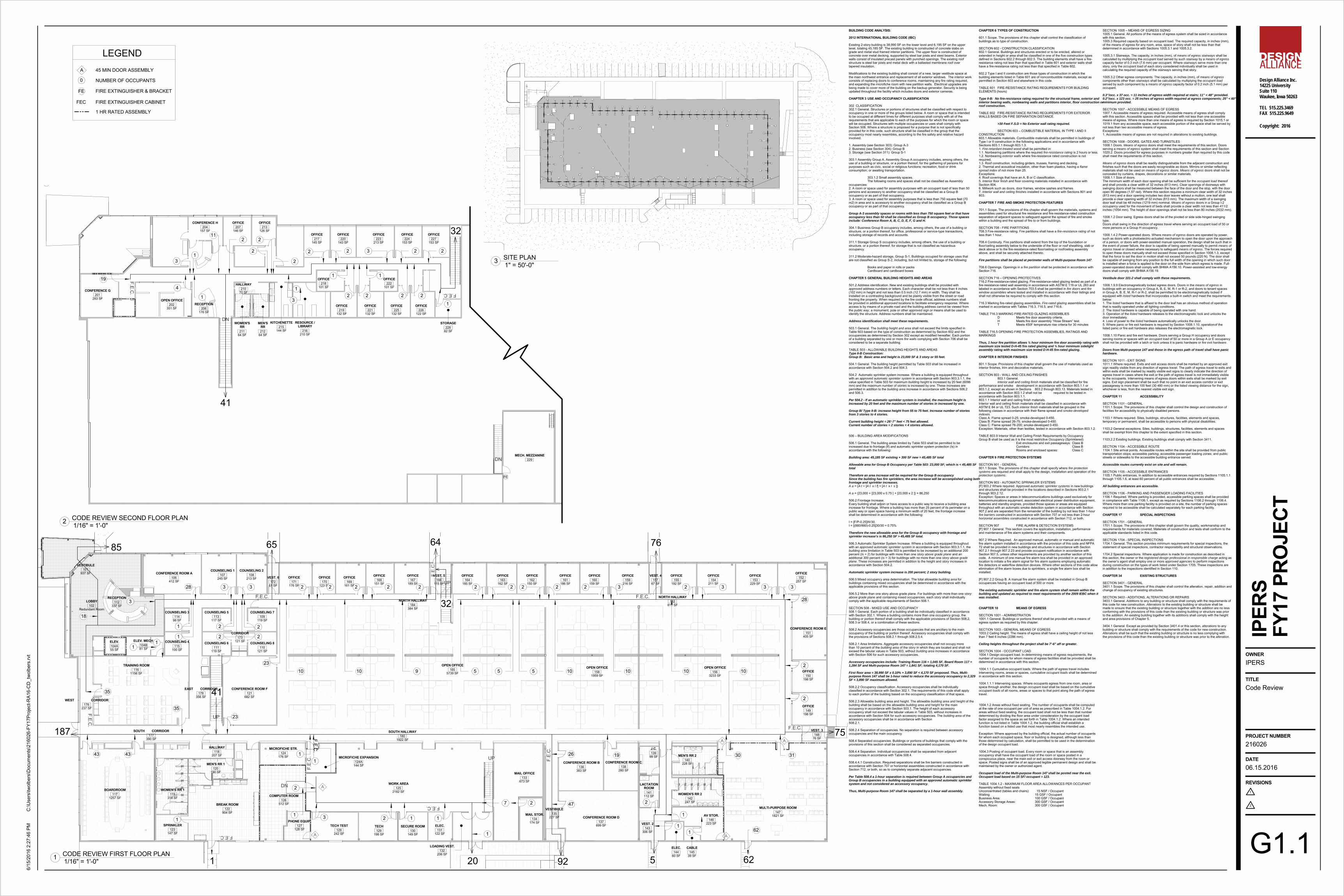
BUILDING CODE ANALYSIS:
2012 INTERNATIONAL BUILDING CODE (IBC)
Existing 2-story building is 38,990 SF on the lower level and 6,195 SF on the upperlevel, totaling 45,185 SF. The existing building is constructed of concrete slabs ongrade and metal stud framed interior partitions. The upper floor is constructed ofconcrete over metal decking, supported by steel bar joists and steel beams. Exteriorwalls consist of insulated precast panels with punched openings. The existing roofstructure is steel bar joists and metal deck with a ballasted membrane roof overtapered insulation.
Modifications to the existing building shall consist of a new, larger vestibule space atthe main northwest entrance and replacement of all exterior windows. The interior workconsists of replacing doors to conference rooms, maintaining any fire rating required,and expanding the microfiche room with new partition walls. Electrical upgrades arebeing made to cover more of the building on the backup generator. Security is beingupdated throughout the facility which includes doors and exterior cameras.
CHAPTER 3 USE AND OCCUPANCY CLASSIFICATION
302 CLASSIFICATION302.1 General. Structures or portions of structures shall be classified with respect tooccupancy in one or more of the groups listed below. A room or space that is intendedto be occupied at different times for different purposes shall comply with all of therequirements that are applicable to each of the purposes for which the room or spacewill be occupied. Structures with multiple occupancies or uses shall comply withSection 508. Where a structure is proposed for a purpose that is not specificallyprovided for in this code, such structure shall be classified in the group that theoccupancy most nearly resembles, according to the fire safety and relative hazardinvolved.
1. Assembly (see Section 303): Group A-32. Business (see Section 304): Group B3. Storage (see Section 311): Group S-1
303.1 Assembly Group A. Assembly Group A occupancy includes, among others, theuse of a building or structure, or a portion thereof, for the gathering of persons forpurposes such as civic, social or religious functions; recreation, food or drinkconsumption; or awaiting transportation.
303.1.2 Small assembly spaces.The following rooms and spaces shall not be classified as Assembly
occupancies:2. A room or space used for assembly purposes with an occupant load of less than 50persons and accessory to another occupancy shall be classified as a Group Boccupancy or as part of that occupancy.3. A room or space used for assembly purposes that is less than 750 square feet (70m2) in area and is accessory to another occupancy shall be classified as a Group Boccupancy or as part of that occupancy.
Group A-3 assembly spaces or rooms with less than 750 square feet or that haveoccupancy less than 50 shall be classified as Group B occupancy. Those spacesinclude: Conference Room A, B, C, D, E, F, G and H.
304.1 Business Group B occupancy includes, among others, the use of a building orstructure, or a portion thereof, for office, professional or service-type transactions,including storage of records and accounts.
311.1 Storage Group S occupancy includes, among others, the use of a building orstructure, or a portion thereof, for storage that is not classified as hazardousoccupancy.
311.2 Moderate-hazard storage, Group S-1. Buildings occupied for storage uses thatare not classified as Group S-2, including, but not limited to, storage of the following:
Books and paper in rolls or packsCardboard and cardboard boxes
CHAPTER 5 GENERAL BUILDING HEIGHTS AND AREAS
501.2 Address identification. New and existing buildings shall be provided withapproved address numbers or letters. Each character shall be not less than 4 inches(102 mm) in height and not less than 0.5 inch (12.7 mm) in width. They shall beinstalled on a contrasting background and be plainly visible from the street or roadfronting the property. When required by the fire code official, address numbers shallbe provided in additional approved locations to facilitate emergency response. Whereaccess is by means of a private road and the building address cannot be viewed fromthe public way, a monument, pole or other approved sign or means shall be used toidentify the structure. Address numbers shall be maintained.
Address identification shall meet these requirements.
503.1 General. The building height and area shall not exceed the limits specified inTable 503 based on the type of construction as determined by Section 602 and theoccupancies as determined by Section 302 except as modified hereafter. Each portionof a building separated by one or more fire walls complying with Section 706 shall beconsidered to be a separate building.
TABLE 503 - ALLOWABLE BUILDING HEIGHTS AND AREASType II-B Construction:Group B: Basic area and height is 23,000 SF & 3 story or 55 feet.
504.1 General. The building height permitted by Table 503 shall be increased inaccordance with Section 504.2 and 504.3.
504.2 Automatic sprinkler system increase. Where a building is equipped throughoutwith an approved automatic sprinkler system in accordance with Section 903.3.1.1, thevalue specified in Table 503 for maximum building height is increased by 20 feet (6096mm) and the maximum number of stories is increased by one. These increases arepermitted in addition to the building area increase in accordance with Sections 506.2and 506.3.
Per 504.2 - If an automatic sprinkler system is installed, the maximum height isincreased by 20 feet and the maximum number of stories in increased by one.
Group B/ Type II-B: increase height from 55 to 75 feet. Increase number of storiesfrom 3 stories to 4 stories.
Current building height = 26’-7” feet < 75 feet allowed.Current number of stories = 2 stories < 4 stories allowed.
506 – BUILDING AREA MODIFICATIONS
506.1 General. The building areas limited by Table 503 shall be permitted to beincreased due to frontage (If) and automatic sprinkler system protection (Is) inaccordance with the following:
Building area: 45,185 SF existing + 300 SF new = 45,485 SF total
Allowable area for Group B Occupancy per Table 503: 23,000 SF; which is < 45,485 SFtotal
Therefore an area increase will be required for the Group B occupancySince the building has fire sprinklers, the area increase will be accomplished using bothfrontage and sprinkler increases.A a = {A t + [A t x I f] + [A t x I s ]}
A a = {23,000 + [23,000 x 0.75 ] + [23,000 x 2 ]} = 86,250
506.2 Frontage Increase.Every building shall adjoin or have access to a public way to receive a building areaincrease for frontage. Where a building has more than 25 percent of its perimeter on apublic way or open space having a minimum width of 20 feet, the frontage increaseshall be determined in accordance with the following:
I = [F/P-0.25]W/30.I = [(880/880)-0.25]30/30 = 0.75%
Therefore the new allowable area for the Group B occupancy with frontage andsprinkler increase’s is 86,250 SF > 45,485 SF total.
506.3 Automatic Sprinkler System Increase. Where a building is equipped throughoutwith an approved automatic sprinkler system in accordance with Section 903.3.1.1, thebuilding area limitation in Table 503 is permitted to be increased by an additional 200percent (Is = 2) for buildings with more than one story above grade plane and anadditional 300 percent (Is = 3) for buildings with no more than one story above gradeplane. These increases are permitted in addition to the height and story increases inaccordance with Section 504.2.
Automatic sprinkler system increase is 200 percent; 2 story building.
506.5 Mixed occupancy area determination. The total allowable building area forbuildings containing mixed occupancies shall be determined in accordance with theapplicable provisions of this section.
506.5.2 More than one story above grade plane. For buildings with more than one storyabove grade plane and containing mixed occupancies, each story shall individuallycomply with the applicable requirements of Section 508.1.
SECTION 508 - MIXED USE AND OCCUPANCY508.1 General. Each portion of a building shall be individually classified in accordancewith Section 302.1. Where a building contains more than one occupancy group, thebuilding or portion thereof shall comply with the applicable provisions of Section 508.2,508.3 or 508.4, or a combination of these sections.
508.2 Accessory occupancies are those occupancies that are ancillary to the mainoccupancy of the building or portion thereof. Accessory occupancies shall comply withthe provisions of Sections 508.2.1 through 508.2.5.4.
508.2.1 Area limitations. Aggregate accessory occupancies shall not occupy morethan 10 percent of the building area of the story in which they are located and shall notexceed the tabular values in Table 503, without building area increases in accordancewith Section 506 for such accessory occupancies.
Accessory occupancies include: Training Room 116 = 1,045 SF, Board Room 117 =1,284 SF and Multi-purpose Room 147 = 1,841 SF; totaling 4,170 SF.
First floor area = 38,990 SF x 0.10% + 3,890 SF < 4,170 SF proposed. Thus, Multi-purpose Room 147 shall be 1-hour rated to reduce the accessory occupancy to 2,329SF < 3,890 SF maximum allowed.
508.2.2 Occupancy classification. Accessory occupancies shall be individuallyclassified in accordance with Section 302.1. The requirements of this code shall applyto each portion of the building based on the occupancy classification of that space.
508.2.3 Allowable building area and height. The allowable building area and height of thebuilding shall be based on the allowable building area and height for the mainoccupancy in accordance with Section 503.1. The height of each accessoryoccupancy shall not exceed the tabular values in Table 503, without increases inaccordance with Section 504 for such accessory occupancies. The building area of theaccessory occupancies shall be in accordance with Section508.2.1.
508.2.4 Separation of occupancies. No separation is required between accessoryoccupancies and the main occupancy.
508.4 Separated occupancies. Buildings or portions of buildings that comply with theprovisions of this section shall be considered as separated occupancies.
508.4.4 Separation. Individual occupancies shall be separated from adjacentoccupancies in accordance with Table 508.4.
508.4.4.1 Construction. Required separations shall be fire barriers constructed inaccordance with Section 707 or horizontal assemblies constructed in accordance withSection 712, or both, so as to completely separate adjacent occupancies.
Per Table 508.4 a 1-hour separation is required between Group A occupancies andGroup B occupancies in a building equipped with an approved automatic sprinklersystem and not considered an accessory occupancy.
Thus, Multi-purpose Room 147 shall be separated by a 1-hour wall assembly.
SECTION 1005 – MEANS OF EGRESS SIZING1005.1 General. All portions of the means of egress system shall be sized in accordancewith this section.1005.3 Required capacity based on occupant load. The required capacity, in inches (mm),of the means of egress for any room, area, space of story shall not be less than thatdetermined in accordance with Sections 1005.3.1 and 1005.3.2.
1005.3.1 Stairways. The capacity, in inches (mm), of means of egress stairways shall becalculated by multiplying the occupant load served by such stairway by a means of egresscapacity factor of 0.3 inch (7.6 mm) per occupant. Where stairways serve more than onestory, only the occupant load of each story considered individually shall be used incalculating the required capacity of the stairways serving that story.
1005.3.2 Other egress components. The capacity, in inches (mm), of means of egresscomponents other than stairways shall be calculated by multiplying the occupant loadserved by such component by a means of egress capacity factor of 0.2 inch (5.1 mm) peroccupant.
0.3”/occ. x 37 occ. = 11 inches of egress width required at stairs; 11” < 48” provided.0.2"/occ. x 123 occ. = 25 inches of egress width required at egress components; 25” < 60”minimum provided.
SECTION 1007 - ACCESSIBLE MEANS OF EGRESS1007.1 Accessible means of egress required. Accessible means of egress shall complywith this section. Accessible spaces shall be provided with not less than one accessiblemeans of egress. Where more than one means of egress is required by Section 1015.1 or1019.1 from any accessible space, each accessible portion of the space shall be served bynot less than two accessible means of egress.Exceptions:1. Accessible means of egress are not required in alterations to existing buildings.
SECTION 1008 - DOORS, GATES AND TURNSTILES1008.1 Doors. Means of egress doors shall meet the requirements of this section. Doorsserving a means of egress system shall meet the requirements of this section and Section1020.2. Doors provided for egress purposes in numbers greater than required by this codeshall meet the requirements of this section.
Means of egress doors shall be readily distinguishable from the adjacent construction andfinishes such that the doors are easily recognizable as doors. Mirrors or similar reflectingmaterials shall not be used on means of egress doors. Means of egress doors shall not beconcealed by curtains, drapes, decorations or similar materials.1008.1.1 Size of doors.The minimum width of each door opening shall be sufficient for the occupant load thereofand shall provide a clear width of 32 inches (813 mm). Clear openings of doorways withswinging doors shall be measured between the face of the door and the stop, with the dooropen 90 degrees (1.57 rad). Where this section requires a minimum clear width of 32 inches(813 mm) and a door opening includes two door leaves without a mullion, one leaf shallprovide a clear opening width of 32 inches (813 mm). The maximum width of a swingingdoor leaf shall be 48 inches (1219 mm) nominal. Means of egress doors in a Group I-2occupancy used for the movement of beds shall provide a clear width not less than 411/2inches (1054 mm). The height of door openings shall not be less than 80 inches (2032 mm).
1008.1.2 Door swing. Egress doors shall be of the pivoted or side side-hinged swingingtype.Doors shall swing in the direction of egress travel where serving an occupant load of 50 ormore persons or a Group H occupancy.
1008.1.4.2 Power-operated doors. Where means of egress doors are operated by power,such as doors with a photoelectric-actuated mechanism to open the door upon the approachof a person, or doors with power-assisted manual operation, the design shall be such that inthe event of power failure, the door is capable of being opened manually to permit means ofegress travel or closed where necessary to safeguard means of egress. The forces requiredto open these doors manually shall not exceed those specified in Section 1008.1.3, exceptthat the force to set the door in motion shall not exceed 50 pounds (220 N). The door shallbe capable of swinging from any position to the full width of the opening in which such dooris installed when a force is applied to the door on the side from which egress is made. Full-power-operated doors shall comply with BHMA A156.10. Power-assisted and low-energydoors shall comply with BHMA A156.19.
Vestibule door 101-2 shall comply with these requirements.
1008.1.9.9 Electromagnetically locked egress doors. Doors in the means of egress inbuildings with an occupancy in Group A, B, E, M, R-1 or R-2, and doors to tenant spacesin Group A, B, E, M, R-1 or R-2, shall be permitted to be electromagnetically locked ifequipped with listed hardware that incorporates a built-in switch and meet the requirementsbelow:1. The listed hardware that is affixed to the door leaf has an obvious method of operationthat is readily operated under all lighting conditions.2. The listed hardware is capable of being operated with one hand.3. Operation of the listed hardware releases to the electromagnetic lock and unlocks thedoor immediately.4. Loss of power to the listed hardware automatically unlocks the door.5. Where panic or fire exit hardware is required by Section 1008.1.10, operation of thelisted panic or fire exit hardware also releases the electromagnetic lock.
1008.1.10 Panic and fire exit hardware. Doors serving a Group H occupancy and doorsserving rooms or spaces with an occupant load of 50 or more in a Group A or E occupancyshall not be provided with a latch or lock unless it is panic hardware or fire exit hardware.
Doors from Multi-purpose 147 and those in the egress path of travel shall have panichardware.
SECTION 1011 - EXIT SIGNS1011.1 Where required. Exits and exit access doors shall be marked by an approved exitsign readily visible from any direction of egress travel. The path of egress travel to exits andwithin exits shall be marked by readily visible exit signs to clearly indicate the direction ofegress travel in cases where the exit or the path of egress travel is not immediately visibleto the occupants. Intervening means of egress doors within exits shall be marked by exitsigns. Exit sign placement shall be such that no point in an exit access corridor or exitpassageway is more than 100 feet (30 480 mm) or the listed viewing distance for the sign,whichever is less, from the nearest visible exit sign.
CHAPTER 11 ACCESSIBILITY
SECTION 1101 - GENERAL1101.1 Scope. The provisions of this chapter shall control the design and construction offacilities for accessibility to physically disabled persons.
1103.1 Where required. Sites, buildings, structures, facilities, elements and spaces,temporary or permanent, shall be accessible to persons with physical disabilities.
1103.2 General exceptions. Sites, buildings, structures, facilities, elements and spacesshall be exempt from this chapter to the extent specified in this section.
1103.2.2 Existing buildings. Existing buildings shall comply with Section 3411.
SECTION 1104 - ACCESSIBLE ROUTE1104.1 Site arrival points. Accessible routes within the site shall be provided from publictransportation stops; accessible parking; accessible passenger loading zones; and publicstreets or sidewalks to the accessible building entrance served.
Accessible routes currently exist on site and will remain.
SECTION 1105 - ACCESSIBLE ENTRANCES1105.1 Public entrances. In addition to accessible entrances required by Sections 1105.1.1through 1105.1.6, at least 60 percent of all public entrances shall be accessible.
All building entrances are accessible.
SECTION 1106 - PARKING AND PASSENGER LOADING FACILITIES1106.1 Required. Where parking is provided, accessible parking spaces shall be providedin compliance with Table 1106.1, except as required by Sections 1106.2 through 1106.4.Where more than one parking facility is provided on a site, the number of parking spacesrequired to be accessible shall be calculated separately for each parking facility.
CHAPTER 17 SPECIAL INSPECTIONS
SECTION 1701 - GENERAL1701.1 Scope. The provisions of this chapter shall govern the quality, workmanship andrequirements for materials covered. Materials of construction and tests shall conform to theapplicable standards listed in this code.
SECTION 1704 - SPECIAL INSPECTIONS1704.1 General. This section provides minimum requirements for special inspections, thestatement of special inspections, contractor responsibility and structural observations.
1704.2 Special inspections. Where application is made for construction as described inthis section, the owner or the registered design professional in responsible charge acting asthe owner’s agent shall employ one or more approved agencies to perform inspectionsduring construction on the types of work listed under Section 1705. These inspections arein addition to the inspections identified in Section 110.
CHAPTER 34 EXISTING STRUCTURES
SECTION 3401 - GENERAL3401.1 Scope. The provisions of this chapter shall control the alteration, repair, addition andchange of occupancy of existing structures.
SECTION 3403 - ADDITIONS, ALTERATIONS OR REPAIRS3403.1 General. Additions to any building or structure shall comply with the requirements ofthis code for new construction. Alterations to the existing building or structure shall bemade to ensure that the existing building or structure together with the addition are no lessconforming with the provisions of this code than the existing building or structure was priorto the addition. An existing building together with its additions shall comply with the heightand area provisions of Chapter 5.
3404.1 General. Except as provided by Section 3401.4 or this section, alterations to anybuilding or structure shall comply with the requirements of the code for new construction.Alterations shall be such that the existing building or structure is no less complying withthe provisions of this code than the existing building or structure was prior to the alteration.
CHAPTER 6 TYPES OF CONSTRUCTION
601.1 Scope. The provisions of this chapter shall control the classification ofbuildings as to type of construction.
SECTION 602 - CONSTRUCTION CLASSIFICATION602.1 General. Buildings and structures erected or to be erected, altered orextended in height or area shall be classified in one of the five construction typesdefined in Sections 602.2 through 602.5. The building elements shall have a fire-resistance rating not less than that specified in Table 601 and exterior walls shallhave a fire-resistance rating not less than that specified in Table 602.
602.2 Type I and II construction are those types of construction in which thebuilding elements listed in Table 601 are of noncombustible materials, except aspermitted in Section 603 and elsewhere in this code.
TABLE 601 FIRE-RESISTANCE RATING REQUIREMENTS FOR BUILDINGELEMENTS (hours)
Type II-B: No fire-resistance rating required for the structural frame, exterior andinterior bearing walls, nonbearing walls and partitions interior, floor construction orroof construction.
TABLE 602 FIRE-RESISTANCE RATING REQUIREMENTS FOR EXTERIORWALLS BASED ON FIRE SEPARATION DISTANCE.
>30 Feet F.S.D = No Exterior wall rating required.
SECTION 603 – COMBUSTIBLE MATERIAL IN TYPE I AND IICONSTRUCTION603.1 Allowable materials. Combustible materials shall be permitted in buildings ofType I or II construction in the following applications and in accordance withSections 603.1.1 through 603.1.3:1. Fire-retardant-treated wood shall be permitted in:1.1. Nonbearing partitions where the required fire-resistance rating is 2 hours or less.1.2. Nonbearing exterior walls where fire-resistance rated construction is notrequired.1.3. Roof construction, including girders, trusses, framing and decking.2. Thermal and acoustical insulation, other than foam plastics, having a flamespread index of not more than 25.Exceptions:4. Roof coverings that have an A, B or C classification.5. Interior floor finish and floor covering materials installed in accordance withSection 804.6. Millwork such as doors, door frames, window sashes and frames.7. Interior wall and ceiling finishes installed in accordance with Sections 801 and803.
CHAPTER 7 FIRE AND SMOKE PROTECTION FEATURES
701.1 Scope. The provisions of this chapter shall govern the materials, systems andassemblies used for structural fire resistance and fire-resistance-rated constructionseparation of adjacent spaces to safeguard against the spread of fire and smokewithin a building and the spread of fire to or from buildings.
SECTION 708 - FIRE PARTITIONS708.3 Fire-resistance rating. Fire partitions shall have a fire-resistance rating of notless than 1 hour.
708.4 Continuity. Fire partitions shall extend from the top of the foundation orfloor/ceiling assembly below to the underside of the floor or roof sheathing, slab ordeck above or to the fire-resistance-rated floor/ceiling or roof/ceiling assemblyabove, and shall be securely attached thereto.
Fire partitions shall be placed at perimeter walls of Multi-purpose Room 147.
708.6 Openings. Openings in a fire partition shall be protected in accordance withSection 716.
SECTION 716 – OPENING PROTECTIVES716.2 Fire-resistance-rated glazing. Fire-resistance-rated glazing tested as part of afire-resistance-rated wall assembly in accordance with ASTM E 119 or UL 263 andlabeled in accordance with Section 703.5 shall be permitted in fire doors and firewindow assemblies where tested and installed in accordance with their listings andshall not otherwise be required to comply with this section.
716.3 Marking fire-rated glazing assemblies. Fire-rated glazing assemblies shall bemarked in accordance with Tables 716.3, 716.5, and 716.6.
TABLE 716.3 MARKING FIRE-RATED GLAZING ASSEMBLIESD Meets fire door assembly criteria.H Meets fire door assembly “Hose Stream” test.T Meets 450F temperature rise criteria for 30 minutes
TABLE 716.5 OPENING FIRE PROTECTION ASSEMBLIES, RATINGS ANDMARKINGS
Thus, 1 hour fire partition allows ¾ hour minimum fire door assembly rating withmaximum size tested D-H-45 fire rated glazing and ¾ hour minimum sidelightassembly rating with maximum size tested D-H-45 fire-rated glazing.
CHAPTER 8 INTERIOR FINISHES
801.1 Scope. Provisions of this chapter shall govern the use of materials used asinterior finishes, trim and decorative materials.
SECTION 803 - WALL AND CEILING FINISHES803.1 General.Interior wall and ceiling finish materials shall be classified for fire
performance and smoke development in accordance with Section 803.1.1 or803.1.2, except as shown in Sections 803.2 through 803.13. Materials tested inaccordance with Section 803.1.2 shall not be required to be tested inaccordance with Section 803.1.1.803.1.1 Interior wall and ceiling finish materials.Interior wall and ceiling finish materials shall be classified in accordance withASTM E 84 or UL 723. Such interior finish materials shall be grouped in thefollowing classes in accordance with their flame spread and smoke-developedindexes.Class A: Flame spread 0-25; smoke-developed 0-450.Class B: Flame spread 26-75; smoke-developed 0-450.Class C: Flame spread 76-200; smoke-developed 0-450.Exception: Materials, other than textiles, tested in accordance with Section 803.1.2.
TABLE 803.9 Interior Wall and Ceiling Finish Requirements by OccupancyGroup B shall be used as it is the most restrictive Occupancy (Sprinklered)
Exit enclosures and exit passageways: Class BCorridors: Class BRooms and enclosed spaces: Class C
CHAPTER 9 FIRE PROTECTION SYSTEMS
SECTION 901 - GENERAL901.1 Scope. The provisions of this chapter shall specify where fire protectionsystems are required and shall apply to the design, installation and operation of fireprotection systems.
SECTION 903 - AUTOMATIC SPRINKLER SYSTEMS[F] 903.2 Where required. Approved automatic sprinkler systems in new buildingsand structures shall be provided in the locations described in Sections 903.2.1through 903.2.12.Exception: Spaces or areas in telecommunications buildings used exclusively fortelecommunications equipment, associated electrical power distribution equipment,batteries and standby engines, provided those spaces or areas are equippedthroughout with an automatic smoke detection system in accordance with Section907.2 and are separated from the remainder of the building by not less than 1-hourfire barriers constructed in accordance with Section 707 or not less than 2-hourhorizontal assemblies constructed in accordance with Section 712, or both.
SECTION 907 FIRE ALARM & DETECTION SYSTEMS[F] 907.1 General. This section covers the application, installation, performanceand maintenance of fire alarm systems and their components.
907.2 Where Required. An approved manual, automatic or manual and automaticfire alarm system installed in accordance with the provision of this code and NFPA72 shall be provided in new buildings and structures in accordance with Section907.2.1 through 907.2.23 and provide occupant notification in accordance withSection 907.5, unless other requirements are provided by another section of thiscode. A minimum of one manual fire alarm box shall be provided in an approvedlocation to initiate a fire alarm signal for fire alarm systems employing automaticfire detectors or waterflow detection devices. Where other sections of this code allowelimination of fire alarm boxes due to sprinklers, a single fire alarm box shall beinstalled.
[F] 907.2.2 Group B. A manual fire alarm system shall be installed in Group Boccupancies having an occupant load of 500 or more.
The existing automatic sprinkler and fire alarm system shall remain within thebuilding and updated as required to meet requirements of the 2009 IEBC when itwas installed.
CHAPTER 10 MEANS OF EGRESS
SECTION 1001 - ADMINISTRATION1001.1 General. Buildings or portions thereof shall be provided with a means ofegress system as required by this chapter.
SECTION 1003 - GENERAL MEANS OF EGRESS1003.2 Ceiling height. The means of egress shall have a ceiling height of not lessthan 7 feet 6 inches (2286 mm).
Ceiling heights throughout the project shall be 7’-6” aff or greater.
SECTION 1004 - OCCUPANT LOAD1004.1 Design occupant load. In determining means of egress requirements, thenumber of occupants for whom means of egress facilities shall be provided shall bedetermined in accordance with this section.
1004.1.1 Cumulative occupant loads. Where the path of egress travel includesintervening rooms, areas or spaces, cumulative occupant loads shall be determinedin accordance with this section.
1004.1.1.1 Intervening spaces. Where occupants egress from one room, area orspace through another, the design occupant load shall be based on the cumulativeoccupant loads of all rooms, areas or spaces to that point along the path of egresstravel.
1004.1.2 Areas without fixed seating. The number of occupants shall be computedat the rate of one occupant per unit of area as prescribed in Table 1004.1.2. Forareas without fixed seating, the occupant load shall not be less than that numberdetermined by dividing the floor area under consideration by the occupant loadfactor assigned to the space as set forth in Table 1004.1.2. Where an intendedfunction is not listed in Table 1004.1.2, the building official shall establish afunction based on a listed use that most nearly resembles the intended use.
Exception: Where approved by the building official, the actual number of occupantsfor whom each occupied space, floor or building is designed, although less thanthose determined by calculation, shall be permitted to be used in the determinationof the design occupant load.
1004.3 Posting of occupant load. Every room or space that is an assemblyoccupancy shall have the occupant load of the room or space posted in aconspicuous place, near the main exit or exit access doorway from the room orspace. Posted signs shall be of an approved legible permanent design and shall bemaintained by the owner or authorized agent.
Occupant load of the Multi-purpose Room 147 shall be posted near the exit.Occupant load based on 15 SF/ occupant = 123.
TABLE 1004.1.2 - MAXIMUM FLOOR AREA ALLOWANCES PER OCCUPANTAssembly without fixed seatsUnconcentrated (tables and chairs): 15 NSF / OccupantWaiting: 15 GSF / OccupantBusiness Area: 100 GSF / OccupantAccessory Storage Areas: 300 GSF / OccupantMech. Room: 300 GSF / Occupant
1" = 50'-0"3 SITE PLAN
UP
UP
DN
UP
REF.
REF.
F.E.C.
F.E.C.
F.E.
C.
F.E.C.
A5.1 4
COMPUTER ROOM126
132-
2
BOARDROOM117
SPRINKLER123
BREAK ROOM122
WOMEN'S RR 1119
MEN'S RR 1120
HALLWAY118
LOBBY102
CONFERENCEROOM A
106
COUNSELING 1107
COUNSELING 2108 VEST. 6
172 OFFICE171
OFFICE170
OFFICE169
OFFICE168
OFFICE167
VEST. 5166
OFFICE164
LOADING VEST.132ELEC.
131SECURE ROOM
130TECH129
TECH TEST128
PHONE EQUIP.127
WORK AREA125
MICROFICHE STR.124
OPEN OFFICE165
CONFERENCEROOM F
121
COUNSELING 8110
COUNSELING 7109
COUNSELING 5113
COUNSELING 6111
TRAINING ROOM116
ELEV.104A
ELEV. MECH.104B
COUNSELING 4115
COUNSELING 3114
AV105
122
132-1
166
172
116
121
RECEPTION112
CORRIDOR173
NORTHCORRIDOR
174
COAT175
WESTCORRIDOR
176
SOUTHCORRIDOR
177
EASTCORRIDOR
178
STAIR A179
SOUTH HALLWAY180
STAIR B183
NORTH HALLWAY184
FM
A5.1
5
124A
MICROFICHEEXPANSION
124A
101-2
A1.35
CA
1
2
VESTIBULE101 101-310
1-1
A1.315' - 0"
8' -
0"
5' - 0" 14' - 3"
14' -
3"
5' -
9"
CONCRETE STOOP,SEE STRUCT. DWGS.
CONC. STOOP,SEE STRUCT. DWGS.
10' - 8 1/4" 10' - 8 1/4"B
REMOVE AND REPLACE EXISTINGFLAGPOLE, SEE SPECIFICATION
NEW 4" CONCRETE SIDEWALK
2A7.2
12
A4.1
177
REMOVE EXISTING GLASS BLOCKAT CANOPY STRUCTURE. PREPAREAREA FOR NEW ALUMINUM FRAMING.PROVIDE "TYPE I" ALUMINUM FRAMEAND GLAZING IN EXISTING STEEL FRAMEOPENING
1.6 1.1 1.1
1.1A 1.1A
1.6
1.1A
1.1
1.1 1.1 1.1
1.3
1.3
1.3
1.31.3
1.7
1.7
1.31.3
1.41.5
Design Alliance Inc.14225 UniversitySuite 110Waukee, Iowa 50263
TEL 515.225.3469FAX 515.225.9649
1
2
Copyright: 2016
OWNER
TITLE
PROJECT NUMBER
DATE
REVISIONS
C:\U
sers
\twol
bers
\Doc
umen
ts\2
1602
6-FY
17Pr
ojec
t-RA1
6-C
D_t
wol
bers
.rvt
6/15
/201
6 2:
27:0
4 PM
IPER
S
A1.1
06.15.2016
216026
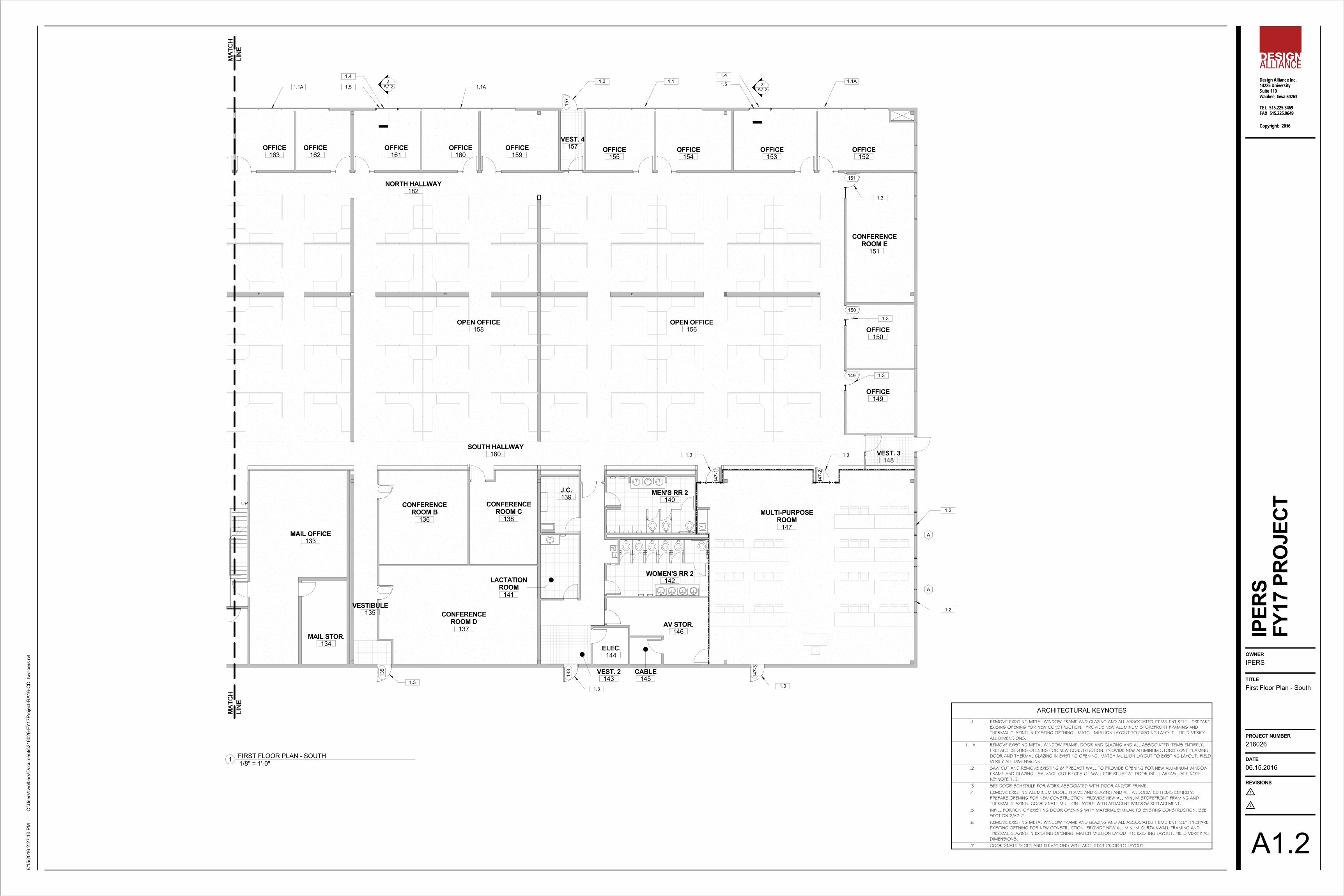
First Floor Plan - North
IPERS
FY17
PRO
JECT
1/8" = 1'-0"1 FIRST FLOOR PLAN - NORTH
ARCHITECTURAL KEYNOTES1.1 REMOVE EXISTING METAL WINDOW FRAME AND GLAZING AND ALL ASSOCIATED ITEMS ENTIRELY. PREPARE
EXISING OPENING FOR NEW CONSTRUCTION. PROVIDE NEW ALUMINUM STOREFRONT FRAMING ANDTHERMAL GLAZING IN EXISTING OPENING. MATCH MULLION LAYOUT TO EXISTING LAYOUT. FIELD VERIFYALL DIMENSIONS.
1.1A REMOVE EXISTING METAL WINDOW FRAME, DOOR AND GLAZING AND ALL ASSOCIATED ITEMS ENTIRELY.PREPARE EXISTING OPENING FOR NEW CONSTRUCTION. PROVIDE NEW ALUMINUM STOREFRONT FRAMING,DOOR AND THERMAL GLAZING IN EXISTING OPENING. MATCH MULLION LAYOUT TO EXISTING LAYOUT. FIELDVERIFY ALL DIMENSIONS.
1.2 SAW CUT AND REMOVE EXISTING 8" PRECAST WALL TO PROVIDE OPENING FOR NEW ALUMINUM WINDOWFRAME AND GLAZING. SALVAGE CUT PIECES OF WALL FOR REUSE AT DOOR INFILL AREAS. SEE NOTEKEYNOTE 1.5.
1.3 SEE DOOR SCHEDULE FOR WORK ASSOCIATED WITH DOOR AND/OR FRAME.1.4 REMOVE EXISTING ALUMINUM DOOR, FRAME AND GLAZING AND ALL ASSOCIATED ITEMS ENTIRELY.
PREPARE OPENING FOR NEW CONSTRUCTION. PROVIDE NEW ALUMINUM STOREFRONT FRAMING ANDTHERMAL GLAZING. COORDINATE MULLION LAYOUT WITH ADJACENT WINDOW REPLACEMENT.
1.5 INFILL PORTION OF EXISTING DOOR OPENING WITH MATERIAL SIMILAR TO EXISTING CONSTRUCTION. SEESECTION 2/A7.2.
1.6 REMOVE EXISTING METAL WINDOW FRAME AND GLAZING AND ALL ASSOCIATED ITEMS ENTIRELY. PREPAREEXISTING OPENING FOR NEW CONSTRUCTION. PROVIDE NEW ALUMINUM CURTAINWALL FRAMING ANDTHERMAL GLAZING IN EXISTING OPENING. MATCH MULLION LAYOUT TO EXISTING LAYOUT. FIELD VERIFY ALLDIMENSIONS.
1.7 COORDINATE SLOPE AND ELEVATIONS WITH ARCHITECT PRIOR TO LAYOUT
UP
147-
3
143
135
CONFERENCEROOM D
137
CONFERENCEROOM B
136
OFFICE163
OFFICE162
OFFICE161
OFFICE160
OFFICE159
VEST. 4157 OFFICE
155OFFICE
154OFFICE
153OFFICE
152
CONFERENCEROOM E
151
OFFICE150
OFFICE149
VEST. 3148
MULTI-PURPOSEROOM
147
WOMEN'S RR 2142
AV STOR.146
CABLE145
ELEC.144
VEST. 2143
LACTATIONROOM
141
MEN'S RR 2140
J.C.139
CONFERENCEROOM C
138
MAIL STOR.134
VESTIBULE135
MAIL OFFICE133
OPEN OFFICE158
OPEN OFFICE156
157
147-
2
NORTH HALLWAY182
SOUTH HALLWAY180
147-
1
151
149
150
A
A
2A7.2
2A7.21.1A 1.1A
1.4
1.51.3 1.1 1.1A
1.4
1.5
1.3
1.3
1.3
1.31.3
1.31.31.3
1.2
1.2
Design Alliance Inc.14225 UniversitySuite 110Waukee, Iowa 50263
TEL 515.225.3469FAX 515.225.9649
1
2
Copyright: 2016
OWNER
TITLE
PROJECT NUMBER
DATE
REVISIONS
C:\U
sers
\twol
bers
\Doc
umen
ts\2
1602
6-FY
17Pr
ojec
t-RA1
6-C
D_t
wol
bers
.rvt
6/15
/201
6 2:
27:1
0 PM
IPER
S
A1.2
06.15.2016
216026
First Floor Plan - South
IPERS
FY17
PRO
JECT
1/8" = 1'-0"1 FIRST FLOOR PLAN - SOUTH
ARCHITECTURAL KEYNOTES1.1 REMOVE EXISTING METAL WINDOW FRAME AND GLAZING AND ALL ASSOCIATED ITEMS ENTIRELY. PREPARE
EXISING OPENING FOR NEW CONSTRUCTION. PROVIDE NEW ALUMINUM STOREFRONT FRAMING ANDTHERMAL GLAZING IN EXISTING OPENING. MATCH MULLION LAYOUT TO EXISTING LAYOUT. FIELD VERIFYALL DIMENSIONS.
1.1A REMOVE EXISTING METAL WINDOW FRAME, DOOR AND GLAZING AND ALL ASSOCIATED ITEMS ENTIRELY.PREPARE EXISTING OPENING FOR NEW CONSTRUCTION. PROVIDE NEW ALUMINUM STOREFRONT FRAMING,DOOR AND THERMAL GLAZING IN EXISTING OPENING. MATCH MULLION LAYOUT TO EXISTING LAYOUT. FIELDVERIFY ALL DIMENSIONS.
1.2 SAW CUT AND REMOVE EXISTING 8" PRECAST WALL TO PROVIDE OPENING FOR NEW ALUMINUM WINDOWFRAME AND GLAZING. SALVAGE CUT PIECES OF WALL FOR REUSE AT DOOR INFILL AREAS. SEE NOTEKEYNOTE 1.5.
1.3 SEE DOOR SCHEDULE FOR WORK ASSOCIATED WITH DOOR AND/OR FRAME.1.4 REMOVE EXISTING ALUMINUM DOOR, FRAME AND GLAZING AND ALL ASSOCIATED ITEMS ENTIRELY.
PREPARE OPENING FOR NEW CONSTRUCTION. PROVIDE NEW ALUMINUM STOREFRONT FRAMING ANDTHERMAL GLAZING. COORDINATE MULLION LAYOUT WITH ADJACENT WINDOW REPLACEMENT.
1.5 INFILL PORTION OF EXISTING DOOR OPENING WITH MATERIAL SIMILAR TO EXISTING CONSTRUCTION. SEESECTION 2/A7.2.
1.6 REMOVE EXISTING METAL WINDOW FRAME AND GLAZING AND ALL ASSOCIATED ITEMS ENTIRELY. PREPAREEXISTING OPENING FOR NEW CONSTRUCTION. PROVIDE NEW ALUMINUM CURTAINWALL FRAMING ANDTHERMAL GLAZING IN EXISTING OPENING. MATCH MULLION LAYOUT TO EXISTING LAYOUT. FIELD VERIFY ALLDIMENSIONS.
1.7 COORDINATE SLOPE AND ELEVATIONS WITH ARCHITECT PRIOR TO LAYOUT
DN
LOBBY102
VESTIBULE101
CA
1
2
2A7.1
1A7.2
1A7.1
7 1/2" 21' - 4 1/2" 7 1/2"
7 1
3/1
6"
16' -
5 3
/16"
7 1
3/1
6"
5' - 0 1/4" +/- 7 1/2" 11' - 4 1/4"
7 3
/16"
5' -
1 9
/16"
2' -
1 3
/4"
2' - 1 3/4"
101-
1
101-2
101-3
17' -
8 1
3/1
6"
22' - 7 1/2"
5' -
8 1
3/1
6"
A4.16
B
PATCH IN TILE FLOORINGIN THIS AREA WHERE WALLWAS REMOVED
8' -
0"
8' -
6"
1' - 6" 1' - 6" EQ. EQ. 1' - 6"
6' -
8"
RELOCATED CONC.BENCH, PROVIDEFOOTING AS REQ'D.
1' -
6"
RELOCATED CONC.BENCH, PROVIDEFOOTING AS REQ'D.
RELOCATED CONC.BENCH, PROVIDEFOOTING AS REQ'D.
FEATHER REED GRASS (5)
FEATHER REED GRASS (12)
RELOCATED CONC. SPHERES,PROVIDE 18" DIA CONC.FOUNDATION, TYP.
3" SHREDDED HARDWOOD MULCH, TYP.
3" SPADE CUT EDGE, TYP.EXISTING PLANTING BED
EXISTING PLANTING BED
EXISTING TREE TO REMAIN
B
ALIG
N W/ E
DGES
OF E
XISTIN
G OPE
ING
10"B
ALIGN NEW CORNERWITH EDGE OF EXISTINGACCESS PANEL TOREMAIN, FIELD VERIFY
CONFERENCE G201
OPEN OFFICE202
CONFERENCE H204
RECEPTION206
OPEN TOBELOW
1.24' - 6"
B
B
MECHANICAL CHASE,CUT & FIT EXISTINGDESK AS REQ'D FORNEW CHASE
B
B
124A
EXISTING CONCRETEFLOOR
MICROFICHEEXPANSION
124A
P.LAM C-TOP ANDBRACKETS
A A
A
B 12' -
8 1
/2"
12' - 9 1/2"
FIELD VERIFY
5' - 2 1/4" 7A1.3
2' - 1"
RELOCATE EXISTING FIREEXTINGUISHER CABINET
EQ. 2' - 6" 2' - 6" EQ.
9' -
0"
11 1
/2"
1/2
"
2' -
10"
4' -
0"
3' -
0"
B
5' - 0"
4" X 4" STEEL SECURITY MESH OVERDOUBLE METAL STUD CHANNELS SECUREDTOGETHER WITH METAL PAN HEAD SCREWS@ 8" O.C., SECURE GRID TO CHANNELS W/CLIPS @ 12" O.C.
OPEN CEILING GRID
PLAM COUNTERTOP AND BRACKETS
HOLLOW METAL BORROW LIGHT AND GLAZING
LOBBY102
RECEPTION112
CA
1
2
B
REMOVE EXISTING GYP. BD. CEILING AND ASSOCIATEDITEMS ENTIRELY IN THIS AREA. EXTEND EXISTING ACOUTICALCEILING GRID AND TILE WITH LIKE MATERIALS. EXTEND GYP. BD.AND FURRING AT EXTERIOR WALLS FROM EXISTING CEILINGHEIGHT TO NEW CEILING HEIGHT AS REQUIRED. MATCH ADJACENT SURFACES.
ARCHITECTURAL ROOF DECKING, PAINTSEE STRUCT. DWGS.
STEEL ROOF RIB, PAINT, TYP.SEE STRUCT. DWGS.
FACE-FASTENED ACM PANELS
6" X 6" CONDUCTOR HEAD& DOWNSPOUT
3" X 3" GUTTER
3" X 3" GUTTER
6" X 6" CONDUCTOR HEAD& DOWNSPOUT
HVAC UNIT,SEE MECH. DWGS.
102
LOBBY
103
RECEPTION
104
TOILET
107
OFFICE
105
ELEV. EQUIPELEV.
D.1D.2
D.2
D.2
D.2
D.2
D.2
D.3
D.3
D.3
D.3
D.5
D.4
D.7 D.6
D.7
D.6
D.8
D.7D.9
D.9
D.4
D.4
D.11
D.11
D.10
OPEN CEILING GRID@ 9'-0" AFF
4" X 4" STEEL SECURITYGRID @ 10'-0" AFF
2X4 TROFFER,SEE ELECT.
EXISTING LIGHT,ABOVE
Design Alliance Inc.14225 UniversitySuite 110Waukee, Iowa 50263
TEL 515.225.3469FAX 515.225.9649
1
2
Copyright: 2016
OWNER
TITLE
PROJECT NUMBER
DATE
REVISIONS
C:\U
sers
\twol
bers
\Doc
umen
ts\2
1602
6-FY
17Pr
ojec
t-RA1
6-C
D_t
wol
bers
.rvt
6/15
/201
6 2:
27:1
8 PM
IPER
S
A1.3
06.15.2016
216026
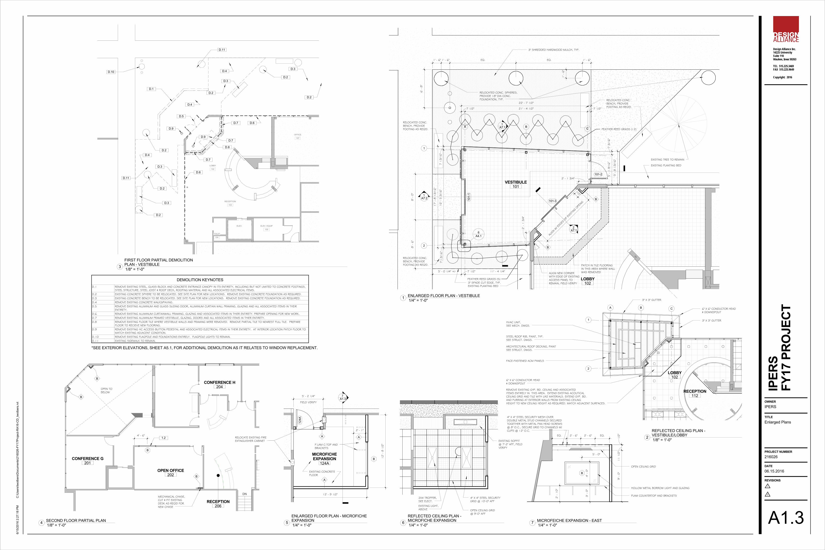
Enlarged Plans
IPERS
FY17
PRO
JECT
1/4" = 1'-0"1 ENLARGED FLOOR PLAN - VESTIBULE
1/8" = 1'-0"4 SECOND FLOOR PARTIAL PLAN 1/4" = 1'-0"5ENLARGED FLOOR PLAN - MICROFICHEEXPANSION
1/4" = 1'-0"7 MICROFEICHE EXPANSION - EAST
1/8" = 1'-0"2REFLECTED CEILING PLAN -VESTIBULE/LOBBY
1/8" = 1'-0"3FIRST FLOOR PARTIAL DEMOLITIONPLAN - VESTIBULE
DEMOLITION KEYNOTESD.1 REMOVE EXISTING STEEL, GLASS BLOCK AND CONCRETE ENTRANCE CANOPY IN ITS ENTIRETY, INCLUDING BUT NOT LIMITED TO CONCRETE FOOTINGS,
STEEL STRUCTURE, STEEL JOIST & ROOF DECK, ROOFING MATERIAL AND ALL ASSOCIATED ELECTRICAL ITEMS.D.2 EXISTING CONCRETE SPHERE TO BE RELOCATED. SEE SITE PLAN FOR NEW LOCATIONS. REMOVE EXISTING CONCRETE FOUNDATION AS REQUIRED.D.3 EXISTING CONCRETE BENCH TO BE RELOCATED. SEE SITE PLAN FOR NEW LOCATIONS. REMOVE EXISTING CONCRETE FOUNDATION AS REQUIRED.D.4 REMOVE EXISTING CONCRETE WALKS/PAVING.D.5 REMOVE EXISTING ALUMINUM AND GLASS SLIDING DOOR, ALUMINUM CURTAIN WALL FRAMING, GLAZING AND ALL ASSOCIATED ITEMS IN THEIR
ENTIRETY.D.6 REMOVE EXISTING ALUMINUM CURTAINWALL FRAMING, GLAZING AND ASSOCIATED ITEMS IN THIER ENTIRETY. PREPARE OPENING FOR NEW WORK.D.7 REMOVE EXISTING ALUMINUM FRAMED VESTIBULE, GLAZING, DOORS AND ALL ASSOCIATED ITEMS IN THIER ENTIRETY.D.8 REMOVE EXISTING FLOOR TILE WHERE VESTIBULE WALLS AND FRAMING WERE REMOVED. REMOVE PARTIAL TILE TO NEAREST FULL TILE. PREPARE
FLOOR TO RECIEVE NEW FLOORING.D.9 REMOVE EXISTING HC ACCESS BUTTON PEDESTAL AND ASSOCIATED ELECTRICAL ITEMS IN THEIR ENTIRETY. AT INTERIOR LOCATION PATCH FLOOR TO
MATCH EXISTING ADJACENT CONDITION.D.10 REMOVE EXISTING FLAGPOLE AND FOUNDATIONS ENTIRELY. FLAGPOLE LIGHTS TO REMAIN.D.11 EXISTING SIDEWALK TO REMAIN.
*SEE EXTERIOR ELEVATIONS, SHEET A5.1, FOR ADDITIONAL DEMOLITION AS IT RELATES TO WINDOW REPLACEMENT.
1/4" = 1'-0"6REFLECTED CEILING PLAN -MICROFICHE EXPANSION
EXISTING SOFFIT@ 7'-2" AFF, FIELDVERIFY
SEESCHED.
SEE
SC
HED
.
F FG N
10"
6"
6"6"
SEESCHED.
SEE
SC
HED
.
3' -
0"
6"
6" 6"
SEESCHED.
SEE
SC
HED
.
EG-1 @ EXTERIORIG-1 @ INTERIOR, NON-RATEDIG-2 @ INTERIOR, RATED
3 5/8" 5/8"METAL STUDS w/BATT INSULATION
5/8" GYP. BD.- EACH SIDE
HEADER - SEESTRUCT. DWGS. PROVIDE SEALANT AROUND
ENTIRE PERIMETER OFFRAME (TYP.)
H.M. DOOR FRAME- SEE SCHEDULE
SIDELIGHT
5 3/4"
5/8"
4 7/8"
GROUT VOID FULL
WOOD BLOCKING AS REQ'D.
EXISTING INSULATION
SEALANT CONT., TYP.
SHIMS AS REQ'D.
ALUMINUM WINDOW W/THERMAL GLAZING
EXISTING METAL STUDFURRING & GYP. BD.CUT TO CREATE NEWWINDOW OPENING.PATCH IN NEW RETURNW/ SIMILAR MATERIALS
GROUT VOID FULL
WOOD BLOCKING AS REQ'D.
EXISTING INSULATION
SEALANT CONT., TYP.
SHIMS AS REQ'D.
ALUMINUM WINDOW W/THERMAL GLAZING
EXISTING METAL STUDFURRING & GYP. BD.CUT TO CREATE NEWWINDOW OPENING.
1/2" SOLID SURFACESILL OVER 3/4" PLYWOOD
1 3
/8"
7' - 2"
5 1
/2"
4' -
8"
1 1
/2"
2' - 6"
SAW CUT & REMOVE PORTION OFEXISTING CONCRETE PANEL, SEEDEMO & STRUCT. DWGS.
EXISTING 2" METAL FURRING& 5/8" GYP. BD. TO REMAIN.PATCH BACK TO CONC. ATNEW OPENINGS, TYP.
3"4 1/2"NEW ALUMINUM WINDOW& GLAZING. SEE WINDOWDETAILS.
EXISTING 8" CONCRETE PANELTO REMAIN, VERIFY EXACTTHICKNESS OF CONCRETE &INSULATION WYTHES
REMOVE INSULATION TO DEPTHSHOWN. INSTALL BLOCKING& GROUT VOID FULL
A4.19
9
A4.1
A4.110
2' -
6"
4' -
8"
10' - 0"
3' -
2"
4' -
0"
6' - 0"
AB
9
A4.1
9
A4.1
10
A4.1
2" 4' - 9" 2" 4' - 9" 2"
2"
4' -
4"
2"
2" 5' - 8" 2"
2"
3' -
8"
2"
3
A4.1
3
A4.1
3
A4.1
EG-1
EG-1 IG
-1
5/8" TYPE "X" GYP.BOARD - EACH SIDE -PAINT
3 5/8" METALSTUDS @ 16" O.C.
4 7/8" NOM.
3" SOUNDATTENUATIONBLANKET
A
METAL RUNNER SET INBEAD OF ACOUSTICALMASTIC
5/8" TYPE "X" GYP.BOARD - ONE SIDE- PAINT
2 1/2" METALSTUDS @ 16" O.C.
B
3 1/8" NOM.
A
STEEL TUBE,SEE STRUCT. DWGS
2"2"1"1/4"
4 1
/2" 1/4" BENT STEEL
MOUNTING PLATEACROSS TOP OFSLIDING DOOR,WELD TO TUBE
SLIDING DOORHEAD
ALUMINUM STOREFRONTFRAMING AND 1"THERMAL GLAZING
A
2
7 1/2"
7 1
/2"
STEEL TUBE COLUMN,SEE STRUCT. DWGS.
ALUMINUM STOREFRONTAND 1" THERMAL GLAZING
CUSTOM FABRICATEDALUMINUM CORNER, MATCHSTOREFRONT FINISH
FILL VOID WITHBATT INSULATION
ALUMINUM STOREFRONTAND 1" THERMAL GLAZING
3' - 0"
6' -
8"
A
6' -
8"
B
6' - 0"
6' -
8"
C
4' - 6"
2"
SEESCHED.
2"
1' - 0"
2"
16' - 11 1/2"
4 1/2"2"
1' - 10 3/4"
2"
3' - 1"
2"
2' - 11"
2"
2' - 11"
2"
3' - 1"
2"
1' - 10 3/4"
2"
4 1/2"2"
7' -
9"
2"
4' -
4 5
/8"
12' -
5 5
/8"
11 5
/16
"
F
4 1/2"2"
4' - 1 5/16"2"
4' - 1 5/16"2"4' - 1 5/16"
2"4' - 1 5/16"
2"4' - 1 5/16"
2"4 1/2"
SEESCHED.
SEE
SC
HED
.
2"8"
2"3' - 0"
2"
1' - 0 1/2"
2"4 1/2"
5' - 4 1/2"
11' -
3 5
/16"
2"
7' -
9"
2"
3' -
2 5
/16"
SEESCHED.
SEE
SC
HED
.12' -
4 7
/8"
11' -
2 3
/16"
2"
7' -
9"
2"
12' -
4 1
/2"
12' -
4 1
/2"
2"
7' -
9"
2"
4' -
3 1
/2"
11' -
8 3
/4"
21' - 6 5/8" 11' - 7 1/4"
4 1/2"2"
3' - 7 3/4"2"
3' - 7 3/4"2"
3' - 7 3/4"2"
12' -
0"
2' -
0 1
/2"
5' -
7"
2 1
/2"
7' -
8 1
/2"
2 1
/2"
3' -
8"
2 1
/2"
9' - 11"
2 1/2"
1' - 6 1/2"
2 1/2"
2' - 10 3/4"
2 1/2"
2' - 10 3/4"
2 1/2"
1' - 6 1/2"
2 1/2"
2 1
/2"
5' -
2"
2 1
/2"
SEE
SC
HED
.
SEESCHED.
D E G H
4
A7.2
3
A7.1
3
A7.2
3
A7.1
6
A4.1
6
A4.16
A4.1
5
A4.16
A4.16
A4.1SIM
6
A4.1
SIM
7
A4.17
A4.17
A4.1
7
A4.1
8
A4.1
8
A4.1
SIM
EG-1
EG-1
EG-1
EG-1
EG-1
EG-1
EG-1
EG-1
EG-1
EG-1
EG-1
EG-1
EG-1
EG-1
EG-1
EG-1
EG-1
EG-1
EG-1
EG-1
EG-1
EG-1
EG-1
EG-1
EG-1
EG-1
EG-1
EG-1
EG-1
EG-1
EG-1
EG-1
EG-1
EG-1
EG-1
IG-1
IG-1
IG-1
IG-1
IG-1
IG-1
IG-1
1
A4.1
2
A4.1
3
A4.1
4
A4.1
4
A7.1
11
A4.111
A4.1SIM
SIM
11
A4.1
12
A4.1
I
9' - 0"
2" 2' - 9"
2"
2' - 10"
2"
2' - 9" 2"
9' -
0"
2"
7' -
0"
2"
1' -
6"
2"
EG-2
EG-2
EG-2
EG-2
EG-2
EG-2
REPEATING "IPERS" LOGO4" VINYL SIGNAGE, TYP.
TYP.
3' -
11"
ALUMINUM STOREFRONTAND 1" THERMAL GLAZINGAND SUB-SILL FLASHING
CONCRETE FLOOR SLAB,SEE STRUCT. DWGS
SHIMS, BACKER ROD ANDSEALANT, CONT., TYP.
TILE FLOORING
SEALANT, CONT.
ALUMINUM STOREFRONTAND 1" THERMAL GLAZING
EXISTING STRUCTURE TO REMAIN
SHIMS, BACKER ROD ANDSEALANT, CONT., TYP.
METAL STUDS W/BATT INSUL.
5/8" GYP. BD.EACH SIDE
HEADER, SEESTRUCT. DWGS.
PROVIDE SEALANT AROUNDENTIRE PERIMETER OFFRAME (TYP.)
H.M. DOOR FRAME - SEESCHEDULE
DOOR - SEESCHEDULE
2"
T.O. DOOR FRAMEEL. +7'-2"
5 3/4"
3 5/8"
5/8" 3 5/8" 5/8"
METAL STUDS w/BATT INSULATION
5/8" GYP. BD. -EACHSIDE
DOUBLE STUD@ JAMB, TYP.
PROVIDE SEALANT AROUNDENTIRE PERIMETER OFFRAME (TYP.)
H.M. DOOR FRAME -SEE SCHEDULE
H.M. DOOR - SEESCHEDULE
4 7/8"
5 3/4"
ALUMINUM SLIDING DOOR
ALUMINUM SLIDING DOORTRACK/FRAME
ALUMINUM STOREFRONTAND 1" THERMAL GLAZING
4"
4 1
/2"
ALUMINUM SLIDING DOORTRACK/FRAME
ALUMINUM CURTAIN WALLAND 1" THERMAL GLAZING
1/2" 7 1/2" 2 5/8"
EXISTING PRECAST TO REMAIN
SHIMS, BACKER ROD &SEALANT, CONT., TYP.
5/8" GYP. BD.
2" METAL STUD FURRING& BATT INSULATION
ALUMINUM CURTAIN WALLAND 1" THERMAL GLAZING
EXISTING FLOOR TO REMAIN
SHIMS, BACKER ROD &SEALANT, CONT., TYP. TILE FLOORING
SEALANT, CONT.
GLAZING LEGENDEG-1 1" THERMALEG-2 1/4" TEMPERED
IG-1 1/4" TEMPEREDIG-2 5/16" 45 MIN. CERAMIC GLAZING
Design Alliance Inc.14225 UniversitySuite 110Waukee, Iowa 50263
TEL 515.225.3469FAX 515.225.9649
1
2
Copyright: 2016
OWNER
TITLE
PROJECT NUMBER
DATE
REVISIONS
C:\U
sers
\twol
bers
\Doc
umen
ts\2
1602
6-FY
17Pr
ojec
t-RA1
6-C
D_t
wol
bers
.rvt
6/15
/201
6 2:
27:2
3 PM
IPER
S
A4.1
06.15.2016
216026
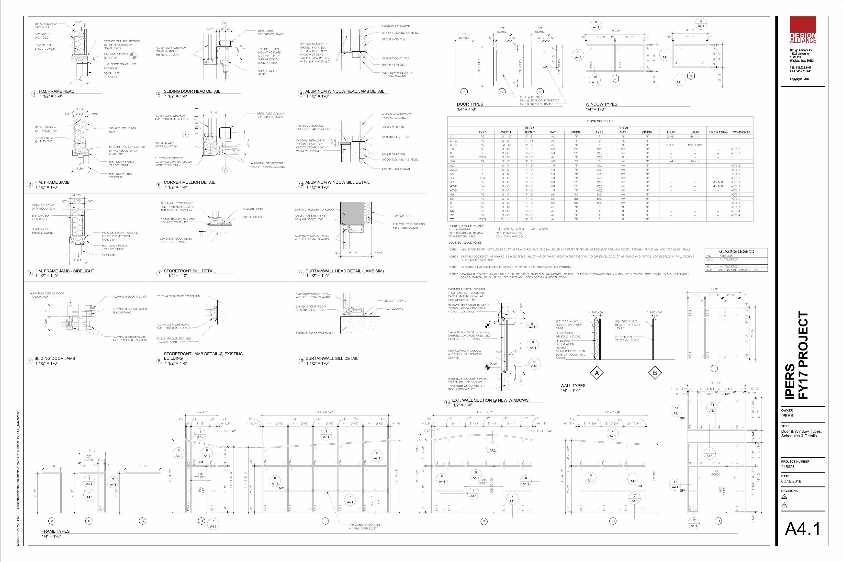
Door & Window Types,Schedules & Details
IPERS
FY17
PRO
JECT
1 1/2" = 1'-0"3 H.M. FRAME JAMB - SIDELIGHT
1 1/2" = 1'-0"9 ALUMINUM WINDOW HEAD/JAMB DETAIL
1 1/2" = 1'-0"10 ALUMINUM WINDOW SILL DETAIL
1/2" = 1'-0"13 EXT. WALL SECTION @ NEW WINDOWS
DOOR SCHEDULE
DOOR FRAMEHEAD JAMB FIRE RATING COMMENTSTYPE WIDTH HEIGHT MAT FINISH TYPE MAT FINISH
101-1 FG 12' - 10" 8' - 5" AL FF F AL FF 5/A4.1 4/A4.1 -- --101-2 FG 3' - 0" 7' - 11" AL FF D AL FF -- -- -- --101-3 FG 12' - 0" 8' - 5" AL FF H AL FF 4/A7.1 4/A4.1 SIM -- --116 FG 3' - 0" 7' - 0" WD SS B(E) HM PP -- -- -- NOTE 1121 FG 3' - 0" 7' - 0" WD SS B(E) HM PP -- -- -- NOTE 1122 FG(E) 3' - 0" 7' - 0" AL FF B(E) AL FF -- -- -- --124A FG 3' - 0" 7' - 0" WD SS B HM PP 1/A4.1 2/A4.1 -- --132-1 N 6' - 0" 7' - 0" HM PP C(E) HM PP -- -- -- NOTE 2132-2 N 6' - 0" 7' - 0" HM PP C(E) HM PP -- -- -- NOTE 1135 F 3' - 0" 7' - 0" HM PP A(E) HM PP -- -- -- NOTE 1143 F(E) 3' - 0" 7' - 0" HM PP A(E) HM PP -- -- -- NOTE 3147-1 FG 3' - 0" 7' - 0" WD SS B(E) HM PP -- -- 45 MIN NOTE 1147-2 FG 3' - 0" 7' - 0" WD SS B(E) HM PP -- -- 45 MIN NOTE 1147-3 F 3' - 0" 7' - 0" HM PP A(E) HM PP -- -- -- NOTE 1149 FG 3' - 0" 7' - 0" WD SS B(E) HM PP -- -- -- NOTE 1150 FG 3' - 0" 7' - 0" WD SS B(E) HM PP -- -- -- NOTE 1151 FG 3' - 0" 7' - 0" WD SS B(E) HM PP -- -- -- NOTE 1157 FG 3' - 0" 7' - 0" AL FF A AL FF -- -- -- NOTE 4166 FG 3' - 0" 7' - 0" AL FF A AL FF -- -- -- NOTE 4172 FG 3' - 0" 7' - 0" AL FF A AL FF -- -- -- NOTE 4177 FG(E) 5' - 11" 7' - 0" AL FF C AL FF -- -- -- --
DOOR SCHEDULE NOTES:
NOTE 1: NEW DOOR TO BE INSTALLED IN EXISTING FRAME: REMOVE ORIGINAL DOOR AND PREPARE FRAME AS REQUIRED FOR NEW DOOR. REFINISH FRAME AS INDICATED IN SCHEDULE.
NOTE 2: EXISTING DOORS SWING INWARD, NEW DOORS SHALL SWING OUTWARD. CONTRACTOR'S OPTION TO EITHER REUSE EXISTING FRAME AND ROTATE 180 DEGREES IN WALL OPENING,OR PROVIDE NEW FRAME.
NOTE 3: EXISTING DOOR AND FRAME TO REMAIN. PREPARE DOOR AND FRAME FOR PAINTING.
NOTE 4: NEW DOOR, FRAME AND/OR SIDELIGHT TO BE INSTALLED IN EXISTING OPENING AS PART OF EXTERIOR WINDOW AND GLAZING REPLACEMENT. NEW LAYOUT TO MATCH EXISTINGCONFIGURATION, FIELD VERIFY. SEE SHEET A5.1 FOR ADDITIONAL INFORMATION.
1 1/2" = 1'-0"5 SLIDING DOOR HEAD DETAIL
1 1/2" = 1'-0"6 CORNER MULLION DETAIL
1 1/2" = 1'-0"7 STOREFRONT SILL DETAIL
1 1/2" = 1'-0"8STOREFRONT JAMB DETAIL @ EXISTINGBUILDING
1 1/2" = 1'-0"1 H.M. FRAME HEAD
1 1/2" = 1'-0"2 H.M. FRAME JAMB
1 1/2" = 1'-0"4 SLIDING DOOR JAMB
1 1/2" = 1'-0"11 CURTAINWALL HEAD DETAIL (JAMB SIM)
1 1/2" = 1'-0"12 CURTAINWALL SILL DETAIL
FRAME TYPES1/4" = 1'-0"
DOOR TYPES1/4" = 1'-0"
WINDOW TYPES1/4" = 1'-0"
WALL TYPES1/4" = 1'-0"
DOOR SCHEDULE LEGEND:AL = ALUMINUM HM = HOLLOW METAL WD = WOOD(E) = EXISTING TO REMAIN PP = PRIME AND PAINTFF = FACTORY FINISH SS = STAIN AND SEAL
30' - 0" FIELD VERIFY
2' -
6"
F.V.
4' -
8"
30' - 0" FIELD VERIFY
2' -
6"
F.V.
4' -
8"
30' - 0" FIELD VERIFY
2' -
6"
F.V.
4' -
8"
157
25' - 1 3/8" FIELD VERIFY
F.V.
4' -
8"
1.11.1 1.1
2A7.2
1.5 1.4
1.1
1.5 1.4 1.5 1.4
2A7.2
2A7.2
EG-1
EG-1
EG-1
EG-1
EG-1
EG-1
EG-1
EG-1
EG-1
EG-1
EG-1
EG-1
EG-1
EG-1
EG-1
EG-1
EG-1
EG-1
EG-1
EG-1
EG-1
EG-1
EG-1
EG-1
EG-1
122 132-2 135 143 147-3
F.V.
6' - 0"
F.V.
4' -
6"
F.V.
6' - 0"
F.V.
4' -
0"
F.V.
6' - 0"
F.V.
4' -
6"
1.11.1 1.1
1.3 1.3 1.3 1.3
13A4.1
1' - 8" 10' - 0" 1' - 8" 10' - 0" 1' - 8"
4' -
8"
10' - 0" 25' - 0" 10' - 0"
1.1
10' - 0"
4' -
8"
10' - 0" 4' - 11 13/16"
4' -
8"
4' -
8"
1.21.2 1.1 1.1
A A
EG-1
EG-1
EG-1
EG-1
EG-1
EG-1
EG-1
EG-1
EG-1
EG-1
EG-1
EG-1
EG-1
EG-1
18' - 8" FIELD VERIFY
F.V.
4' -
8"
27' - 11" FIELD VERIFY
F.V.
4' -
8"
1.1
30' - 0"1.6
1.1
11
A4.1
11
A4.1SIM.
EG-1
EG-1
EG-1
EG-1
EG-1
EG-1
EG-1
EG-1
EG-1
EG-1
EG-1
EG-1
EG-1
EG-1
EG-1
EG-1
EG-1
EG-1
EG-1
EG-1
EG-1
EG-1
EG-1
EG-1
EG-1
EG-1
EG-1
EG-1
EG-1
EG-1
EG-1
EG-1
EG-1
EG-1
EG-1
EG-1
EG-1
EG-1
EG-1
EG-1
EG-1
EG-1
12
A4.1
EG-1
172166
29' - 8" FIELD VERIFY
F.V.
4' -
6"
25' - 0 7/16" FIELD VERIFY
F.V.
4' -
8"
33' - 9 3/4" FIELD VERIFY
29' - 1 13/16" FIELD VERIFY
F.V.
4' -
6"
F.V.
4' -
8"
10' - 0" F.V. 10' - 0" F.V.
10' - 0" F.V. 10' - 0" F.V.
F.V.
4' -
6"
F.V.
4' -
6"
F.V.
4' -
6"
F.V.
4' -
6"
1.1 1.1
1.1
1.1
1.1
1.11.1 1.1
19' -
8"
30' - 0"1.6
EG-1
EG-1
EG-1
EG-1
EG-1
EG-1
EG-1
EG-1
EG-1
EG-1
EG-1
EG-1
EG-1
EG-1
EG-1
EG-1
EG-1
EG-1
EG-1
EG-1
EG-1
EG-1
EG-1
EG-1
EG-1
EG-1
EG-1
EG-1
EG-1
EG-1
EG-1
EG-1
EG-1
EG-1
EG-1
EG-1
EG-1
EG-1
EG-1
EG-1
EG-1
EG-1
EG-1
EG-1
EG-1
EG-1
EG-1
EG-1
EG-1
EG-1
EG-1
EG-1
EG-1
EG-1
EG-1
EG-1
EG-1
EG-1
EG-1
EG-1
EG-1
EG-1
11
A4.1
11
A4.1 SIM
12
A4.1
EG-1
EG-1
EG-1
EG-1
EG-1
EG-1
Design Alliance Inc.14225 UniversitySuite 110Waukee, Iowa 50263
TEL 515.225.3469FAX 515.225.9649
1
2
Copyright: 2016
OWNER
TITLE
PROJECT NUMBER
DATE
REVISIONS
C:\U
sers
\twol
bers
\Doc
umen
ts\2
1602
6-FY
17Pr
ojec
t-RA1
6-C
D_t
wol
bers
.rvt
6/15
/201
6 2:
27:2
9 PM
IPER
S
A5.1
06.15.2016
216026
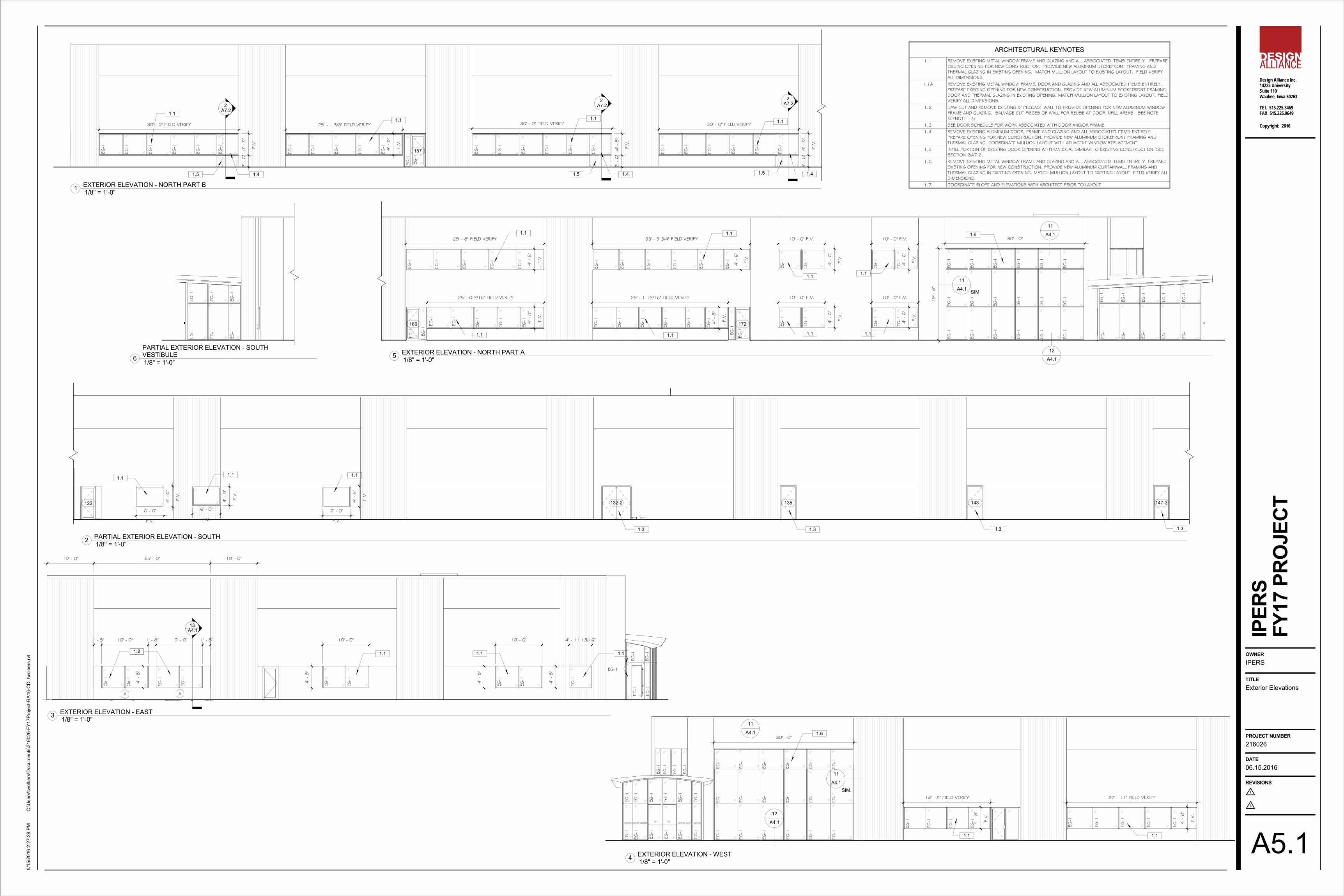
Exterior Elevations
IPERS
FY17
PRO
JECT
1/8" = 1'-0"1 EXTERIOR ELEVATION - NORTH PART B
1/8" = 1'-0"2 PARTIAL EXTERIOR ELEVATION - SOUTH
1/8" = 1'-0"3 EXTERIOR ELEVATION - EAST
1/8" = 1'-0"4 EXTERIOR ELEVATION - WEST
1/8" = 1'-0"5 EXTERIOR ELEVATION - NORTH PART A
ARCHITECTURAL KEYNOTES1.1 REMOVE EXISTING METAL WINDOW FRAME AND GLAZING AND ALL ASSOCIATED ITEMS ENTIRELY. PREPARE
EXISING OPENING FOR NEW CONSTRUCTION. PROVIDE NEW ALUMINUM STOREFRONT FRAMING ANDTHERMAL GLAZING IN EXISTING OPENING. MATCH MULLION LAYOUT TO EXISTING LAYOUT. FIELD VERIFYALL DIMENSIONS.
1.1A REMOVE EXISTING METAL WINDOW FRAME, DOOR AND GLAZING AND ALL ASSOCIATED ITEMS ENTIRELY.PREPARE EXISTING OPENING FOR NEW CONSTRUCTION. PROVIDE NEW ALUMINUM STOREFRONT FRAMING,DOOR AND THERMAL GLAZING IN EXISTING OPENING. MATCH MULLION LAYOUT TO EXISTING LAYOUT. FIELDVERIFY ALL DIMENSIONS.
1.2 SAW CUT AND REMOVE EXISTING 8" PRECAST WALL TO PROVIDE OPENING FOR NEW ALUMINUM WINDOWFRAME AND GLAZING. SALVAGE CUT PIECES OF WALL FOR REUSE AT DOOR INFILL AREAS. SEE NOTEKEYNOTE 1.5.
1.3 SEE DOOR SCHEDULE FOR WORK ASSOCIATED WITH DOOR AND/OR FRAME.1.4 REMOVE EXISTING ALUMINUM DOOR, FRAME AND GLAZING AND ALL ASSOCIATED ITEMS ENTIRELY.
PREPARE OPENING FOR NEW CONSTRUCTION. PROVIDE NEW ALUMINUM STOREFRONT FRAMING ANDTHERMAL GLAZING. COORDINATE MULLION LAYOUT WITH ADJACENT WINDOW REPLACEMENT.
1.5 INFILL PORTION OF EXISTING DOOR OPENING WITH MATERIAL SIMILAR TO EXISTING CONSTRUCTION. SEESECTION 2/A7.2.
1.6 REMOVE EXISTING METAL WINDOW FRAME AND GLAZING AND ALL ASSOCIATED ITEMS ENTIRELY. PREPAREEXISTING OPENING FOR NEW CONSTRUCTION. PROVIDE NEW ALUMINUM CURTAINWALL FRAMING ANDTHERMAL GLAZING IN EXISTING OPENING. MATCH MULLION LAYOUT TO EXISTING LAYOUT. FIELD VERIFY ALLDIMENSIONS.
1.7 COORDINATE SLOPE AND ELEVATIONS WITH ARCHITECT PRIOR TO LAYOUT
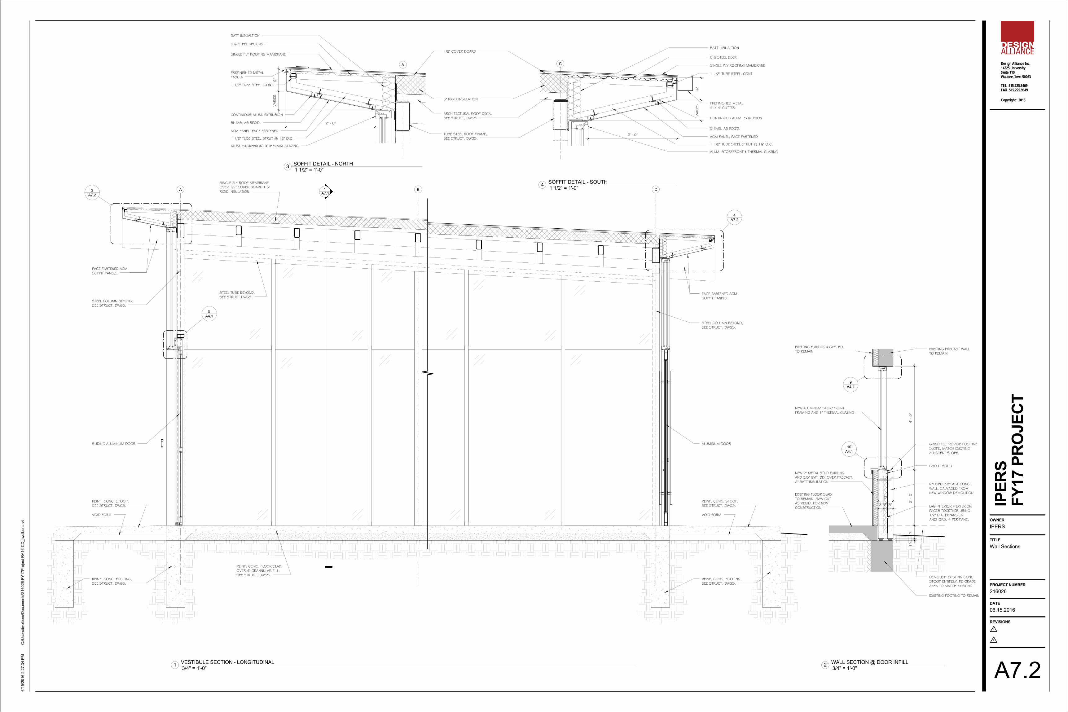
1/8" = 1'-0"6PARTIAL EXTERIOR ELEVATION - SOUTHVESTIBULE
CURVED STEEL PURLINS,SEE STRUCT. DWGS.
ARCHITECTURAL ROOF DECK,SEE STRUCT. DWGS.
1" RIGID INSULATION
2' - 0" 7 1/2" VARIES VARIES 7 1/2"
A7.13
STEEL TUBE,SEE STRUCT. DWGS.
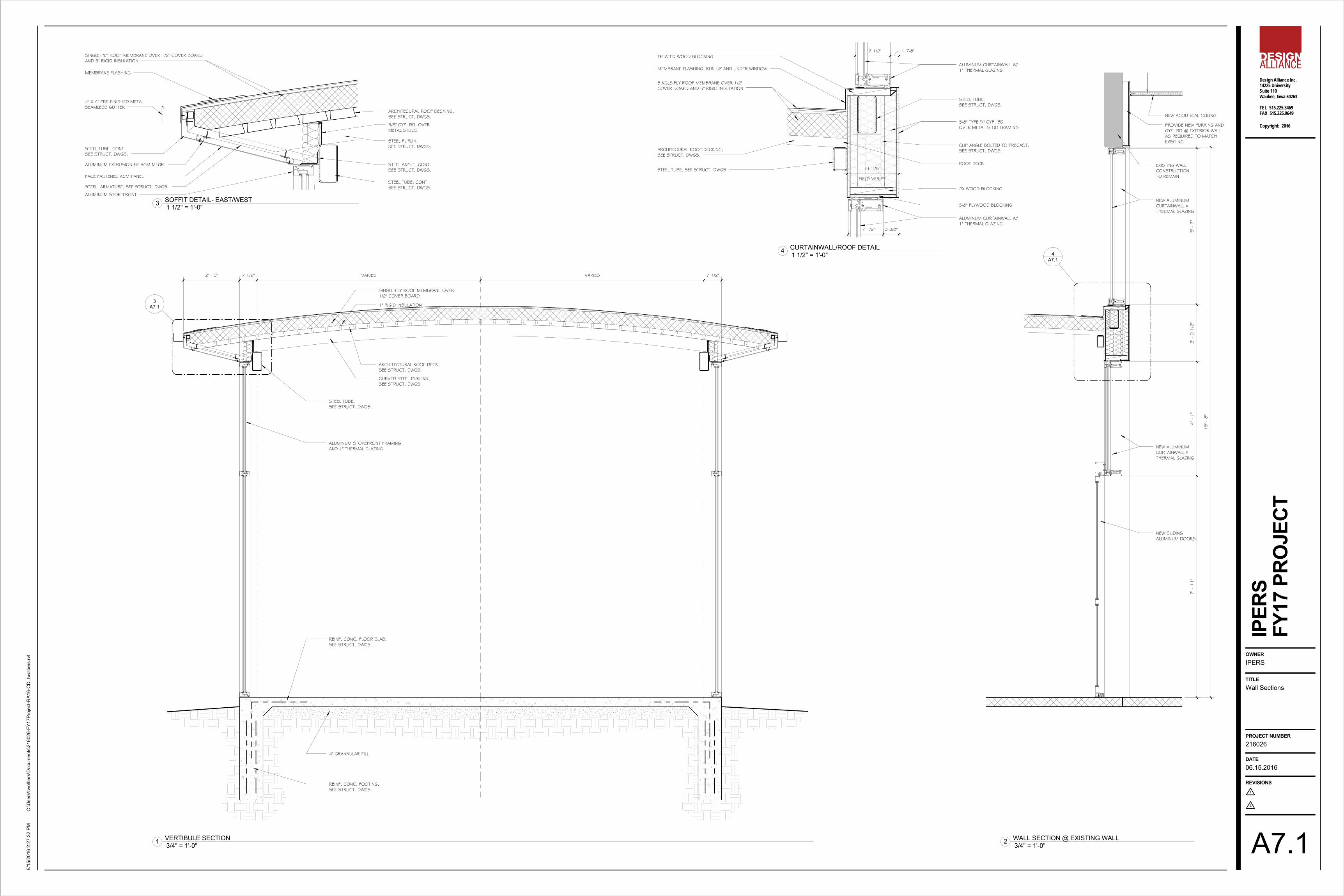
ALUMINUM STOREFRONT FRAMINGAND 1" THERMAL GLAZING
REINF. CONC. FLOOR SLAB,SEE STRUCT. DWGS.
REINF. CONC. FOOTING,SEE STRUCT. DWGS.
4" GRANNULAR FILL
SINGLE-PLY ROOF MEMBRANE OVER1/2" COVER BOARD
5' -
7"
2' -
0 1
/2"
4' -
1"
7' -
11"
19' -
8"
A7.14
NEW ACOUTICAL CEILING
PROVIDE NEW FURRING ANDGYP. BD @ EXTERIOR WALLAS REQUIRED TO MATCHEXISTING
NEW ALUMINUMCURTAINWALL &THERMAL GLAZING
NEW ALUMINUMCURTAINWALL &THERMAL GLAZING
NEW SLIDINGALUMINUM DOORS
EXISTING WALLCONSTRUCTIONTO REMAINFACE FASTENED ACM PANEL
ALUMINUM EXTRUSION BY ACM MFGR.
STEEL ARMATURE, SEE STRUCT. DWGS.
ALUMINUM STOREFRONT
4" X 4" PRE-FINISHED METALSEAMLESS GUTTER
MEMBRANE FLASHING
STEEL TUBE, CONT.SEE STRUCT. DWGS.
SINGLE-PLY ROOF MEMBRANE OVER 1/2" COVER BOARDAND 5" RIGID INSULATION
STEEL TUBE, CONT.SEE STRUCT. DWGS.
STEEL ANGLE, CONT.SEE STRUCT. DWGS.
5/8" GYP. BD. OVERMETAL STUDS
ARCHITECURAL ROOF DECKING,SEE STRUCT, DWGS.
STEEL PURLIN,SEE STRUCT. DWGS.
STEEL TUBE,SEE STRUCT. DWGS.
CLIP ANGLE BOLTED TO PRECAST,SEE STRUCT. DWGS.
ROOF DECKSTEEL TUBE, SEE STRUCT. DWGS
SINGLE-PLY ROOF MEMBRANE OVER 1/2"COVER BOARD AND 5" RIGID INSULATION
ARCHITECURAL ROOF DECKING,SEE STRUCT, DWGS.
MEMBRANE FLASHING, RUN UP AND UNDER WINDOW
FIELD VERIFY
11 1/8"
TREATED WOOD BLOCKING7 1/2" 1 7/8"
ALUMINUM CURTAINWALL W/1" THERMAL GLAZING
5/8" TYPE "X" GYP. BD.OVER METAL STUD FRAMING
ALUMINUM CURTAINWALL W/1" THERMAL GLAZING
7 1/2" 3 3/8"
2X WOOD BLOCKING
5/8" PLYWOOD BLOCKING
Design Alliance Inc.14225 UniversitySuite 110Waukee, Iowa 50263
TEL 515.225.3469FAX 515.225.9649
1
2
Copyright: 2016
OWNER
TITLE
PROJECT NUMBER
DATE
REVISIONS
C:\U
sers
\twol
bers
\Doc
umen
ts\2
1602
6-FY
17Pr
ojec
t-RA1
6-C
D_t
wol
bers
.rvt
6/15
/201
6 2:
27:3
2 PM
IPER
S
A7.1
06.15.2016
216026
Wall Sections
IPERS
FY17
PRO
JECT
3/4" = 1'-0"1 VERTIBULE SECTION 3/4" = 1'-0"2 WALL SECTION @ EXISTING WALL
1 1/2" = 1'-0"3 SOFFIT DETAIL- EAST/WEST
1 1/2" = 1'-0"4 CURTAINWALL/ROOF DETAIL
CA 1A7.1A7.2
3
A7.24
A4.15
B
SLIDING ALUMINUM DOOR
VOID FORM
REINF. CONC. STOOP,SEE STRUCT. DWGS.
REINF. CONC. FOOTING,SEE STRUCT. DWGS.
REINF. CONC. FLOOR SLABOVER 4" GRANNULAR FILL,SEE STRUCT. DWGS.
STEEL TUBE BEYOND,SEE STRUCT DWGS.
SINGLE PLY ROOF MEMBRANEOVER 1/2" COVER BOARD & 5"RIGID INSULATION
STEEL COLUMN BEYOND,SEE STRUCT. DWGS.
FACE FASTENED ACMSOFFIT PANELS
ALUMINUM DOOR
VOID FORM
REINF. CONC. STOOP,SEE STRUCT. DWGS.
REINF. CONC. FOOTING,SEE STRUCT. DWGS.
STEEL COLUMN BEYOND,SEE STRUCT. DWGS.
FACE FASTENED ACMSOFFIT PANELS
3" 2" 3"
8"
1"
7"
2' -
6"
4' -
8"
REUSED PRECAST CONC.WALL, SALVAGED FROMNEW WINDOW DEMOLITION
DEMOLISH EXISTING CONC.STOOP ENTIRELY. RE-GRADEAREA TO MATCH EXISTING
EXISTING FLOOR SLABTO REMAIN, SAW CUTAS REQ'D. FOR NEWCONSTRUCTION
NEW 2" METAL STUD FURRINGAND 5/8" GYP. BD. OVER PRECAST,2" BATT INSULATION
A4.110
A4.19
NEW ALUMINUM STOREFRONTFRAMING AND 1" THERMAL GLAZING
EXISTING PRECAST WALLTO REMAIN
EXISTING FURRING & GYP. BD.TO REMAIN
GRIND TO PROVIDE POSITIVESLOPE, MATCH EXISTINGADJACENT SLOPE.
LAG INTERIOR & EXTERIORFACES TOGETHER USING1/2" DIA. EXPANSIONANCHORS, 4 PER PANEL
GROUT SOLID
EXISTING FOOTING TO REMAIN
A
ACM PANEL, FACE FASTENED
CONTINIOUS ALUM. EXTRUSION
SHIMS, AS REQ'D.
1 1/2" TUBE STEEL STRUT @ 16" O.C.TUBE STEEL ROOF FRAME,SEE STRUCT. DWGS.
ALUM. STOREFRONT & THERMAL GLAZING
0.6 STEEL DECKING
PREFINISHED METALFASCIA
1 1/2" TUBE STEEL, CONT.
SINGLE PLY ROOFING MAMBRANE
6"
VARIE
S
2' - 0"
1/2" COVER BOARD
5" RIGID INSULATION
ARCHITECTURAL ROOF DECK,SEE STRUCT. DWGS
BATT INSUALTION
C
ACM PANEL, FACE FASTENED
CONTINIOUS ALUM. EXTRUSION
SHIMS, AS REQ'D.
1 1/2" TUBE STEEL STRUT @ 16" O.C.
ALUM. STOREFRONT & THERMAL GLAZING
0.6 STEEL DECK
PREFINISHED METAL4" X 4" GUTTER
1 1/2" TUBE STEEL, CONT.
SINGLE PLY ROOFING MAMBRANE
2' - 0"
6"
VARIE
S
BATT INSUALTION
Design Alliance Inc.14225 UniversitySuite 110Waukee, Iowa 50263
TEL 515.225.3469FAX 515.225.9649
1
2
Copyright: 2016
OWNER
TITLE
PROJECT NUMBER
DATE
REVISIONS
C:\U
sers
\twol
bers
\Doc
umen
ts\2
1602
6-FY
17Pr
ojec
t-RA1
6-C
D_t
wol
bers
.rvt
6/15
/201
6 2:
27:3
4 PM
IPER
S
A7.2
06.15.2016
216026
Wall Sections
IPERS
FY17
PRO
JECT
3/4" = 1'-0"1 VESTIBULE SECTION - LONGITUDINAL 3/4" = 1'-0"2 WALL SECTION @ DOOR INFILL
1 1/2" = 1'-0"3 SOFFIT DETAIL - NORTH
1 1/2" = 1'-0"4 SOFFIT DETAIL - SOUTH
DESIGN CRITERIA
D1) Codes:
International Building Code, 2012American Concrete Institute 318-10American Institute of Steel ConstructionSteel Construction Manual Fourteenth Ed.
D2) Lateral loads:
Wind: Basic wind speed: 115 mph Wind exposure: B Interior pressure coefficient: GCpi=0.18Wall component wind pressure: 20.0 psf
D3) Live loads:
Ground snow load: 30 psf Flat-roof snow load (minimum): Pf=24 psf Snow exposure factor: Ce=1.00 Thermal factor: Ct=1.00 Snow drift load: ASCE-7-10Roof load (minimum) 20 psf
D4) Net allowable soil bearing pressures:
Column footings: 1500 psfWall footings: 1500 psf
D5) Concrete strengths - Minimum 28 day f 'c(145 pcf density unless noted otherwise)
Typical-unless noted otherwise: 4000 psiFootings: 3000 psiSlabs on grade Interior: 4000 psi
D6) Reinforcing steel shall be high strength new billet steel conforming to thefollowing:
Deformed bars: ASTM A615, Gr. 60 (unless otherwise noted)Welded wire reinforcing: ASTM A185D7) Structural steel:
W- shapes: A992Other rolled shapes and connection material: ASTM A36Anchor bolts: ASTM F1554High Strength bolts: A325/A490 (3/4" diameter U.N.O.)Structural tubes: ASTM A500, Gr. B
SPECIAL INSPECTION REQUIREMENTS
SR1) The following types of work require special inspection based on section1704 of the 2012 International Building Code. See Specification section 01410for specific requirements. The owner will employ special inspectors who shallprovide special inspections during:
a) Cast-in-place Concrete.b) Structural Steel.
GENERAL NOTES
G1) Establish and verify all openings and inserts for mechanical, electrical, andplumbing with appropriate trade contractors. Opening sizes and locationsshown for ducts, pipes, inserts, etc., when shown are for general informationonly and shall be verified prior to forming.
G2) Field verify all existing dimensions, member sizes, and elevations shownon the drawings. All discrepancies shall be immediately brought to theattention of the architect.
G3) Before submitting a proposal for this work, each bidder shall visit thepremises and acquaint themselves fully with the existing conditions, temporaryconstruction required, quantities and types of equipment, etc. The bid shallinclude all sums required to do the work within the existing conditions.Disruption of normal activities in the work area must be kept to a minimum.
G4) Shop drawings prepared by suppliers, subcontractors, etc. shall bereviewed and coordinated prior to submitting to the architect. Each shopdrawing submitted shall be stamped, initialed, and dated as being reviewed bythe construction manager/general contractor.
G5) Shop drawings prepared by the subcontractors, suppliers, etc. shall bereviewed by the architect for conformance with design concept only. Reviewby the architect shall not begin without the prior coordination and review by theconstruction manager/general contractor. Work shall not begin without thereview by the architect.
G6) Details and notes on the structural drawings are intended to be typical forsimilar situations elsewhere. Verify all dimensions with the architecturaldrawings. Do not scale drawings; use dimensions provided only.
G7) Options are for the contractor's convenience. The contractor shall beresponsible for all changes necessary if they choose an option and shallcoordinate all details. The cost of additional design work necessitated byselection of an option shall be borne by the contractor.
G8) The cost of additional design work due to errors or omissions inconstruction shall be borne by the contractor.
G9) Any engineering design provided by others and submitted for review orrecord shall bear the stamp and signature of a professional structural engineerlicensed in the state of Iowa.
G10) All elevations given thus (+10'-0") are to top of footing, joist bearing, topof steel, top of slab, etc. with reference to the finished first floor slab = (0'-0").
CONSTRUCTION PROCEDURES
AND SAFETY REQUIREMENTS
P1) Comply with all applicable city, county, state, and federal laws, includingthe Occupational Safety and Health Act (OSHA) and regulations adoptedpursuant thereto.
P2) The contract structural drawings and specifications represent the finishedstructure. Unless otherwise indicated, they do not indicate the means ormethods of construction.
P3) Provide all measures necessary to protect the workers and other personsduring construction. Provide all necessary measures to avoid excessivestresses and to hold the structural elements in place during construction. Suchmeasures shall include, but not be limited to, bracing, shoring for constructionequipment, shoring for earth banks forms, scaffolding, planking, safety nets,support and bracing for cranes and hoists, guying, etc.
P4) Engage properly qualified persons to determine where and how temporaryprecautionary measures shall be used. Observation visits to the site bystructural engineer's field representatives shall not include the items notedabove.
P5) Supervise and direct the work so as to maintain sole responsibility for allconstruction means, methods, techniques, sequences, and procedures. Retainthe services of a professional structural engineer licensed in the state of Iowa todesign and supervise any scaffolding for workmen, and all shoring of forms andelements of the construction.
P6) Any engineering design provided by others and submitted for reviewand/or record shall bear the stamp and signature of a professional structuralengineer licensed in the state of Iowa.
FOOTINGS AND FOUNDATIONS
F1) All footings shall be placed onto firm undisturbed soil or controlledcompacted fill as directed by the project soils consultant reportrecommendations. Footing elevations shown designate a minimum depth offootings where a safe soil bearing pressure is expected (see Design Criteria).Footings shall be lowered and piers and/or walls extended as required to reachthe design bearing pressure.
F2) General machine excavation for footings done more than 12 hours beforethe footing is placed shall stop not less than 4" above the elevation of bottomsof footings. Final excavation to the required undisturbed soil elevation shall bedone not more than 12 hours before the footing is placed. The excavation shallbe crumbed clean.
F3) All foundation excavations shall be inspected and certified by a qualifiedindependent soils testing firm.
F4) No footing shall be placed onto or against sub-grades containing freewater, frost, or ice.
F5) Unless noted otherwise, all footings shall be centered under walls, piers, orcolumns.
F6) Where required, all necessary changes in elevation of wall footings shall bemade in steps of 1 vertical to 2 horizontal. Location of steps shall becoordinated with the wall forming system and at least 2'-0" apart.
F7) Longitudinal reinforcing in wall footings shall be continuous at step downs.Slope or step bottom bars in wall to follow steps in footing unless otherwiseshown. See typical step-down footing detail.
F8) Lap wall footing reinforcing 24 bar diameters or a minimum of 1'-6" atsplices, unless otherwise noted.
F9) Provide corner bars in footings the same size and number as thecontinuous reinforcing, lapped 2'-0" with main steel.
F10) Reinforcing in wall footings between columns shall extend into columnfootings a minimum of 2'-0".
F11) Reinforcing in footings shall be accurately placed, spaced, supported,and secured before placing concrete (do not "float" reinforcing into footings).
F12) Pipes extending under footings shall be placed before footing is placedand the void produced in laying the pipe shall be filled with concrete.
F13) Cross reference architectural and structural drawings to assure properdimensions and placement of all anchor bolts, inserts, notches, and edges ingrade beams, foundation walls, and piers.
F14) All unacceptable fill and top soil shall be removed from below allproposed slabs-on-grade and the exposed natural soil shall be proof rolled andthe compaction verified by a qualified independent soils testing firm prior toplacing fill. Areas exhibiting weakness shall be removed and replaced byacceptable compacted fill.
F15) A minimum 4" of clean compacted granular fill shall be placed under allslabs-on-grade. All fill required to attain final sub-grade for slabs and walls shallbe an acceptable material placed and compacted as directed by the projectsoils consultant recommendations.
F16) A vapor barrier with minimum 15 mil thickness shall be placed under allinterior slab-on-grade or below granular fill; see architectural drawings. Lap andseal all edges.
CONCRETE AND REINFORCING
C1) All concrete work shall conform to the latest edition of the AmericanConcrete Institute Publications: ACI 301, ACI 304, ACI 311, ACI 315, ACI 318,and ACI 347 unless otherwise noted on the drawings.
C2) Concrete shall consist of the following:
ASTM C150Type I Portland cementASTM C33Normal weight aggregates (Limestone aggregate at exposed locations)ASTM C330Light weight aggregatesPotable waterChlorides content shall be limited by ACI requirements for type of exposure.Concrete which will be subjected to repeated cycles of freeze-thaw during thelife of the structure shall have a water-cement ratio not exceeding 0.53 andshall contain entrained air. See ACI 301 for additional requirements.
C3) Unless otherwise noted, principal reinforcement shall have the followingprotection:
Surfaces cast against & permanently exposed to earth: 3 inchesFormed surfaces exposed to earth or water: 2 inchesSlabs: 1 inch (top) 3/4 inch (bot.)Beams, columns: 2 inchesWalls (interior surface only): 1 inchTies/Stirrups: 1 1/2 inches
C4) All slabs-on-grade, pads, fills, and toppings shall have a minimum of 6 x 6- W1.4 x W1.4 WWR, unless noted otherwise, placed 1" from top of slab. LapWWR minimum 2 panels at edges and ends and provide additional reinforcingwhere shown on the drawings.
C5) All slabs-on-grade shall be placed on compacted granular fill. Pitch slabsto drains and provide depressions, where shown on the structural orarchitectural drawings, without reducing the thickness of slab indicated. Forslabs on grade depressions greater than 1", see details for additionalreinforcing.
C6) Provide slab-on-grade construction joints around each column, againstgrade beams, interior walls, and between columns and walls. Provide slabjoints to form areas not to exceed 15' in length in each direction. See typicaldetails. Submit detailed drawings showing locations of all construction joints.
C7) Provide adequate bolsters, hi-chairs, support bars, etc., to maintainspecified clearances for the entire length of all reinforcing bars. Provideaccessories which are plastic tipped or galvanized with turned up ends forreinforcement at all faces of exposed concrete, interior or exterior.
C8) Unless otherwise noted, no concrete shall be placed without a minimumreinforcing of 0.002 times the concrete cross sectional area in each direction.
C9) Continuous reinforcing shall be lapped as follows unless otherwise noted:
Top bars: at midspan, Class BBottom bars: directly over support, Class BAll laps shown on the drawings and not dimensioned shall be 24 bar diameters.Additional laps required for construction shall be Class B.
C10) All field bending of reinforcing shall be done cold. Heating of bars will notbe permitted.
C11) No aluminum of any type shall be allowed in the concrete work unlesscoated to prevent aluminum-concrete reaction.
C12) Maximum O.D. of embedded conduit shall be no larger than 1/3 of theslab thickness. No conduit shall be placed above the welded wire fabric inslabs- on-grade.
C13) Mechanically vibrate concrete except that slabs-on-grade need only bevibrated around under floor ducts and other embedded items.
C14) All construction joints between adjacent concrete pours shall be keyed.Joints must be kept free of dirt, debris, form oils, etc. to assure proper bondwith adjacent pour or masonry construction.
C15) Do not place pipes, ducts, reglets or chases in structural concrete orcomposite floor systems without approval of the structural engineer through thearchitect.
C16) Floor tolerances:Surface tolerance: Class B. (See ACI 301)Thickness: plus 1", minus 1/2" slab on grade plus 1", minus 1/4" structural andcomposite slabs. Replace any slab with a thickness deviation as directed by thearchitect.
C17) Maximum free drop of any concrete = 6'-0".
C18) All bar detailing and accessories to be furnished shall conform to typicaldetails and standards in the latest ACI Standard 315 Detailing Manual, exceptas otherwise shown, noted, or specified.
STRUCTURAL STEEL
S1) Structural steel details, fabrication, and erection shall conform to the latestedition of the AISC "Manual of Steel Construction - ASD" unless otherwiseshown or specified.
S2) All welding shall be done by AWS certified welders with experience andcertification in the types of welding indicated. Certificates shall not have lapseddue to disuse for 6 months.
S3) All welds to be E70XX electrodes unless noted otherwise.
S4) Field connections shall be welded or bolted. Shop connections shall bewelded unless otherwise indicated or approved. Welds indicated with a shopweld symbol may be made in the field with the approval of the structuralengineer.
S5) Unless noted otherwise, all welds shall be continuous 3/16" throat. All fulland/or partial penetration welds shall be fully detailed on the shop drawing.
S6) Fabricator shall select AISC simple shear connections for steel beamscapable of carrying the reaction force when indicated or 75% of the totaluniform load for the given size, span, and grade of beam, as tabulated in theAISC tables for allowable loads.
S7) Simple shear connections shall be standard double angle or single shearplates, unless noted otherwise. Select connections from the AISC, SimpleShear Connections Design Aid, latest edition whenever possible. All boltedconnections shall have minimum 2 bolts, unless noted otherwise.
S8) Shop paint structural steel with a standard primer.
S9) Grout under beam bearing plates and column base plates.
S10) Embedment of anchors in masonry, grout, or concrete shall be asfollows: Headed anchor bolts: 9" with the head at the embedded end.S11) Cuts, holes, openings, etc., required in structural steel members for thework of other trades shall be shown on the shop drawings. Burning of holesand cuts in the field shall not be allowed, except by written authorization fromthe structural engineer.
S12) Furnish and install miscellaneous steel (curbs, hangers, expansion jointangles, struts, etc.) as called for or as necessary per architectural andmechanical/electrical drawings.
S13) See specifications for minimum testing requirements for materials,connections, welding, and erection.
STEEL DECK
SD1) Material, detailing, design, manufacture, and erection of metal decksshall be in accordance with the Steel Deck Institute (SDI) Specification.
SD2) Metal deck shall be capable of providing a diaphragm shear capacity asnoted below in accordance with the current ICBO Research Recommendationsfor simple span conditions:
Roof Deck: 200 plf
Minimum factor of safety shall be 2.0.
SD3) In no case shall welding to steel members be less than 5/8" diameterpuddle welds at all supports and edges. Provide 16 gage welding washerswhen recommended by the manufacturer for the gage of metal deck specifiedbelow. Side laps shall be fastened with #10 tek screws, minimum one at eachmidspan. Opening edges shall receive the same welding as required at deckends. All welding by certified welders experienced in light gage metal deckwork.
SD4) The deck manufacturer shall furnish all closure plates, pour stops, ridgeand valley plates, sump pans and drain plates, welding washers, and otheraccessories required to provide a finished surface for insulation and roofing.
SD5) Install deck with a minimum 2" end lap centered over supports.
SD6) All metal roof deck shall be painted.
SD7) Loads are permitted to be hung from metal roof decking. All hangingloads, locations, and details shall be submitted to the structural engineerthrough the architect.
SD8) Roof deck shall have the following minimum properties:
Gage 20 ga.Depth 2.0 inches (maximum)Type Epic Epicore ER2R
SD9) Submit shop drawings showing erection procedures, weldingprocedures, the lCBO report number, vertical load and diaphragm shearcapacity furnished, deck shoring requirements, U.L. fire rating number, andcomposite beam and girder stud profiles to the architect for review. Fabricationshall not begin without approved shop drawings.
Design Alliance Inc.14225 UniversitySuite 110Waukee, Iowa 50263
TEL 515.225.3469FAX 515.225.9649
1
2
Copyright: 2016
OWNER
TITLE
PROJECT NUMBER
DATE
REVISIONS
C:\_
Revit 2
01
6 L
oca
l F
iles\C
SE
-IP
ER
S V
estib
ule
Ad
ditio
n-R
20
16
-T6
06
00
.rvt
6/1
5/2
01
6 1
0:5
9:1
7 A
M
IPE
RS
S0.1
06/15/16
216026
STRUCTURALNOTES
IPERS
FY
17 P
RO
JE
CT
S

0'-7 1/2" 21'-4 1/2" 0'-7 1/2"
22'-7 1/2"
5'-0"
5'-8
3/4
"
5'-1
5/8
"0
'-7
1/4
"
2'-1 3/4"
2'-1
3/4
"
0'-7
3/4
"1
6'-5
1/4
"0
'-7
3/4
"
17
'-8
3/4
"
5'-0" 0'-7 1/2" 11'-4 1/4"
DRILL & EPOXYCONT REINF 6"INTO EXISTGFDN-TYP
1'-0"X3'-6" CONC TRENCHFTG W/ 2-#5 CONT TOP &BOT & #4 VERT @ 1'-6" OC
4" CONC SLAB ON GRADEW/ 6X6 W1.4XW1.4 WWRON 4" WELL COMPACTEDGRANULAR FILL-TOP OFSLAB EL-(0'-0"
8"X3'-6" CONCTRENCH FTG
5'-0"
• FOR TYP CONC SLAB JOINTS SEE B3/S1.1• FOR TYP CONC WALL CORNER & INTERSECTION
SEE C3/S1.1
A3
S1.1
A3
S1.1
Sim
D3
S1.1
D3
S1.1
-0'-8"
7SPACES @ 2'-8"OC 2'-8 1/2"
0'-7 1/2" 21'-4 1/2" 0'-7 1/2"
22'-7 1/2"
2'-1 3/4"
2'-1
3/4
"
0'-7
3/4
"1
6'-5
1/4
"0
'-7
3/4
"
17
'-8
3/4
"
0'-7 1/2" 11'-4 1/4"
ROLLED TO RADIUS
HSS5X3X3/8
HSS8X4X1/4
HSS8X4X1/4
HS
S8
X4
X3
/8 R
OLL
ED
TO
RA
DIU
S
HS
S4
X2
X1
/4 L
DH
(+
8'-7
1/2
")
HS
S8
X4X
3/8
RO
LLE
D T
O R
AD
IUS
20 GA MTL RF DECK
EPICORE ER2R
(SLOPES)
(SLOPES)
A2
S1.1
B2
S1.1
C2
S1.1
HSS8X
4X1/
4A1
S1.1
A1
S1.1
D2
S1.1
HSS4X
4X1/
4
COL-
TYP
TOS = (+12'-2 9/16")
TOS = (+11'-10 3/16")TOS = (+11'-5 13/16")
TOS = (+12'-2 9/16")
GRID
WINDOWS -SEE ARCHDWGS
EL-SEE PLAN
1-#4 CONT
BASE PL3/4"X7"X10" W/ 4-3/4"øX9" MINEMBED HEADERANCHOR
STL COL - SEEPLAN
#4 DOWELSTHUS: 2'-0"
2'-0"
CONC SLAB ONGRADE-SEE PLAN
COMPACTEDGRANULAR FILL
1 1/2" NON SHRINKGROUT
TRENCH FTG - SEEPLAN FOR SIZE &REINF
0'-7 1/2"
0'-7" TYP0'-1 1/2"
"T"/
3
"T"
SL
AB
TH
ICK
NE
SS
2 x
SL
AB
TH
ICK
NE
SS
WWR 2x4 KEY CONT
CONC SLAB- SEE PLAN
1'-0"
WWR
CONC SLAB- SEE PLAN
SAW-CUT JOINT
CONSTRUCTION JOINT
SAW-CUT JOINT
CONCRETE SLAB JOINTS TO BE EITHER CONSTRUCTION OR SAW-CUT JOINTS
MAXIMUM SPACING OF SLAB JOINTS NOT TO EXCEED 15'-0" IN ANY DIRECTION
LOCATE CONSTRUCTION JOINTS ON COLUMN CENTERLINE
LOCATE SAW-CUT JOINTS BETWEEN CONSTRUCTION JOINTS
LOCATE SLAB JOINTSAT PARTITIONS WHERE POSSIBLE
EL-SEE PLAN
EL-SEE PLAN
2x4 KEY IFCONSTRUCTIONJOINT IS DESIRED
PROVIDE CORNERREINF SAME SIZE& SPACING ASHORIZ REINF
WALL INTERSECTION WALL CORNER
2'-0
"
2'-0" 2'-0"
2'-0
"
5" CONC SLAB W/#4 @ 12" OC EAWAY
SLOPE DOWN
4" VOID FORM
#4 @ 12" OCTHUS:
2'-0"
2'-0
"
TRENCH FTG -SEE PLAN FORSIZE & REINF
FACE OF WALLBEYOND
1/2" EXP JOINTMATERIAL-SEEARCH DWGS FORLOCATION
CONC SLAB-SEE PLAN
1-#4 CONT
RIGID INSUL-SEE ARCHDWGS
3'-10 1/4"SEE PLAN
EL-SEE PLAN
EL-SEE PLAN
MIN
0'-6
"
MTL RF DECK-SEE PLAN
EL-SLOPES
STL BM-SEEPLAN
COPE BM END
STL BM-SEEPLAN
WINDOWS-SEEARCH DWGS
0'-4
"
EL-SEE ARCH
L4X3X1/4LLH
SEEARCH DWGS
0'-4
"
STL BM-SEEPLAN
BENT PL-8"X3"X1/4"X0'-3"LLH
STL BM-SEEPLAN
STL COL-SEEPLAN
EL-SLOPES
MTL RF DECK-SEE PLAN
MTL RF DECK-SEE PLANL5X3 1/2X1/4
LLV-MATCH BMRADIUS
EL-SEE ARCH
WINDOWS-SEEARCH DWGS
L4X3X1/4 LLH-MATCH BMRADIUS
STL BM-SEEPLAN
2@12
2@12
2@12
EL-SEE ARCH
STL BM-SEE PLAN
STOP DECKING IN LINE W/FACE OF PRECAST TOALLOW SPANDREL FRAMING
MTL ROOF DECK- SEE PLAN
3"
RADIUSED STL BM- SEE PLAN
L3X3X1/4 EA FACE OFRADIUSED BM- PLACE ANGLEFLAT TO FACE OF RADIUSEDBM &^ SKEWED ON BM ABOVE
3 L
OC
AT
ION
S
VA
RIE
S
0'-4 1/4"
EL-VARIES
3" MIN
STL BEAM- SEEPLAN- SLOT ENDOF TUBE
WT6X13 X 0'-10" W/4-1/2"øX4" EMBEDTHREADED ROD W/POWERS AC100GOLD ADHESIVE
1 1
/2"
1 1
/2"
EXISTING PRECASTCONC WALL
Design Alliance Inc.14225 UniversitySuite 110Waukee, Iowa 50263
TEL 515.225.3469FAX 515.225.9649
1
2
Copyright: 2016
OWNER
TITLE
PROJECT NUMBER
DATE
REVISIONS
C:\_
Revit 2
01
6 L
oca
l F
iles\C
SE
-IP
ER
S V
estib
ule
Ad
ditio
n-R
20
16
-T6
06
00
.rvt
6/1
5/2
01
6 1
1:0
0:2
3 A
M
IPE
RS
S1.1
06/15/16
216026
STRUCTURAL PLANS& DETAILS
IPERS
FY
17 P
RO
JE
CT
S
1/4" = 1'-0"A4
FOUNDATION PLAN
1/4" = 1'-0"C4
ROOF FRAMING PLAN
1" = 1'-0"A3
COLUMN @ FOOTING
3/4" = 1'-0"B3
TYP CONC SLAB JOINT
1/2" = 1'-0"C3
TYPICAL CONCRETE WALL PLANS
3/4" = 1'-0"D3
FDN-K-ES-011
1" = 1'-0"A2
BEAM TO BEAM CONN
1" = 1'-0"B2
BEAM TO BEAM @ COLUMN
1" = 1'-0"C2
DECK BRG @ BEAM
1 1/2" = 1'-0"D2
BEAMS @ HANGERS @ DOORWAY
1 1/2" = 1'-0"A1
TYP BEAM CONN TO EXISTG WALL