design bulletin 32, residential roads and...
TRANSCRIPT

Department of the EnvironmentDepartment of Transport
RESIDENTIAL ROADS ANDFOOTPATHS
Layout considerations
Design Bulletin 32Second Edition
April 1992
London : HMSO

Crown copyright 1977
Applications for reproduction should be made to HMSO’s Copyright Unit
First published 1977
Second edition 1992
Third impression 1996
ISBN 0 11 752641 X

Contents Page 1 Introduction 17 2 The Layout Overall 1 Purposes and scope of this edition 17 Main objectives 2 Definitions for the purposes of this bulletin 19 Non-access vehicular traffic and vehicle flows The urban road network Through routes Residential roads and driveways Vehicle flows Other definitions 20 Access to dwellings Direct access 3 1 The Design Brief Visual character 3 Main alms and objectives Natural surveillance 5 Development plans Alternative means of access Access for service vehicles 5 Supplementary planning guidance Access for buses 5 Overall design concept 23 Vehicle speeds Site characteristics and general housing require- Driving speeds Ments Visibility Landscape maintenance Speed restraints Road and footpath functions Changes in horizontal alignment 9 Access facilities Changes in vertical alignment Modes of travel Combined measures
Pedestrians Indicating potential hazards Cyclists Target speeds and spacing of speed restraints Drivers Numbers and types of speed restraints Public transport Direction finding 12 Danger and nuisance from traffic 29 Provision for pedestrians and cyclists Accidents Footpath and cycle track links
Safety on shared surface roads Shared surface roads Traffic nuisance, energy use and pollution Verges and planting The local area Common open space 14 Security from crime and vandalism 32 Statutory and other services
Assessing risks General requirements Natural surveillance Preferred routes Communal open space Shared driveways
15 The site In the urban road system Lighting
A hierarchical structure 34 Provision for parking Movement patterns On-street and off-street provision 20mph speed limit zones Parking activities
Location of parking spaces Allocation and control Visual character
Ill

Page
37 3 The Layout in Detail 63 4 Local Guidance and Standards37 Main objectives 63 Residential road and footpath layouts
A corporate approach39 Carriageways
Content of local guidesVehicles Adoption agreementsTolerancesOn-street parking 65 Parking provisionCarriageway narrowings Main considerationsEmergency access Assignment of parking spacesBlockages Location of parking spacesWidening on bendsGradients 69 5 Improvement Schemes
44 Junctions 69 ThecontextTraffic movements 69 The improvement processConfigurationSpacing 70 AssessmentsRadii Benefits
Drawbacks49 Turning spaces Improvement potential
50 VisibIlity Costs and benefitsSight lines 72 Design objectives and solutionsStopping distances ScopeAt junctions Non-access traffic and vehicle flowsOn bends Vehicle speedsAlong the carriageway edge Provision for pedestriansWithin grouped parking areas Provision for cyclists
56 Footways ParkingWidthsHeadroom 79 Appendix 1: Geometric characteristicsExtensions of vehicles turningKerbs 93 Appendix 2: Passing places on
57 Footpaths narrowed carriagewaysWidthsHeadroom 95 Appendix 3: AcknowledgementsRamp gradients
97 References and NotesKerbsBarriers 101 IndexProvision for cyclists
58 VergesWidthsTrees and other plantingProtection
59 Parking areasDrivewaysParking baysCommunal parking areasVertical clearancesDemarcation
iv

Foreword
The planning of roads and footpaths has a major impact on thecharacter, quality and safety of residential areas. It affects themovement of traffic, including emergency and other services,and arrangements for the parking of residents’ and visitors’ cars.It affects the ease with which people, including those who aredisabled, can get around. It affects the layout of housesand theirgardens and provision for children’s play and other outdooractivities.
This new edition of Design Bulletin 32 is the result of detailedconsultation with a wide variety of interests. We hope that theinformation and advice it contains will help everyone involvedwith the design of new housing developments, and the renova-tion of older residential areas and estates, to create an environ-ment which is attractive, convenient, safe and economical toconstruct and maintain.
Standards for road and footpath layout which result from apply-ing the advice in this bulletin will allow a sensible balance to bestruck between planning, housing and highway considerationsin the design of most new residential developments and im-provement schemes. We expect local planning and highwayauthorities to take the advice contained in this edition intoaccount when preparing local guidance and when specifyingtheir requirements for adoption.
Sir George Young Bt MPMinister for Housing and Planning, Department of the Environment
Kenneth Carlisle MPMinister for Roads and Traffic, Department of Transport
V

Introduction
Purposes and scope of this editionDesign Bulletin 321 was published in 1977 and has been widely usedever since as a reference on the layout of roads and footpaths in newresidential development. The main purposes of this secondedition areto update and amend the information and advice in theoriginal bulletinin the light of experience of its use and changes in housing over the last14 years, take into account new initiatives on road safety2and make thebulletin more relevant than before to the planning of improvementschemes in existing residential areas and older public sector housingestates. Advice in this edition supersedes that contained in the firstedition.Section 1 describes themain considerations that need to be taken intoaccount when producing a design brief for the layout of roads andfootpaths. It contains new guidance on developing an appropriateoverall design concept - taking into account the policies and proposalsin development plans, the characteristics of the site and its setting;arrangements for landscape maintenance; the various functions per-formed by roads and footpaths; the access requirements of pedestri-ans,cyclists and drivers; considerationsof road safety, trafficnuisanceand security from crime and vandalism, and the characteristics of theroad system around the development site.Section 2 discusses the overall layout of roads and footpaths. Itincludes new guidance on means to minimise danger and nuisancefrom non-access traffic, reduce vehicle flows, restrain vehicle speeds,provide safe, convenient and secure routes for pedestrians and cyclistsand make effective provision for parking.
Section 3 considers the detailed design of each element in the layout- the carriageways, junctions, turning spaces, footways, verges, foot-paths and parking areas - and requirements for intervisibility. It includesnew guidance on facilities for pedestrians and cyclists, planting inverges and dimensions for parking areas.
As in the first edition, no attempt ismade to prescribe standardsfortheadoption of highways or for the control under planning powers of thelayout of new residential roads and footpaths. This can only be donesensibly locally. However, Section 4 offers some fresh general adviceon this topic and on the preparation of local standards for parkingprovision. Also, Sections 2 and 3 offer new guidance on the standardsthat will normally be appropriate for the layout of roads and footpathsin new developments.As before, the guidance refers to relevant empirical evidence and toevidence drawn from the experiences of those engaged in practice.Also, again, the bulletin deals mainly with principles rather than designsolutions. Some of these principles, particularly those for restrainingvehicle speeds, take into account experience from abroad. Some haveonly beenapplied in this country for a shorttime and empirical evidenceand experience of their use is limited. The encouragementof innovationhas been balanced with caution where risks to safety may be involved.

Section 5 describes the special considerations that need to be takeninto account when using the information and advice presented inSections 1-3 to develop design briefs and plan improvements to thelayouts of existing residential roads and footpaths.
Since the first edition was published, the National Joint Utilities Group(covering the gas, water, electricity and telecommunications indus-tries) has produced comprehensive guidelines on procedures andtechnical requirements for the installation and location of buried serv-ices.3 Consequently, less detailed information on this subject is givenin this edition.
Requirements for distributor roads, matters of construction specifica-tion and guidance on parking controls such as waiting restrictionsremain outside the scope of this bulletin.
‘Residential access toads’ link dwellings and theirassociated parking areas and common openspaces to distributors. Such roads are referred toin this bulletin as residential roads.4
‘Access roads’ are residentIal roads with footwaysthat may serve up to around 300 dwellings andprovide direct access to dwellIngs (see Paragraph2.13). Where minor or major access roads arereferred to it is assumed that they may serve up toaround 100 and 100-300 dwellings respectively.‘Shared surface roads’ are residential roads with-out footways that may serve up to around 50houses (see Paragraph 2.70).‘Shared driveways’ are unadopted paved areasthat may servethe driveways of upto 5 houses (seeParagraph 2.81).
‘Footpaths’ are those pedestrian routes5 which arelocated away from carriageways and not associatedwith routes for motor vehicles.‘Cycle tracks’ are routes which are intended for useby pedal cyclists, with or without rights of way forpedestrians.
‘Segregated cycle tracks’ are cycle tracks adjacentto footways or footpaths, and separated from them bya feature such as a kerb, verge or white line.
Definition s for the purpose s of thi s bulletinThe following definitions have been assumed for the purposes of this bulletin.
The urban toad network‘Primary distributors’ form the primary network forthe town as a whole and all longer-distance trafficmovements to, from and within the townare canal-ised on to such roads.
‘Driveways’ are unadopted paved areas that provideaccess to garages and other parking spaces withinthe curtilage of an individual house.
‘District distributors’ distribute traffic between theresidential, industrial and principal business dis-tricts of the town and form the link between theprimary network and the roads within residentialareas.
Other definitions
‘Local distributors’ distribute traffic within districts.In residential areas, they form the link betweendistrict distributors and residential roads.
Carriageways’ are those parts of access roads whichare intended primarily for use by vehicles.‘Shared surfaces’ are those parts of shared surfaceroads which are intended for use by both pedestriansand vehicles.’Footways’ are those parts of access roads which arentended for use by pedestrians and which generallyare parallel with the carriageways and separated bykerb or verge and a kerb.
Residential roads and driveways
A factor ofonevehiclejourneyperdwelling in the peakhourhasbeanassumedfor thesedefinitionsandelsewhere in this bulletinwheresuggestedstandardsarerelated to thenumbersof dwellingsservedby a road. When referenceis madeto the numberofdwellings served by a road It shouldbe borne in mind that the roadmaycarryvehiculartraffic notontyfrom thedwellingsthatare locatedalong its length but also from the dwellingsservedby any roadswhich branch off it. The largest vehicla flow In acul-de-sec road wiltoccurclosetoits enVance. Foraloop orthrough road,it may normallybe reasonable to assume that vehicle flows will be divided equallybetween entrancesat eachend.
2

The Design Brief
Main aims and objectives1.01 Differences between residential and other types of roads are notonly of scale; considerations are involved which do not apply elsewherein the urban road system. Residential roads and footpaths are an integralpart of housing layout where visually attractive and well-maintainedsurroundings which aresecure and freefrom traffic nuisance areof primeimportance and where in the patterns of movement around buildings theneeds of pedestrians and cyclists for safety and convenience are givenpriority in design over the use of motor vehicles. To meet these aims ina new residential development it is necessary at the outset to develop anappropriate design brief for the road and footpath layout.
1.02 The requirements which have to be taken into account in the briefmust first be established with local planning and highway authorities,those who provide statutory and other services, the fire and ambulanceservices and police advisers on crime prevention.
1.03 The brief should ensure that the road and footpath layout can bedesigned to suit the overall design concept for the development - takinginto account:(a) requirements and preferences in local development plans and
policies and the housing development brief with regard to matterssuch as:(i) the visual character of the development;(ii) building density;(iii) dwelling sizes and types;(iv) access for pedestrian and cyclists;(v) access for vehicles, including emergency services and public
transport;(vi) parking accommodation;(vii) private and common open space;(viii) daylight, sunlight, privacy and views;(ix) provision for trees and other forms of planting;(x) landscape maintenance;
(b) the physical characteristics of the site and its surroundings;(c) the location of safety hazards and traffic nuisances along nearby
roads;(d) the incidence of crime and vandalism in the local area;(e) the volumes and types of pedestrian, cyclist and vehicular traffic
likely to be generated by the scheme and any links with other planneddevelopments - taking into account matters such as:(i) the location of places in the surrounding area that will attract
pedestrians and cyclists - such as bus stops, shops, schools,parks and work places;
3

4
(ii) the main directions in which vehicular traffic is likely to go whenmoving between the homes and destinations outside the site;
(iii) the possibility of providing special links for buses;(iv) the intended functions of the surrounding roads and the likeli-
hood of non-access vehicular traffic wanting to use the site totake short cuts;
(v) existingorproposed speed limits for roads within and around thesite.

Development plans1.04 Development plans set out the policies and proposals for thedevelopment and other use of land in an area, including those for theimprovement of theenvironment and the management of traffic.6 Suchplanswill provide the framework within which thedesign of the residen-tial road and footpath layout should be set. Structure plans (in theshirecounties) and part I of Unitary Development Plans (in the formermetropolitan counties and Greater London respectively) provide thewider planning context.1.05 Local plans, and part II of Unitary Development Plans, set out thedevelopment control policies and planning concepts applicable to thearea which should be followed by designers. For example, the plan mayshow the circulation and distributor road system the local authoritieswish to see operate around the site and the general form of buildingdevelopment they expect to relate to this system. The local plan is themedium through which local authorities can establish the hierarchy ofroads for an area, other than the primary network which is a structureplan (and part I of an UDP) matter. Residential roads form part of thehierarchy and it is important that they are consistent with and comple-mentary to the other levels.
Supplementary planning guidance1.06 In addition to the requirements of statutory local plans, localauthorities may produce supplementary planning guidanceon mattersof layout, consisting of general advisory and educational material tostimulate better design. It isdesirable that such guidancebe producedin consultation with house-builders and other interested bodies. Advi-sory material of this kind, such as design briefs, should be issuedseparately from thedevelopment plan, with its status made clear. Whensuch guidance has been produced it will need to be taken into accountwhen developing a design concept for the overall form of a develop-ment.
Overall design concept
Site characteristics and general housing requirements
1.07 For most new developments, a site survey is an essential earlystep in the development of an appropriate design concept. The con-straints and opportunities identified have to be considered in relation toa widerange of housing requirements that may affect the layout of roadsand footpaths. For instance:(a) the economics of developing a steeply sloping site is normally a
major influence on the layout - with the roads and buildings havingto follow the contours wherever possible (Figure 1). Even gentleslopes may affect the vertical alignment of roads in relation toadjacent land and buildings - and hence the landscape characterof the development:
(b) exposure to wind, rain and snow may also be a major influencedepending upon the location and topography of the site and itssurroundings. The layout of buildings, roads and footpaths andlandscape features such as hedges and trees can be used toensure that spaces around buildings obtain maximum benefit fromfine weatherand some protection from adverse weather (Figure 2);
5

6
(c) to aid the conservation of energy in dwellings, it may be appropriateto align the roads to allow wide, south facing frontages; plantconiferous trees to the north and deciduous trees to the south of thehouses and choose building forms that limit overshadowing (Figure3).7
(d) to help enhance security, layouts should normally be designed toallow natural surveillance of roads from dwelling windows (seeParagraphs 1.54 and 2.18) - with any necessary protection fromtraffic noise along busy distributor roads being provided by meanssuch as double-glazing. However, in exceptional circumstances itmay be appropriate to design the layout to accommodate noisebarriers (Figure 4) or the dwellings to face away from the noise(Figure 5).8
1.08 The need to preserve existing planting may also be a majorinfluence on the layout (Figures 6 and 7). A detailed survey can establishthe condition and other characteristicsof existing treesand shrubs andidentify those that should, if possible, be retained because they canadapt to the newenvironment created by thedevelopment and arelikelyto continue to grow. Such planting can add variety to the landscape andreduce the visual impact of carriageways and parking areas when thedevelopment is first occupied. Also, together with new planting, it canprovide views that change from one season to another, give privacy andshelter from wind and filter dust from polluted air.1.09 The proposed building density and the preferred typesof accom-modation are major considerations to be taken into account whenappraising the likely feasibility of alternative design concepts - for theywill influence the form of the development and theamount of space thatcan be provided around buildings. The amount of space that needs tobe provided around buildings will be influenced in turn by the preferreddesign concept - in particular by whether the aim is to create a scenethat isdominated by buildings and paved surfaces or by treesand otherplants (Figures 8 and 9).

1.10 Guidance in this bulletin aims to allow sufficient space to becreated in the layout to accommodate trees - by ensuring that roads andfootpaths do not occupy space unnecessarily. But the space to beoccupied by dwellings may also be relevant. For example, existing treesmay be readily retained and new trees planted when detached housesare to be used at relatively low building densities, whereas at relativelyhigh building densities it may only be possible to achieve this end byusing terraced houses or flats (Figures 10-12). The overall designconcept, the building density and the types of accommodation pro-posed should all be compatible.
Landscape maintenance1.11 Specialist advice should normally be sought when undertakingthe site survey and analysis and whenproducing the landscapedesign,protecting existing features, repairing any damage that occurs duringbuilding, preparing the ground for planting, installing new trees andshrubs and producing a long-term maintenance plan.1.12 The design concept for the development must take into accountlocal policiesfor the adoption and maintenance of planted areas and thelikely adequacy of maintenance arrangements. Normally, adequatemaintenance in the long-term has to be assured by designing the layoutso that areas provided for the general public benefit can be adopted bythe local authority - with the developer making provision for the mainte-nance of areas provided for the benefit of the development itself.9
1.13 When considering their policies for adoption, local authoritiesneed to recognise that common open spaces, verges and incidentalareas of paving in the road and footpath layout may be the only placesavailable in many developments where trees - especially the largergrowing species of trees - could be planted (or preserved) withoutovershadowing dwellings. Developers need to recognise that plantedareas for public adoption should be designed for minimum mainte-nance once handed over to the local authority.
1.14 Special care in design is needed to minimise risks of damage toplanted areas and paving from pedestrians and vehicles, and to ensurethat wear which is inevitable is an unobtrusive and acceptable part ofthe overall scene. Risks of damage by over-running vehicles will mainlybe reduced by making adequate provision for off-street and on-streetparking and by ensuring that carriageways are wide enough to allowvehicles to pass each other.
7

8
1.15 But the location and design of areas for planting, the selection ofappropriate plant species and the choice of paving materials anddetailing can also make an important contribution. For instance, lowfencing or hedges may be needed to separate footways or footpathsfrom gardens or common openspaces - to help limit damage which canoccur when children are at play or wear and tear caused by pedestrianstaking short cuts. Fencing and plant species would need to be suffi-ciently robust to withstand such activities.
Road and footpath functions1.16 Though this bulletin mainly gives guidanceon the considerationsthat need to be taken into account when designing for themovement ofpedestrians, cyclists and drivers, it recognises that residential roadsand footpaths also perform other functions. They affect daylight, sun-light and privacy for the dwellings and gardens they serve, provideroutes for statutory and other services and offer opportunities outsidethe home for children to play and neighbours to meet. They are alsomajor elements in theoverall scene and must be designedwith skill andimagination to help create visually attractive surroundings.10
1.17 The principles set out in Section 2 of this bulletin have beendeveloped to enable a wide range of design solutions to be produced.A great variety of road and footpath arrangements are needed to suitdifferent design concepts for different kinds of sites and urban, subur-ban and rural settings - for instance:(a) rectilinear configurations to help create formal surroundings in
which the roads are prominent elements in the overall scene (Figure13);
(b) curvilinear and other informal configurations to help create pictur-esque surroundings in which the roads are unobtrusive(Figure 14);
(c) various kinds of streets, avenues, crescents, squares and courtswith geometrically regular layout forms (Figures 15-18);
(d) roads such as closes and lanes with geometrically irregular forms(Figures 19 and 20);

(e) hierarchical layouts with tree-likeor network configurations (Figures21 and 22) or other geometrically more complex arrangements.
1.18 Design concepts for road and footpath layouts need to embraceall elements that can be seen along the routes taken when entering adevelopment, when moving around within it and when looking out fromeach home. All elements need to be considered together and bedesigned so that they are compatible. All have an important part to playin creating attractive roads and footpaths - the dwellings, garages,driveways, gardens, paths, gates, fences, footways, verges, commonopen spaces, carriageways, edge restraints, paving materials, streetfurniture, shrubs and trees.1.19 For large developments, the overall design concept should indi-cate to drivers the different functions of different types of roads andthereby help pedestrians, cyclistsand drivers who are strangers to findtheir way around. For instance, thedifferent functions ofmajor and minoraccess roads may be indicated by differences in the means that areused to restrain vehicle speeds (Figure 23) (see Section 2), layoutconfigurations, building heights, and forms of parking provision. Sharedsurface roads need to be clearly different from other roads for anadditional reason -to help indicate that drivers, pedestrians and cyclistsare intended to share the same surface. This can be readily achievedwhen the carriagewayalignment is closely integrated with the configu-ration of dwellings (Figure 24). Other means are suggested in Section2.
1.20 Differing functions may be further emphasised by the selection oftrees and other plants.11 For example, broad crowned trees andgrassed verges may be appropriate in the widest spaces along majoraccess roads (Figure 25) and fastigiate trees and ground cover shrubsalong minor access and shared surface roads (Figure 26). Climbingshrubs on buildings and elsewhere within dwelling curtilages may alsoplay a part - especiallywhere space on the ground is restricted or otherforms of planting might adversely affect safety (byobstructing visibility)or security (by providing shelter for criminals). Carefully designeddifferences in paving materials, edge restraints and lighting arrange-ments may also be used to help indicate the functions of different roads.Planting and changes in pavings may be used as complementarymeasures to help restrain driving speeds (see Section 2).
Access facilities
Modes of travel
1.21 Whilst the location of the development and the sizes and types ofdwellings to be provided will influence the numbers of households thatwill own cars, the popularity of different modes of travel cannot bepredicted with any certainty and in any case will change from time totime. There will also be the needs of visitors and the emergency andother services to take into account. Consequently most parts of mostdevelopments will need to provide access facilities for pedestrians,cyclists and drivers.
9

10
Pedestrians
1.22 Pedestrians include the very young and the very old, pram andwheelchair pushers, ambulant disabled people, wheelchair users andpeople with impairments of sight and hearing. Most residents arepedestrians for at least some of their journeys and require theopportu-nity to use safe, direct, secure and visually attractive routes to destina-tions such as local bus stops, shops, schools, parks and other commu-nity facilities. The need for such routes is of over-riding importance forchildren and for adult residents who do not own cars.1.23 Pedestrian focal points in the local area, places where pedestriansafety isat risk and the location of any barriers for wheelchair users andother people with disabilities should be identified at the outset (Figure27). Improvements in the area around the site may need to be consid-ered (see Paragraph 1.49). Also, in the design of the development,special efforts may be needed to improve facilities for pedestrians inspecific places - for example by the provision of shelter and passengerinformation facilities at a bus stop.1.24 Children move frequently from one play space to another, andjourneys to local community facilities are often a part of their playpatterns, especially when they are unaccompanied by adults. It iscommon for residential roads to be crossed frequently by children, andfor children to play on carriageways and in parking areas regardless ofwhether special play facilities are provided on the estate or in the areaaround.12 Likely patterns of movement and play need to be taken intoaccount when designing all parts of the road and footpath layout.1.25 Also, though it may be technically impossible to design newdevelopments to meet all the needs of elderly and disabled people - toensure, for example, that there are no difficult gradients for wheelchairusers or that bus stopscan be reached by all those with severely limitedwalking ability - a variety of practical arrangements that can be ofpositive benefit are described in Sections 2 and 3. Additional informa-tion is available in other publications.13
Cyclists1.26 Cyclists are one of the most vulnerable groups of road users,particularly young children who ride bicycles when out at play aroundthe home and when going from their homes to schools and other localcommunity facilities. Cyclists of all ages need safe, direct and secureroutes. Focal points for residents who are cyclists should be identifiedat the outset, bearing in mind that some of their destinations may befurther away than local community facilities (Figure 28).1.27 Sections 2 and 3 suggest ways in which residential roads andfootpath links may be designed to provide safe and convenient routesfor both pedestrians and cyclists. However, whena development needsto be integrated into a wider system of provision for cyclists, it may benecessary to consider cycle tracks contiguous with but segregatedfrom footpaths or footways. Such provision is primarily a matter for localauthorities to decide in light of their overall transportation planning andconsiderations of cyclists needs and safety.14
Drivers
1.28 Though pedestrians and cyclists are the most vulnerable roadusers, and their needs have to be givenpriority in the layout of residentialroads and footpaths, it is also essential to provide residents withfacilities for vehicular access and to make effective provision for parkingvehicles.

1.29 It cannot be assumed that all residents will have a car, nor thatthose who do will use a carfor all journeys. Public transport usage couldbecome more significant, particularly for local journeys. Most residentswill need to use taxis from time to time and will want to have thesevehicles come to thedoor. Also, the needs of elderly, frail and disabledpeople should be considered. These groups will prefer easy access toconventional bus services, but may also be able to benefit fromdedicated services provided by minibuses, some of which will need tooperate door-to-door. In some cases, requirements for a regular busservice and access for school and work buses will need to be consid-ered.1.30 Experience suggests that car owners also normally wish to havedirect vehicular access to their homes. Anunfortunate consequence ofmany past attempts to improve general amenity and safety by separat-ing pedestrians from vehicles in the immediate vicinity of the home hasbeen to decrease the convenience and security of residents’ parkingspaces. Residents have gone to considerable lengths to get their carsto the front door - to the extent of driving along footpaths and overgreens - and cars parked out of view have been especially prone tocrimes of theft and vandalism.1.31 Fire, ambulance and other emergency services and public trans-port services have also found carriageways blocked by parked vehi-cles in schemes where both inadequate off-street parking provision ismade and the carriageways are toonarrow. It is in these situations thatparking on footways has caused the greatest damage, and alsohazards for visually handicapped, elderly and disabled people.
1.32 The aim should be to provide direct vehicular access to dwellingsand a sufficient number of well-located parking spaces to minimiserisks to pedestrian safety and the adverse cost and visual conse-quences of damage to footways and verges caused by indiscriminateon-street parking and over-running vehicles. Equally, excessive off-street or on-street parking provision wastes land and other resourcesand can adversely affect the visual character of developments. Sec-tions 2-4 give guidance on designing and setting standards for parkingprovision.1.33 For large developments, likely destinations outside the site forresidents who are carowners need to be identified at the outset (Figure29). The aim should be to provide the shortest practicable routes tothese destinations (see also Paragraph 1.48).
Public transport1.34 Whenever possible, all schemes should be directly served or bewithin easy reach of a bus network, and new development cansometimes help to make this possible for existing or proposed newhousing that would otherwise be poorly served.15To achieve this, closeco-operation is required between public transport operators, the localauthority* and the developer. This cooperation should continuefrom theinitial planning stage to the completion of development.1.35 Since deregulation of the bus industry under the Transport Act1985, bus operators outside London are free to run services whereverthey see a commercial opportunity and the scheme should take thatpossibility into account.16
* Appropriate authorities are the County Councils in the Shire counties; the PassengerTransport Authorities and Passenger Transport Executives in metropolitan areas outsideLondon; and London Regional Transport in London.
11

12
1.36 The roads that are likely to be used by buses should be identifiedat the outset. Residents get into the habit of using buses if the serviceis operational when they first move in. Bus operators should beencouraged to start their services as soon as there are enoughresidents to outweigh the economic and practical disadvantages ofserving a partly occupied development. If none of the operators isprepared to run commercial services initially because of uncertaintyabout demand, the local authority may wish to use its powers under the1985 Act to subsidize the running of services under contract untildemand picks up as the scheme develops. Large developmentsshould be planned to allow the earliest phases to be provided with a busservice.1.37 The use of a residential road as a bus route does not necessarilywarrant its designation as a distributor nor is there necessarily a needto restrict direct access to dwellings. Many buses today are no largerthan the service vehicles which normally use residential roads (seeSection 3). Consequently, such buses may use roads designed inaccordance with the recommendations set out in this bulletin. Thespecial considerations which need to be taken into account in thesecircumstances are outlined in Section 2. It will normally be appropriatefor larger vehicles to use distributor roads. Such vehicles may also usemajor access roads when this would be the only way to ensure aneffective bus service. Design requirements for these roads should bedetermined in consultation with local public transport operators.
Danger and nuisance from traffic
Accidents1.38 Outside town centres, roughly half the accidents in built up areasoccur on main (arterial) routes.17 A further quarter occur on localdistributors which often give direct access to dwellings, and arecrossed and followed by pedestrians travelling between thehome anddestinations such local community facilities, schools and places ofwork. The remaining quarter of accidents occur in residential areas,although residential roads free from non-access traffic are unlikely toaccount for more than 10 per cent of urban accidents. Junctionsproviding access from main distributor roads to residential areas arevulnerable points and need to be carefully planned for safety.
1.39 Anoutstanding feature of accidents in residential areas is the highinvolvement of child pedestrians. The proportion of child to adultcasualties is highest on roads which are serving only as access todwellings. Half of all road accidents to children under fiveyears occurwithin lOOm of their homes.18 The government’s strategy for reducingroad accidents involving children is set out in ‘Children and Roads: ASafer Way’.19 One part of this strategy is to make the roads safer.1.40 Surveys show that very few accidents occur in culs-de-sac andshort loops that function only as residential roads. Culs-de-sac servingup to 80 dwellings were included in the surveys and there was nostatistically significant increase in accident rate per dwelling associ-ated with the size of cul-de-sac at least up to that size. Traffic flows arenormally low on these roads, as are vehicle speeds.20 Also, it has beenshown that reducing speeds to 20mph and below has a significanteffect on the number of pedestrians killed and seriously injured.
1.41 These findings suggest that, to minimise risks of accidents forpedestrians and cyclists, the road layout should be designed toexclude or discourage non-access traffic, reduce vehicle flows andrestrain vehicle speeds. Section 2 gives guidance on these matters.The location of accidents in the immediate vicinity of the development

site should be identified and, if necessary, the possibility should beexplored of designing the layout to help reduce accident risks at theselocations.
Safety on shared surface roads
1.42 The first edition of this bulletin recognised the part that sharedsurface roads can play in creating formal and informal landscapesettings to suit different kinds of urban, suburban and rural sites, but thebulletin recommended caution until results from appraisals of theseroads in use could be made available. Findings from several studieshave since become available.
1.43 Appraisals of schemes with shared surface roads designedshortly before and immediately after the first edition of this bulletin waspublished found that the intimate scale and attractive landscapecharacter of the surroundings provided were highly regarded byresidents.21 These roads were found to be safe and convenient forpedestrians and drivers.1.44 A subsequent study of local accident records 22 for sharedsurface culs-de-sac in schemes that had been designed after the firstedition of this bulletin was published, and for culs-de-sac roads withfootways in a larger sample of earlier developments, found that noaccidents at all had been reported on the shared surface roads. Thisstudy suggested that the use of shared surfaces will not produce anyincrease in reported injury accidents.
1.45 Later appraisals of other schemes 23found that thegreat majorityof residents who lived along shared surface roads appreciated thevisual character of their surroundings and did not consider safety forpedestrians to be a problem. Specific problems such as cars travellingtoo fast, children playing in the road, the way cars park and difficultiesin seeing cars comingwere experienced mainly by residents who livedalong shared surfaces that had not been designed in accordance withrecommendations in the first edition of this bulletin, and where thecharacter of the surroundings created was not significantly differentfrom that provided along roads with footways. These results suggestthat safety along shared surface roads can be ensured by gooddesign.Section 2 contains new guidance on the design of such roads.1.46 Highway authorities may wish to take this evidence and theguidance in Section 2 into account when considering their duty underSection 66 of the Highways Act 1980 to provide a proper andsufficient footway as part of the highway in any case where theyconsider the provision thereof necessary or desirable for the safety oraccommodation of pedestrians
Traffic nuisance, energy use and pollution1.47 The level of noise, fumes, vibration and other nuisances causedby vehicular traffic depends on such factors as traffic volume, thenumbers and types of heavy vehicles, average speed, gradients andsmoothness of traffic flow.24 Nuisance from such factors is normallygenerated along distributor roads by through traffic and is seldomgenerated to a persistently unacceptable extent by residents in thevicinity of their homes. Nevertheless, the need to minimise risks of trafficnuisance should be taken into account when planning the layout ofresidential roads - for instance, by using configurations that keepvehicle flows and speeds to a minimum and that do not require servicevehicles to reverse in order to turn.
1.48 The provision of Convenientand attractive routes for pedestriansand cyclists and readily accessible bus services may encourage someresidents to leave their cars at home for some journeys - thereby
13

14
contributing to theconservation of fuel and reductions in air pollution.25
In large developments, the road layout should be designed to keep toa minimum the distances that have to be travelled by car within thelayout toreach destinations outside the site. Also, direct routes betweendifferent partsof the site should be provided for service vehicles whenmaking collections and deliveries.
The local area1.49 Roads and footpaths in the local area may need to be modified tohelp create suitable conditions within a new residential development -
especially in areas where new-build and improvement schemes areintermixed. In particular, it may be necessary to consider whetherdistributor roads could be improved in order to discourage the use ofthe new residential roads by non-access traffic or to provide saferroutes to local amenities for the new residents - for instance, byproviding new pedestrian crossings or islands, creating new or im-proved facilities for cyclists, preventing obstructions to visibility causedby on-street parkingor introducing measures to restrain vehicle speeds.1.50 Equally, new development can often contribute to the creation ofbetter surroundings in the existing area or in a proposed futuredevelopment. It may be possible for instance to help exclude unsuit-able traffic from existing roads, provide alternative access and off-street parking facilities for existing dwellings on distributor roads orprovide safer and more convenient pedestrian or cyclist links to localcommunity facilities.
Security from crime and vandalism
Assessing risks1.51 The relative priority that needs to be attached to security in thedesign of individual developments may vary according to the likelyfrequency and seriousness of different types of crime and vandalism inthe local area, and residents’ perceptions of the risks of crimesoccurring.
1.52 Risks need to be jointly assessed at the outset of design bydevelopers, their designers and the local crime prevention officer. Forblocks of flats and for rented housing it may also be important toconsider the role of estate management in reducing risks and sustain-ing security.26
1.53 Whilst recognising that the causes of crime and vandalism arecomplex, many studies suggest that housing layout design can play apart in minimising risks - complementing any physical measuresneeded to strengthen dwellings against intruders.27
Natural surveillance1.54 A number of design principlesare now beginning to emerge. Themost common thread in the evidence is the importance of designinglayouts which will provide natural surveillance and some control overaccess, and enhance the perceived ownership of an area by itsresidents. The design should encourage the residents of an area toadopt it as their own and to exercise a proprietorial interest in it, so thatthey will feel a collective concern for its well-being. These aspects ofdesign may act as a deterrent to potential offenders by increasing thechanceof their being observed and recognised as strangers, and leadto the possibility of intervention by residents. Section 2 gives guidanceon natural surveillance in relation to the layout of roads and footpathsand provision for parking.
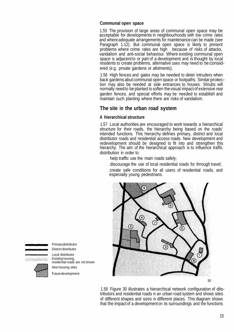
PrimarydistributorDistrict distributor
Local distributorExisting housing,residential roads are not shownNew housing sites
Futuredevelopment
Communal open space
1.55 The provision of large areas of communal open space may beacceptable for developments in neighbourhoods with low crime ratesand where adequate arrangements for maintenance can be made (seeParagraph 1.12). But communal open space is likely to presentproblems where crime rates are high - because of risks of attacks,vandalism and anti-social behaviour. Where existing communal openspace is adjacent to or part of a development and is thought by localresidents to create problems, alternative uses may need to be consid-ered (e.g. private gardens or allotments).1.56 High fences and gates may be needed to deter intruders whenback gardens abut communal open space or footpaths. Similar protec-tion may also be needed at side entrances to houses. Shrubs willnormally need to be planted to soften thevisual impact of extensive reargarden fences, and special efforts may be needed to establish andmaintain such planting where there are risks of vandalism.
The site in the urban road system
A hierarchical structure
1.57 Local authorities are encouraged to work towards a hierarchicalstructure for their roads, the hierarchy being based on the roads’intended functions. This hierarchy defines primary, district and localdistributor roads and residential access roads. New development andredevelopment should be designed to fit into and strengthen thishierarchy. The aim of the hierarchical approach is to influence trafficdistribution in order to:
- help traffic use the main roads safely;- discourage the use of local residential roads for through travel;- create safe conditions for all users of residential roads, and
especially young pedestrians.
30
1.58 Figure 30 illustrates a hierarchical network configuration of dis-tributors and residential roads in an urban road system and shows sitesof different shapes and sizes in different places. This diagram showsthat the impact of a development on its surroundings and the functions
15

16
of roads within a scheme may depend upon the size and location of thesite in relation to thedistributor roads. For example, while sites 1 and 2both gain access from existing residential roads, each will make adifferent impact upon the adjacent roads. Similarly, while sites 3, 4, 5,and 6 all gain access from local distributors, each presents different sitelayout opportunities and different problems regarding the exclusion ofnon-access traffic. Also, a local distributor is an integral part of site 6,while sites 7, 8 and 9 each gain access from district distributors ratherthan, as is preferable, from other residential roads or local distributors.
1.59 Subject to considerations of traffic volume, vehicle access tocommunity facilities may be from residential roads. But where largeservice vehicles are likely to require access to facilities such as shops,it will normally be more sensible for reasons of economy and generalamenity to provide separate road access from the local distributor.1.60 In many existing urban areas a road hierarchy may not be easilyrecognisable. However, it isessential for the local authority to define theintended functions of roads in the local area so that decisions can bemade about the functions of roads within thesite. When assessing thefunctions of roads in the local area it is important to consider not justvehicular movement but the volumes and patterns of movements bypedestrians and cyclists as well.
Movement patterns
1.61 When estimating directions, amounts and types of movement it isnecessaryto consider what changes are likelyto occur over time in thelocation of local facilitiesand in the volumes and typesofvehicular trafficgenerated within thescheme and different parts of the road layout inthelocal area. While it is seldom possible to predict such changes with anycertainty, those which are foreseeable, and especially those which mayaffect the feasibility of future development, must be taken into accountwhen planning the layout and also when considering what impact thescheme itself will have on the surrounding area.
1.62 The volume of vehicular traffic within a scheme will depend onsuch variables as household size and composition, socio-economicstatus, levels of carownership and use of public transport. Itis importantto recognise that these factors change over time, and will vary fromlocation to location. Special considerations will apply where communityfacilities such as schools and shops are served by residential roads.Ideally such factors should form part of the local area planning andtransportation data and it is not envisaged that exhaustive calculationswould be required for each individual housing project.
20mph speed limit zones
1.63 To help reduce the number of road accidents and the severity ofinjuries, theDepartment of Transport (which has to approve any speedlimit below 30mph) will approve 20mph limits in residential areas -
provided drivers are alerted at the entrances to such areas that they areentering a 20mph zone and engineering measures are used to enforcethe lowerspeeds required.28The Department of Transport’s guidelineson such matters will needto be consulted by the local highway authoritywhen a new residential development is located in a 20mph zone or isconsidered eligible for designation as a 20mph zone.1.64 The roads’ intended functions need to be taken into account whenconsidering thedesignation of 20mph zones. Such zones maycontrib-ute to the creation of a hierarchical structure for the loca’ road systemand thereby help to discourage non-access traffic from using residen-tial roads. Section 2 gives guidance on the design measures that needto be used to restrain vehicle speeds.

The Layout Overall
Main objectives2.01 To help create a safe and nuisance-free environment the roadlayout should be designed to ensure that:(a) non-access vehicular traffic finds distributor roads more convenient
to use than residential roads;(b) vehicle flows are low in the immediate vicinity of homes;(c) vehicle speeds are restrained along residential roads.
2.02 The layout configuration required to meet these objectives shouldbe designed to ensure that:(a) residents’ needs for fire, ambulance and other emergency services
can be met promptly;(b) the shortest practicable vehicular routes are provided between
dwellings and points of access to the site;(C) the most direct practicable routes between dwellings are provided
for those who make regular door-to-door collections and deliveries(e.g. refuse collection and milk delivery);
(d) direct vehicular access to as many dwellings as possible is availablefor taxi drivers, mini-bus operators and others who provide door-to-door personal transport services;
(e) residents’ needs for conveniently located public transport facilitiescan be met;
(f) the layout configuration, street names, signs and dwelling number-ing together help strangers to find their way around.
2.03 The measures that are used to restrain vehicle speeds should belocated and designed to:(a) restrain the speeds of all vehicles;(b) ensure that pedestrians, cyclists and drivers and their passengers
are not faced with:(i) unexpected conditions that could constitute safety hazards;(ii) unnecessary discomfort;(iii) avoidable inconvenience;
(C) minimise risks of traffic nuisance from increased acceleration,braking and changing gear, exhaust fumes or vibration;
(d) ensure that the great majority of drivers find acceptable the dis-tances over which they are expected to proceed at low speeds.
2.04 Inter-visibility should be provided to suit the vehicle speeds that arelikely to occur as a result of introducing measures to restrain vehiclespeeds.2.05 To provide safe, secure and convenient routes for pedestrians andcyclists the layout of roads and footpaths should ensure that:(a) drivers are aware on entry and throughout the layout that they are in
surroundings where the needs of pedestrians and cyclists takeprecedence over the free flow of vehicles;
17

18
(b) main routes between the homes, bus stops and community facilities:(i) are as short as possible;(ii) have the easiest practicable gradients - especially for elderly
and disabled people;(iii) are as protected as possible from driving rain, wind and snow;(iv) are well-lit after dark and self-policing by being overlooked by
dwellings or passing traffic;(c) footways are provided where a shared surface would not be appro-
priate;(d) shared surfaces are designed to allow pedestrians, cyclists and
drivers to mix safely.2.06 The road and footpath layout also needs to ensure that:(a) suitable routes are provided for gas, water, electricity, telecommu-
nication and sewerage services underground and adequate spaceis made available for above-ground equipment such as telephonekiosks and sub-stations;
(b) adequate street lighting is provided in all parts of the layout toenhance safety and security for drivers, pedestrians and cyclists.
2.07 To help avoid the danger, nuisance, inconvenience and damagethat can be caused by indiscriminate on-street parking, it is necessaryin design to provide:(a) sufficient numbers of off-street parking spaces for residents’ and
visitors’ cars;(b) spaces for short-term parking by service vehicles and casual callers
on or alongside carriageways which give direct access to dwellings;(c) routes between parking spaces and dwelling entrances or other
destinations that are shorter and more convenient to use than wouldbe the case if parking occurred on carriageways;
(d) parking spaces close to and within sight of the dwellings they areintended to serve.
2.08 Verges, footpath routes and parking areas should be designed toaccommodate trees and shrubs when this would help to enhance thevisual character of the development or provide other benefits such asprivacy and shelter from wind.

Non-access vehicular traffic and vehicle flows
Through routes
2.09 The changes in carriagewayalignment that are needed to restrainvehicle speedsalong residential roads (see Paragraphs 2.29-2.60) willoften be sufficient in themselves to deter non-access traffic. In thesecircumstances, the most convenient practicable vehicular routes maybe provided for residents and visitors - by usinga network configurationof roads such as that illustrated in Figure 31 * Itaims to provide frequentand conveniently distributed access points and allow service vehiclesto move freely between different parts of the site. Safety and ease oftraffic flow will need to be taken into account when determining thenumber and location of access points along distributor and majoraccess roads serving such layouts (see Section 3).2.10 Additional measures would be required if non-access trafficwould not be sufficiently deterred by the speed restraints - for instancebecause of traffic delays along roads outside the site. In these circum-stances, vehicular routes within the site may need to be made signifi-cantly longer than the alternatives outside. Or some routes across thesite may need to be made more tortuous than those outside (Figures 32and 33). In extreme circumstances, a mixture of loop roads and culs-de-sac may be needed to exclude non-access traffic from the site -
either altogether (Figure 34) or in some directions only (Figures 35 and36). The use of one-way streets for these purposes will not normally beappropriate for residential areas. The provision of links which could onlybe used by buses may sometimes need to be considered in thecircumstances illustrated in Figures 34-36. The design of such linkswould need to be carefully considered by the highway authority inconsultation with public transport operators.
Vehicle flows
2.11 It will normally be possible to keep maximum vehicle flows to aminimum and distribute vehicle flows evenly in the layout by consider-ing carefully the configuration of the road layout in relation to the numberand location of access points to the site, the density of buildingdevelopment in different parts of the layout and the location of externalattractions such as centres of shopping, schools and principal trafficroutes.2.12 The means used to restrain vehicle speeds along residentialroadswill normally encourage residentsand visitors to take the shortestpracticable routes when entering and leaving the development. There-fore, vehicle flows would tend to be well-distributed in the layoutsillustrated in Figures 31-36 and maximum vehicle flows would largelydepend upon the numbers of access points provided. For example,with the eight access points illustrated in Figure 31, maximum flows
*This and otherlayouts in thissection are intended to illustratean individual aspectof designin a simplified and diagrammatic manner. They are not intended to be examplesof realisticlayouts.
19

would be no more than around 40 vehicles per hour if there were 320dwellings in the development (assuming one vehicle journey perdwelling in the peak hour), similar building densities in different partsof the area and well-distributed external attractions. But such flowswould increase if the numbers of access points were reduced. Forinstance, they would be up to around 80 vph with only four accesses(Figures 37 and 38), 160 vph with only two accesses (Figures 39 and40) and 320 vph with only one access (Figure 41). Vehicle flows wouldtend to be divided unequally between access points and distributedunevenly in different parts of the road layout if asymmetrical layoutconfigurations and arrangements of access points were used (Figure42).
Access to dwellings
Direct access2.13 For economy, every effort should be made in design to ensure thatmost stretchesof road in the layout directly serve dwellings. As generalguidance, it is suggested that access may normally be provided fromresidential roads serving up to around 300 dwellings. Ways to ensurethat most residential roads serve well under 300 dwellings have beensuggested above.2.14 There may be some places in large developments where vehicleflows are high enough to warrant the avoidance of direct vehicularaccess to dwellings. Such places may occur where several largegroups of dwellings have to be connected to the distributor road by ashort length of road and a single junction (Figure 41). These aresometimes called ‘transitional’ roads. Theyalways form thestem of aT-junction with a distributor road. Such roads should be kept as short aspracticable.
Visual character2.15 To help enhance the visual character of the development, thelayout as a whole should be designed so thatthe fronts of dwellings (notgable walls, fences or garages at theends of back gardens) face moststretches of road. Special efforts will be needed to ensure that housesface onto local distributor and other roads that serve more than around300 dwellings (and which consequently do not provide direct access
20

to dwellings). For example, the residential road layout may need to beextended to provide an access road (or shared driveway) adjacent toand running in parallel with the major road (Figure 43).
2.16 Alternatively, the access road may be connected to the majorroad (Figure 44) provided:(a) the spacing of connections along themajor road is not less than the
minima required for junctions;(b) most drivers do not normally have to park on the major road* (i.e.
assigned and unassigned parking provision for both residents andvisitors is adequate);
(c) drivers of cars and small service vehicles would not have to reverseout onto the major road (i.e. the design of the access road andindividual driveways together allow such vehicles to turn).
2.17 To help enhance the appearance of these layout arrangements,trees should normally be planted between the access road and themajor road. Tree and shrub planting is essential where there wouldotherwise be unrelieved and extensive views of garden fences andscreen walls.
Natural surveillance
2.18 The location of dwellings to face most stretches of roads will alsohelp to enhance security - provided thedwellings are designedin detailso that natural surveillance is possible from their windows. In this way,the layouts illustrated in Figures 43 and 44 would help to enhancesecurity along the major road. Special efforts to provide natural surveil-lance may also be needed along other roads.2.19 Either culs-de-sac, loops or through roads may be designed toenhance security by encouraging natural surveillance. Culs-de-sacmay be effective if they serve only small numbers of houses and are notlinked together by footpaths, and if thehouses are grouped to overlookeach other across the road or a small common open space. Equally,culs-de-sac, loopsor through roads serving larger numbers of housesmay also be effective - with the greater volumes of passing trafficproviding surveillance. However, the rate of traffic flow may be crucial- too little and surveillance may be reduced, too great and residentsmay turn their back on the street.
Alternative means of access
2.20 The road layout should be designed to help minimise risks ofaccess problems for the emergency services and residents arising asa result of vehicle breakdown, road maintenance or the need to gainaccess to services underground. While none of these events are likelyto occur very frequently they may block access or cause inconvenienceunless means can be found to by-pass them.2.21 Risks of such problems arising can mainly be reduced byproviding alternative means of vehicular access - either permanently orfor use in an emergency. This should be the aim wherever the roadlayout serves a significant number of dwellings. When considering therelative merits of these design options it should be borne in mind that:(a) either permanent or emergency alternative means of access can
help to provide direct and convenient routes for pedestrians andcyclists;
Subject to the highway authority’s views about the intended function of the road and itssuitability for occasional parking by refuse and other service vehicles that may choose notto enter the access road.
21

22
(b) the use of loopsand through roads to provide permanent alternativemeans of access will also - compared with culs-de-sac:(i) reduce thenuisance and inconvenience that can be causedby
vehicles reversing and turning,(ii) distribute vehicle flows more evenly over the layout.
2.22 As general guidance, it is suggested that:(a) a road serving up to around 50 dwellings may be either a loop or
through road, a cul-de-sac with a footpath link that could be madeavailable for use by vehicles in an emergency or a cul-de-sacwithout such a footpath link;
(b) a road serving more than around 50 dwellings and up to around 100dwellings should preferably be a loop (Figure 45) or through road,or at least have a footpath link for use by vehicles in an emergency(Figure 46);
(c) for a road serving more than around 100 dwellingsand up to around300 dwellings(i) two points of access should be provided to the part of the site
being served and the road layout should convenientlyconnectthose points of access (Figure 47) or, where only one point ofaccess is available,
(ii) the road layout shOuld form a circuit and there should be theshortest practicable connection between this circuit and thepoint of access (Figure 48).
2.23 Special measures to maintain access may need to be consideredwhen alternative access cannot be provided in the manner describedabove and a road serves more than around 300 dwellings.
Access for service vehicles
2.24 The convenience of those who make regular collections anddeliveries and provide door-to-door personal transport services will beaffected by the road layout configuration. This should be taken intoaccount when planning the layout. For example, the layouts in Figures49-52 all have thesame travel distance from the entry point of the roadto the furthest dwelling. Figures 50-52 however, could, with the samedwelling frontages, serve twice as many dwellings as Figure 49. But inFigures 50 and 51 this could only be achieved at the expense ofdoubling the traffic volume at theentrypoint and in Figure 52 carewouldbe needed to ensure that the flows at each entry/exit point were roughlyequal. Figures 51 and 52, however, have an advantage over Figures49and 50 in halving the distance travelled by service vehicles such asdustcarts and milk floats for the same number of dwellings.

Access for buses2.25 Local public transport operators’ requirements will need to betaken into account at the outset of design when buses are likely to usethe road layout.29 In these circumstances, bus stops should be locatedand designed to ensure that:(a) residents will find them convenient and safe to use (usually near
road junctions, grouped with telephone kiosks and post boxes, withshelter provided from wind and rain, with good street lighting andin places which can be seen from dwelling windows and bypassers-by);
(b) bus drivers will find them convenient to use (usually at straightstretches of kerb - not lay-bys - and in places where parked cars willnotprevent the buses from approaching and departing in a straightline);
(c) when necessary, adequate space is provided for buses to turn orto wait (dimensions and configurations should be determined inconsultation with the local bus operators);
(d) the least possible nuisance is created for residents living in nearbyhouses;
(e) the overall visual character of the road is enhanced (for instance, bycarefully selecting and designing the signs and shelters, by usingany large space required for buses to turn to plant large trees andby integrating all of these features into the overall design conceptfor the road).
Vehicle speeds
Driving speeds2.26 Regardless of statutory speed limits in built-up areas, all driversare legally obliged to drive with caution to suit the prevailing conditions.These conditions are related to road layout, matters of detailed designsuch as the alignment and widths of roads, and to the patterns ofvehicular movement and pedestrian use to be expected on and aroundthe roads. It has to be recognised, however, that many drivers exceedstatutory speed limits - if the road alignment allows them to do so - andsome drivers proceed at speeds exceeding those which suit theprevailing conditions. These considerations need to be taken intoaccount when designing the roads and their surroundings to restrainvehicle speeds.
Visibility2.27 Restricted visibility in the absence of other precautions cannot beconsidered a safe means of reducing vehicle speeds. For safety,drivers must be able to see a potential hazard in time to slow down orstop comfortably before reaching it. It is necessary therefore to con-sider the driver’s line of vision, in both thevertical and horizontal planes,and the stopping distance of the vehicle.2.28 Visibility distances must be adequate for the expected speed ofvehicles. If measures have been taken to keep the speed of mostvehicles below 30mph it may be possible to base visibility on theselowerspeeds. In such cases, likelyvehicle speeds along each stretchof carriageway and at each junction and bend should be consideredseparately - together with the location of any potential obstructions tovisibility such as buildings, planting and summits. Section 3 givesdetailed guidance on visibility considerations in general and particularrequirements for visibility at junctions, on bends and along the edgesof carriageways.
23

Speed restraints2.29 Section 62 of the Highways Act provides a general power toimprove highways; Section 75 of the same Act empowers a highwayauthority to vary the relative widths of the carriagewayand any footway;and Section 77 of the Highways Act 1980 permits the level of a highwayto be raised, lowered or otherwise altered. Specific powers relating toroad humps, including the necessity to post and publish notices, arecontained in Sections 90A to 90F of the Highways Act 1 980.30Highwayauthorities will need to be satisfied that any speed restraint measuresconstructed come within the meaning of the relevant legislation. TheDepartment of Transport’s guidelines for the introduction of 20mphspeed limits may also be relevant (see Paragraphs 1.63 and 1.64).
2.30 The adequacy of speed restraints in this respect and theiracceptability to different road users will depend upon the types ofrestraints used, their spacing and detailed design, the combinedimpact of different types of restraints, the effectiveness of any comple-mentary design measures and the numbers and typesof restraints thathave to be negotiated along the road in question. It is important that thelocations of speed restraints should be clearly apparent to drivers,cyclists and pedestrians during the day and at night.
2.31 Experience of designing speed restraints for new developmentsin this country is limited so far. And evidence from appraisals ofrestraints in use is even more limited. Consequently it is only possiblein this edition of the bulletin to make some general observations aboutthe main considerations that need to be taken into account in designand to describe some of the design options that are currently available.2.32 Localauthorities may wish to encourage theuse of some types ofspeed restraints on a small scale in the first instance, appraise theirbenefits and drawbacks and then produce local design guidance inlight of this experience. Experience gained from introducing speedrestraints along existing roads may also provide relevant information.
Changes in horizontal alignment2.33 An indication of the likely consequences for vehicle speeds ofintroducing significant changes in horizontal alignment is provided byfindings from a study of residential streets with traditional cross-sections and visibility standards.312.34 The study found a clear relationship between vehicle speedsandthe length of the Street between junctions or bends. For straight lengthsof 60m and 100m the findings suggest that the 85 percentile speedswere close to 20mph and 25mph respectively. Over 200m, suchspeeds were well in excess of 30mph.2.35 Vehicle speeds in a small sample of very long culs-de-sac andloop roads were lower than those found along other roads withcomparable lengths. Higher speeds were found along access roadswhich functioned as and had the appearance of distributors.2.36 The study also found that vehicle speeds were re’ated to radii atbends, but the effects of tight radii were not as great as had beenexpected - probably because of drivers cutting corners.2.37 These findings suggest that vehicle speeds in new residentialdevelopments may be effectively restrained by using short culs-de-sac, carriagewayoffsets and junctions or small radius 90 degree bendsto keep unrestricted lengths of roads to a minimum (Figures 53-56).Also, grouped parking spaces may be used in conjunction withcarriageway offsets to break up what would otherwise be excessivelylong stretches of road (Figures 57 and 58).
24

2.38 Mountable shoulders have been used in some developments tohelp reduce thespeeds of cars at bends. The bends have two differentradii - to suit the turning characteristicsof cars and larger vehicles - andthe shoulder is made uncomfortable for car drivers and, to a lesserextent, for the drivers of larger vehicles. This speed restraint has beenused on bends along shared surface roads (Figure 59) and accessroads (roads with footways) (Figure 60).
2.39 Mountable shoulders have also been used to help reduce thespeeds of cars turning at junctions between two shared surface roads(Figure 61). This restraint should not be used for junctions where roadshave footways, because theshoulder may divert pedestrians crossingthe mouth of the stem road onto the carriageway of the through road.
2.40 Chicanes and islands (Figures 62 and 63) are two other changesin horizontal alignment that have been used to restrain speeds. Theireffect on drivers issimilarto that of having to manoeuvre around parkedcars.2.41 To be effective, the lateral displacement of the running lane in achicane must be severe, and the length of thedisplacement should beshort. Similar care is needed in the design of islands. For instance,mountable shoulders should normally be used to restrain the drivingspeeds of cars and the central part of the island should be designedto prevent service vehicles driving over it.2.42 Adequate reductions in vehicle speedswill be feasible in the greatmajority of new developments through the use of shortculs-de-sac andchanges in horizontal alignment alone. These restraints cause the leastpossible discomfort and inconvenience to cyclists, drivers and theirpassengers and to pedestrians usingshared surface roads. Also, theyare familiar in one form or another to all road users today. For thesereasons their use will be appropriate for most new developments.
Changes in vertical alignment2.43 However, it needs to be recognised that site constraints or theoverall design concept for a development may make changes invertical alignment preferable - either in some parts of the layout or asthe main measure used to restrain vehicle speeds. In large develop-ments, changes in vertical alignment may be needed to avoid creatingthe maze-like layout configurations which can result from using onlychanges in horizontal alignment.2.44 Road humps conforming to the Highways (Road Hump) Regula-tions 1990 can be appropriate for both new developments and im-provement schemes.32 The flexibility conferred by the 1990 Regula-tions permits the construction of road humps to form speed tables andraised junctions (i.e. the use of ramps to raise the carriageway level tocreate a plateau).These are the changes in vertical alignment that seem
25

26
most likely to be acceptable to road users. Such humps must be anintegral and acceptable part of the overall design concept - not anafterthought.2.45 It should be noted that the Regulations permit humps to be usedin 20mph zones without many of the warning signs and other restrictionswhich apply to their use on other roads (though these humps - like anyother speed restraint - should be clearly visible to drivers and othersduring the day and at night (see Paragraphs 2.54 and 2.55).2.46 Raised junctions may extend over the whole area of a T-junctionto restrain speeds along the priority road (Figure 64) or at cross roads(see Paragraph 3.38) to restrain speeds in both directions (Figure 65).A series of speed tables may be used to interrupt what would otherwisebe an excessively long stretch of road (see Paragraph 2.56) (Figure 66).Also, where space allows, sheltered parking bays may be providedalong one or both sides of the carriageway and speed tables used toslow speeds in places where footway extensions are located (Figures67 and 68). Speed tables may also be used to emphasise pedestriancrossing places - for instance where a footpath route crosses a road.
2.47 Experience in other countries suggests that raised junctions andspeed tables can be as effective as conventional round topped roadhumps in controlling vehicle speeds.33 However, they have not beenstudied extensively in this country and, until this gap can be filled, it willbe necessary for highway authorities to make estimates based onfindings from British studies of round topped humps.2.48 An indication of the likely effectiveness of changes in verticalalignment can be found from a study of round topped road humps(100mm in height) that were installed along existing residential roads.34
The study found that, before the humps were installed, a large propor-tion of drivers exceeded the 30mph speed limit whereas when thehumps were present less than 5 per cent of drivers did so. Speedsvaried in relation to the spacing of thehumps. For spacings of 60m and100m the 85 percentile speeds were 20mph and 23mph respectively- very similar to the speeds cited in Paragraph 2.34.2.49 The effectiveness of raised junctions and speed tables and theiracceptability to road users will depend on their spacing and matters ofdetailed design such as the height, gradient and profile of the ramps,the length of the raised area and the typesof surfacing materials used.In a broader sense, the overall appearance of these speed restraintsmay also affect their acceptability to road users.2.50 When considering the use of speed tables or kerb to kerb flat toproad humps it should be borne in mind that such arrangements may behazardous for blind and partially sighted people who are unable todistinguish between thecarriageway and the footway. Tactile surfaceslaid in accordance with the Department ofTransport’s advice should beprovided at these and similar locations.
Combined measures2.51 The study described in Paragraphs 2.33-2.36 found that minorreductions in available carriageway width made little difference tospeeds, and drastic ones like those produced by lines of parked carshad onLy a limited effect*. However, a Umfted number of speedmeasurements were also made on thirteen estates with innovative roadlayouts (designed before or shortly after the first edition of this bulletin
* Other studies have found specific carriageway narrowings tobe more effective, particu-larly if angled or involving lateral displacement. Less severe displacementsachieved byparking re-arrangements andcentral islands have only a smalleffect on mean speeds butcan have a larger effecton 85th percentile speeds.36

was published) that included short culs-de-sac, carriageway narrow-ing, sharply curved roads, shared surfaces and a great variety ofcomplementary landscape features.35
2.52 At nearly all points where vehicle speeds were measured, themean speeds were well below 20mph. Though it was not possible toundertake a systematic investigation, the findings suggest that thecombinations of restraintsmay have beeneffective in reducing speeds,and that the effectiveness of restraints may have been enhanced bychanges in pavings, planting and other features which indicated todrivers that they were in residential surroundings where careful drivingat slow speeds was expected - features such as:(a) curving alignments and varying carriageway widths;(b) trees, bollards and buildings forming gateways at road entrances
and at narrowings and delineating changes in direction at 90degree bends, chicanes and islands;
(c) low shrubs and hedges delineating the boundaries between car-riageways and private and common open spaces (see guidance onvisibility in Section 3);
(d) changes in surface materials and edge restraints highlighting thelocation of speed restraints and reducing the apparent widths ofcarriageways.
2.53 The combined visual impact of speed restraints and complemen-tary measures must be an integral part of the overall design concept forthe development.
Indicating potential hazards2.54 Street lighting is necessary to illuminate bends, chicanes, islands,raised junctions, speed tables and road humps and the presence ofthese restraints should also be made conspicuous by the use oflandscape features such as changes in surfacing materials, trees,shrubs or bollards. Road humps need to have warning traffic signserected and placed in accordance with the Highways (Road Hump)Regulations 1990. However, in 20mph zones, these same regulationspermit considerable relaxation as to the traffic signs that need to beerected.2.55 Differences between carriageway surfacing materials must re-main apparent and provide a safe surface for vehicular movement overthe years and also be economical to maintain and remain visuallyacceptable after repairs have been carried out.
Target speeds and spacing of speed restraints
2.56 Driving speeds of 30mph may be justified on grounds of conven-ience or journey time along some local distributor and major accessroads, but such roads are not provided in most residential develop-ments. As a general guide, taking into account all theconsiderations setout in this section, it is suggested that the design of new residentialdevelopments should normally aim to restrain 85th percentile vehiclespeeds to:(a) well below 20mph along shared surface roads - by keeping
unrestrained road lengths to no more than around 40m;(b) about 20mph along minor access roads - by keeping unrestrained
road lengths to no more than around 60m;(C) under30mph along major access roads - by keeping unrestrained
road lengths to no more than around 80m - 120m.
27

28
2.57 On large sites the layout should provide a convenient transitionbetween these roads (Figure 69).2.58 Also, the design should restrain 85th percentile vehicle speeds towell below 20mph immediately outside schools and at any other pointsin the road layout where children may be especially at risk.2.59 Because the road frontage occupied by speed restraints canadversely affect the provision of entrances to driveways, the locationand design of these restraints should be carefully considered whereroads give direct access to dwellings. The careful location of off-streetand on-street parking spaces may also be critical - for, especially atbends and in places where carriageways are narrowed, indiscriminateparking may otherwise block the carriageway.
Shared surface road
Minor access road
Major access road
Speed restraint
Numbers and types of speed restraints2.60 To minimise inconvenience for residents and those who provideessential services, every effort should be made to keep to a minimumthe number of speed restraints that have to be negotiated betweenindividual homes and roads where speeds of 30mph are acceptable -
taking into account the types of restraints that are used and theirconfiguration in relation to each other.
Direction finding2.61 The means used to restrain vehicle speeds, exclude non-accesstraffic and reduce vehicle flows should help to ensure that pedestrians,cyclistsand drivers who are strangers can readily find their way around(see also Paragraph 1.19).2.62 Strangers commonly have difficulty in finding addresses whenlayout configurations are complex and maze-like; street name-platesare poorly sited, parking spaces are in obscure locations away fromthehomes, and where the main dwelling entrances and numbers cannoteasily be identified.2.63 Requirements for street names, dwelling numbering and lightingshould be taken into account when planning the configuration of thelayout as a whole. Dwelling numberingshould be as simple as possiblefor visitors to understand, minimise the need for signposting and beclearly visible from the highway. It may also be necessary to circulatemaps of a new area to those who provide regular and emergencyservices.

Provision for pedestrians and cyclists
Footpath and cycle track links
2.64 Footpath and cycle track links between roads in the layout andbetween the layout and the surrounding area should be created whensuch links would provide routes that are significantly shorter than thosealong the residential roads and when pedestrians and cyclists wouldthereby be able to reach their destinations without having to use heavilytrafficked distributor roads adjacent to the site (Figure 70).2.65 Footpath and cycle track linksshould be kept as short as possible- with the ends intervisible - and the layout and planting should notprovide hiding places for criminals or obscure lighting. Also, wheneverpossible, the road, footpath and cycle track layout should enable suchlinks to be busy and overlooked from dwellings. One layout arrange-ment that achieves these aims without involving the provision offootpath access to dwellings is illustrated in Figure 71.2.66 It shows abutting turning spaces that serve the driveways ofadjacent houses and allow the space from one cul-de-sac to continueinto theother to create a continuous route for pedestrians and cyclists.This arrangement allows pedestrians and cyclists to take direct routesthrough the layout and has theadded advantage of providingsufficientspace to plant relatively large trees. Bollards, planting or other designmeasures are required to prevent vehicles passing through. Differentturning space configurations may be used to create alternative layoutarrangements.2.67 Cycle gaps should be provided where turning spaces abut.37
These gaps may also need to be designed so that they could providethroughaccess for vehicles in an emergency. Arrangements to preventmotor cyclists passing through these gaps may need to be consideredif there is likely to be a significant problem in this respect, but barriersinconvenience pedal cyclists by requiring them to dismount and thevisual character of such arrangements would need to be carefullyconsidered.2.68 Where, space permits, cyclistsare best segregated from pedes-trians. However, where this is not possible, the footpath should bedesigned as a shared unsegregated cycle/footpath to allow cyclists toride along it.38 Section 3 contains relevant guidance.
Shared surface roads2.69 The layouts described so far in this section may all be achievedwith access roads (roads with footways). Shared surface roads mayalso be used if carefully designed (see Paragraphs 1.42-1.46).2.70 As a general guide, it is suggested that shared surface roads maynormally serve up to around 25 dwellings in a cul-de-sac and around50 dwellings where junctions with roads with footways are located ateach end of the shared surface.* These roads should be designed toprovide:(a) tight kerb radii and/or a ramp at the entrance and any changes in
alignment that may be necessary to restrain driving speeds to wellbelow 20mph (special requirements for thedesign of junctions withdistributor roads are given in Section 3);
(b) a surface that does not give the impression of being divided into acarriageway and footways (i.e. there should be no continuous
* Shared driveways(unadopted pavedareas serving the drivewaysofhouses) shouldserve
no more than five houses (see Paragraph 2.81).
29

height differences in the cross section of the road). Spaces freefrom vehicular traffic may be provided (e.g. by using bollards toexclude vehicles from a play area or visibility splay). Changes insurfacing materials and colours may also be used (e.g. to helpdemarcate parking areas or keep vehicles away from windows anddwelling entrancesor as complementary measures to help restrainvehicle speeds). Surfacing materials should be selected to suitboth pedestrian and vehicular traffic in places where joint use isintended;
(c) a surface wide enough to allow pedestrians and vehicles to passcomfortably and vehicles to manoeuvre (Figure 72);
(d) clearly identifiable spaces to accommodate cars and othervehiclesthat need to be parked outside house curtilages (Figure 73);
30

(e) space between the shared surface and any adjacent entrances todwellings or garages - to allow emerging pedestrians or drivers tosee and be seen by approaching traffic;
(f) intervisibility between pedestrians and approaching vehiclesthroughout, and especially where footways, footpaths and ac-cesses meet the shared surface;
(g) sufficient street lighting to enable road users to see potentialobstacles and each other after dark;
(h) routes for services beneath or adjacent to the shared surface (seeParagraphs 2.76-2.81).
2.71 Differences between the visual character of shared surface roadsand roads with footways should be further emphasised by the use ofdesign features such as closely spaced buildings or gateways atentrances to shared surfaces (Figure 74); trees located to helpdemar-cate parking areas or pedestrian routes (Figure 75); centre or offsetdrainage channels; contrasting paving materials and other elementssuch as ground cover shrubs planted in verges. The edge detailsaround shared surfaces should normally be in contrasting materialsand significantly lower in height than those used along access roads.
75
31

32
Verges and planting
2.72 Planted verges may be used to discourage children from step-ping off footways along thebusiest major access and distributor roadsor to strongly discourage drivers from parking on footways or otherareas alongside carriageways. Also, when a publicly adopted andmaintained verge instead of a footway isneeded to make provision forservices underground or to allow for vehicles to overhang, it may bepossible to enhance the visual character of the development byplanting appropriate shrubs in the verge. Shrub species and anyproposals to make such verges wide enough to accommodate treesshould be agreed with the services providers.
2.73 Sizes of trees and shrubs when mature and their location in thelayout should be considered in relation to requirements for visibility,street lighting and daylight and sunlight in dwellings and gardens. Also,trees located in paved areas should not present hazards for blind andpartially sighted people.
Common open space2.74 Common open space - especially play areas - should be locatednear busy footways or footpaths, be clearly visible from neighbouringdwellings and be well-lit during hours of darkness. The design shouldnot provide secluded spaces or possible hiding places. The provisionof a defined footpath with good artificial lighting will encourage peoplewalking through thearea to use that route. This can help to improve thenatural surveillance of the open space, and of houses backing onto it,whilst people who stray from the paths are more likely to be noticed.2.75 Bearing in mind that requirements for casual surveillance need tobe balanced with other important housing considerations such as theprovision of adequate privacy and the use of trees and shrubs toenhance the visual character of the development, it is suggested thatthe main entrance doors, windows and side entrance gates to thehouses should be visible to neighbours or passers-by.
Statutory and other services
General requirements
2.76 As well as making provision for pedestrian and vehicular move-mentmost residential roads and footpaths provide routes for statutoryand other services underground.39These services are an essential andintegral part of the layout and their efficiency and safety in use are vital.The availability and location of existing services must be identified at theoutset and those who will provide the new services must be consultedat the earliest stage of design, their requirements co-ordinated in thelayout, and a balance struck between their needs and other housingobjectives.The locations of existing trees and shrubs and proposals fornew planting will require special consideration.2.77 It is in the interests of residents that all services should beeconomical to install and maintain. The provision of adequate accessfor operational purposes is essential for residents in the scheme andoften for users elsewhere as well.2.78 Unnecessary capital expenditure and costs in use may be in-curred if services, roads and footpaths and the location of trees andshrubs are not planned together and with care for matters of detail. Inplaces where the most effective form of provision may be a multi-wayduct or common trench for all underground services, such an optionmust be jointly considered at an early stage in design.

Preferred routes
2.79 Preferred routes for services are beneath publicly adopted andmaintained footways, footpaths, verges or carriageways. Where serv-ices are to be laid in a publicly adopted but privately maintained vergeadjacent to the carriageway:(a) the location of the verge should be indicated by markers such as
setts or bricks at private driveway or footpath crossings;(b) the status of the verge should be made clear to purchasers in the
conveyancing of the dwelling - to make them aware that:(i) they should not build wallsor fences or plant treesor shrubs on
the verge;(ii) services providers may need to excavate their services;(iii) if a cable is installed in such a verge, it could be a potential
hazard to occupants who dig indiscriminately over the verge.2.80 Where no alternative exists it may be possible to install servicestrips in land that is not publicly adopted providing early discussionsare held with service providers and thehighway authority and adequatesafeguards are provided. Conveyancing documents must incorporateperpetual rights for service providers within the service strip. Inaddition, the provisions set out in Paragraph 2.79 (a) and (b) must beincluded.
Shared driveways
2.81 When unadopted shared driveways are to be used, servicesproviders will not normally lay their mains beyond the highway bound-ary. Services will then be provided from the main, with the servicecables/pipes laid under the surface of the shared driveway and theninto each property. The acceptability of shared driveways dependsupon the following considerations:(a) no more than five dwellings should be served by the shared
driveway (this will generally come within the technical limitations ofservicing from a main laid in the highway boundary);
(b) where for technical reasons services cannot be supplied from amain laid in thehighway, thedevelopermust agree with the servicesproviders on where and how their mains are to be laid (this mayinvolve the installation of ducts, jointing pits or chambers at thedevelopers expense).
Lighting
2.82 Lighting must be planned as an integral part of the layout ofaccess and shared surface roads, shared driveways, footpaths andbus stops and in conjunction with the location and anticipated growthof trees. These spaces must be well-lit, not only to help people to seewhere they are going but also to reduce risks of night-time accidents;assist in the protection of property; discourage crime and vandalism;make residents feel secure and enhance the appearance of thescheme after dark. The standard of lighting provided should ensurethat shadows are avoided in places where pedestrians would otherwisebe vulnerable. Also, lighting columns and wall-mounted and otherfittings normally need to be as resistant to vandalism as possible andbe placed in positions which minimise risks of damage by vehicles.Detailed advice on such matters is contained in British Standard 5489Parts 1,3 and 940
2.83 Lighting columns and fittings also make a major impact on theappearance of thescheme during day-time and should be planned aspart of the overall design concept. Highway authorities’ approved
33

34
ranges of columns and fittings should be chosen with this aspect inmind as well as lighting efficiency, running costs and maintenancerequirements.
Provision for parking
On-street and off-street provision
2.84 Vehicles parked indiscriminately on carriageways can blockaccess to dwellings and cause other hazards by masking road usersfrom each other. Thus the layout should make effective provision for off-street parking. However, there will always be casual callers and servicevehicle drivers who find it more convenient to park on thecarriageway.Consequently, requirements for on-street parking must also be plannedfor in the design.2.85 To achieve this aim successfully it is necessary to design as awhole the total space that will be used by vehicles to manoeuvre andpark - taking into account thewidth and alignment of the carriageways,the spacing and widths of entrances to driveways, the widths andlengths of the driveways and the widths and depths of garages, carports and hardstandings. Geometric characteristicsof vehicles turningare given in Appendix 1 and some dimensions for driveways, parkingbays and communal parking areas are given in Section 3.2.86 The general considerations that planning authorities should takeinto account when working out their requirements for the total numberof parking spaces to be provided are set out in Section 4.
Parking activities2.87 Six main kinds of parking activities should be taken into accountwhen considering the location of spaces and the suitability of variousparking arrangements:
Residents’ cars - long-stay (e.g. overnight or during repair) andshort-term (e.g. at lunch time or during car washing)Visitors’ cars - long-stay (e.g. for the evening or a weekend) andshort-term (e.g. to deliver a message or have lunch)Service vehicles - long-stay (e.g. furniture removals vans or build-ers’ lorries) and short-term (e.g. refuse collection or milk delivery).
Location of parking spaces2.88 Experience suggests that few drivers are prepared to use parkingspaces more than a few metres away from their destinations, and thereare increased risks of theft and vandalism when cars are parked out ofsight. Consequently, the aim should be to make each small group ofdwellings self-sufficient with regard to its off-street and on-streetparking provision by locating:(a) garages, car ports and hardstandings within dwelling curtilages
(Figure 76);(b) grouped garages, car ports and hardstandings immediately out-
side the entrances of the houses or flats they are intended to serveand within sight of kitchen or living room windows (Figure 77) - or,when there is no direct roadaccess, at theends of access footpathswithin sight of dwellings and passers-by;
(c) casual parking spaces for visitors’ cars and service vehicles as anintegral part of the carriageway layout immediately outside or inproximity to the dwellings they are intended to serve.

2.89 It should be possible for a wheelchair to be pushed from vehiclesetting-down points to all dwelling entrances without the need tonegotiate steps. Specially reserved off-street parking spaces shouldbe located close to all dwellings designedfor occupation by wheelchairusers. Other special parking arrangements for disabled people, forexample restricting the use of specific parking bays to holders of officialorange badges, are not recommended.2.90 There may also be special requirements in some places fortemporary parking associated with the renewal and maintenance ofservices - for example, outside an electricity sub-station. Those respon-sible for providing services must be consulted at the outset of design.
35

2.91 Though parked cars must inevitably interfere with intervisibilitybetween pedestrians and drivers in places close to the entrances toprivate drives and in grouped parking areas, care will be needed toensure that they do not obscure visibility on bends and at junctions.
2.92 The local fire service should be consulted about their require-ments,41 bearing in mind that adequate means of access are requiredto ensure that residents’ lives are not placed at risk and that the safetyof fire fighters is not jeopardised. Two fire appliances together with a firecar will attend most incidents, and the possibility of subsequentattendances by the police and ambulance service should be recog-nised.2.93 Access points for refuse vehicles should not normally be furtheraway than about 25m from dustbin collection points in houses and 9mfrom refuse storage chambers in flats.42 Local authorities should beconsulted about their requirements.
Allocation and control
2.94 Privately maintained and managed grouped parking spacessuch as those provided to serve blocks of flats should be locatedbetween the road (or privately maintained driveway) and the buildingentrances, or immediately opposite. It may in addition be necessary tolocate, allocate and control the spaces so that residents are givenpriority for those closest to their homes. Such measures may involveproviding clear markings on the ground, signs or the protection ofspaces with lockable parking posts (Figure 78).2.95 It may also be necessary to provide parking deterrents such ashigh kerbs, low walls, closely spaced bollards, railings or deterrentsurfacing to prevent parking on footpaths or planted areas.2.96 Special problems arise where grouped hardstandings must belocated further away from buildings than is required for access byservice and emergency vehicles. The service access routes requiredin these situations will be used and sometimes blocked by residents’and visitors’ cars unless formal controls such as lockable posts, gatesor chain barriers are used at the entrance to the routes.2.97 It must be emphasised, however, that all such formal methods ofcontrol are normally only feasible when the roads or driveways areunadopted and privately maintained and managed. They are also,normally, visually intrusive and difficult to enforce. It is essentialtherefore to make every effort in design to provide well-located parkingspaces both for residents and for service vehicles.
Visual character
2.98 To enhance the visual character of large grouped parking areas,care should be taken when selecting pavings and means to demarcateindividual parking spaces. The visual impact of large areas of pavingmay be reduced by usinga variety of materials for theparking spaces,forecourts, drainage channels and running lanes in theaccess aisles.2.99 Parking areas provide an important opportunity to plant trees orshrubs (especially the larger varieties) and thereby enhance theoverallvisual character of a development. Also, though most people areprepared to tolerate the sight of cars in residential areas, trees andshrubs can reduce their visual impact. Thus the layout as a wholeshould be planned to allow sufficient space for such planting - whilst atthe same time allowing (for security) the cars to be seen by passers-byor from houses.
36

The Layout in Detail
Main objectives3.01 Decisions about the layout of carriageways, bends, junctions andturning spaces should take into account the arrangements that havebeen made to minimise vehicle flows, reduce vehicle speeds and makeprovision for parking. To provide for vehicular movement within such acontext and to minimise the damage and nuisance which can be causedby vehicles the widths and alignments of carriageways should bedesigned to take into account:(a) the expected volumes and speeds of vehicular traffic;(b) the frequency with which various types of vehicles need to pass each
other;(c) the provision made for off-street and on-street parking;(d) the availability of alternative means of access to dwellings to help
ensure that carriageways are not blocked by incidents such asvehicle breakdown and carriageway repairs.
3.02 The spacing and layout of junctions should be designed to take intoaccount:(a) the types and numbers of vehicles likely to use the junction;(b) the directions of movement at the junction;(c) the extent to which delays may be caused by conflicting vehicular
movement at junctions with distributor roads.3.03 The spacing and layout of turning spaces should be designed totake into account;(a) the sizes of vehicles expected to use them;(b) the need to avoid vehicles having to reverse over long distances;(c) the need to prevent parking in turning bays by the careful location of
adjacent off-street parking provision.3.04 Visibility at bends, junctions and summits should be sufficient toenable drivers to stop if necessary to avoid collision. Visibility at junctionsshould be sufficient to enable drivers entering the priority road to do sosafely and to be seen by other vehicles approaching the junction.
3.05 Footways should be designed to take into account:(a) the functions of adjacent carriageways;(b) requirements for statutory and other services;(c) the amount of pedestrian movement expected;(d) requirements of people with disabilities;(e) the space occupied by street furniture such as lamp posts and
regular obstructions such as refuse bags waiting to be collected.3.06 Such considerations will also normally need to be taken intoaccount in the design of footpaths. In addition, footpaths normally needto make provision for the movement of cyclists and may need to bedesigned to provide access to dwellings for the emergency services andallow for the movement of maintenance vehicles.
37

3.07 Verges should be designed to take into account any requirementsfor services underground, clearances for vehicles to overhang or provi-sion for trees and shrubs to be planted.3.08 The layout and dimensions of on-street parking spaces, parkingbays and forecourts in grouped parking areas and parking spaces withindwelling curtilages should ensure they are convenient to use. Groupedparking bays should be demarcated to help avoid the waste of space andobstructions that can be caused by indiscriminate parking.
38

Carriageways
Vehicles3.09 The dimensions of carriageways, junctions and turning spacesmust be determined in part by the size and geometric characteristicsof vehicles. Not all types of vehicles are likely to use residential roads,and those which do may not need access to all partsof a site. For suchreasons a range of vehicle types and their turning and manoeuvringcharacteristics are given in Appendix 1. Theyhave been chosen fromstudies of the typesof vehicles whichmay generally be expected to useresidential roads.* Each vehicle represents the larger size range of itstype and residential roads designed to accommodate them shouldtherefore be more than adequate for the majority of other vehicles.**The space required for vehicles to move and manoeuvre will also be
79 A 5.5m width allows all vehicles to pass influenced by the context in which they operate and the additionaleach other, withanoverall toleranceof 0.5m for
factors outlined below will need to be considered.the largest vehicles but with ample clearancefor all others. Given the infrequency of largevehicles on residential roads, this width will Tolerancesnormallybethemaximumrequiredtocope withresidentialtraffic. Below5.5m thecarriageway 3.10 The ease, and hence the speed, with which vehicles may movewillbetoonarrowforthe freemovementof large along carriagewaysdepends in part upon thetolerances available bothservice vehicles suchaspantechnicons. Where between vehicles and between vehicles and kerbs. On distributorsuch vehicles are allowed access passing roads where ease of traffic flow is of high priority and where drivers willplaces mayberequired. Thecarriagewaywidth normally expect to be able to proceed at speeds of up to 30mphrequired between passing places will thendependupon thecombinationsofvehicle types
carriageway widths will need to be in accordance with the recommen-expected; the frequency with which vehicles dations given in Roads and Traffic in Urban Areas.45
maymeeteachotherandthedelaywhichmay 3.11 On residential roads however, where traffic flows are light andbe caused to traffic movement. These factorsmay be expected to varywith traffic volume, where journey distances are short, drivers may be expected to accept
smaller tolerances consistent with the aim of restraining vehicle speeds80 At4.8mthecarriagewaywillaiowa widecar and encouraging careful driving.to pass a large service vehicle such as apantechnicon withanoveralltoleranceof 0.5m, 3.12 Whether ornot smaller tolerances will cause unacceptable delay,and traffic may therefore stiil be regarded as reduce safety, or result in damage to tootways and verges, will dependbeing in free flow, upon the types and volumes of traffic, the design of the carriageway
surrounds and the distances over which drivers have to proceed. Such81 At 4. Im the carriagewaywiil be toonarrow factors may vary considerably within a layout. The tolerances providedfor large service vehicles such as apantechnicons to pass vehicles other than by various carriagewaywidths for the vehicles listed in Appendix 1arecyclists. It does however allow wide cars to shown in Figures 79-82.pass each other with a tolerance of O.5m.
3.13 As indicated in Figure 79, a width of 5.5m is normally required toHence, while being more restrictive on themovementoflargevehicles, a width of4. imwill enable the largest vehicles to pass each other. Most vehicles, however,still provide two-way flow for the majority of will be private cars and traffic capacity will rarely be a critical issue evenresidential traffic. Below 4m the carriageway in larger schemes. For example a 5.5m carriageway collecting trafficwill be too narrow for private cars comfortably from around 300 dwellings is likely to have a capacity far greater thanto pass each other except at very low speed that required, even at peak times. Such spare capacity should enableand may be uncomfortable for cyclists in carriageways to be narrowed in places to reduce the road area and itsconjunction with large vehicles. Widths oflessthan 4m therefore should be regarded as visual impact, preserve existing features such as trees or to comple-catering only forsingle-file traffic. ment speed restraints (see Section 2).
82 The choiceof width below 4m willdependlargelyupon the frequencyandease with which * The vehicles illustrated in Appendix 1 do not include the largest delivery vehicle whichcyclists andcarsmayneedtopass each other. could theoretically be used. For example, rigid vehicles can be constructed up to 1 2m longIt is suggested that 3m be regarded as the with a 7.5m wheelbase. Because of their size and onerous turning and manoeuvringminimum width between passing bays on a requirements such vehicles are likely to be used primarily for inter-depot long-distance
travel rather than for domestic deliveries, and have therefore not been taken into accountsingle-tracksystem, but where narrowsections in this bulletin. Also,Appendix 1 does not include examplesofbuses. Local publictransportare introducedsolelyaspinchpointsa widthof operators should be consulted about the turning and manoeuvring characteristics of the2. 75m will normally be adequate to allow all busesthey proposeto use. Dimensional data for buses is alsoavailable in ‘Roads andTrafficvehicles topass through on their own. Widths in Urban Areas’ and in Local Transport Note 1/91 43
below 2. 75m may, however, be consideredwhereprivate carsonlyareallowedaccess, for ** A possible exception to this is the fire appliance. The vehicle selected is of the typeexample in driveways. In such circumstances normally used fordwellings with floor levels up to 9m above ground. For medium and high-clearances will be necessary to allow rise developments turn-table ladders and/or hydraulic platforms may be required. Suchpassengersand drivers togetoutofthe vehicle vehicleswill have larger turning and manoeuvring requirements and it is essentialto consultat rest. the local fire service (See also Fire Prevention Note 1/70).44
39

3.14 For the first edition of this bulletin, carriageway capacity studieswere conducted at theTransport and Road Research Laboratory usingsingle-track roads with passing places.46 These tests indicate that withpassing bays of sufficient size and frequencyand with visual continuitybetween successive bays, undue delayor inconvenience to traffic is notcaused, even where fairly high vehicle flows are carried. Requirementsfor visual continuity between passing places are given in Appendix 2.It is also essential to take into account any possible hazards forpedestrians or risks of blocked access as a result of on-street parkingor repairs to roads and services underground. The highway authorityshould be consulted about their requirements regarding the use anddesign of single-track roads with passing places. Guidance in theremainder of this section is mainly concerned with the design of othertypes of residential roads.
On-street parking3.15 Provision for off-street and on-street parking has been discussedin Section 2, and is a crucial factor when determining the width ofcarriageway required. Experience suggests that, wherever roads givedirect access to dwellings, the carriageways are invariably used forparking by casual callers and service vehicles. Thus, as a generalguide, in those locations and in any other places where parking byservice vehicles will normally occur on the carriageway, a minimumcarriageway width of 5.5m should be provided to allow one servicevehicle to pass another that is parked. Unassigned parallel parkingspaces that are contiguous with the carriageway may be within theminimum width of 5.5m - provided such spaces are located to allow aclear route and passing places for service vehicles.3.16 A carriageway width of 5.5m will normally be sufficient to allowcars to manoeuvre around vehicles parked on thecarriageway in orderto get into and out of private drives. But dimensions for kerb radii, drivewidths and gateways at the entrances to private drives must take intoaccount the space that will be available for turning on the carriageway.3.17 Along stretches of roads which do not give direct access todwellings, the carriageway width may normally be determined byconsiderations of moving traffic and the availability of passing places(Figure 83). As a general guide, it is suggested that carriagewaywidthsin places where dwellings are not directly served may normally be asfollows:
Arround Arround Up to
Carriageway width (m) 5.5 4.8 4.1
Bround No. dwellings served 50-300 25-50 25
Carriageway narro wings3.18 Carriageway narrowings may be less than 4.1 m, however, specialattention must be paid to the needs of cyclists in these circumstances.Such narrowings will place restraints upon drivers which could causedelay and frustration and may result in actions which could jeopardizethesafety of cyclists. These considerations must be taken into accountwhen determining the extent to which thecarriageway isnarrowed andthe distance over which it occurs.
3.19 Over long distances, such as between passing bays on a single-track system there may be a tendency for cars to attempt to passcyclists on he narrowed section. Little is known about the safe toler-ances required for these movements but, for the first edition of thisbulletin, some studies were carried out by the Transport and Road
40

Research Laboratory on the reactions of cyclists to passing and beingovertaken by cars on carriageways of different widths.47 Virtually allcyclists taking part in the experiments found a carriageway width of3.25m to be acceptable for such movements to occur, with themajoritybeing satisfied with a width of 3m.3.20 As general guidance, it is suggested that carriageways maynormally be narrowed to 3m widefor a length of no more than about 1 5mto help solve a site problem (e.g. to preservea tree) or as a complemen-tary measure to help restrain vehicle speeds (see Section 2). Also,longer stretches may be acceptable subject to the agreement of thehighway authority regarding matters such as intervisibility, the locationof passing bays and provision of footways or footpaths to help ensurethat pedestrians do not have to walk along the carriageway.
Emergency access3.21 The Home Office currently recommends a minimum carriagewaywidth of 3.66m for access roads and this advice is also incorporated inBritish Standard 5588: Part 1.48 This width was specified, however, notonly to enable the fire appliance to proceed at a reasonable pace butalso to allow for operating space around it at the scene of the fire.Discussions with the Home Office have suggested that simplyto reachthe scene of the fire, carriageways as narrow as 2.75m may beacceptable to the fire service, provided that roads can be kept clear ofparked cars. Fire appliances need to be able to approach to a point thatis within 45 metres of a suitable entrance to any dwelling. In all casesit is essential that early discussions are held with the local fire service.
Blockages3.22 A carriageway width of 5.5m is sufficient to allow a 3m wide laneto remain open in the event of a vehicle breakdown and it allows forpatching and minor excavations to be undertaken in the remaining 2.5mwide lane. To meetother eventualities (for example to provide workingspace for more extensive excavations) the overall width available cannormally be increased by using temporarily a part of the area that isusually occupied by the footways or verges alongside. Any servicesbeneath would need to be temporarily protected.
3.23 Thus it should not normally be necessary to use carriagewaywidths greater than 5.5mfor residential roads in order maintain accesswhen vehicles breakdown or repairs to roads or services are needed.And narrower carriagewaywidths may be acceptable in places whereadjacent footways or verges may be used to by-pass blockages.However, when they do occur, such events may cause inconvenienceand damage to footways and verges and this should be taken intoaccount in the design of those parts of the road layout where largenumbers of dwellings are served.3.24 In exceptionallybusy partsof the residential road layout it may berelevant to minimise the need for excavations by locating undergroundservices (including drainage) outside the carriageway.3.25 Where carriageways allow only for single-file traffic in places andlarge numbers of dwellings are served it will normally be essential forthe road layout to provide alternative means of vehicular access - eitherpermanently or for use in an emergency (see Paragraphs 2.20-2.23).
Widening on bends
3.26 The carriageway widths required on bends involve considera-tions similar to those listed above butallowance must also be made forincreases in thewidth of thepaths described by vehicles when turning.
41

42
The extent of such increases will depend upon the radius of the bendand the length of thevehicles. Figure 1 in Appendix 1 shows thewidthsof the wheeltracks and body overhangs for various types of vehiclesturning around various radii. With the criteria listed above this data maybe used to determine whether and to what extent carriagewaywideningmay be necessary.3.27 As an example of the data applied, Figure 84 shows a carriage-way width of 5.5m widened to allow for two pantechnicons to pass ona bend with a 30m outer radius. The carriageway width at its widest ismade up from the swept path of the vehicle on the inside lane, thetolerances normally provided on the5.5m straight section, and the pathdescribed by thewheels of the vehicle on theoutside lane. In the latterthevehicle body has beenallowed to overhang the kerbs and, while thismay be permissible in situations where large vehicles are unlikely to befrequent, the body overhang must always be taken into account whendetermining the location and widths of footways, lighting columns, etc.Dimensions x and y are taken from Figure 1 in Appendix 1.
3.28 In this example, only the inner part of thebend has beenwidened.Widening the outer part of the bend would give the same effectivecarriageway width, but on tight bends could encourage the tendencyfor vehicles on the outside lane to cross over the carriageway ratherthan keep close to thekerb line. It should also be noted that a distanceof 1 2m has been allowed for the realignment of each vehicle beyond itstangent point. This is taken from Figure 2 in Appendix 1 and allows forthe vehicle to realign from its tightest turn. It should therefore cope withany larger radii which may be provided.3.29 Figure 84 is intended only to illustrate how the basic data may beapplied when a decision has been made about the types of vehicleswhich may need to pass on the bend. This may vary according to theamount of traffic on the road, and the need for widening may also beinfluenced by the amount of forward visibility provided between pass-ing places on each side of the bend. On very lightly-trafficked roads,the chances of two large service vehicles such as pantechnicons orbuses needing to pass on the bend may be sufficiently remote to makewidening to theextent shown in Figure 84 unnecessary. Similarly whereadequate forward visibility is provided between oncoming vehicles itwill be possible for large vehicles to wait until the bend is clear and touse part of theopposite lane when turning. As shown in Figure 85 evenwith a 15m outer curve radius a pantechnicon can turn on a 5.5mcarriageway without any widening and without using the whole of thecarriageway width. Dimensions x and y are taken from Figure 1 inAppendix 1. The possibility of using mountable shoulders to helprestrain vehicle speeds at 90 degree bends is suggested in Part 2.
3.30 In places where the bend gives direct access to dwellings it willbe necessaryto allow fora service vehicle to pass another that is parkedon the carriageway.3.31 As a general guide, it is suggested that carriageway widening isnormally needed to the followingextent on bends curving through morethan 10 degrees along roads serving over 25 dwellings (widening
Centre line radius (m) 20 30 40 50 60 80 Min. widening (m) 0.80 0.40 0.35 0.25 0.20 0.15
should be on both sides of the curve, or on the inside):

Gradients
3.32 While the need to avoid excessive cut-and-fill may often justify theuse of steep gradients, regard must be paid to the difficultieswhich mayarise in icy conditions and to their effects on vehicle speedsparticularlyon bends and at junctions. Steep carriageway gradients will alsogenerally result in steep footway gradients that may cause difficultiesforelderly and disabled people. On sites with significant gradients it willnormally be necessary to consider carefully (and show on drawings) therelative levels of house entrances, garage floors, hardstandings, drive-ways, paths and adjoining roads in order to determine the practicalityof the layout.3.33 Where changes in gradients occur, vertical curves will normallybe required at summits and valleys both for ease and comfort of drivingand also, at summits, to ensure adequate forward visibility along thecarriageway (Figures 86-88).
43

44
3.34 The length of curve required will depend upon the expectedspeed of vehicles, the angle of change between gradients and, atsummits, the height from the carriagewayabove which clear visibility isrequired. For residential roads, a 600mm height is recommended(Figure 89) to provide visibility between drivers and young childpedestrians (see Paragraphs 3.56-3.59). Requirements for comfortshould take into account the design measures introduced to restraindriving speeds (see Section 2).
3.35 As general guidance, it is suggested that:(a) the gradient of thenon-priority road at a junction should, whenever
possible, notexceed 5% when rising towards the priority road or 4%when falling to the priority road - for a distance of at least twice thekerb radius;
(b) whenever possible, the gradient of a shared surface road shouldnot exceed 7%.
Junctions
Traffic movements
3.36 Junctions by definition involve cross traffic and/or convergingtraffic movements and they are therefore potential points of hazard.There are considerations however for residential roads which do notusually apply to distributor roads and which make road layout con-straints less onerous.
3.37 When the residential road layout is designed to exclude non-access traffic the vast majority of vehicle journeys will be into or out ofthe layout rather than between origins and destinations within thelayout. The prime exceptions to this being vehicles which have to callat a number of dwellings,e.g. for refuse collection and milk delivery. Themain pattern of movement around junctions may be easily predictedand will normally be less complex than on roads carrying non-accesstraffic. Moreover, the exclusion of non-access traffic may create ahierarchy of traffic volumes within the layout - with volumes beinghighest at the entry point and decreasing with each successivejunction. These factors have important implications for the generalconfiguration, spacing and detailed layouts of junctions.
Configuration3.38 Cross roads: Cross roads are generally regarded as the mostdangerous form of junction, largely because they imply cross trafficmovement (Figure 90). They should therefore normally be avoided.There may however be situations in which cross traffic will be virtuallynon-existent, for example in a short cul-de-sac layout (Figure 91), andtheir use should not be automatically discounted at the lower end of aroad hierarchy where vehicle flows and speeds are low and whereraised junctions are used to restrain vehicle speeds.

3.39 As the scale of the layout increases however, additional precau-tions may be necessary both to deal with any potential increase in crosstraffic movement and to control the movement of turning traffic. The twomost effective means of doingthis are either to provide an island (Figure92) or to stagger the junction (Figure 93). Mini roundabouts as de-scribed in Department Standard TD16/84 49 and Departmental AdviceNote 42/8450 may also be used when space permits and the require-ments for signing and location suit the landscape concept for thedevelopment and allow other important housing design objectives to bemet.3.40 For staggered cross roads to work effectively they should nor-mally be staggered by one carriageway width, and more when a largeamount of cross traffic is envisaged, It is also suggested that right/leftstaggers should be provided in preference to left/right wherever it islikely that traffic would be turning into the side roads from eitherdirection. This is to avoid the possibility of hooking movements (Figure94) which can cause delay or collision.
3.41 T-junctions: Two basic forms of 1-junction may be identifieddepending upon whether the major traffic flow is on the side (non-priority) road or the through (priority) road. The chief characteristic oftheformer (Figure 95) is that it automatically slows downthemajor trafficflow. It may therefore be used with advantage close to the entry pointof the residential road layout and/or where anychange in road characteror traffic speed is required within the layout. Because of the directionof traffic movement determined by the layout as a whole, it is likely thatthe amount of cross traffic will be negligible. But there will be acorresponding increase in theamount of turning movements and it maybe necessary to guard against conflicts by providing priority markingsor islands where substantial volumes of traffic are expected.3.42 Priority markings may also need to be considered for safety andconvenience where the major flow is on the priority road (Figure 96) -
except at the lower levels of the system where both speeds and trafficvolumes can be kept low.3.43 Y-junctions: V-junctions are uncommon in residential road layoutslargely because of the awkward shape of the land parcels which theycreate. Such junctions should normally have priority markings or islandsexcept at the lower levels of the system.3.44 As a general guide, it is suggested that non-priority roads servingmore than around 100 dwellings should whenever possible join priorityroads at an angle of 90 degrees, and be straight for a length of at leasttwice the kerb radius. Other non-priority roads may, if necessary, meetthe priority road at an angle within 10 degrees of a right angle.
Spacing3.45 The frequency of junctions along distributor roads is often animportant determinant of the ease of traffic flow and of the ease withwhich drivers may proceed at a constant speed safely and withoutinterruption. Generally, the closer the junction spacing, the morefrequent the hold-ups to through traffic and the greater the chance oftraffic build-up and accidentsoccurring. For such reasons thespacingof junctions along distributor roads will normally need to be in accord-ance with those recommended in Roads and Traffic in Urban Areas.Within the residential road layout however such considerations areseldom critical and it is important that decisions on the spacing ofjunctions be made with regard to theeffect they have on the economicuse of land.
45

46
3.46 Generally, the block spacing needed to provide adequate day-light and sunlight and to give privacy between dwellings will lead tospacings of at least 30-40m between adjacent junctions. There may beplaces however where closer junction spacing would enable land to beused for housing that might otherwise be wasted. It is necessary,however, to avoid the junction being blocked by traffic building up at theexit to a local distributor. The likelihood of this will depend upon theamount of traffic both on the residential road and on the local distributor,factors which may vary widely from scheme to scheme. As a generalguide, it is suggested that:(a) where the priority road serves no more than around 100 dwellings
there need be no restrictions on junction spacing - and cross-roadsmay be used;
(b) where between around 100 and 300 dwellings are served by thepriority road, it is desirable that the junction should be at least 30m(centre line spacing) from another junction on the same side of thepriority road andat least 1 5m from another junction on the oppositeside;
(c) where a residential road joins a distributor road, it should be 5.5mwide for a distance of around 20m from the junction. Footwaysshould be provided for that distance and no junctions with otherroads oraccesses to driveways should normally be provided alongthat 20m length - to help ensure that parking does not occur on thenon-priority road carriageway close to the junction.
Radii3.47 For a given carriagewaywidth, the radii provided at junctions willdetermine the ease with which a vehicle may turn and the extent towhich it may do so without interfering with other traffic. Four of thepotential conflict points that are related to the radii provided and whichmay result in delay, inconvenience or accidents are shown in Figures97-100.

3.48 The extent to which any or all such potential conflicts need to beavoided by the choice of junction radii will largely depend upon thelikely frequency and duration of the delay, which in turn will be affectedby the types of vehicles involved in conflicting movements and howfrequently they will meet at the junction.3.49 The great majority of vehicles using residential road junctions andtheir junctions with distributor roads will be private cars, and trafficvolumes will normally vary from junction to junction within the residentialroad layout. Requirements for residential road junctions are thereforeless onerous than those for junctions between distributor roads.
3.50 The types of vehicles and movements to be catered for at anyparticular junction will vary according to the overall configuration of thelayout. For example in Figure 101 most vehicle movements will bearound on one side of the junction. Vehicles using the other corners willbe mainly those needing to call at several dwellings, e.g. refusecollection and milk delivery, and it is unlikely that they will often meetother vehicles turning in the opposite direction. Figures 102 and 103however, show two situations where all vehicles may be expected toturn in either direction. These differences may be relevant whenconsidering the locations of features such as trees and bollards atjunctions between shared surface roads.
3.51 Most road junctions will be pedestrian crossing points and, wherespace permits, the aim should be to channel pedestrian movementalong the priority road footway towards the tangent point of thekerb onthe non-priority road and to provide dropped kerbs for prams andwheelchairs where this occurs. Elsewhere, where this is not possible,the dropped kerbs may be located on the radii. Junction radii and thespace available for footways and verges may therefore have animportant effect on the direction and convenience of pedestrian move-ment, as well as upon land use and appearance.
47

48

3.52 Given the variety of circumstances which arise from the aboveconsiderations a wide range of junction forms are possible. Threeexamples of junction radii are shown in Figures 104-106 together withthe types of movements which may occur using the turning character-istics of vehicles taken from Appendix 1. The possibility of using
104a and b Junctions designed to the mountable shoulders at junctions between shared surface roads ispresent recommended radius of 10m fordescribed in Paragraph 2.39. As a genera l guide*, it is suggested that:junctions with local distributor roads.51 This
radius allows both refuse vehicles and (a) kerb radii should be lOm at junctions with local distributor roadspantechnicons to turn without interfering (subject to a 30mph speed limit), and 6m at junctions betweenwith traffic on the priority road. residential roads where either the priority or non-priority road servesPantechnicons mayhave difficullyin turning more than around 50 dwellings;past vehicles on the non-priority road and (b) 4m kerb radii may be used at junctions between residential roadsmay have to wait until the Junction is clear, where both thepriority and non-priority roads are 5.5mwideand theWhere the non-priority road isa residentialroad, however, the lightness of traffic non-priority road serves no more than around 50 dwellings;volumesand the infrequencyof vehicles of (c) 4m kerb radii may also be used where mountable shoulders arepantechnicon size mean that such delays used at junctions between shared surface carriageways - with thewill be very infrequentand ofshort duration. inner radius being 6m, or 7.5m where carriageways are narrowerRadII of this orderwill normally be sufficient than 5.5m;therefore for most junctions betweenresidential and local distributor roads. (d) no driveways should enter at the bellmouth of a junction.
Turning spaces3.53 Turning spaces will normally be required whenever vehicleswould otherwise have to reverse over long distances or whenever theymight otherwise turn in locations which could cause damage to adja-cent verges or footways.**
3.54 Depending upon the degree of inconvenience which could becaused, turning spaces may be provided as parts of junctions or else
105a and b Junctions with 6m radii. This as separate elements. A wide variety of turning movements for variousallows pantechnicons to turn into andout of vehicle types are given in Appendix 1. From this data designers maythe/unction using mostof the width of both construct the form and size of turning space best suited to a particularcarriageways, andallows refuse vehicles to context. The diagrams give the minimum envelope required to containturn without interfering with traffic on the themovement, butconsideration must be given to the tolerances whichpriority road. RadIIof thisorder willnormally may be necessary, how the layout of kerbs would be constructed andbe sufficient, therefore, forJunctions within how the area would be swept if mechanical sweepers were used. Itthe residential road layout. should also be borne in mind that turning spaces immediately in front
of dwellings may be used for casual parking and this may need to betaken into account when determining the form and size of the space.3.55 As general guidance, it is suggested that turning spaces shouldbe designed to:(a) allow for refuse vehicles to turn when they would otherwise have to
reverse more than about 40m and for pantechnicons to turn whenreversing would otherwise be for a distance greater than about60m. When it is assumed that refuse vehicles or pantechnicons willreverse into the road:
106a and b Junctions with 4m radII. These (i) the road should not serve more than around 100 dwellings;allow all vehicles to turn into and out of the (ii) 6m kerb radii should be provided at the junction;junction but require vehicles larger thanprivate cars to use mostof the width ofboth (b) accommodate the vehicular movement patterns described in Ap-carriageways. Whilst this may not present pendix 1 - with space for vehicles to overhang and no obstructionsproblems whereboth roads are verylightly more than 150mm high in these areas;trafficked, the tightness of turn required forlarge vehicles may result in kerb mountingandprecautions such as the use ofbollardsmaybe needed to prevent this happening. * The actual radii used will need to take into account any limitations associated with theIt is suggested therefore that radII of this selected kerb materials.order should normally be restricted to ** Local public transport operators should be consulted about turning requirements forjunctions carrying very/ow traffic volumes, buses if any road in the layout is to serve as a bus terminus.
49

(c) ensure that parking spaces are provided outside the area requiredfor turning - especiallyat theheadof a cul-de-sac (Figure 107). Thelocation of accesses to driveways helps to influence where driversleave their vehicles.
Visibility
Sight lines3.56 To enable drivers to see a potential hazard in time to slow downor stop comfortably before reaching it, it is necessary to consider thedrivers line of vision, in both the vertical and horizontal planes, and thestopping distance of the vehicle.
3.57 The eye level of drivers can vary from 1 .05m above the carriage-way in a standard car to approximately 2m in commercial vehicles. Toenable drivers to see each other across summits, across bends and atjunctions, unobstructedvisibility will be required at least between theseheights above the carriageway (Figure 108).
3.58 However, for drivers to see and be seen by pedestrians, particu-larly child pedestrians ‘and wheelchair users*, unobstructed visibilitywill be required to a point closer to the ground. The height of a veryyoung child of walking age is around 780mm, but the height of a childon a tricycle can be even lower. As general guidance, it is suggestedthat a height of 600mm be taken as the point above which unobstructedvisibility should be provided wherever the potential exists for conflictsbetween motorists and young children. This will apply along mostsections of residential roads and especially where shared surfaceroads are used.
* Forward visibilityalong carriagewayswill be advantageousto peoplewho are deafor hardofhearing, both sothatthey are awareofvehicle hazardsand sothat driversofvehicles cansee them.
50

3.59 The most obvious obstructions to visibility are summits, adjacentbuildings (including bus shelters), screen walls, densely planted trees,and parked cars. Shrubs and trees may be planted in visibility splaysat junctions and on bends, provided when mature they do not signifi-cantly obscure horizontal sight lines and there will continue to be clearvision between heights of 600mm and 2m above ground level. Gener-ally the aim should be to ensure good visibility without having rely onfrequent maintenance.
Stopping distances3.60 The horizontal distance over which unobstructed visibility shouldbe maintained will depend upon thestopping distance of vehicles.Thisin turn will depend upon vehicle speeds, deceleration rates and driversreaction times. Figure 109 gives a range of stopping distances com-mensurate with various vehicle speeds. The distances are intended tocater for the majorityof vehicles and drivers in most weather conditionsand may therefore safely be used as general guidance in the design ofthe residential road network.
At Junctions3.61 To enable drivers emerging from the non-priority road to see andbe seen by drivers proceeding along the priority road unobstructedvisibility isneeded within theshaded areas shown in Figure 110. Withinthe residential road network, where traffic flows are low and where theneed to avoid delay has low priority, theV dimension may be based onthe expectedsped of thevehicle on the priority road and hence on thestopping distance required for it to slow down or stop in order to avoidcollision with vehicles emerging from the non-priority road. Stoppingdistance requirements along residential roads will depend upon thedesign measures that are used to restrain vehicle speeds and shouldtherefore be discussed with and agreed by the highway authority.3.62 Where the priority road is heavily trafficked however, such as ona local distributor, the objective will usually be to avoid the need forthrough traffic to change course, slow down orstop. In order to achievethis, drivers emerging from the non-priority road must be able to see farenough down the priority road to be able to judge when to emergewithout interrupting through traffic movement. Hence the V distance willneed to be based on the time taken for vehicles to turnout from thenon-priority road and the distance travelled during that time by vehicles onthe priority roads proceeding at constant speed.
3.63 For the X dimension a distance of 2.4m is theminimum necessaryto enable a driver who has stopped at the junction to see down thepriority road without encroaching onto it. This will, however, only allowone vehicle at a time to exit safely and requires that drivers followingbehind should likewise stop and look. Hence, while an X distance of2.4m may be sufficient for junctions where traffic flows on the non-priority road are likely to be low (see Paragraph 3.64c), on more heavilytrafficked non-priority roads such as an exit from a large residential areaorat junctions where the priority road is a major access road or a localdistributor road, the distance may need to be increased to allowfollowingvehicles to see down the priority road whilst slowly moving up
51

52
to the junction point; thus allowing two or more vehicles to exit in astream. The extent of this increase will depend largely upon thenumberof vehicles likely to be waiting to emergefrom the junction and theextentto which delay has to be avoided. In most cases a distance of 4.5mshould be sufficient for traffic volumes on the non-priority road of300vph or less.
3.64 The following advice on visibility is set out in Planning PolicyGuidance PPG 13:(a) theV dimension (see Figure 110) will depend on thespeedof traffic
on the priority road: theappropriate distance can be read off TableA or Table B. If the highest traffic speed on the road in wet weather(excluding the fastest 15% of vehicles) is known* then this speed -
or the next highest speed which appears on the table - should beused as the priority road speed in Table A to arrive at the appropri-ate V distance. Where there is a speed limit and the actual speedof traffic on the priority road is not known it will normally benecessary to provide V distances as shown in Table B.
Table A
Speed (mph) 75 62 53 44 37.5 30** 30*** 25 20
Y(m) 295 215 160 120 90 70 60 45 33
Table B Speed Limit
(mph). 70 60 50 40 30** 30*** Y(m) 295 215 160 120 90 60
(b) the V distances in Table A will be appropriate for priority roadswhere restraints have been used to reduce driving speeds to lessthan 30mph and about 20mph (see Section 2). The highwayauthority will need to be consulted about their requirements for Vdistances in places where vehicle speedsare likely to be well below20mph;
* Advice on measurements for this purpose is given in DTp Advice Note TA 22/81.
** Where the priority road is not an access road but a higher category road.
tmWhere the priority road is an access road with speeds universallybelow speed limit.

(c) an X distance of 9m is the normal requirement for junctions betweenaccess roads and district or local distributor roads. The provisionwill be required where the non-priority road is busy (e.g. where itserves as a main connection between the public road system anda housing estate development) butwould not apply at junctions oraccesses within estates. There, an X distance of 4.5mwill normallybe the acceptable minimum. For other types of access servingsingle dwellings ora small cul-de-sac of a half dozen dwellings, theminimum acceptable X distance is 2.4m. In urban areas with aspeed limit of 30mph or less this distance may be reduced to 2m.Only in exceptional circumstances should a distance of less than2.4m be considered for an access with multiple usage.
3.65 As general guidance, it is suggested that visibility should beensured for vehicles turning left into a non-priority road by providing avisibility radius tangential to the kerb (i.e. inside the kerb radius).Suggested normal visibility radii (m) for different junction angles andkerb radii are as follows (Figure 111):
On bends
Junction
defuection Kerb radius (degress) 4m 6m 10m
80 10m 11m 19m 90 9m 10m 19m100 8m 9m 19m
3.66 As for junctions, the visibility required on bends should be relatedto the expected speedof vehicles and their stopping distances - takinginto account the measures that have been used to restrain vehiclespeeds. As general guidance, it is suggested that it will normally beappropriate - for simplicity - to assume that vehicle speedswill be either30mph or 20mph - depending on which of the restraints that arerecommended in Section 2 have been used and their spacing. Thehighway authority will need to be consulted about their requirements
53

where vehicle speedsare likely to be well below 20mph. These speedscan be used to construct a forward visibility curve as shown in Figure112. Forward visibility curves on bends should be constructed inaccordance with the procedure set out in Figure 113:(a) a line should be drawn parallel to the inside kerb, 1 .5m into the
carriageway to represent the path of the vehicle;(b) the required stopping distance commensurate with the expected
speed of the vehicle should be ascertained from Figure 109 andmeasured back along the vehicle path from tangent point A;
(c) thestopping distance should then be divided into equal incrementsof approximately 3m, and the increment points numbered insequence;
(d) the same stopping distance with the same number of incrementsshould then be repeated around the curve, finishing at a fullstopping distance beyond the tangent point B;
(e) the area which has to be kept clear of obstruction should then beconstructed byjoining increments of the same number together, i.e.ito 1,2 to 2 etc.
3.67 It should be noted that crossing of the carriageway may benecessary where largevehicles have tonegotiate very tight bends. Thismay be offset by widening thecarriageway but there may be situationsin which it would be sensible to accept carriageway crossing. Whilevehicles performing this manoeuvre are likely to be travelling at lowspeeds, the closing speeds of opposing vehicles will need to beconsidered when determining the forward visibility required.
Along the carriageway edge
3.68 The shaded triangles defined by the X and V distances in Figure114 arethe areas which must be keptclearof obstructions tointervisibilitybetween pedestrians and drivers where a vehicle leaves a driveway tocross a footway. In Figure 115, where the vehicle meets the edge of acarriageway orshared surface, the X dimension allows the driver to seealong thecarriagewayor shared surface without encroaching onto it. Atthe edge, conditions will be similar to that at a road junction and the Vdimension should therefore be based on the expected speed andstopping distance of vehicles on the road. As general guidance it issuggested that:
54

(a) X and Y dimensions of 2Am should be provided where a drivewaymeets the back edge of a footway (Figure 114), with clear visibilityat a level of O.6mabove road level in addition to visibility at the 1 .05mlevel;
(b) an X dimension of 2.4m should be provided where a drivewaymeets a carriageway or shared surface (Figure 115), though inurban areas with a speed limit of 30mph or less this distance maybe reduced to 2m;54
(C) the V dimension where a driveway meets a carriageway (Figure115) or shared surface should be as set out in Paragraph 3.64.
55

Within grouped parking areas3.69 The absence ofdefined carriagewaysand footwayswithin groupedparking areas means that pedestrians and vehicles normally mix inproximity both around the parked cars and on the forecourts, and it isnecessary to rely for safety upondrivers proceeding at slow speed andwith caution. Changes in the horizontal alignment of the access aislesmay be needed to restrain driving speeds - especially in large parkingareas.
Footways
Widths3.70 The unobstructed minimum widths required for various types ofpedestrian movement are shown in Figures 116-121. The dimensionsshown in brackets allow for greater ease of movement.3.71 As general guidance, it is suggested that footway widths shouldnormally be as follows:(a) 2m for footways along roads serving more than about 50 dwellings
and where the full range of services underground are to beaccommodated.* This width allows for those in wheelchairs orpushing prams to pass each other.
(b) lesser widths may be used along roads serving less than 50dwellings* - for example, footways with a minimum width of 1 .35mwould allow for electric wheelchairs, allow pedestrians to pass eachother and may be acceptable to services providerswhere the rangeof services is divided along each side of the carriageway;
(c) an additional footway width of 800mm (preferably in a differentpaving material) will be required to allow for vehicles to overhangthe footway in places where vehicles park at right angles tofootways (see Paragraph 3.90);
(d) where practicable, at entrances to driveways, a minimum width of900mm carried through at footway level should be provided toenable pedestrians and wheelchair users to avoid the ramps todropped kerbs (Figure 122);
(e) a footway width of at least 3m should normally be provided outsideentrances to schools and similar community buildings;
(f) local public transport operators should be consulted about require-ments for footway widths at bus stops where shelters are to beprovided.
Headroom3.72 Headroom over footways should normally be at least 2.6m - witha minimum of 2.3m for a distance no greater than lOm. Restrictedheadroom may extend up to a line 500mm away from the carriagewayedge.
Extensions3.73 Where on-street parking would make it difficult for pedestrians(particularly children) and drivers to see each other itmay be necessaryto widen the footway in places to:(a) allow pedestrians to see beyond parked cars before stepping out
onto the carriageway;
* Assuming that lighting columns wouldbe located inthe normalposition -againstthe backedge ofthe footway. Greaterwidthswould normally be required if lighting columns were atthe front.
56

(b) prevent vehicles parking on the carriageways and obstructingvisibility at junctions. Permanent barriers such as high kerbs orbollards may also need to be provided to prevent parking in suchplaces.
3.74 Where an entrance ramp is provided at the entry into a sharedsurface non-priority road, the footways from the priority road shouldextend past the ramp into the shared surface road (Figure 123).
Kerbs
3.75 At roadjunctions and themain locations where pedestrians will becrossing residential roads, kerbs should be ramped to assist wheel-chair users and those with prams or pushchairs. Thegradient should beno more than 8% and thekerb should be dropped so that it is flush withthe carriageway.55Tactile surfaces laid in accordance with the Depart-ment of Transports advice should be provided at dropped kerbs toassist blind and partially sighted people.
Footpaths
Widths
3.76 As general guidance, it is suggested that footpath widths shouldnormally be:(a) 2m to allow for wheelchair users and, when necessary, to allow for
the full range of services underground to be accommodated;(b) 3m as a clear corridor width for routes that are designed for
occasional use by maintenance vehicles;*(c) at least 3m outside entrances to schools and similar community
buildings;(d) 3.3mfor subways and routes underbuildings, or 3m for a length no
greater than about 23m.56
Headroom3.77 Headroom should normally be at least 2.6m - with a minimum of2.3m for a distance no greater than about lOm.
Ramp gradients
3.78 The general aim is that ramps along footpath routes ought not tobe steeper than 8%, and where possible 5%. It should be borne in mindthat an extended 8% gradient may be unmanageable for some wheel-chair users and pushers, and, therefore, less steep gradients arepreferred. Where a gradient steeper than 8% is unavoidable, fortopographical reasons, it will be a hazard for some ambulant disabledpeople, and, if possible, an alternative stepped approach should beavailable. Handrails are necessary for thesafe negotiation of steps andsteep ramps by disabled people.
Kerbs3.79 At junctions between footpaths and carriageways, there shouldbe dropped kerbs in accordance with the recommendations in Para-graph 3.75 and, when necessary, for maintenance vehicles. Visibilitysplays should be provided with an x dimension of 2m and a y dimensionto suit the anticipated speeds of vehicles along the carriageway.
* Footpaths which are the only ormain means of access to dwellings will need tomeet therequirements of the local fire service.
57

58
Barriers
3.80 Barriers to haltchild pedestrians may also be required atjunctionsbetween footpaths and carriageways. The visual character and dura-bility of the barrier should be carefully considered. Care should betaken to ensure that guard railing does not impair driver or pedestrianvisibility, particularly where children may be involved. In these circum-stances, guard railing designed specifically to reduce the problemshould be considered.
Provision for cyclists
3.81 Department of Transport guidanceon special facilities for cyclistsis available elsewhere.57Recommendations that may be applicable areas follows:(a) for unsegregated use, cycle tracks may be 2m wide when com-
bined pedestrian and cyclists peak flows will be no more than 200per hour;
(b) for segregated use, overall width should be a minimum of 3m (1 .5meach for cycle track and footpath/footway). Cyclists are bestsegregated from pedestrians by means of a physical separation,such as a raised kerb (with pedestrians stepping down to the cycletrack). Where this is not possible, segregation by a continuous whiteline has been shown to be effective. For the lattersituation it may benecessary to consider the needs of visually impaired people andprovide tactile slabs at the start and possibly at intermediatelocations so that they can be made aware of the area;
(c) appropriate signs should be provided;(d) headroom should normally be at least 2.7m - with a minimum of
2.4m for a distance no greater than 23m;(e) whenever possible, maximum gradients should be no more than
3% or 5% for a distance up to lOOm or 7% for up to 30m;(f) barriers may be necessary where cyclists need to be encouraged
to dismount at the end of a cycle track. The minimum spacingbetween staggered barriers should be 1 .2m to allow for electricwheelchairs;
(g) dropped kerbs should be provided at junctions between cycletracks and carriageways, and entry into thecarriageway should beat an angle of 90 degrees;
(h) visibility distances along cycle tracks (using a height of 1 .05m forthe line of sight of a cyclist) should be 20m on gradients less thanor equal to 2%, and 26m where gradients are in excess of 2%.
Verges
Widths3.82 Verge widths normally need to be 2m, with a minimum of 1 .35mwhere less than the full range of services are accommodated. Section2 describes the safeguards required where services are to be laid inpublicly adopted and privately maintained verges adjacent to thecarriageway and in verges that are not publicly adopted.
3.83 Where footways or verges are not provided, a 500mmwide pavedmargin will normally be required to provide clearance for vehicles.Where a wall or bollards abut the outer edge of the margin thecarriagewaysurface may be extended for the500mm distancewithoutan upstand.

Trees and other planting
3.84 Shrubs may be planted provided they do not obscure visibility orcause harm to services beneath. To ensure good visibility withouthaving to rely on frequent maintenance, the growth potential of shrubsplanted in verges should be under 600mm in height.
3.85 Trees planted in verges should be located at least 1 maway fromthe carriageway edge and they should not obscure sight lines Whenplanted or as they mature.3.86 The species of trees and shrubs selected should not causedamage to adjacent pavings, buildings or services underground - orprotection should be provided.58 Also, the trees selected should notcreate droppings that could cause damage to paint on cars parkedbeneath.3.87 Plant selection must take into account the characteristics of thesite, hardiness and commercial availability as well as size, shape,colour, growth rate and ability to withstand pruning. Long-term mainte-nanceisa major consideration. Care should be taken to select treesandshrubs that will retain their natural character with only moderatemaintenance. Also, protection may need to be provided at the base oftrees to prevent damage from vehicles overhanging the verge or frommowers in grassed verges. Highways authorities and local servicesproviders should make information available to developers aboutappropriate species in their areas.
Protection3.88 Grass strips between footways and roads and small and isolatedshrub beds, whilst attractive ifwell maintained, are often neglected andover-run byvehicles. The use of hard paving together with trees is oftento be preferred in such places. When the possibility of over-runningvehicles cannot be avoided, it may be necessary to either strengthenthe verges or use features such as robustly constructed kerbs of asufficient height, banks or bollards. Appropriate measureswill take intoaccount the proposed function, configuration and visual character, ofthe road.
Parking areas
Driveways
3.89 As general guidance, it is suggested that driveways servinggarages within dwellings curtilages should normally:(a) be long enough to accommodate a car parked in front of the garage
and enable the garage door to be opened without thecar having toproject beyond the curtilage onto a footway (Figure 124) or sharedsurface (Figure 125). This length should preferably be 6m or at least5.5m. An additional length would be required to allow for a gate atthe entrance to the driveway to be opened inwards (such gatesmust not open out over footways or carriageways). A shorterdriveway length (3m or at least 1m) may be acceptable where onlysmall numbersof dwellings are served by a shared surface and thelayout provides spacesfor residents cars to be parked immediatelyadjacent to the drive (Figure 126) or outside the curtilages;
(b) be wideenough to allow access to both sides of the parkedcar andalso, on one side, allow for a pathway to the house. This width shouldpreferably be no less than 3.2m. A narrower driveway width (3mwith access to both sides of thecaror 2.6mwith access to only oneside) may be acceptable where the driveway does not have toprovide a pathway to the house. Special consideration should be
59

60
given to widths and lengths of driveways at dwellings designed foroccupation by wheelchair users;
(c) have gradients below 10% or, whenever possible, no more than12.5% for a distance 6m back from the edge of the carriageway.
Parking bays3.90 As general guidance, it is suggested that grouped parking baysshould normally have the following dimensions:(a) when parallel with and contiguous with carriageways they should
be 6m long by 2m wide or 2.4m wide where there is no footway orpaved margin alongside (Figure 127);
(b) when at right angles to and contiguous with carriageways theyshould each be at least 4.8m long x 2.4mwide, and there should be6m in front of thebays to allow foraccess and an additional 800mmstrip at the back to allow for vehicle overhang (Figure 128). Suchparking bays should normally not be provided along roads wheremore than around 100 dwellings are served.
(c) when in communal parking areas each parking bay should be atleast 4.8m long x 2.4mwide. Bays for disabled people should eachpreferably be 3.6m wide or at least 3m wide where two adjacentbays may share an unloading area.
3.91 Space to accommodate trees should normally be allowed for inthe layout of grouped parking bays and communal parking areas. Suchtrees will normally need to be protected to minimise risks of damagefrom vehicles, and specieswill need to be selected which do notcreatedroppings that could cause damage to paint on cars parked beneath.
Communal parking areas3.92 Dimensions for grouped parking bays in a 90 degree formationare given in Figure 129. The forecourt depth of 6m may be reduced to5.5m by widening the parking bays from 2.4m to 3m. Parking bays with60, 45 and 30 degree formations are less preferable and should no beused for culs-de-sac layout arrangements. Parkingbay depths (D) andforecourt depths (A) for these formations should be as follows:
Formation 60 degree
45 degree 30 degree
3.93 Dimensions for grouped parking bays in parallel formations aregiven in Figure 130. The parking bay depth (0) may be reduced from2.4m to 2m where the bay is bounded by a footway or a verge with aminimum width of 400mm (800mm if the verge is to be used forpedestrian access to cars). The forecourt depth (A) may be reduced to3.5m for one-way traffic.3.94 Forecourt dimensions between two rows of grouped garages aregiven on Figure 131. The forecourt depth (A) of 7.3m may be reducedto 6.5m when 3m widegarages (and correspondingly widerdoors) areused. Additional length for turning at the end (C) should preferably be3m or at least im.

3.95 Dimensions required in front of a single row of garages are givenin Figure 132. The forecourt depth of 6.8m is adequate when it ispossible for vehicles to overhang a footway oraverge of at least 500mmwhen reversing.3.96 As a general guide, it is suggested that driveways serving up to25 grouped garages or hardstandingsmay be 3m wide, with 4.1 m widepassing places where necessary. Driveways should be 4.1m widewhen more than 25 spaces are served.
61

62
Vertical clearances
3.97 Vertical clearances should suit the vehicles to be accommodatedin the parking area. Minimum clearances should be 2.1m in areasintended only for cars - with greater clearances at a change of slope.Other minimum clearances that may be relevant to the design ofparking provision and access routes in high density developments are:
3.98 Minimum headroom of 5.3m is recommended over public high-ways, for new construction, but maintained headroom should not beless than 5.03m, and for footbridges over public highways a headroomof 5.7m should be provided.
Demarcation3.99 The configuration of theparking bay layout, changes in surfacingmaterials or rows of setts (or the like) should be used to demarcateindividual hardstandings in grouped parking areas. Also:(a) permanentand attractive means should be used to numbergrouped
spaces assigned to individual households (not paint-markings onthe surface or posts);
(b) parking spaces contiguous with carriageways should be demar-cated with string courses in materials such as setts laid flush withthe road surface;
(c) a change of surface material or a row of setts or paviors should beused to identify the boundary of adopted areas at entrances toprivate drives and driveways serving grouped parking areas.
Local Guidance andStandards
Residential road and footpath layouts
A corporate approach4.01 Since Design Bulletin 32 was published almost all highwayauthorities have published new or amended guidance for the layout ofresidential roads and footpaths in new developments. Most authoritiesnow take into account the principles that were set out in thebulletin. Butthere has been much discussion about how some of the detailedobjectives and data should be interpreted in the preparation andapplication of local design guidance and standards. It is hoped that thenew information presented in this edition will help to resolve some ofthese problems.
4.02 Experience since the first edition of this bulletin was publishedsuggests that local design guidance needs to be produced jointly bythe different professional disciplines within local authorities and inconsultation with service providers, public transport operators, house-builders and other interested parties. Their joint aim should be toproduce highway standards that enable designers to create visuallyattractive, safe, convenient, nuisance free and secure surroundingsthat are economical to construct and maintain.
4.03 Responsibilities for capital and maintenance costs are dividedbetween housing developers, highways authorities and service provid-ers, and a balance has to be struck between competing interests onthese matters. For example, though an economical road layout canallow spaces to be used for building which might otherwise be wasted,the layout must also minimise damage and recurring maintenancecharges that can be caused by vehicles over-running footways andverges.4.04 To strike an appropriate balance involves taking a realistic viewbased on past experience of driver and pedestrian behaviour, and it isnormally both unrealistic and uneconomic to plan for the worst imagi-nable behaviour and the worst possible combination of events. Abalance must be struck, for instance, between the probability ofdamage being caused to footways by over-running vehicles, howobtrusive the damage would be, the savings in capital costs whichcould be made and the costs of repair compared with those ofincreasing the specification.4.05 Local standards for road adoption which result from applying theadvice in this edition will allow a sensible balance to be struck betweenplanning, housing and highway considerations in the design of roadand footpath layouts in thegreat majority of new developments. The useof more onerous standards will normally only need to be consideredwhen there are special site circumstances.
63

64
Content of local guides4.06 Development plans provide the framework within which thedesign of the residential road and footpath network should be set (seeSection 1). Such planswill normally include special policies for conser-vation in areas ofarchitectural and historic interest, rural areas generallyand in non-designated urban areas where the existingcharacter needsto be respected. Designs and layouts, and theapplication of standardsfor roads and footpaths, must be sufficiently flexible to preserve andenhance the character of these areas.4.07 No guide can cover all the requirements that need to be taken intoaccount whenconsidering individual sites. Designers therefore need toknow at the outset the context provided by development plans andother localpolicies and special constraints on access to thesite or roadand footpath layout requirements.4.08 A corporate approach is needed to ensure that highway authori-ties standards are compatible with planning authorities objectives forresidential density, layout form, the landscape and parking provision.Requirements should be included for all aspects of road and footpathlayout that developers will normally be expected to take into account.Advisory standards should be distinguished from those which aremandatory.4.09 The manner of presentation needs to be related to local circum-stances. For example, standards may be set in a way that appliesequally to a wide variety of design solutions to suit different kinds ofurban, suburban and rural sites. Alternatively, standards may berelated to the housing layouts most commonly submitted for approval,or to theoretical layouts in order to encourage innovation.4.10 Prospective developers find it useful to know about schemes thatauthorities consider successful. Supplementary news sheets givingrecent examples can be an effective way to do this. When proposeddevelopments are largeor in sensitive locations, it can be helpful if jointvisitsare made to relevant schemes byplanners, highway and servicesengineers, emergency services advisers (police, fireand ambulance),bus operators and the developers.4.11 Visits arranged for elected representatives can help to ensurethatguides areunderstood and supported by membersof highways, publictransport, planning and housing committees.4.12 Local authorities will need to apply their standards flexibly inrelation to the principles and design data set out in this bulletin. Anddevelopers will need to use this information to produce well-reasoneddesign arguments if they seek the adoption of road layouts or detailsthat differ from those envisaged in local guides.4.13 Guides should encouragedevelopers to obtain advice on mattersrelated to:(a) provision for services - from local offices of the public utilities and
telecommunications industries;(b) the provision of public transport services - from bus operators;(c) crime prevention measures - from local police crime prevention or
architectural liaison officers;(d) the appropriate use of trees and shrubs - from sources such as
landscape architects, horticulturists and arboriculturists.59
4.14 Guides should also describe the procedures and informationrequired to obtain a road adoption agreement. For example, drawingswill normally need to indicate which parts of the layout the developerexpects to be adopted and how the adoption limits are to be demar-

cated on the ground. Widths and other key carriageway dimensionsand the location and dimensions of parking spaces should also beshown.
Adoption agreements4.15 Section 38 (and, less commonly, the Advance Payments CodeunderPart Xl) of the Highways Act 1980 provide thestatutory basis forthe adoption of estate roads by mutual agreement.60 House-buildersand local highway authorities normally enter into such agreements sothat, on completion to the authority’s specification and satisfaction, theroads become highways maintainable at the public expense.*
4.16 There are obvious benefits from such agreements. House-build-ers are able to sell their houses more easily with road charges paid;authorities acquire roads constructed to their standards which shouldnot require expensive maintenance and repair costs ahead of time;ready access to services is available in emergencies and for routinemaintenance and house purchasers are assured that they will not befaced with road charges at a later time.4.17 When completed to their specification and satisfaction, highwayauthorities should normally be prepared to adopt:(a) access roads, shared surface roads, footpaths and cycletracks;(b) land within visibility splaysat junctions and on bends(to ensure that
vegetation or other obstructions to visibility can be removed ortrimmed if necessary);
(c) trees, shrubs and other features whichare an integral part of vehiclespeed restraints (see guidance in Section 1 regarding theadoptionof trees and shrubs planted for other purposes);
(d) casual parking spaces provided for use by visitors immediatelyadjacent to carriageways (such spaces would not be allocated toresidents and would be subject to highway law);
(e) service strips in unsurfaced ground immediately adjacent to sharedsurfaces, including strips that are located in front gardens andprivately maintained.
4.18 Individual circumstanceswill need to be taken into account whenconsidering theadoption of paved areas serving grouped hardstandingsand garages, entrances and refuse chambers in blocks of flats andcommon facilities such as play areas.
Parking provision
Main considerations4.19 Parking and other transport management policies in local planswill provide the basis for parking provision in local design guides. Animportant issue to be covered will be the provision of off-street parkingfor new development, and the plan policies will normally show thestandards that the local authority is looking for.4.20 Standards for the layout and location of parking spaces should bepublished - to ensure that developers are aware of requirements whenpreliminary layout plans are being produced and provide a commonbasis for discussions between developers and authorities officers.
* To help this process, a Model Section 38 Agreement has been produced jointly by the
Association of Countycouncils and the House Builders Federation.61
65

4.21 Standards for the numbers of parking spaces to be providedshould take into account the characteristics of typical new develop-ments, distinguish between requirements for off-street and on-streetprovision, and be flexibly applied through the development controlprocess to take into account:(a) the location of the development (for this could affect the need for
residents to own a car and the difficulties and Costs of using it);(b) the sizes and types of dwellings to be provided (for this could affect
household size and composition and hence the number of carowners in the development);
(c) the proportions of grouped parking spaces assigned to individualhouseholds and theproportions of spaces provided within dwellingcurtilages (for this could affect the extent to which the spacesprovided would be available for general use).62
4.22 Section 2 describes the important role that layout design can playin helping to ensure that the parking spaces provided will in fact beused* (the location of off-street and on-street provision; the dimensionsof spaces provided for vehicles to manoeuvre and park; thewidths anddepths of driveways, hardstandings and garages; and physical meansto control the use of privately maintained and managed groupedparking spaces and shared driveways). Section 2 also refers to the rolethat planting and pavings can play in enhancing the visual character ofparking areas. Section 3 gives dimensions for driveways, parking baysand communal parking areas.
Assignment of parking spaces
4.23 The total number of parking spaces required to meet residentsdemands will depend in part upon the extent to which the spaces to beprovided will be assigned to individual dwellings. For example, at oneextreme, the smallest total will normally be required when provision isto be made solely in the form of unassigned grouped hardstandings.In these circumstances, all of the spaces would be available for use byall residents and the total provided would only need to match themaximum number of cars that all of the residents together would belikely to own - taking into account differences in dwelling occupancyand differences in the numbers of cars owned by households occupy-ing different sizes and types of dwellings in the development as a whole.The demands of households with above average car ownership wouldbe set off against those with below average carownership. Additionalunassigned parking spaces would normally be required for casualcallers and service vehicles.4.24 In contrast, at the other extreme, the greatest total number ofparking spaces for residents will normally be required when provisionis to be made solely in the form of garages and hardstandings withindwelling curtilages. In these circumstances, the number of spacesprovided within each curtilage would need to match the maximumnumber of cars that the different sizes and types of households thatwould be likely to occupy the dwelling would be likely to own. Conse-quently, requirements forthe development as a whole would be the sumof these estimates of likely maximum parking demands for each sizeand type of dwelling.Additional unassigned spaces would normally berequired for casual callers and service vehicles and to meet the needsof households who would find it impossible on some occasions to parkwithin the curtilages of their homes.
* The consideration of other possible means lies outside the scope of this bulletin - forinstance, waiting restrictions to help control on street parking.
66

4.25 When the layout has been planned to provide parking spaces oncarriageways for casual callers, these spaces should be countedtowards the total provision required for visitors cars and servicevehicles.
Location of parking spaces4.26 It is suggested that parking spaces intended to contribute toprovision for residents cars should normally only be reckoned toinclude:(a) garages, car ports and hardstandings within dwelling curtilages;(b) grouped garages, car ports and hardstandings immediately out-
side the entrances of the houses or flats they are intended to serve- or, when there is no direct road access, at the ends of accessfootpaths.
4.27 It is also suggested that spaces for casual parking which are anintegral part of the carriageway layout should normally only counttowards provision for visitors cars and service vehicles if the spacesprovided are immediately outside or in proximity to the dwellings theyare intended to serve.4.28 To arrive at an appropriate total requirement for a development,it will normally be necessary to consider each part of the layoutseparately - first to assess basic requirements for the accommodationproposed and then to make any adjustments that may be needed to suitthe assignation of parking spaces and the proposed layout.
67

Improvement Schemes
The context5.01 Incentives to improve the layout of existing residential roads andfootpaths can be provided by area improvement policies such as thedeclaration of a renewal area or special projects such as group repairschemes, by policies to improve the quality of life on run-down publicsector housing estates through renovation, and by policies of urbansafety management such as the introduction of 20mph speed limitzones. Local authorities will need to take into account guidance onthese policies in other publications.63
5.02 Though intended primarily for use in the design of new residentialdevelopments, the information and advice given in Sections 1-3 of thisbulletin will provide a useful basis for assessing what improvementsmay be needed to existing residential roads and footpaths and fordeveloping and appraising alternative design solutions. The specialconsiderations that need to be taken into account when using thesesections for that purpose are outlined below.
The improvement process5.03 Relevant improvement policies and planning concepts in devel-opment plans will need to be identified at the outset. And the benefitsand drawbacks of the existing roads and footpaths will need to beassessed with regard to matters such as their visual character, thequality of landscape maintenance, provision for access and parking,safety, convenience, security and patterns of vehicular and pedestrianmovement within and immediately around the area.5.04 Section 1 outlines the general considerations and evidence thatwill need to be taken into account when making such assessments. Butthe process will normally be more complex than that required toproduce a design brief for a new development. Also, the assessmentswill be undertaken mainly by the local authority rather than by the house-builder. A corporate approach by the local authority will be essential atall stages in the improvement process to ensure that an appropriatebalance can be struck between competing improvement objectives.5.05 Residents and others such as the fire and ambulance services,bus operators, police (including the crime prevention officer) and localbusiness people should always be given the opportunity to contributeto the assessments, and their views will need to be taken into accountwhen identifying what improvements are needed. Individual house-holds and representative organisations should be consulted at theoutset and later when solutions are being developed. Proposed solu-tions should be presented pictorially togive a realistic impression of theintended alterations and additions. Residents views will be of specialimportance when determining priorities for action.
69

70
Assessments
Benefits5.06 Residents and others should be given an opportunity to identifyany existing benefits in their surroundings that they would wish to seepreserved or enhanced. These benefits may include roads and foot-paths which provide especially:(a) convenient, safe and secure routes for pedestrians and cyclists;(b) safe and secure places for children to play and residents to meet;(c) quiet and nuisance free surroundings;(d) visually attractive landscape views;(e) convenient vehicular routes to destinations within and outside;(f) convenient on-street and off-street parking provision.5.07 Observations of pedestrian and vehicular movement, children’splay patterns and the places where residents meet may be needed tocomplement such perceptions. Also, thevisual character of the roadsand footpaths and the condition of existing trees, shrubs and pavingswill need to be described - paying special attention to features liked byresidents. The overall design concept for the improvement schemeshould aim to preserve and enhance the attributes identified.5.08 An appropriate design concept will take into account residentsopinions about the existing landscape, any relevant landscape propos-als in development plans, and local policies for maintaining trees andplants on verges and incidental areas of common open space alongroads and footpaths. Special efforts may be needed to identify placeswhere new planting can be introduced.5.09 It may be both appropriate and feasible to restore the originalcharacter of features such as front garden walls, hedges and gates,pavings and street furniture. Whenever practicable, the aim should beto design the road improvements so that any accumulated clutter oftraffic signs and road markings may be removed.
Drawbacks5.10 When asking residents and others to identify the drawbacks of thearea it should be borne in mind that vehicular traffic may adverselyaffect satisfaction in the following main respects:(a) accident risks (both actual and perceived) - caused by, for in-
stance, excessive vehicle speeds, obstructions to visibility, inad-equate carriageway alignment, inappropriate junction location ordesign, difficulties for pedestrians when crossing roads, poor streetlighting and inadequate surfacing;
(b) noise - from tyres on the road surface, engines, exhausts, brakesand the bodies of heavy goods vehicles, many of which can beaccentuated by braking and acceleration at junctions and by highspeeds;
(c) vibration - from contacts between vehicles and the ground surfaceand from sound waves, causing, for instance, windowsto rattleandfloors to shake;
(d) pollution - from gases, lead and other suspended particles andblack smoke caused by exhaust emissions;
(e) dust and dirt - especially from heavy goods vehicles;(f) visual intrusion - from stationary and moving vehicles and street
furniture such as traffic signs and signals and parking meters;(g) severance - especially major roads separating residents from local
community facilities;

(h) parked vehicles - especially parking on footways (a particularhazard to blind and partially sighted people) and the presence ofheavy goods vehicles;
(i) damage - from vehicles over-running and parking on footways andverges.
5.11 Fuller descriptions of common problems can be found in theTransport and Road Research Laboratory’s Urban Safety Projectsreports64 and in the IHT/DTp manual ‘Roads and Traffic in UrbanAreas’.65 Problems in run-down public sector estates are described inthe Department of the Environment’s Handbook of Estate Improve-ment.66 The Department of Transport’s Manual of Environmental Ap-praisal67gives methods for measurement in order to determine thesizeand nature of problems.68
5.12 To complement residents perceptions of accident risks, localrecords will provide information on the actual locations and character-isticsof any injury accidents which have occurred on roads within andadjacent to the improvement area. Site observations will normally beneeded to record vehicle speeds. Noise levels, air pollution, indiscrimi-nate parking patterns and damage caused by vehicles may also needto be recorded.5.13 The views of residents and others about crime and vandalism inthe area will need to be gathered, and any physical characteristics ofthe layout that cause concern - such as poor lighting and hiding placesalong the roads and footpaths - will need to be identified. Whenproblems are caused by incidental areas of communal open space,residentsviews about alternative uses may also need to be sought (e.g.private gardens, play areas and allotments). Guidance on such mattersis given in the Handbook of Estate Improvement.
Improvement potential
5.14 To help assess the improvement potential of the area it willnormally be necessary to record vehicle, pedestrian and cyclist flowsand thecomposition of vehicular traffic along a representative selectionof roads in thearea. And the road hierarchy within and around theareawill need to be identified along the lines suggested in Section 1. Thelocation of existing bus routes will also need to be recorded - to helpidentify any improvements which could be made to increase theattractiveness of bus travel.5.15 The layout characteristics that will normally need to be identifiedand shown on drawings include:(a) widths of carriageways, footways, footpaths and verges;(b) kerb radii at junctions and bends;(c) locations and dimensions of entrances to driveways;(d) locations and dimensions of spaces that are available for parking
on the carriageways or elsewhere;(e) distribution of statutory and other services underground;(f) positions of surface water drainage gulleys;(g) positions of lighting columns and other street furniture;(h) locations and conditions of trees and other plants;(i) locations of bus shelters and stops.5.16 Itwill also normally be useful to indicate on drawings the locationsof accidentsand accident risks, the places where vehicles are actuallyparked during the daytime and at night and the main places wherechildren play and residents meet.
71

72
5.17 To help assess the likelyconsequences of altering the road layoutit may be sensible in the first instance to experiment by introducingchanges that are economical to install and that could later be eitherreadily reversed or, with additional expenditure, made permanent.
Costs and benefits
5.18 Assessments of the costs and benefits of alternative designsolutions will normally be needed to help set priorities for expenditurebetween individual improvement items (and between one improvementarea and another). Costs include those of implementation, enforcementand maintenance - and those for road users. Benefits include thosearising from reduced road maintenance costs, fewer accidents, sav-ings from reduced congestion, reduced opportunities for crime andvandalism and improvements in environmental quality.
Design objectives and solutions
Scope
5.19 The layout design objectives for new housing in Section 2 willmostly be relevant when considering improvements to existing roadsand footpaths. For instance, it will usually be important to find ways ofdiscouraging non-access traffic and restraining vehicle speedswhilstproviding convenient vehicular routes for residents and those whoprovide services.
5.20 Many of thedesign solutions in Section 2 will also be relevant. Butexisting arrangements of buildings, roads and footpaths - and ascarcity of resources - may limit the extent to which the full range ofoptions can be considered. And thescale and nature of traffic problemsin some improvement schemes may require special solutions whichwould be inappropriate for most new developments.
Non-access traffic and vehicle flows
5.21 An area-wide approach is needed when determining what actionto take to minimise danger and nuisance from non-access traffic andexcessivevehicle flows. Patterns of movement, accidents and environ-mental problems over a wide area have to be considered whendetermining the boundaries of an improvement area. And it may benecessary to consider whether roads in the wider area ought beimproved. For example, selective road closures may be needed toreduce the numbers of junctions along distributor roads in order toimprove safety and traffic flows along thedistributors and thereby helpto exclude non-access traffic from the improvement area.5.22 Conversely, improvements to roads within the improvement areamay help the local authority to work towards a hierarchical structure forroads over a wider area. Speed restraints along residential roads willoften cause sufficient inconvenience for drivers to ensure that non-access traffic keeps to the distributor roads - thus making it unneces-saryto close residential roads or change priorities at junctions within theimprovement area. The use of one-way streets will not normally beappropriate in improvement areas that are primarily residential.
5.23 Desirable maximum vehicle flows indifferent partsof the improve-ment area will often vary according to the physical characteristics andfunctions ofthe roads. Points of access to thearea and alterations to theroad layout should be designed to avoid creating excessive flows.

5.24 It will not normally be either sensible or feasible in improvementareas to remove existing accesses to dwellings from roads serving inexcess of around 300 dwellings (the threshold for avoiding directaccess to dwellings that was suggested for new developments inSection 2).5.25 Turning bays should be created at the ends of culs-de-sac (orfacilitiesshould be available at nearbyjunctions) to ensure that vehiclesdo not have to reverse over long distances. Also, it should be possibleto link turning bays with each other (Figure 133) or with other roads toprovide alternative means of vehicular access in an emergency and toretain through routes for pedestrians and cyclists.
5.26 Unless significant safety problems could arise, cycle gaps shouldalways be provided at road closures such as that illustrated in Figure133 and also at junctions which have been altered to cut off the throughroutes - such as the cross road illustrated on Figure 134.69 In somecircumstances it may be necessary to provide barriers that will allowaccess by cyclists but prevent motor cyclists passing through. How-ever, such barriers should only be used if there is a significant problem- because they inconvenience pedal cyclists by requiring them todismount.
Vehicle speeds
5.27 The guidelines for speed restraints set out in Section 2 will needto be applied with special care and flexibility in existing residentialareas - taking into account not only matters such as the physicalcharacteristics of the roads and patterns of on-street parking but alsothe location of any accidents which have occurred in the area. Fullconsultation is essential with local residents and others who have aninterest such as bus operators and emergency services.5.28 Subject to the considerations outlined above, road closures andjunction alterations (including changes in priority) may be used to breakup long lengths of roads and thereby help to restrain vehicle speeds.Islands, refuges and some types of narrowings and chicanes (Figure135) may serve the same purpose when existing carriagewaysare wideenough and indiscriminate on-street parking would not create block-ages. However, it will often be necessary to complement such restraintsby using road humps - especially raised junctions and speed tables. Insome areas it may be necessary to use changes in vertical alignmentalone.
73

5.29 As suggested in Section 2, raised junctions may be used tomaintain low speedsand provide improved crossing facilities (Figures136 and 137). Also, series of speed tables may be used on longstretches of road and to complement carriageway narrowings createdby parking bays and footway extensions. The latter extensions willprovide the only opportunities that are available to plant trees in manyexisting streets.
74
5.30 The Highways (Road Hump) Regulations 1990 permit humps tobe used along roads with a 30mph speed limit, provided the proposedarrangement and signing conform to the requirements set out in theRegulations.70 It should be noted that the Regulations allow flat top andround top humps, both of which may be kerb to kerb or tapered - thelatter being advantageous because existing drainage arrangementsare not affected. A kerb to kerb hump would need to be provided at apedestrian crossing place.5.31 Humps may be used in 20mph zones without many of therestrictions which apply to their use on other roads (though thesehumps - like any other speed restraint - must be clearly visible to driversand others during the day and at night). Highway authorities will needto be aware of thedesign and other requirements that have to be metbefore a 20mph speed limit can be introduced.

5.32 The IHT guidelines on Urban Safety Management discuss ways ofensuring that non-access traffic uses appropriate roads in the hierar-chy.71 The remaining roads may be suitable for the introduction of speedreducing measures in association with a 20mph speed limit.
Provision for pedestrians
5.33 Improved layout arrangements will need to be considered atplaces where pedestrian safety is at risk and where there are barrierswhich restrict the movement of wheelchair users and other people withdisabilities. For instance, new pedestrian crossings or islands may beneeded on adjacent distributor roads, and the measures required toexclude non-access traffic and restrain speedsmay need to be speciallydirected at improving facilities for pedestrians in specific places (suchas at junctions). The removal of obstructions that restrict footway widthsand the introduction of dropped kerbs are amongst the improvementsthat may need to be considered to assist people with disabilities.5.34 The costs involved in turning existing streets into shared surfacesare normally substantial, and the resources involved will usually be betterspent on making other improvements to create safer conditions forpedestrians. However, it will normally be entirely appropriate to create ashared surface where the carriageway is too narrow to accommodateboth moving vehicles and parked cars, and the footways are used forparking. It will normally only be possible to overcome these problems byutilising the whole area occupied by the carriageways and footways(Figure 138).
Provision for cyclists
5.35 Where suitable quiet roads are not available for cyclists as analternative to the busier and less safe roads, measures may be requiredto improve safety at particular locations. Additionally, theconversion offootways to segregated shared use by both pedestrians and cyclistsmay need to be considered. Policy advice and technical information onshared use is contained in Local Transport Note 1986/2.72
5.36 Cyclists are best segregated from pedestrians by means of aphysical separation, such as a raised kerb (with pedestrians steppingdown to the cycle track). Where this is not possible, segregation by acontinuous white line has been shown to be effective. For the lattersituation it may be necessary to consider the needs of visually impairedpeople and provide tactile slabs at suitable locations so that they canbe made aware of the area.
75

76
5.37 On occasions it may not be possible to provide separate facilitiesfor both pedestrians and cyclists, e.g. because of the limited footwaywidth available. In these cases it is possible to allow pedestrians andcyclists to share the same area by converting the whole width of thefootway to a cycle track. When possible, a verge between the cycletrack and carriageway, or some other form of protection, should beprovided where minimum standards are utilised.5.38 Cycling on footways or footpaths is illegal. Powers contained inthe Highways Act 1980allow all or part of a footway to be converted tocycle use as a cycle track: Section 3 of the Cycle Tracks Act 1984provides a procedure for converting all or part of a footpath to a cycletrack. Section 2 of the 1984 Act makes it an offence to drive or park amotor vehicle (including a moped) on a cycle track, except wherespecifically exempted.
5.39 Detailed information on theconversion of footways or footpaths tocycle tracks, the creation of new cycle tracks, appropriate signing,cycle crossing facilities and the planrttng and development of cycleroutes can be found in guidance published by the Department ofTransport.73
Parking
5.40 Parking demands in excess of the provision available commonlycauses indiscriminate parking in improvement areas, and such parkingmay prevent vehicular access to dwellings, create problems for theemergency services and bus operators and damage footways andverges. Existing patterns of roads and buildings normally limit what canbe done to increase or improve provision for off-street and on-streetparking - thus simple solutions to theproblems created by parking areoften not available. Both traffic management and design measureswillnormally be needed. Any local policies regarding traffic restraint orpolicies regarding conversions and changes of use for buildings in thearea will also need to be taken into account.5.41 The general duties of the traffic authority are contained in Section122 of the Road Traffic Regulation Act 1984.74These are relevant to theprovision of on-street and oft-street parking facilities, and may lead tothe use of parking orders to establish on-street residents’ parkingspaces. The likely effects on the surrounding district of any displace-ment of parking which would result from such an improvement wouldneed to be taken into account.

5.42 In some schemes, parking provision may be increased by usingland occupied by unnecessarily wide footways, verges and carriage-ways (Figures 139 and 140), large front and rear private gardens andlittle used areas of common open space. Speed restraints and otherroad improvements should be designed and located to minimisereductions in numbers of parking spaces.5.43 Indiscriminate on-street parking can cause special problems forpedestrians. Such parking can make it difficult for pedestrians (particu-larlychildren) and drivers to see each other. Thus, it may be necessaryto widen the footway in places to allow pedestrians to see beyondparked cars before stepping out onto the carriageway(as illustrated inSection 2). Trees may be planted in these places and also wherefootways are extended in a more modest way to indicate and control thelocation of on-street parking spaces.5.44 Footways may also need to be extended to prevent vehiclesparking on the carriageways and obstructing visibility at junctions.Permanent barriers such as high kerbs, bollards or railings may needto be provided to prevent parking on footways in these places and alsoat junctions with footpaths and where there incidental planted areasadjacent to the carriageway.5.45 The design data in Section 3 will be of use when planning suchimprovements in detail. But thedimensions suggested are intended fornew developments and would need to be applied flexibly in thecontextof improvement schemes.
77

Geometric characteristics ofvehicles turning
1. Figures 1-5 show the wheel tracks and body overhang for each of thevehicles listed in Appendix 1 of the first edition of this bulletin turningthrough90 degrees. Theyare based on the formula in Appendix 1 of theTransport and Road Research Laboratory report 608 75 to whichdesigners may refer for additional information. Figures 2-5 show thevehicles turning at low speed in full lock. Figure 1 shows the widths ofthe wheel paths plus body overhang for different radii of turn.2. Figures6-29 show thepaths described by the same vehicles makingvarious turning manoeuvres. The paths are based on studies con-ducted by the TRRL* for the first edition of this bulletin, and representthe typical movements made by vehicles turning at speedsof between5-10mph.3. All figures are to a scale of 1:200. These may be used by designerswhen considering the form and dimensions of junctions, bends andturning spaces. It must be emphasised that all the dimensions inFigures 1-29 are the minimum required for vehicles to complete theirmanoeuvres. While some tolerance is implicit in so far as each vehicleis the largest of its type, clearances between vehicles and kerbs will berequired when the data are applied.
1 Outside turning radius of front axle Cm)
15 30 45 60 75-400 400+
x Y X Y X Y X Y X Y X Y
3.44 3.89 2.96 3.19 2.80 2.95 2.73 2.84 2.68 2.77 2.53 2.54
2.94 3.33 2.66 2.85 2.58 2.71 2.53 2.63 2.50 2.58 2.42 2.43
2.67 3.06 2.42 2.61 2.34 2.47 2.30 2.40 2.27 2.35 2.19 2.20
1.96 2.10 1.84 1.91 1.80 1.85 1.78 1.81 1.76 1.78 1.73 1.74
X = Maximum width of wheel path
V = Maximum widthof wheel path plus overhang
Conducted by the Traffic Systems Division of the Traffic Engineering Division TRRL
Pantechnicon
Refuse vehicle
Fire appliance
Private car

Vehicles turning through 90°
80

Full lock forward
81
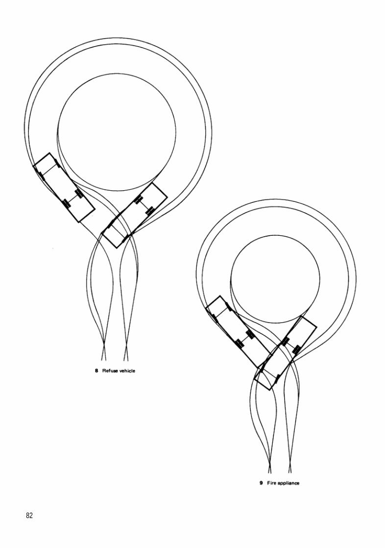
82

Full lock reverse
83

84

Hammerhead — T form
85

86

Hammerhead — Y form
87

88

Forward side turn
89

90

Reverse side turn
91

92

Passing places on narrowedcarriageways
1. To avoid opposing vehicles confronting each other on a narrowedstretch of carriageway they should be able to see each other before apassing bay is reached by the vehicle nearest to it.2. Thus in Figure 1 for vehicle B to pull into the bay it is necessary forthe driver to see vehicle A before B has reached point O. Point 0 isdependent on the speed of vehicle B and is the point beyond which Bcannot slow downorstop in time to enter thepassing bay. But, becauseeither vehicle A or B may be closest to the passing bay, both vehiclesmust be able to see each other before either has passed the point whereit cannot slow down or stop in time to use the bay.3. The implications of this are shown in Figure 2, illustrating that with asequence of passing bays the forward visibility distancesoverlap, eachbeing determined by the combined stopping distances of opposingvehicles plus the distance required between bays necessary to copewith the traffic volumes envisaged (see Appendix 4 in the first editionof this bulletin Studies of delays to traffic on single-lane carriagewayswith passing places76).
93

94
4. Where bends occur, thesame rules will apply as shown in Figure 3and itwill be appreciated that if passing bays were not provided on thebend the sight lines required between bays on each side of the bendcould sterilise a comparatively large amount of land. For similarreasons, itwill also normally be necessary to provide passing places atjunctions between narrowed carriageways (Figure 4) and at their entrypoint from carriageways of normal width (Figure 5).5. It should be emphasised that Figures 1-5 are purely diagrammatic.The shape and size of passing bays required will depend largely on thetypes and volumes of traffic to be coped with. Their location and designat junction points may also be affected by the need to allow vehicles toturn past others waiting in the passing bays. This again will beinfluenced by the volume of traffic but may also be influenced by thedirection of turn at the junction point (see Section 3).

Acknowledgements
Department of the Environment I Department of TransportWorking Party MembersB Aspin House Builders FederationK Clark Association of County CouncilsD Coates House Builders FederationD Davies (Chairman) House Performance Division, DOER Gercans Traffic Policy Division, DTpT Flanagan Association of Metropolitan AuthoritiesR Guinn National Joint Utilities GroupS Hacker Association of Metropolitan AuthoritiesC Lines Road Safety Division, TRRLJ Noble (Consultant)M Porter Planning Division PDC, DOEG Pye House Builders FederationM Selfe Association of County CouncilsP Shean National Joint Utilities GroupN Simon Planning Division PDC, DOEA Slack Association of District CouncilsA Smith (Secretary) Housing Management and Estate ActionDivision, DOEM Thorne Association of Metropolitan AuthoritiesP Tobia Planning Division PDC, DOER Watson Planning Division PDC, DOEE Wyatt Traffic Policy Division, DTpOther divisions within the DOE, DTp and TRRL contributed in writingto successive drafts of the bulletin.External consultationComments on a consultative draft of the bulletin were invited fromthe following:Government DepartmentsDepartment of the Environment, Northern IrelandDepartment of HealthHome OfficeScottish Development DepartmentWelsh OfficeOther bodiesAssociation of County CouncilsAssociation of District CouncilsAssociation of Metropolitan AuthoritiesAssociation of Municipal EngineersThe Atomic Energy AuthorityAutocycle UnionAutomobile AssociationThe Bicycle AssociationBritish Association of RemoversBus and Coach CouncilThe Centre for Accessible EnvironmentsCouncil for the Protection of Rural England
95

Cyclists Touring ClubDisabled Drivers’ AssociationFreight Transport AssociationFriends of the EarthHouse Builders FederationInstitute of Highway Incorporated EngineersInstitute of Road Safety OfficersThe Institution of Civil EngineersThe Institution of Highways and TransportationThe Landscape InstituteMetropolitan Planning Officers’ SocietyThe Motor Cycle Association of Great Britain LtdNational Dairymen’s AssociationNational House Building CouncilNational Joint Utilities GroupThe Pedestrians AssociationRoad Haulage AssociationRoad Operators’ Safety CouncilRoyal Automobile ClubRoyal Institute of British ArchitectsRoyal Institute of Chartered SurveyorsRoyal Society for the Prevention of AccidentsThe Royal Town Planning InstituteSafe Neighbour hoods Advisory ServiceSociety of Motor Manufacturers and Traders LtdTransport 2000 LimitedComments were received from various Local Planning and HighwayAuthorities both directly and through the Department’s RegionalOffices.
IndividualsThanks are due to the following individuals for their personalcomments:D Ball Borough of ThamesdownA Cribb Surrey County CouncilI Davison Birmingham PolytechnicDr M Jenks Oxford PolytechnicR Jones Surrey County CouncilI McChesney Lisney AssociatesA Newman Suffolk County CouncilT Pharoah South Bank PolytechnicN Sheppard Consultant ArchitectG Smith Oxford PolytechnicA Wise Birmingham City Engineer’s DepartmentLayout and typographyMike Chapman, DOE, in collaboration with Fred Stubbs, HMSO.
IllustrationsFirst edition: Ron WhitakerThis edition: Gill Siemak and Michelle Eden, DOE
PhotographsThanks for permission to reproduce copyright photographs are dueto the following:Birmingham City Engineer’s Department: Figure 140GLC’s Department of Architecture and Civic Design: Figures 74 and75John Noble: Figures 72, 73, 76, 77 and 78Norwich City Engineer’s Department: Figures 135, 136 and 139Wolverhampton Borough Council’s Environmental and TechnicalServices Department: Figures 137 and 138
96

References and Notes
1 Department of the Environment. Department of by public transport, or to provide access for peopleTransport. Design Bulletin 32 Residential roads with a mobility handicap.and footpaths: layout considerations. HMSO 1977011 750243x. 6 Department of the Environment. Circular 22/84
(WO 43/84). Memorandum on Structure and Local2 Department of Transport Local Authority Circular 1/Plans. HMSO 1984 011751 750x. See also:90 Transport Policies andProgrammeSubmissions
for 199 1/92 HMSO 1990 0115509046. This refers Planning Policy Guidance Note 12 Local Plans.HMSO 1988 011752168x.to government initiatives to reduce accidents and
includes provisions for local authorities to bid for Planning Policy Guidance Note 15 Regional Plan-transport supplementary grant within their TPP ningGuidance, Structure Plans, and the Content ofsubmissions for 1991/92 onwards for area wide Development Plans. HMSO 1990 0117523100.road safety measures. 7 BRE Digest 350 Climate andsite development. Part
3 The following relevant publications have been pro- 1: General climate of the UK. Part 2: Influence ofduced by the National Joint Utilities Group (c/o The microclimate. Part 3: Improving microclimateElectricity Council, London): through design. Building Research Establishment
1990.Publication No 2. Provision of mains and servicesby public utillties on residential estates. NJUG 8 BRE Digests 185 and 186 on traffic noise. Building1991. Research Establishment 1976.Publication No5. Model guidelines fortheplanning 9 DOE Circular 22/83. HMSO 1983 0117516988.and installation of utilities supplies to new building 10 Imaginatively designed roads and footpaths con-developments. NJUG May 1983. tribute to the success of many schemes that arePublication No 6. Services entries fornewdwellings given Housing Design Awards by the Departmenton residential estates. NJUG 1984. of the Environment, National House-Building Coun-
cil and Royal Institute of British Architects. AwardsPublication No 7. Recommendedpositions forutili-are given and details of schemes are publishedties’ mains and plant (services in new streets) forevery two years.new works. NJUG 1986.
11 Guidance and references on different aspects of4 Names for residential roads used in local design landscape design may be found in: Landscapeguides can be found in: design guide Volume 1 Soft Landscape. Volume 2
Noble (J). Localstandardsforthelayoutofresiden- Hard landscape PSA Projects. Authors - Adriantial roads: a review. Housing Research Foundation Lisney and Ken Fieldhouse. Editor - Jeremy Dodd.(c/o the National House-Building Council, London) Gower 1990. Vol 1 0566090171; Vol 20566090198.November 1983. See also Reference 56.
5 The following definitions are contained in the Insti- 12 Department of the Environment. Design Bulletin 27tution of Highways and Transportation publication Children at play. HMSO 1973 0117502367. SeeGuideilnes for Urban Safety Management. The also References 20, 21 and 22.Institution 1990 0902933078: 13 Goldsmith (5) Designing for the disabled. 3rd edi-‘Pedestrian routes’ - include footways, footpaths, tion. Royal Institute of British Architects 1976pedestrian streets, shared surfaces and shared 0900630507. See also:pedestrian and cyclist pathways. The Institution of Highways and Transportation‘Cycle routes’ - include separate cycle lanes, lightly Providing forpeople with a mobiiltyhandicap. 1986trafficked roads, and cycle tracks. (Under revision).‘Pedestrian streets’ - are primarily for the passage 14 Information on the planning and development ofof pedestrians, but may permit motor vehicles to cycle routes, creation of new cycle tracks, conver-enter at specified times for servicing, or for access
97

sion of footways or footpaths to cycle tracks, appro- 19 The Department of Transport Children and Roads:priate signing and cycle crossing facilities and can A Safer Way. The Department. May 1990. See also:be found in guidance published by the Department The Local AuthorityAssociations’ RoadSafetyCodeof Transport. The following general publications are of Good Practice. Association of County Councilsrelevant to the provision of cycling facilities: 1990.Town and Country Planning Act 1990. HMSO A Step Ahead-improvingthe pedestrian environ-0105408905. ment. Association of MetropolitanAuthorities 1989.Highways Act 1980. HMSO 0105466808.
20 Institution of Highway Engineers Effects of layoutCycle Tracks Act 1984. HMSO 0105438847. and design on residential road accidents by G
Bennett. The Institution.Cycle Tracks Regulations 1984. SI 1984 No. 1431.HMSO 0110474317. 21 Jenks (M). Residential roads researched. In The
Architects Journal. 29 June 1983.Traffic Advisory Leaflet 1/90 Cycling Bibliography.Department of Transport. 22 Noble (J), Bennett (G) and Jenks (M). Roads and
See also References 35,36 and 54. parking in private sectorhousing schemes: studiesofaccident records, innovative layouts andparking
15 Local Transport Note 1/91. Keep Buses Moving, provision. Housing Research Foundation (c/a theHMSO. National House-Building Council, London) May
1987.16 Transport Act 1985. HMSO 0105467855. It shouldbe borne mind that, under the Road Traffic Regula- 23 Noble (J) and Jenks (M). Safety and security intion Act 1984, highway authorities have general private sectorhousing schemes: a studyof layoutpowers to make Traffic Regulation Orders prohib- considerations. Housing Research Foundation (c/aiting, restricting or regulating the useof any particu- theNational House-Building Council, London) Sep-lar typesof traffic including public service vehicles. tember 1989.Also, under the Transport Act 1985 (Section 7)
24 The Institution of Highways and Transportation withthere are powers for a Traffic Commissioner toimpose Traffic Regulation Conditions (TRCs)on the the Department of Transport. Roads and traffic in
urban areas. HMSO 1987 011550818x. Generaloperation of local bus services at the request of ahighway authority to prevent danger to road users guidance on assessing environmental capacity is
given in Chapter 6.or to reduce severe traffic congestion. TRCs mayregulate the routes or stopping places used, when 25 The Government’s policies with regard to suchand for how long vehicles may stop, and reversing matters can be found in: This Common Inheritanceor turning manoeuvres. - Britain’s Environmental Strategy. HMSO 1990
0101120028.17 See Reference 2. The following publications pre-senting findings from the Urban Safety Project will 26 Department of the Environment Handbook of Es-also be relevant: tate Improvement. Part 1 Appraisingoptions. HMSO
1989 0117522325. Part 2 External areas and PartLynam (D.A), Mackie (A.M) and Davies (C.H).Urban Safety Project: 1. Design and implementa- 3 Dwelling are being prepared for publication. Part
2 will contain relevant guidance on security andtion of schemes. Department of Transport, TRAL crime prevention.Report RR1 53, Transport and Road Research Labo-ratory, Crowthorne 1988. 27 Warren (F) and Stollard (P). Safe as houses. Insti-
tute of Advanced Architectural Studies. UniversityMackie (A.M), Ward (H.A) and Walker(R.T). Urbanof York 1988 0904761185. See also:Safety Project: 2. Interim results for area-wide
schemes. Department of Transport, TRRL Report National House-Building Council. Guidance onhowRR154, Transport and Road Research Laboratory, the securityofnewhomes can be improved. NHBCCrowthorne 1988. London 1986.Mackie (A.M), Ward (H.A) and Walker (R.T). Urban Home Office. Practical ways to crack crime. HomeSafety Project: 3. Overall evaluation of area-wide Office 1988.schemes. Department of Transport, TRRL Report 28 Department of Transport. Circular Roads No. 4/90RR263, Transport and Road Research Laboratory, 20mph Speed Limit Zones. See also:Crowthorne 1990. Traffic Advisory Leaflet 7/91 20mph Speed Limit
18 Transport and Road Research Laboratory. Labora- Zones. Department of Transport Traffic Advisorytory Report LA 668. The Hampshire child pedes- Unit 1991.trian accidentstudy by G.R. Grayson. CrowthorneBerks. The Laboratory 1975. 29 See Reference 15.
30 Highways Act 1980. Sections 62, 75 and 77.
98

31 Bennett (G.T). Speeds in residential areas. In The 42 British Standards Institution. B.S. 5906: 1980: CodeHighway Engineer. 1983. Vol. 30. July No. 7. The of Practice forstorage andonsite treatment ofsolidabove article was based on findings reported in waste from buildings.Vehicle speedson residential roads. Departmentof 43 See References 15 and 24.the Environment. March 1982. (Unpublished).
44 See Reference 41.32 The Highways (Road Humps) Regulations 1990. SI1990No. 703. HMSO 0110037030. The regulations 45 See Reference 24. See also:allow round top and flat top humps to be kerb to Department of Transport. Department Standard TDkerb or tapered. Kerb to kerb humps would be 9/81 Road Layout and Geometry: Highway Linkneeded at pedestrian crossing places. See also: Design.
Circular Roads No. 3/90 RoadHumps. Department 46 Transport and Road Research Laboratory. TRRLof Transport. Working paperTSN 29R Studies ofdelays to trafficTraffic Advisory Leaflet 2/90 Speed Control Humps. on single-lane carriageways with passing placesDepartment of Transport. by I J Burrow. Crowthorne. Berks. The Laboratory
1977.The Traffic Signs (Amendment) Regulations andThe Traffic Signs (Amendment) General Directions 47 Transport and Road Research Laboratory. TRRL1990. SI 1990 No. 704. HMSO 0110037049. Supplementary Report 357 Attitudesofa sampleof
cyclists tousingsingle-trackroadsbyJ F Nicholson.33 Lynam (D.A.) Use and effectiveness of speed re- Crowthorne. Berks. The Laboratory 1978.ducing measures in urban areas. Road Safety
Division. Transport and Road Research Laboratory 48 British Standards Institution. BS 5588: Fire Precau-1987 (Unpublished). tions in the design, construction and use of build-
ings. Part 1: 1990 Code of practice for residential34 Sumner(R)and Baguley(C). Speed control humps buildings. Also, a proposed building regulation
on residential roads. TRRL Report 878. Transport dealing with this subject is being prepared. Theand Road Research Laboratory, Crowthorne 1979. latest draft rounds up the minimum width of car-See also: riageway from 3.66m to 3.7m.Watts (G.R). Roadhumps for the control of vehicle 49 Departmentof Transport. Department StandardTDspeeds. TRRL Report 597. Transport and Road 16/84 The Geometric Design of Roundabouts.Research Laboratory, Crowthorne 1973.
50 Department of Transport. Departmental Advice Note35 See Reference 21.TA 42/84 The Geometric Design of Roundabouts.
36 See Reference 33. See also:37 Department of Transport. TrafficAdvisory Unit Leaf- Department of Transport. TA 23/81. Junctions and
let 1/87 Measures to control traffic for the benefit of Accesses: determination of size of roundaboutsresidents, pedestrians and cyclists. The Depart- and major/minorjunctions.ment 1987.
51 Department ofTransport. Departmental Advice Note38 DepartmentoTransport,Welsh Office. Local Trans- TA 20/84 Junctions and Accesses: the layout of
port Note 1986/2. Shared use by cyclists and major/minor junctions.pedestrians. HMSO 0115507833. 52 Department of the Environment. Planning Policy
39 See Reference 3. Guidance PPG 13. Highways considerations in
40 British Standards Institution. BS 5489: Road Light- development control. HMSO November 19880117521558.ing: Part 1: 1987 Guide to the general principles.
Part 3: 1989 Code of Practice for lighting for 53 DepartmentofTransport. DepartmentalAdvice Notesubsidiary roads and associatedpedestrian areas. TA 22/81 Vehicle speedmeasurements on all pur-Part 9: 1990Code ofpractice for lighting for urban pose roads.centres and public amenity areas. 54 See Reference 52.
41 Home Office. Fire Department Fire Prevention Note 55 Department of Transport Disability Unit Circular1/70 Access for fire appliances. Home Office 1970. DU 1/86.Local fireservicesshould always be consulted. Seealso: 56 Department of Transport. Departmental Standard
TD/2/78 Pedestrian Subways: Layout and Dimen-British Standards Institution. BS 5588: Fire Precau- sions.tions in the design, construction and use of build-ings. Part 1: 1990 Code of practice for residentialbuildings.
99

57 Guidance on requirements and provision for cy- 64 See Reference 17.clists can be found in: 65 See Reference 24.DepartrnentofTransport, Welsh Off ice. Local Trans- 66 See Reference 26.port Note 1989/1. Making way for cyclists. HMSO0115509089. 67 Department of Transport. Manual ofenvironmental
appraisal. DTp 1983 (Out of print at present).Departmentof Transport, Welsh Office. Local Trans-port Note 1986/2. Shared use by cyclists and 68 Other publications that may be relevant include:pedestrians. HMSO 0115507833. ALBES Highways and traffic management in Lon-DepartmentofTransport, Welsh Office. Local Trans- don. HMSO 1986 0115507124.port Note 1986/1. Cyclists at road crossings and LAA Road Safety Code of Good Practice (seejunctions. HMSO 0115507825. Reference 18).
DepartmentofTransport, Welsh Office. LocalTrans- Civic Trust, Department of Transport and Countyport Note 1987/2. Signs for cycle facilities. HMSO Surveyors Society. Lorries and Traffic Manage-0115508341.
ment.Traffic Advisory Leaflet 4/90. Tactile Markings for Local Authority Associations’HighwayMaintenance:Segregated Shared Use by Cyclists and Pedestri- A Code of Good Practice.ans. Department of Transport Traffic Advisory Unit1990. Joint LAAs/DTp report on AlP (Accident Investiga-
tion and Prevention) schemes.DepartmentofTransport. Departmental Advice NoteTA 57/87. Roadside Features. 69 DepartmentofTransport. TrafficAdvisory Unit Leaf-
let 1/87. Measures to control traffic forthe benefit ofStatutory Instrument 1981 No 859. The Traffic Signs residents, pedestrians and cyclists. The Depart-Regulations and General Directions. HMSO 1981 ment 1987.0110168593.
70 See Reference 32.Statutory Instrument 1982 No 1879. The TrafficSigns (Amendment) Regulations. HMSO 1983 71 See Reference 5.0110278798.
72 See Reference 57.Statutory Instrument 1982 No 1880. The Traffic 73 See References 14, 37, 38 and 57.Signs (Amendment) Regulations. HMSO 19830110278801. 74 Road Traffic Regulation Act 1984. HMSO
0105427845.WBM and NP series working drawings for signsrequiring authorisationby the Departmentof Trans- 75 Transport and Road Research Laboratory. Labora-port are available from TP/SSL Division, Depart- tory Report LR 608 Road width requirements ofment of Transport, St Christopher House, South- commercial vehicles when cornering by G Brock.wark Street, London SE1. Crowthorne Berks. The Laboratory 1973.
58 La Dell (T), Parker (I) and Cole (R). Shrub planting 76 See Reference 46.on housing estate roads. In Landscape Design,May 1982.
59 Guidance on this subject for house-builders hasbeen published in Landscapes for New Housing:The Builders Manual by Professor Chris Baines forthe New Homes Marketing Board, London. May1990.
60 Highways Act 1980.
61 Joint publication by the ACC, AMA, ADC and HBF.Roads for Adoption. A Model Section 38 Agree-ment (Highways Act 1980). Second Edition, March1990.
62 Reference 22 contains-information on the implica-tions of developing local parking standards to takethese considerations into account.
63 See References 26 and 28, the forthcoming DOEcircularon renewal areas, and Departmentof Trans-port Circular Roads No. 4/9020mph zones.
100

Index
A
Access: 9-12cyclists: 10drivers: 10-11for emergency services: 11, 21-22,36,41for service vehicles: 22pedestrians: 10public transport: 11-12, 23roads, definition: 2to dwellings: 20-23
Accidents: 12-13, 70see also safetyaccident risk perception: 71child pedestrians: 12
Adoption agreements: 65Ambulances: 17
access: 11Area improvement policies: 69
B
Barriers: 56, 73Bends: 4142
carriageway widths: 4142layout: 37visibility: 37, 53-54
Blind peopletactile surfaces: 57-56
British Standards InstitutionBritish Standard 5489 parts 1,3 and9:33British Standard 5588 part 1: 41
Building densities: 6Bus shelters
footway widths: 56Bus stops: 71
design: 23Buses: 17
access: 11,23routes: 71school buses: 11service provision: 11-1 2turning characteristics: 39
C
Caravans: 62
Carriageways: 39-41,43, 54,93definition: 2emergency access: 41gradients: 4344layout: 37narrowed carriageways: 4041, 93passing places: 73tolerances: 3940widths and alignment: 34, 3941
Cars: 34turning characteristics: 71
Children: 12at play: 6, 10safety barriers: 56
Children and roads: a safer way: 12Common trench: 32Conservation areas: 64Crime: 14-15, 71
footpath layout: 29prevention measures: 64security: 14-15
Cross roads: 44staggered: 45
Culs-de-sac roads: 73accident record: 13security enhancement: 21
Cycle tracks: 56, 75-76definition: 2headroom: 56layout: 29provision: 10segregated: 58,75visibility: 56
Cycle Tracks Act 1984: 76Cyclists: 29, 56, 75-76
access: 10carriageway widths: 4041provision in improvement schemes:75safety: 4041segregation: 75
D
Department of the EnvironmentHandbook of Estate Improvement71
Department of TransportDepartmental Advice Note 42/84:45Departmental Advice Note TA 22/81: 52Departmental Standard TD 16/84:45Manual of Environmental Appraisal:71
Design brief: 3-16aims: 3planning guidance: 5
Design guidance: 63local guides: 64
Developers: 64Development plans: 5, 64
local plans: 5structure plans: 5Unitary Development Plans: 5
Direction finding: 26Disabled people
design: 10footpath gradients: 57parking arrangements: 35, 60
Distributor roads: 14, 17, 39, 46junction spacing: 45
Drivers: 39access: 10-11visibility: 50
Driveways: 49, 59-60design: 34, 59-60shared: 2,29,33,59underground services: 33
Dust cartssee refuse collection vehicles
E
Elderly people: 10Emergency services: 17, 21-22Energy conservation: 6, 13-14Estate management
security: 14
F
Fire appliances: 41, 62turning characteristics: 79
Fire Prevention Note 1/70: 39
101

Fire service: 17, 38, 39, 41, 57Footbridges
headroom: 82Footpaths: 18, 57-58
barriers: 58cyclist provision: 29definition: 2design: 3, 8-9headroom: 57kerbs: 57layout: 29,37ramp gradients: 57widths: 57
Footways: 77definition: 2headroom: 58layout: 37widths:56
Furniture removal vans: 34see also pantechnicons
G
Garages: 34, 88grouped garage forecourts: 81, 87
Gradients: 18, 4344cycle tracks: 58footpaths: 57
H
Hardstandings: 34, 88Hierarchies
residential roads: 15, 71traffic distribution: 15
Highway authorities: 33,40,64-65Highways Act 1980:24,76
s.38: 85Advanced Payments Code: 85
Highways (Road Hump) Regulations1990 25,74House numbers: 28
I
IHT guidelines on Urban SafetyManagement: 75Improvement schemes: 89-77
costs: 72cyclist provision: 75design concept: 70,72layout characteristics: 71parking: 78pedestrian provision: 75speed restraints: 73-74vehicle flows: 72vehicle speeds: 73
Intervisibilitysee visibility
J
Junctions: 37,44,746-47radii: 4848raised junctions, vehicle speedcontrol: 28safety planning: 12, 28, 47spacing: 45T-junctions: 45visibility: 37Y-junctions: 45
K
Kerbs: 47, 49, 57-58radii: 48
L
Landscaping: 7characteristks: 5maintenance: 7tree planting: 8
Layout design: 17-62characteristics: 71through routes: 19
Lighting: 27-28, 33design: 33-34
Local authorities: 84improvement schemes: 89
Local design guidance: 83-84parking provision: 65-67
Local guides: 84Local plans: 5Local Transport Note 2/86 75Local Transport Note 1/91: 39
M
Milk floats: 17, 44, 47Motor caravans: 82
N
Noise: 8, 13, 70noise barriers: 8
0
One-way streets: 19,72Open space: 15,32
security: 32
P
Pantechnicons: 42,49turning characteristics: 79
Parking: 34-38, 38, 59, 85, 78-77allocation:36,66barriers: 57communal parking areas: 60-62
control: 38disabled people: 35driveways: 59-60grouped parking areas: 56,60-61improvement schemes: 76-77location: 34,66off-street provision: 7, 18, 34-35,85on-street provision: 7, 18, 34-35,38,40,66parking standards preparation: 85provision: 34-35, 50, 65-67, 78residents’ cars: 34,59service vehicles: 34short term: 18visitors’ cars: 34
Parking baysdimensions: 60-61layout demarcation: 82
Passing bays: 93Paving materials: 82Pedestrians
access: 10children: 12,50, 58crossing points at junctions: 47provision for pedestrians: 29, 75safety barriers: 58
Planning authorities: 5, 84Planning guidance: 5Planning Policy Guidance PPG 13:52Play areas: 10, 32Pollution
air: 13, 70noise: 13, 70
Prams: 58-57Priority markings: 45Public transport
see also busesaccess: 11;12
R
Ramps: 57Refuse collection vehicles: 17, 38,44,47,49
turning characteristics: 79Residential roads: 46,49
definition: 2design: 3, 8-9, 83hierarchical network arrangement:15,71transitional roads: 20
Road charges: 85Road Traffic Regulation Act 1984: 98Roads and Traffic in Urban Areas:39,45,71Roundabouts
mini: 45
102

S
Safety: 32see also accidentsroad design: 12, 21shared surface roads: 13,29tactile surfaces: 58
Service vehicles: 22,34, 57parking: 34,62
Shared surface roads: 9,29-30definition: 2design: 13, 29-30gradients: 44safety: 13,75visual characteristics: 31
Shrubs and hedges: 5-6, 9, 27, 32,59
planting: 7, 21, 32, 51selection: 59, 64
Signposting: 26Site layout: 5Speed limits: 23, 27, 53
20 mph zones: 12,16,69,74grouped parking areas: 56
Speed restraints: 24-26, 73alignment changes: 24-27chicanes: 25,73improvement schemes: 73islands: 25, 73mountable shoulders: 25,42,49raised junctions: 26, 73road humps: 26,73-74speed tables: 26, 73-74
Statutory services: 32access: 32preferred routes: 33shared driveways: 33
Stopping distances: 50-51, 53Street cleaning: 49Street lighting
see lightingStreet names: 17,28Structure plans: 5Subways: 57
T
Tactile surfaces: 57-58Taxis: 17
access: 11,22Telephone kiosks: 18Through routes: 19Traffic authorities: 76Traffic distribution: 15-l 6
hierarchical network arrangement:15-16, 71
Traffic flows: 13, 16, 44-45, 72-73Traffic nuisance: 13, 17
Transport and Road ResearchLaboratory
Report 608 75 Appendix 1: 79Urban Safety Projects reports: 71
Trees: 7, 27, 47, 59planting: 5-6, 21, 51selection: 9, 32, 59, 64
Turning bays: 73Turning characteristics: 79Turning spaces: 29,49-50
layout: 37location: 49-50
U
Underground services: 18, 32, 41, 57see a/so statutory undertakerspreferred routes: 33
Unitary Development Plans: 5Urban road network
definition: 2
V
Vandalism: 14, 71Vehicle flows: 17, 19-20
improvement schemes: 72Vehicle speeds: 23-28
improvement schemes: 73Vehicles: 39, 42
access: 41geometric characteristics: 39movement patterns: 16, 47speed restraint: 16-l 7stopping distances: 50-51tolerances: 39turning characteristics: 49, 79volume: 16
Verges: 9, 18, 32, 41planting: 32, 59use by underground services: 33,38, 41widths: 58
Vibration: 70Visibility: 17, 23, 50-56, 93
at junctions: 36-37, 51-53at summits: 37, 50carriageway edges: 54distances: 23, 50, 52, 93heights: 50-51on bends: 37,42,53-54,93parking areas: 34,56radii: 53standards: 52-53
W
Wheelchairs and wheelchair users:10,35,50,57,60
Printed in the United Kingdom for HMSODd0301948 1/96 c 5 3400/4 3 4 3 0 8 5 02/34416
103