design optimization and verification of a horizontal ... · in addition, the low airfoil of the...
TRANSCRIPT
Design Optimization and Verification of a Horizontal Stabilizer for the SeaStryder600 Wing-
In-Ground-Effect (WIG) Aircraft
by
Stephen Haley
A thesis submitted in conformity with the requirements for the degree of Master of Applied Science
Graduate Department of Mechanical and Industrial Engineering University of Toronto
© Copyright by Stephen Haley 2012
ii
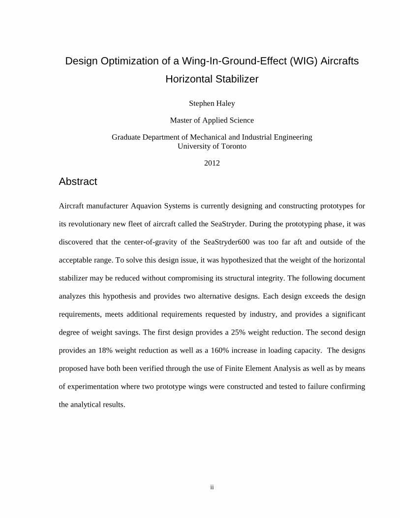
Design Optimization of a Wing-In-Ground-Effect (WIG) Aircrafts
Horizontal Stabilizer
Stephen Haley
Master of Applied Science
Graduate Department of Mechanical and Industrial Engineering
University of Toronto
2012
Abstract
Aircraft manufacturer Aquavion Systems is currently designing and constructing prototypes for
its revolutionary new fleet of aircraft called the SeaStryder. During the prototyping phase, it was
discovered that the center-of-gravity of the SeaStryder600 was too far aft and outside of the
acceptable range. To solve this design issue, it was hypothesized that the weight of the horizontal
stabilizer may be reduced without compromising its structural integrity. The following document
analyzes this hypothesis and provides two alternative designs. Each design exceeds the design
requirements, meets additional requirements requested by industry, and provides a significant
degree of weight savings. The first design provides a 25% weight reduction. The second design
provides an 18% weight reduction as well as a 160% increase in loading capacity. The designs
proposed have both been verified through the use of Finite Element Analysis as well as by means
of experimentation where two prototype wings were constructed and tested to failure confirming
the analytical results.

iii
Acknowledgments
I would like to express my sincere gratitude towards the University of Toronto for providing me
with the opportunity to study at one of the most prestigious schools in the country. The following
research would not have been possible without the equipment, working facilities, and financial
support that was provided, and I am sincerely appreciative of this. Particularly, I would like to
thank my academic supervisor, Professor Cleghorn, for the guidance and support. The countless
hours spent reviewing and editing my research was greatly beneficial. Lastly, I would like to
thank my industry supervisor, Ray Richards, for providing the industry project with Aquavion
Systems Corp. The project was a pleasure to work on and taught me many invaluable skills,
particularly relating to the application and analysis of composite materials.

iv
Table of Contents
Table of Contents
Acknowledgments .......................................................................................................................... iii
Table of Contents ........................................................................................................................... iv
List of Tables ................................................................................................................................ vii
List of Figures .............................................................................................................................. viii
List of Appendices ........................................................................................................................ xii
1 Introduction ................................................................................................................................ 1
1.1 The SeaStryder .................................................................................................................... 1
1.2 Motivation ........................................................................................................................... 4
1.3 Objectives ........................................................................................................................... 4
1.4 Introduction to Wings and the Theory of Flight ................................................................. 5
1.4.1 Airfoil Definitions and Terminology ...................................................................... 5
1.4.2 Overview of aerodynamics ..................................................................................... 8
1.4.3 Boundary Layer Concept ...................................................................................... 11
1.4.4 Considerations for Finite Wings ........................................................................... 12
1.4.5 Planform Considerations: ...................................................................................... 13
1.4.6 Wing-in-Ground-Effect Aircraft ........................................................................... 14
2 Background Research ............................................................................................................... 15
2.1 Current Industry Design of Horizontal Stabilizer ............................................................. 15
2.1.1 Physical Configuration .......................................................................................... 15
2.1.2 Specifications Provided by Industry ..................................................................... 16
2.1.3 Current Design Issues ........................................................................................... 17
2.2 Future Design Considerations ........................................................................................... 18

v
2.2.1 Design Requirements ............................................................................................ 18
2.2.2 State-of-art ............................................................................................................ 20
3 Materials and Methods ............................................................................................................. 24
3.1 Design Concept ................................................................................................................. 24
3.1.1 Design Overview .................................................................................................. 24
3.1.2 Servo Housing and Elevator Control .................................................................... 25
3.1.3 Base Support Design ............................................................................................. 27
3.1.4 Composite Sandwich Structure ............................................................................. 28
3.1.5 Accelerometers ..................................................................................................... 29
3.2 Materials and Apparatus ................................................................................................... 29
3.2.1 Apparatus .............................................................................................................. 29
3.2.2 Materials Used ...................................................................................................... 30
3.3 Preliminary Experimentation ............................................................................................ 31
3.3.1 Base Support Experiment ..................................................................................... 31
3.3.2 Composite Sandwich Panel Experiment ............................................................... 35
3.4 Design Validation and Experimentation ........................................................................... 39
4 Results and Discussion ............................................................................................................. 44
4.1 Base Support Experiment ................................................................................................. 44
4.2 Composite Sandwich Panel Experiment ........................................................................... 45
4.2.1 Beam 1 .................................................................................................................. 45
4.2.2 Beam 2 .................................................................................................................. 46
4.2.3 Beam 3 .................................................................................................................. 47
4.2.4 Beam 4 .................................................................................................................. 49
4.2.5 Beam 5 .................................................................................................................. 50
4.3 Design Validation and Experimentation ........................................................................... 52
4.3.1 Wing 1 ................................................................................................................... 53
vi
4.3.2 Wing 2 ................................................................................................................... 54
5 Conclusions and Recommendations ........................................................................................ 56
5.1 Base Support Experiment ................................................................................................. 56
5.2 Composite Sandwich Panel Experiment ........................................................................... 56
5.3 Design Validation and Experimentation ........................................................................... 57
5.4 Scientific contributions ..................................................................................................... 58
5.5 Future Recommendations ................................................................................................. 58
Bibliography ................................................................................................................................. 59
vii
List of Tables
Table 1: Composite Sandwich Panel Structures ........................................................................... 29
Table 2: 4 Bar Linkage Specifications .......................................................................................... 90
Table 3: Beam Study Results ...................................................................................................... 101
Table 4: Wing Study Results ...................................................................................................... 104
Table 5: Deflection-Load Results ............................................................................................... 105

viii
List of Figures
Figure 1: Quarter Scale SeaStryder600 Hydroplaning ................................................................... 1
Figure 2: Double Dihedral Wing Configuration ............................................................................. 2
Figure 3: SeaStryder600 ................................................................................................................. 3
Figure 4: Airfoil Nomenclature ...................................................................................................... 6
Figure 5: Wing Sweep .................................................................................................................... 6
Figure 6: Control Surfaces .............................................................................................................. 7
Figure 7: Rib and Spar Configuration ............................................................................................. 7
Figure 8: Cartesian coordinate system used in the study of aerodynamics .................................... 8
Figure 9: Section Forces and Moments .......................................................................................... 9
Figure 10: Boundary Layer Flow over a Streamlined Body at a low angle of attack ................... 11
Figure 11: Example of Boundary Layer Separation ..................................................................... 11
Figure 12: Example of Wingtip Vortices ...................................................................................... 12
Figure 13: Airfoil Downwash ....................................................................................................... 13
Figure 14: Current Industry Design of the Quarter Scale Horizontal Stabilizer ........................... 15
Figure 15: Industry Testing of Support Spar ................................................................................ 16
Figure 16: Stryder600 Side View ................................................................................................. 17
Figure 17: Close up of Industry Design Showing Servo Assembly ............................................. 17
Figure 18: Servo Assembly Cover Plate ....................................................................................... 18
Figure 19: Configuration of R. Warsi Sullivans Design ............................................................... 21
ix
Figure 20: Failure of Design ......................................................................................................... 22
Figure 21: Z-pin reinforcement proposed by D. U. Long ............................................................. 23
Figure 22: Elevator Control Mechanism Model ........................................................................... 26
Figure 23: Elevator Control Mechanism Model Cross-Section .................................................... 26
Figure 24: Base Structure Model .................................................................................................. 27
Figure 25: Simple Base Structure Design ..................................................................................... 28
Figure 26: Base Structure with added Support Walls ................................................................... 28
Figure 27: Construction of First Support Base ............................................................................. 32
Figure 28: Construction of Second Support Base ......................................................................... 33
Figure 29: Addition of composite Sandwich Panel ...................................................................... 33
Figure 30: Base 1 - Unloaded ....................................................................................................... 34
Figure 31: Base 1 - Fully Loaded Prior to Failure ........................................................................ 34
Figure 32: Base 2 - Unloaded ....................................................................................................... 34
Figure 33: Base 2 - Fully Loaded Prior to Beam Failure .............................................................. 35
Figure 34: Composition of Beam 1 ............................................................................................... 35
Figure 35: Composition of Beam 2 ............................................................................................... 36
Figure 36: Composition of Beam 3 ............................................................................................... 36
Figure 37: Composition of Beam 4 ............................................................................................... 36
Figure 38: Composition of Beam 5 ............................................................................................... 37
Figure 39: Experimental Set-Up for Testing Elasticity ................................................................ 38

x
Figure 40: Vertical Stabilizer Initial Core Templates ................................................................... 39
Figure 41: Finishing the Vertical Stabilizer Core ......................................................................... 40
Figure 42: Finalizing the Vertical Stabilizer Replica ................................................................... 40
Figure 43: Wing Base Support ...................................................................................................... 41
Figure 44: Completing the Base Support ...................................................................................... 41
Figure 45: Completing the Wing .................................................................................................. 42
Figure 46: Divinycell Hotwire Cutting Failure ............................................................................. 43
Figure 47: Base Failure ................................................................................................................. 44
Figure 48: CAD Analysis of Beam 1 ............................................................................................ 46
Figure 49: Failure of Beam 2 ........................................................................................................ 46
Figure 50: CAD Analysis of Beam 2 ............................................................................................ 47
Figure 51: Beam 2 - Unloaded (Top) and Fully Loaded (Bottom) ............................................... 47
Figure 52: CAD Analysis of Beam 3 ............................................................................................ 48
Figure 53: Upper Surface Failure of beam 4 in Tension .............................................................. 49
Figure 54: CAD Analysis of Beam 4 ............................................................................................ 50
Figure 55: Delamination Failure of Beam 5 ................................................................................ 51
Figure 56: CAD Analysis of Beam 5 ............................................................................................ 52
Figure 57: Beam 5 - Unloaded (a) and Fully Loaded (b) ............................................................. 52
Figure 58: CAD Analysis of Wing 1 ............................................................................................ 54
Figure 59: CAD Analysis of Wing 2 ............................................................................................ 55
xi
Figure 60: Graphical Results of Beam Experiment ...................................................................... 56
Figure 61: 4 Bar Linkage Schematic ............................................................................................ 90
Figure 62: DS8711 Servo Torque (24.99 kg-cm)/Hinge Moment Characteristics ....................... 91
Figure 63: Beam 1 Loading Positions ........................................................................................... 92
Figure 64: Beams 2-5 Loading Positions ..................................................................................... 92
Figure 65: Wing Loading Positions ............................................................................................. 93
Figure 66: Accelerometer Input Vibration Example .................................................................... 94
Figure 67: Output after Separation of Bending and Torsional Vibration ..................................... 94
Figure 68: Beam 1 Cross-Section ................................................................................................. 95
Figure 69: Beam 2 Cross-Section ................................................................................................. 96
Figure 70: Beam 3 Cross-Section ................................................................................................. 97
Figure 71: Beam 4 Cross-Section ................................................................................................. 99
Figure 72: Beam 3 Cross-Section ............................................................................................... 100
Figure 73: Deflection-Load Curve .............................................................................................. 105
Figure 74: CAD Deflection Study .............................................................................................. 105
Figure 75: Geometric Limit of Deflection ( 10 for illustrative purposes) ................................ 109
Figure 76: True Geometric Limit of Deflection ......................................................................... 109
xii
List of Appendices
Appendix I – Design Details and Documentation ........................................................................ 61
Appendix II – NACA 0009/0012 Profiles .................................................................................... 89
Appendix III – Hinge Moment Calculations and Characteristics ................................................. 90
Appendix IV – Beam Loading Positions ...................................................................................... 92
Appendix V – Example of Accelerometer Input / Output ............................................................ 94
Appendix VI – Experimental Results: Beam Bending Study ....................................................... 95
Appendix VII – Experimental Results: Wing Study ................................................................... 102
Appendix VIII –Experimental Results: Stiffness Test ................................................................ 105
Appendix IX – Material Data Sheets .......................................................................................... 106
Appendix X – Evaluation of Design Requirements .................................................................... 109
1
Chapter 1 Introduction
1 Introduction
1.1 The SeaStryder
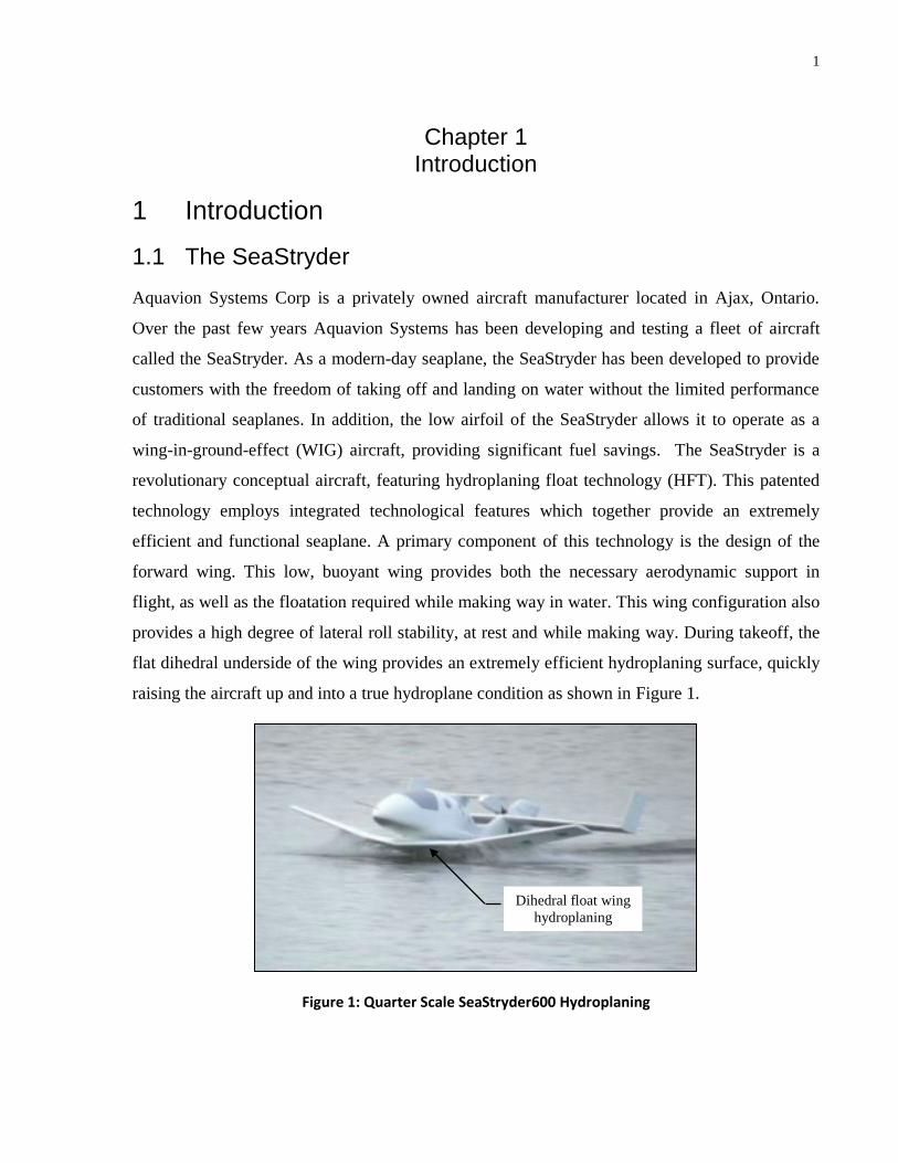
Aquavion Systems Corp is a privately owned aircraft manufacturer located in Ajax, Ontario.
Over the past few years Aquavion Systems has been developing and testing a fleet of aircraft
called the SeaStryder. As a modern-day seaplane, the SeaStryder has been developed to provide
customers with the freedom of taking off and landing on water without the limited performance
of traditional seaplanes. In addition, the low airfoil of the SeaStryder allows it to operate as a
wing-in-ground-effect (WIG) aircraft, providing significant fuel savings. The SeaStryder is a
revolutionary conceptual aircraft, featuring hydroplaning float technology (HFT). This patented
technology employs integrated technological features which together provide an extremely
efficient and functional seaplane. A primary component of this technology is the design of the
forward wing. This low, buoyant wing provides both the necessary aerodynamic support in
flight, as well as the floatation required while making way in water. This wing configuration also
provides a high degree of lateral roll stability, at rest and while making way. During takeoff, the
flat dihedral underside of the wing provides an extremely efficient hydroplaning surface, quickly
raising the aircraft up and into a true hydroplane condition as shown in Figure 1.
Figure 1: Quarter Scale SeaStryder600 Hydroplaning
Dihedral float wing
hydroplaning
2
Once hydroplaning, takeoff is possible in only a matter of seconds, which is remarkable in
comparison to traditional seaplane designs. While very low hydroplaning speeds are possible, at
higher speeds the trailing edge of the main wing, near the root section, serves as a high speed
hydroplaning surface which allows for increase aircraft mobility and breaks the water surface
suction to allow for a smooth liftoff. This integration of functions is the basis of Hydroplaning
Float Technology (HFT). Traditional seaplanes require the use of sponsons and often additional
floats to provide the necessary lateral roll stability. These features, while necessary on the water,
inherently produce significant drag when airborne. This results in increased fuel consumption
and inferior performance. HFT eliminates all of this by allowing the wing to serve many
functions without compromising performance.
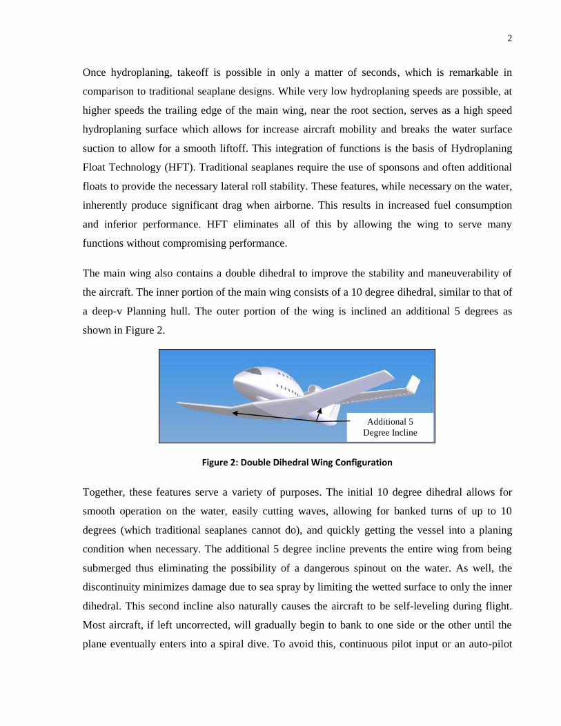
The main wing also contains a double dihedral to improve the stability and maneuverability of
the aircraft. The inner portion of the main wing consists of a 10 degree dihedral, similar to that of
a deep-v Planning hull. The outer portion of the wing is inclined an additional 5 degrees as
shown in Figure 2.
Figure 2: Double Dihedral Wing Configuration
Together, these features serve a variety of purposes. The initial 10 degree dihedral allows for
smooth operation on the water, easily cutting waves, allowing for banked turns of up to 10
degrees (which traditional seaplanes cannot do), and quickly getting the vessel into a planing
condition when necessary. The additional 5 degree incline prevents the entire wing from being
submerged thus eliminating the possibility of a dangerous spinout on the water. As well, the
discontinuity minimizes damage due to sea spray by limiting the wetted surface to only the inner
dihedral. This second incline also naturally causes the aircraft to be self-leveling during flight.
Most aircraft, if left uncorrected, will gradually begin to bank to one side or the other until the
plane eventually enters into a spiral dive. To avoid this, continuous pilot input or an auto-pilot
Additional 5
Degree Incline

3
system is necessary. The double dihedral configuration inherently maintains level flight and even
after a banked turn, will automatically return the aircraft into a balanced level position.
The design of the horizontal stabilizers (or rear wings) also play a vital role in the HFT.
Traditional aircraft generally maintain a slight downward pitching moment about the main wing.
This leaves the horizontal stabilizers responsible for providing a slight down-lift to compensate
and keep the aircraft balanced. The SeaStryder operates in a tandem wing configuration whereby
both the main wing and the horizontal stabilizers provide significant uplift. This is due to the fact
that the aircraft must maintain a more aft-ward center of gravity to allow for smooth
hydroplaning when navigating as a seagoing vessel. The tandem wing configuration provides the
additional advantage of an increase ranged and endurance as there is no longer a need to
maintain the balancing moment known as trim-drag.
The SeaStryder series has a broad potential market ranging from general aviation to commercial
uses such as passenger and cargo transportation, military use and UAV (Unmanned Aerial
Vehicle) applications. The SeaStryder is also particularly well suited for high-speed ground
effect transportation. Any aircraft with a low lying primary wing such as the SeaStryder is highly
susceptible to experiencing the advantageous effects of ground effect when flying within one
wing-span of the ground. At this low altitude the air beneath the wing acts as a cushion beneath
the wing and dramatically increases the fuel efficiency though a “cushioning” effect. This
phenomenon is discussed in more detail in Section 1.4.6, Wing-in-Ground-Effect Aircraft.
The SeaStryder600 shown in Figure 3 is one of three varying configurations of the SeaStryder.
Figure 3: SeaStryder600
The smallest of the SeaStryder line up is the SeaStryder200, a two passenger, 773 [kg] aircraft
with a cabin width of 1.2 [m]. This is followed by the SeaStryder600, a 4 passenger, 2273 [kg]
aircraft with a cabin width of 2.0 [m]and standing headroom. Lastly, is the much larger
4
SeaStryder6000, a 100 passenger commercial aircraft capable of supporting a 4560 [kg] payload.
The SeaStryder600 is the design of interest in this research. A quarter scale prototype of the
aircraft has been constructed for analysis and preliminary flight testing. The following are the
specifications for the full scale SeaStryder600 aircraft proposed by Aquavion Systems:
Amphibious operation
Sleeps 4 people (2 fore & 2 aft)
Stand-up headroom (72 inches)
80-inch cabin width
Lav/Shower/Galley facilities
Door & Canopy entry
Hydroplaning floatwing for lowest drag in flight
Walkway or on-water swim access to engine/props
Fly-by-wire control operation
Glass cockpit
Fully composite airframe
Tricycle gear, water thrusters
5000 lb (2273 kg) maximum weight
Range: 1300 nm
Max: 228 mph (198 kts)
Cruise: 200 mph (174 kts)
59 mph (51 kts) stall with flaps
Single 600 hp turboprop or twin 300 hp piston engines
1.2 Motivation
Industry testing of the scale prototype model of the SeaStryder600 has revealed the need to
reduce weight in the tail end, specifically in the horizontal stabilizer fins. The following research
is premised on the belief that greater weight reduction is achievable by incorporating modern
design methods and materials. This must be done while maintaining the structural rigidity and
damping to avoid aeroelastic flutter.
1.3 Objectives
The primary objectives of the research are to design and verify a new horizontal stabilizer with
reduced weight, and acceptable strength and stiffness characteristics. The scope includes
identifying optimal characteristics of key design features and components, specifically, material
choices, panel thicknesses, internal geometry, and eventually the resulting analytically defined
properties and fabrication method.
5
1.4 Introduction to Wings and the Theory of Flight
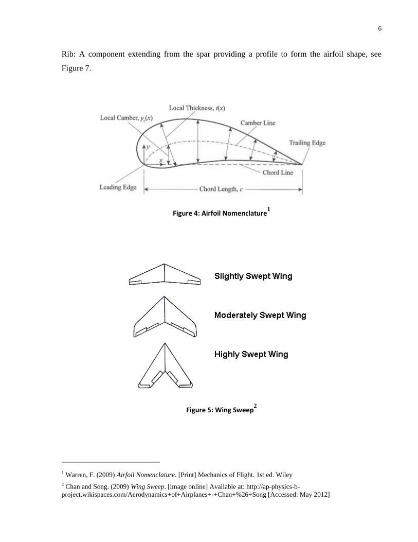
1.4.1 Airfoil Definitions and Terminology
The following terms are used throughout the document and should be understood:
Leading Edge: The forward edge of a wing, see Figure 4.
Trailing Edge: The aft edge of a wing, see Figure 4.
Chord Length: Distance from the leading edge to the trailing edge, see Figure 4.
Wingspan: The distance measured from one wingtip to the opposing wingtip.
Aspect ratio: Ratio of wingspan to chord length.
Camber line: The line midway between the upper and lower surfaces of an airfoil section as
measured perpendicular to the camber line itself, see Figure 4.
Downwash: The downward velocity component of air flowing off the trailing edge.
Planform: The shape and layout of a fixed-wing aircraft's fuselage and wing structure.
Sweep: Angle between the wingspan and centerline of aircraft (0° sweep would be perpendicular
wings), see Figure 5.
Port/Starboard: Starboard (Stbd) refers to the right hand side of the aircraft when facing forward,
Port refers to the left.
Control Surface: A movable surface used to direct the flow of air off the aircraft, thus providing
a means of aircraft control, see Figure 6.
Aileron: A control surface mounted on the trailing edge of the main wing of an aircraft, see
Figure 6.
Elevator: A control surface mounted on the trailing edge of the horizontal stabilizer, see Figure
6.
Spar: Main wing support structure generally extending the length of the wingspan, see Figure 7.
6
Rib: A component extending from the spar providing a profile to form the airfoil shape, see
Figure 7.
Figure 4: Airfoil Nomenclature1
Figure 5: Wing Sweep2
1 Warren, F. (2009) Airfoil Nomenclature. [Print] Mechanics of Flight. 1st ed. Wiley
2 Chan and Song. (2009) Wing Sweep. [image online] Available at: http://ap-physics-b-
project.wikispaces.com/Aerodynamics+of+Airplanes+-+Chan+%26+Song [Accessed: May 2012]

7
Figure 6: Control Surfaces3
Figure 7: Rib and Spar Configuration4
3 Fear of Flying Help. (2008) Control Surfaces. [image online] Available at: http://www.flyingfear.net/articles/how-
an-aircraft-flies-control-surfaces.html [Accessed: May 2012]
4 Airbus Airplane Wing Structure and Terminology (2007) Airplane Wing Components. [image online] Available at:
http://www.nomenclaturo.com/tag/airplane-wing [Accessed: May 2012]
8
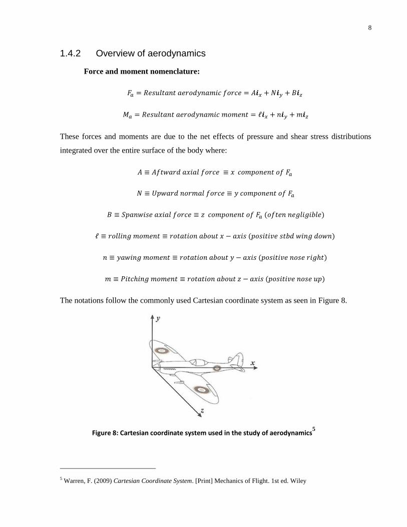
1.4.2 Overview of aerodynamics
Force and moment nomenclature:
These forces and moments are due to the net effects of pressure and shear stress distributions
integrated over the entire surface of the body where:
The notations follow the commonly used Cartesian coordinate system as seen in Figure 8.
Figure 8: Cartesian coordinate system used in the study of aerodynamics5
5 Warren, F. (2009) Cartesian Coordinate System. [Print] Mechanics of Flight. 1st ed. Wiley

9
In two dimensions, the aerodynamics forces acting on an airfoil section are completely defined in
terms of either axial and normal forces, or lift and drag. These two representations of
aerodynamics forces are related solely by the angle of attack, , which is the angle between
and the section cord line, as presented in Figure 9:
Figure 9: Section Forces and Moments6
In terms of dimension-less coefficients these become:
Eq. 1
Eq. 2
Eq. 3
Eq. 4
Eq. 5
6 Warren, F. (2009) Section forces and moments. [Print] Mechanics of Flight. 1st ed. Wiley

10
In relation to airfoils, and are the free stream density and velocity, respectively; is the
planform area, and is the mean chord length.
denotes the aerodynamic coefficient per unit span. Therefore, the relationship between lift and
drag, and, axial and normal forces, can be described as:
Eq. 6
Eq. 7
or,
Eq. 8
Eq. 9
Two important locations along the cord line are: the Center of Pressure, , defined as the point
about which the resultant moment is zero; and the Aerodynamic center, , defined as the point
about which the resultant moment is independent of .
In dimensionless terms, it can readily be shown that the equations derived for , and are:
Eq. 10
Eq. 11
For incompressible flow, the quarter cord is generally assumed to be the aerodynamic center7.
While this is only an approximation, it is quite accurate and often used for subsonic flight under
Mach number 0.3. Also, for symmetric airfoils, the quarter cord can also be shown to be the
center of pressure.
7F., Warren. Mechanics of Flight. 1st ed. Wiley, 2009. Print.
11
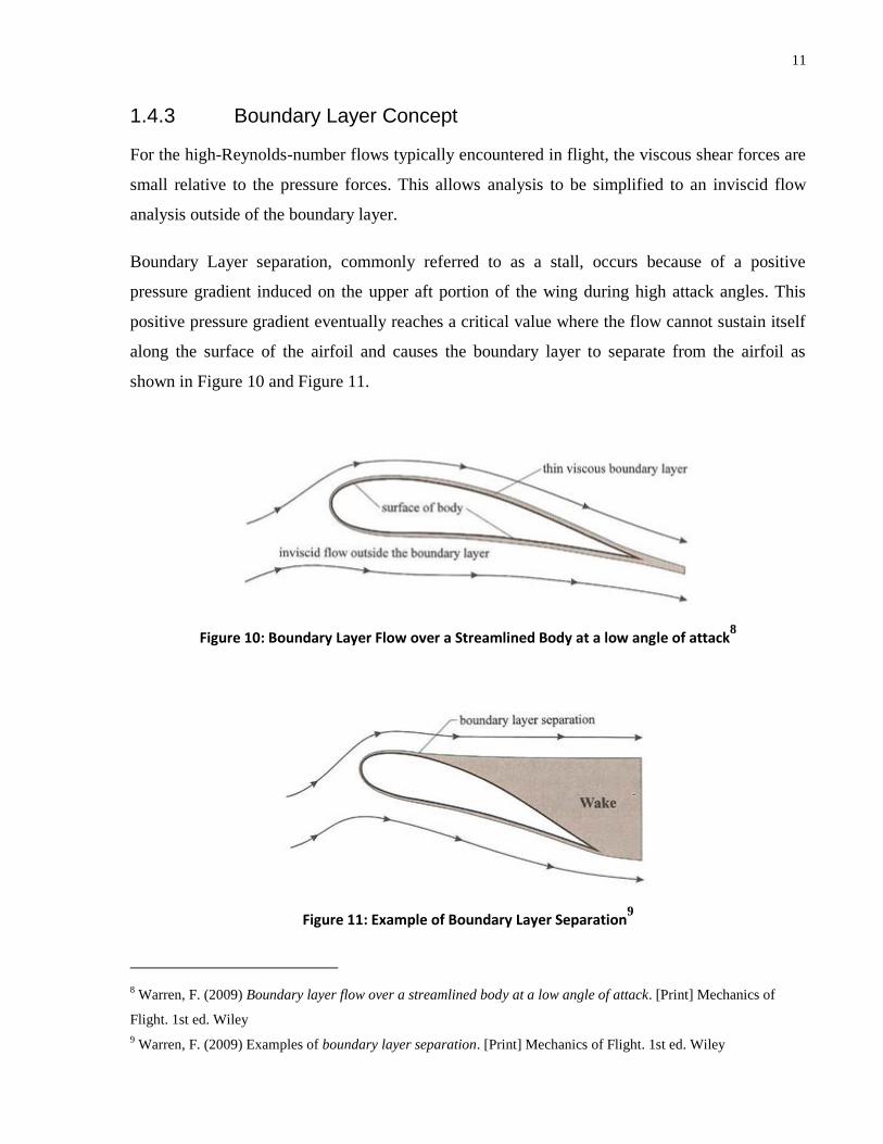
1.4.3 Boundary Layer Concept
For the high-Reynolds-number flows typically encountered in flight, the viscous shear forces are
small relative to the pressure forces. This allows analysis to be simplified to an inviscid flow
analysis outside of the boundary layer.
Boundary Layer separation, commonly referred to as a stall, occurs because of a positive
pressure gradient induced on the upper aft portion of the wing during high attack angles. This
positive pressure gradient eventually reaches a critical value where the flow cannot sustain itself
along the surface of the airfoil and causes the boundary layer to separate from the airfoil as
shown in Figure 10 and Figure 11.
Figure 10: Boundary Layer Flow over a Streamlined Body at a low angle of attack8
Figure 11: Example of Boundary Layer Separation9
8 Warren, F. (2009) Boundary layer flow over a streamlined body at a low angle of attack. [Print] Mechanics of
Flight. 1st ed. Wiley
9 Warren, F. (2009) Examples of boundary layer separation. [Print] Mechanics of Flight. 1st ed. Wiley

12
1.4.4 Considerations for Finite Wings
Wing tip vortices
For an infinite wing, it is correctly assumed that the flow of air only takes place in the plane
consisting of the foil cross section. However, for a finite wing, this is not entirely true,
particularly near the wing tips. At the tip of a wing, air is able to flow from the high pressure
regions below the wing to the low pressure regions above the wing, thus creating a vortex
moving in the span wise direction as seen in Figure 12. This vortex is the primary component of
drag, commonly known as “induced drag”, experienced by an aircraft in subsonic flight.
Attempts to reduce this induced drag include wing tapering and the inclusion of winglets to
prevent vortex formation.
Figure 12: Example of Wingtip Vortices10
Downwash
Downwash is a physical phenomenon predicted by both thin airfoil theory as well as the vortex
panel method. The downwash, located directly below the aircraft, is equally balanced by upwash
10 Langley Research Center (1990) Airplane Vortex. [image online] Available at: http://archive.org/details/NIX-EL-
1996-00130 [Accessed: Dec 2010]

13
beyond the tip vortices, shown in Figure 13. As the size of the tip decreases compared to the
overall size of the wing, the magnitude of the induced drag is reduced due to the reduced
effective downwash.
Figure 13: Airfoil Downwash11
1.4.5 Planform Considerations:
Most airfoils are subjected to induced drag caused by air flowing around the tip of the wing in
the span-wise direction. By decreasing the size of the tip of the wing, or by adding “winglets”,
this induced drag can be greatly reduced. Also, by increasing the aspect ratio of the airfoil, the
wing becomes more effective in that it has a lower amount of induced drag relative to the lift
generated. These methods of reducing drag are commonly seen on lower speed aircraft in the
form of various types of winglets or raked wingtips, as well as elliptical, and more commonly
tapered, wing profiles. A recent study on the use of winglets, as well as varying degrees of taper
at sub-sonic speeds, demonstrates the benefit of using winglet technology as well as the
importance of wing tapering12
. The SeaStryder currently incorporates winglets, raked wingtips,
as well as a tapering wing profile.
11 Scott, J. (2005) Trailing Vortex. [image online] Available at:
http://www.aerospaceweb.org/question/nature/q0237.shtml [Accessed: Dec 2010]
12 Azlin, M.A., C.F. Mat Taib, S. Kasolang, and F.H. Muhammad. "CFD analysis of winglets at low subsonic flow."
World Congress on Engineering. (2011): 87-5.
14
High-speed aircraft are influenced by a phenomenon known as wave drag. During high speed
flight, wave drag is significantly more powerful then induced drag, and therefore, airfoils are
designed solely around reducing this type of drag. Common wing designs of high speed aircraft
include highly swept wings with a very thin profile, changing slowly over a larger cord length.
This design allows for reduced drag during high-speed flight, however, poor low speed
performance. The SeaStryder is not designed for high-speed flight where wave drag becomes a
problem and is resultantly characterized as a low-speed (Sub-Sonic) aircraft.
1.4.6 Wing-in-Ground-Effect Aircraft
A Wing-In-Ground effect (WIG) aircraft such as the SeaStryder is a specialized type of aircraft
designed to take advantage of a well-known phenomenon in aviation known as ground effect.
When in flight within approximately one wingspan of the ground, an aircraft experiences a
floating sensation caused by the increased pressure beneath the airfoil. This “cushion effect”
reduces the required angle of attack by providing additional lift, and as well, provides a reduction
in the induced drag. The induced drag, primarily caused by wingtip vortices is reduced due to the
inability of the vortices to form freely on the wing tips. Theoretically, a wing that does not
produce any wingtip vortices has virtually no induced drag. This effect is often seen in wind
tunnel tests where the wing spans the entire width of the wind tunnel. As an aircraft approaches
the ground, these effects are magnified, particularly on aircraft with low airfoils such as the
SeaStryder.
15
Chapter 2 Background Research
2 Background Research
2.1 Current Industry Design of Horizontal Stabilizer
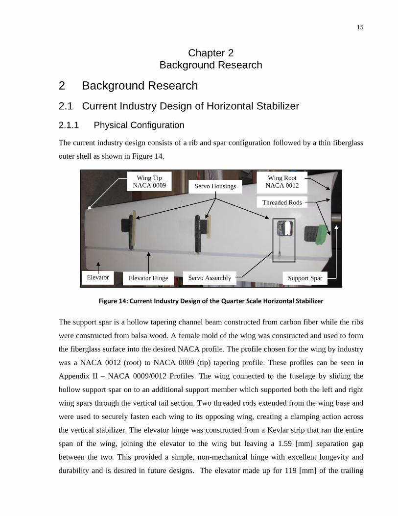
2.1.1 Physical Configuration
The current industry design consists of a rib and spar configuration followed by a thin fiberglass
outer shell as shown in Figure 14.
Figure 14: Current Industry Design of the Quarter Scale Horizontal Stabilizer
The support spar is a hollow tapering channel beam constructed from carbon fiber while the ribs
were constructed from balsa wood. A female mold of the wing was constructed and used to form
the fiberglass surface into the desired NACA profile. The profile chosen for the wing by industry
was a NACA 0012 (root) to NACA 0009 (tip) tapering profile. These profiles can be seen in
Appendix II – NACA 0009/0012 Profiles. The wing connected to the fuselage by sliding the
hollow support spar on to an additional support member which supported both the left and right
wing spars through the vertical tail section. Two threaded rods extended from the wing base and
were used to securely fasten each wing to its opposing wing, creating a clamping action across
the vertical stabilizer. The elevator hinge was constructed from a Kevlar strip that ran the entire
span of the wing, joining the elevator to the wing but leaving a 1.59 [mm] separation gap
between the two. This provided a simple, non-mechanical hinge with excellent longevity and
durability and is desired in future designs. The elevator made up for 119 [mm] of the trailing
Wing Root
NACA 0012
Wing Tip
NACA 0009 Servo Housings
Elevator Servo Assembly Support Spar
Threaded Rods
Elevator Hinge
16
edge of the wing. The core section of the wing, however, varied in chord length from root to tip.
The root NACA profile, located on the centerline of the fuselage, was scaled to provide a 474
[mm] root chord length, and the tip profile, located 1219 [mm] from the centerline, was scaled to
provide a 320 [mm] tip chord length. The elevator servos were mounted within the rib and spar
space frame. Control rods extended through the fiberglass surface and were connected to the
lower edge of the elevator. Due to this design, additional cover plates and flexible gasket
couplings were necessary to protect the control rod and seal off the servo from water and outside
debris. The construction methods and materials involved in the manufacturing of this design
were limited to commonly available tools, equipment and materials and all layup procedures
were performed by hand.
2.1.2 Specifications Provided by Industry
The load capacity of the complete wing assembly was never tested, however since the design is
internally supported by a single support spar, the spar was individually tested prior to assembly
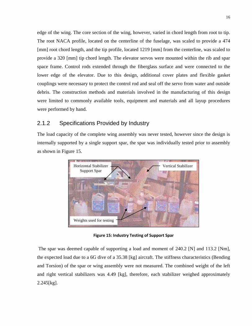
as shown in Figure 15.
Figure 15: Industry Testing of Support Spar
The spar was deemed capable of supporting a load and moment of 240.2 [N] and 113.2 [Nm],
the expected load due to a 6G dive of a 35.38 [kg] aircraft. The stiffness characteristics (Bending
and Torsion) of the spar or wing assembly were not measured. The combined weight of the left
and right vertical stabilizers was 4.49 [kg], therefore, each stabilizer weighed approximately
2.245[kg].
Horizontal Stabilizer
Support Spar
Weights used for testing
Vertical Stabilizer

17
2.1.3 Current Design Issues
Any aircraft’s center of gravity (CG) must be positioned within a limited range in order to
maintain a certain level of stability during flight. Because of this, the consequence of any
unnecessary weight aft of the CG is amplified due to the fact that it must be compensated for
forward of the CG to maintain stability. In the case of the Stryder600, this compensating weight
is added in the nose cone of the aircraft to provide the most benefit. It has been determined by
industry that the aft weight of the aircraft is too great and is causing unnecessary amounts of
weight to be added to the nose cone as compensation. It is believed that the current horizontal
stabilizers are one of the primary reasons for this excess aft weight and that an optimization of
the current design is needed. The horizontal stabilizers are located near the most aft section of
the aircraft as seen in Figure 16 and therefore any unnecessary weight in this component is
highly unfavorable.
Figure 16: Stryder600 Side View
An additional minor issue with the horizontal stabilizer is the servo control rod mechanism
shown previously in Figure 14. The control rods currently extend past the fiberglass surface as
shown in Figure 17, exposing the servo and control mechanism.
Figure 17: Close up of Industry Design Showing Servo Assembly
Servo control
rod
Horizontal
stabilizer
position
Elevator
18
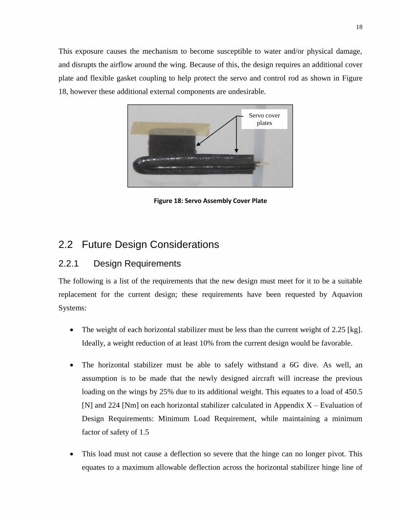
This exposure causes the mechanism to become susceptible to water and/or physical damage,
and disrupts the airflow around the wing. Because of this, the design requires an additional cover
plate and flexible gasket coupling to help protect the servo and control rod as shown in Figure
18, however these additional external components are undesirable.
Figure 18: Servo Assembly Cover Plate
2.2 Future Design Considerations
2.2.1 Design Requirements
The following is a list of the requirements that the new design must meet for it to be a suitable
replacement for the current design; these requirements have been requested by Aquavion
Systems:
The weight of each horizontal stabilizer must be less than the current weight of 2.25 [kg].
Ideally, a weight reduction of at least 10% from the current design would be favorable.
The horizontal stabilizer must be able to safely withstand a 6G dive. As well, an
assumption is to be made that the newly designed aircraft will increase the previous
loading on the wings by 25% due to its additional weight. This equates to a load of 450.5
[N] and 224 [Nm] on each horizontal stabilizer calculated in Appendix X – Evaluation of
Design Requirements: Minimum Load Requirement, while maintaining a minimum
factor of safety of 1.5
This load must not cause a deflection so severe that the hinge can no longer pivot. This
equates to a maximum allowable deflection across the horizontal stabilizer hinge line of
Servo cover
plates
19
12.7 [mm] as shown in Appendix X – Evaluation of Design Requirements: Maximum
Deflection Requirement. Any deflection beyond this will not allow the elevator to pivot
and cause a loss of control.
The elevator range of motion should meet or exceed the current design of a +/- 25 degree
incline/decline of the leading control surface.
The elevator hinge moment provided by the servo control arms must exceed the
maximum expected moment caused throughout all operational conditions. As well, the
new design should employ the use of at least three servos along the hinge line similar to
the current design.
These servo motors must be serviceable, as well as protected from weather.
The horizontal stabilizers should utilize the proven Kevlar hinge concept similar to the
current design.
The horizontal stabilizers should contain an accelerometer(s) for measuring bending and
torsional vibration.
The horizontal stabilizers must be easily removable and connect to the vertical stabilizer
in the same fashion as the current industry design at a 3.5 degree positive rigging angle.
The horizontal stabilizers must follow the same NACA 0012/0009 profile as seen in
Appendix II – NACA 0009/0012 Profiles.
The materials and manufacturing methods used must be practical and cost effective.
Minimizing the cost of manufacturing is a key objective. As well, the cost of prototyping
must be kept to an absolute minimum as no further funding is available.
The horizontal stabilizers must be able to support the addition of winglets.
A structural prototype should be constructed to confirm all results.
20
2.2.2 State-of-art
The internal configuration of current leading edge designs with similar design requirements
generally consist of a primary spar, a cellular foam core material, and a load bearing skin
material as the outer shell. A recent comparable study performed by C. Kong on the structural
design of a horizontal tail wing demonstrates this highly effective design13
. Utilizing the skin as
a load bearing surface is inherently the optimal way to improve the rigidity as the second
moment of area, also known as the moment of inertia, is exponentially related to the distance
from the cross-sectional plane to the load bearing material. This can be seen in Equation 12 for
the Second Moment of Area.
Eq. 12
It is clear that the most beneficial configuration to maximize the Second Moment of Area is to
use the most distant area possible, the wing surface, as the load bearing structure. In this
configuration carbon fiber is commonly used for high-end aircraft as it is commercially available
and provides a high level of strength and rigidity relative to its weight, much higher than the
common alternative material, fiberglass. The core materials used in this type of composite
sandwich panel structure vary from once design to another. The analysis performed by C. Kong
utilized a carbon fiber shell which surrounded Divinycell, an aerospace grade structural foam.
Honeycomb and aluminum core materials are often used as well, as described in a recent
sandwich panel study performed by Jong Woong Lee14
. This study tested sandwich panels
commonly used as wing skins and fuselage components consisting of graphite/epoxy facesheets
surrounding aluminum honeycomb core materials. While extremely light, a leading disadvantage
noted in this study was the unpredictability of a buckling failure. The buckling failures occurred
at stresses consistently significantly lower (nearly half) than predictions made by FEM analysis.
The primary cause of failure was delamination of the facesheets due to the limited bonding area
13 Kong, C., H. Park, Y. Kim, and K. Kang. "Structural Design on Wing of a Small Scale WIG Vehicle with
Carbon/Epoxy and Foam Sandwich Composite Structure." 16th International Conference on Composite Materials.
(2007).
14 Lee, Jong Woong, Cheol Won Kong, Se Won Eun, Jae Sung Park, Young Soon Jang, Yeong Moo Yi, and
Gwang-Rae Cho. "Compression test of composte sandwich panel." Key Engineering Materials. 348-349. (2007):
605-4

21
of the honeycomb structure, which eventually lead to global buckling. Because of this, only
small-cell or closed cell core materials are generally used when buckling is a potential failure
mode. In a study performed by R. Warsi Sullivan testing carbon-composite Unmanned Air
Vehicle (UAV) wings, where buckling was known to be a potential failure mode, Divinycell was
again the material chosen as the primary core material15
. This study, along with a similar recent
study performed by Myoungkeon Lee on the composite wing structure of an UAV16
, are of
particular relevance, as weight reduction in an UAV is critical to its operational limitations.
Myoungkeon Lee concluded that when utilizing a load bearing carbon fiber skin, the buckling
load was the limiting factor and efforts to improve buckling strength were substantially more
critical than improving material strength. As well, this study noted the importance of orienting
the carbon fiber plies at ±45° to the buckling axis to improve the buckling strength. In the design
proposed by R. Warsi Sullivan, a rib and spar structure supported an upper and lower sandwich
panel skin as shown in Figure 19.
Figure 19: Configuration of R. Warsi Sullivans Design17
15 Sullivan, R. Warsi, Y. Hwang, M. Rais-Rohani, and T. Lacy. "Structural Analysis and Testing of and Ultralight
Unmanned-Aerial-Vehicle Carbon-Composite Wing." Journal of Aircraft. 46. no. 3 (2009): 814-7.
16 Lee, Myoungkeon, Changmin Cho, and Seyong Jang. "HALE UAV Composite Wing Structure Design."
Advanced Materials Research. 123-125. (2010): 105-4.
17 Sullivan, R. (2009) Panel Configuration. [Journal Article] Structural Analysis and Testing of and Ultralight
Unmanned-Aerial-Vehicle Carbon-Composite Wing
Rib
Spars
Upper/Lower
Surfaces
22
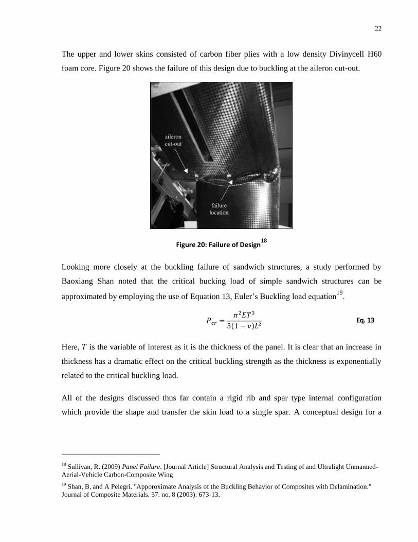
The upper and lower skins consisted of carbon fiber plies with a low density Divinycell H60
foam core. Figure 20 shows the failure of this design due to buckling at the aileron cut-out.
Figure 20: Failure of Design18
Looking more closely at the buckling failure of sandwich structures, a study performed by
Baoxiang Shan noted that the critical bucking load of simple sandwich structures can be
approximated by employing the use of Equation 13, Euler’s Buckling load equation19
.
Eq. 13
Here, is the variable of interest as it is the thickness of the panel. It is clear that an increase in
thickness has a dramatic effect on the critical buckling strength as the thickness is exponentially
related to the critical buckling load.
All of the designs discussed thus far contain a rigid rib and spar type internal configuration
which provide the shape and transfer the skin load to a single spar. A conceptual design for a
18 Sullivan, R. (2009) Panel Failure. [Journal Article] Structural Analysis and Testing of and Ultralight Unmanned-
Aerial-Vehicle Carbon-Composite Wing
19 Shan, B, and A Pelegri. "Apporoximate Analysis of the Buckling Behavior of Composites with Delamination."
Journal of Composite Materials. 37. no. 8 (2003): 673-13.
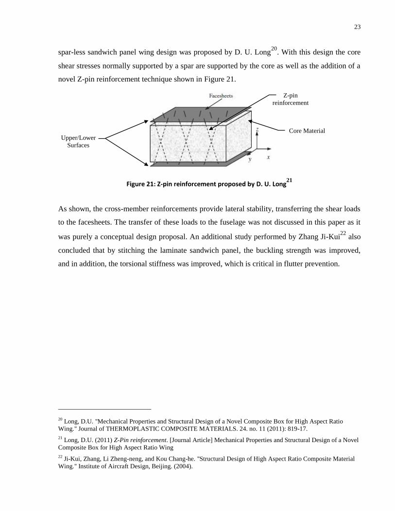
23
spar-less sandwich panel wing design was proposed by D. U. Long20
. With this design the core
shear stresses normally supported by a spar are supported by the core as well as the addition of a
novel Z-pin reinforcement technique shown in Figure 21.
Figure 21: Z-pin reinforcement proposed by D. U. Long21
As shown, the cross-member reinforcements provide lateral stability, transferring the shear loads
to the facesheets. The transfer of these loads to the fuselage was not discussed in this paper as it
was purely a conceptual design proposal. An additional study performed by Zhang Ji-Kui22
also
concluded that by stitching the laminate sandwich panel, the buckling strength was improved,
and in addition, the torsional stiffness was improved, which is critical in flutter prevention.
20 Long, D.U. "Mechanical Properties and Structural Design of a Novel Composite Box for High Aspect Ratio
Wing." Journal of THERMOPLASTIC COMPOSITE MATERIALS. 24. no. 11 (2011): 819-17.
21 Long, D.U. (2011) Z-Pin reinforcement. [Journal Article] Mechanical Properties and Structural Design of a Novel
Composite Box for High Aspect Ratio Wing
22 Ji-Kui, Zhang, Li Zheng-neng, and Kou Chang-he. "Structural Design of High Aspect Ratio Composite Material
Wing." Institute of Aircraft Design, Beijing. (2004).
Core Material
Z-pin
reinforcement
Upper/Lower
Surfaces

24
Chapter 3 Materials and Methods
3 Materials and Methods
3.1 Design Concept
The following section describes the details of the proposed design. This design is based on state-
of-art techniques, cost and manufacturing constraints as well as available materials.
3.1.1 Design Overview
Two primary considerations when designing the internal configuration of the wing were strength
and stiffness. Strength limits the amount of lift the wind can provide, particularly relevant during
a dive recovery maneuver. From the design requirements, the maximum lift required equates to a
load of approximately 450 [N]23
. This occurs during a 6G dive recovery operation, where the
aircraft is experiencing six times the normal gravitational force. Wing Stiffness is of equal
importance. If the wing does not have adequate stiffness, then it may be prone to flutter, a
catastrophic condition whereby the wing begins to vibrate at its natural dynamic frequency. This
critical flutter frequency is a function of stiffness, damping, and wing speed. As well, if the
deflection of the wing is too great, the elevators can no longer pivot, as the hinge line becomes
an arc. Based on the wing requirements, additional weight reduction requirements, and cost
constraints, the proposed design utilizes a load-bearing skin, fully surrounding an ultra-light
core, to form a single composite sandwich structure similar to the design proposed by D. U.
Long. An obvious disadvantage of this design is the inability to utilize the space inside the
wings, however, this is not relevant for stabilizers as they are too far aft. As well, additional
loading would cause poor weight distribution and would defeat the purpose of the weight
reduction. This design can be manufactured cost effectively both in terms of material and
manufacturing methods. By using the wing skin as the support frame, the maximum possible
stiffness to weight ratio is achieved as the moment of inertia is exponentially related to the
distance from the mid-plane to the load bearing material. However, this design is highly
susceptible to surface buckling in compression as seen in the study performed by R. Warsi
23 Appendix X – Evaluation of Design Requirements, Minimum Load Requirement
25
Sullican24
. Therefore, methods to increase the buckling strength are critical. As mentioned in the
study performed by Myoungkeon Lee, one method of improving the buckling strength is to
orient the carbon fiber plies at ±45° to the buckling axis25
. In addition, by using the entire
thickness of the wing as a sandwich panel, as opposed to separate upper and lower sandwich
panel as developed by C. Kong26
, the panel thickness is maximized, a critical factor in
determining buckling strength. An additional complication of this design arises due to the load
transfer from the wing to the fuselage. Traditional rib and spar configurations transfer the wing
load to the fuselage through a main support spar. With the solid core skin support frame concept,
no such spar exists, and therefore an alternative method must be used. An innovative solution to
this problem involves the use of a specialized base support discussed in this section. The
materials selected for this design consisted of carbon fiber as the structural material, and
Divinycell-H80 and polystyrene for the core materials. Carbon fiber was selected for the
structural material because it provides the highest level of stiffness and strength relative to its
weight, compared to materials that are commonly available. Divinycell H80 was selected as the
base core material as it is an aerospace grade structural foam which provides a cost effective
lightweight solution. It is inherently extremely stiff, and is commonly used in conjunction with
carbon fiber and in sandwich structures to prevent buckling. Finally, polystyrene was selected as
a primary core material due to its excellent formability and extremely low density.
3.1.2 Servo Housing and Elevator Control
The two primary elevator control issues with the current design are the service hatch locations
and the protrusion of the elevator linkage arms. The proposed design addresses both of these
issues through the use of an extremely light and compact servo housing assembly, designed to
allow the servo motor to be accessed and serviced from the trailing edge of the wing, between
the elevator and wing as shown in the Figure 22. The servo housing assembly has been designed
24 Sullivan, R. Warsi, Y. Hwang, M. Rais-Rohani, and T. Lacy. "Structural Analysis and Testing of and Ultralight
Unmanned-Aerial-Vehicle Carbon-Composite Wing." Journal of Aircraft. 46. no. 3 (2009): 814-7.
25 Lee, Myoungkeon, Changmin Cho, and Seyong Jang. "HALE UAV Composite Wing Structure Design."
Advanced Materials Research. 123-125. (2010): 105-4.
26 Kong, C., H. Park, Y. Kim, and K. Kang. "Structural Design on Wing of a Small Scale WIG Vehicle with
Carbon/Epoxy and Foam Sandwich Composite Structure." 16th International Conference on Composite Materials.
(2007).
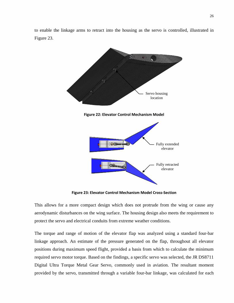
26
to enable the linkage arms to retract into the housing as the servo is controlled, illustrated in
Figure 23.
Figure 22: Elevator Control Mechanism Model
Figure 23: Elevator Control Mechanism Model Cross-Section
This allows for a more compact design which does not protrude from the wing or cause any
aerodynamic disturbances on the wing surface. The housing design also meets the requirement to
protect the servo and electrical conduits from extreme weather conditions.
The torque and range of motion of the elevator flap was analyzed using a standard four-bar
linkage approach. An estimate of the pressure generated on the flap, throughout all elevator
positions during maximum speed flight, provided a basis from which to calculate the minimum
required servo motor torque. Based on the findings, a specific servo was selected, the JR DS8711
Digital Ultra Torque Metal Gear Servo, commonly used in aviation. The resultant moment
provided by the servo, transmitted through a variable four-bar linkage, was calculated for each
Fully extended
elevator
Fully retracted
elevator
Servo housing
location
27
possible linkage scenario at all flap angles and is provided in Appendix III – Hinge Moment
Calculations and Characteristics. As specified, this design also uses a non-mechanical Kevlar
hinge and is designed to provide a +/- 25 degree flap angle.
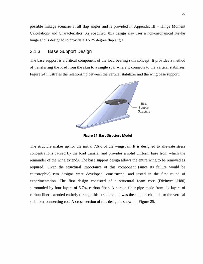
3.1.3 Base Support Design
The base support is a critical component of the load bearing skin concept. It provides a method
of transferring the load from the skin to a single spar where it connects to the vertical stabilizer.
Figure 24 illustrates the relationship between the vertical stabilizer and the wing base support.
Figure 24: Base Structure Model
The structure makes up for the initial 7.6% of the wingspan. It is designed to alleviate stress
concentrations caused by the load transfer and provides a solid uniform base from which the
remainder of the wing extends. The base support design allows the entire wing to be removed as
required. Given the structural importance of this component (since its failure would be
catastrophic) two designs were developed, constructed, and tested in the first round of
experimentation. The first design consisted of a structural foam core (Divinycell-H80)
surrounded by four layers of 5.7oz carbon fiber. A carbon fiber pipe made from six layers of
carbon fiber extended entirely through this structure and was the support channel for the vertical
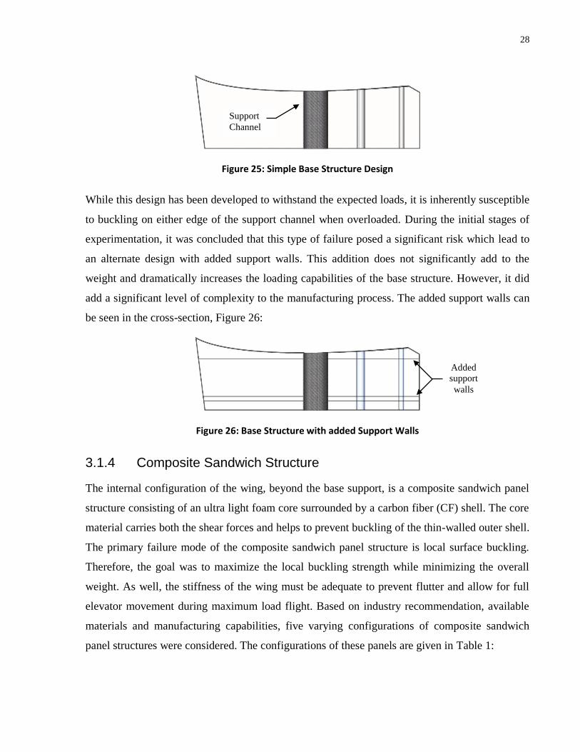
stabilizer connecting rod. A cross-section of this design is shown in Figure 25.
Base
Support
Structure
28
Figure 25: Simple Base Structure Design
While this design has been developed to withstand the expected loads, it is inherently susceptible
to buckling on either edge of the support channel when overloaded. During the initial stages of
experimentation, it was concluded that this type of failure posed a significant risk which lead to
an alternate design with added support walls. This addition does not significantly add to the
weight and dramatically increases the loading capabilities of the base structure. However, it did
add a significant level of complexity to the manufacturing process. The added support walls can
be seen in the cross-section, Figure 26:
Figure 26: Base Structure with added Support Walls
3.1.4 Composite Sandwich Structure
The internal configuration of the wing, beyond the base support, is a composite sandwich panel
structure consisting of an ultra light foam core surrounded by a carbon fiber (CF) shell. The core
material carries both the shear forces and helps to prevent buckling of the thin-walled outer shell.
The primary failure mode of the composite sandwich panel structure is local surface buckling.
Therefore, the goal was to maximize the local buckling strength while minimizing the overall
weight. As well, the stiffness of the wing must be adequate to prevent flutter and allow for full
elevator movement during maximum load flight. Based on industry recommendation, available
materials and manufacturing capabilities, five varying configurations of composite sandwich
panel structures were considered. The configurations of these panels are given in Table 1:
Added
support
walls
Support
Channel

29
Configurations of Composite Sandwich Panel Structures under Consideration
Configuration 1 Configuration 2 Configuration 3 Configuration 4 Configuration 5
Layer 1 3 Layers of CF 3 Layers of CF 2 Layers of CF 2 Layers of CF 2 Layers of CF
Layer 2 0.25in Divinycell Polystyrene Polystyrene 0.125in Divinycell 0.25in Divinycell
Layer 3 Polystyrene 3 Layers of CF 2 Layers of CF Polystyrene Polystyrene
Layer 4 0.25in Divinycell 0.125in Divinycell 0.25in Divinycell
Layer 5 3 Layers of CF 2 Layers of CF 2 Layers of CF
Table 1: Composite Sandwich Panel Structures
3.1.5 Accelerometers
One of the design requirements is the ability to detect and measure potentially catastrophic
vibrational disturbances in the wing. This is accomplished by means of 2, 3-axis accelerometers
placed at tip of the wing, one at the leading edge, and one at the trailing edge. The effects of
torsional and bending vibration on the accelerometers can be each isolated by making use of the
superposition principle as each effect acts independently. Appendix V – Example of
Accelerometer Input / Output - depicts an example of a likely input to the accelerometer, and the
output after employing the superpositioning principle. This example demonstrates clearly how
the accelerometers can be used together to obtain the torsional and bending vibration in real time.
3.2 Materials and Apparatus
3.2.1 Apparatus
For the purpose of conducting experiments, a 38.1 [mm] diameter stainless steel bar was rigidly
supported to a fixed steel slat table using a cast-iron bench vise. This arrangement formed a
stable support member representing the support spar used on the vertical stabilizer. A checker
pattern backdrop was placed behind the set-up to help record deflection characteristics, where
each square in the pattern measured 6.35 [mm]. The loading of the beams was captured in high
definition at a rate of 60 frames per second. For the loading procedure, 2.27kg weights were
used and added as indicated in Appendix IV – Beam Loading Positions. While this limited the
resolution of the experiment, it was adequate in providing the experimental data needed to make
30
strength estimates, design decisions and ensure design requirements were being met. To make
many of the composite parts, a vacuum pump and necessary accessories were provided by the
University of Toronto. A precision scale was used throughout the construction process to record
all material masses, as well as to properly mix the epoxy resin system to the correct ratio. A
digital caliper with a 0.01[mm] resolution was used for taking measurements, as well as for
measuring the deflection during a three-point bend test. Finally, a simple hot wire cutter was
constructed for cutting and shaping the polystyrene parts.
3.2.2 Materials Used
1) BGF 5.7oz plain weave Carbon Fiber 3K-70-P (Composites Canada Product CA057-50)
2) PR2032 Aeropoxy Resin with PH3665 Hardener27
Combined Carbon Fiber/Epoxy Properties
Density [g/mm^3] (2 Layer): 0.00165 (measured)
Density [g/mm^3] (3 Layer): 0.00215 (measured)
Tensile Strength [MPa]: 310
Tensile Modulus [GPa]: 70
3) 3.175 and 6.35 [mm] Divinycell H80 Structural Foam Sheet28
Density [g/mm^3]: 8.00E-05
Tensile Strength [MPa]: 2.5
Compressive Strength [MPa]: 1.4
Shear Strength [MPa]: 1.15
Tensile Modulus [MPa]: 95
Shear Modulus [MPa]: 27
4) 609.6x2438.4x50.8[mm] Closed-Cell Extruded polystyrene (STYROFOAM LT)29
27 Provided by AEROPOXY - See
Appendix IX – Material Data Sheets, AEROPOXY Data Sheet
28 Provided by DIAB Group - See
Appendix IX – Material Data Sheets, DIAB Group Data Sheet
29 Provided by DOW Industries - See

31
Density [g/mm^3]: 2.80E-05 ( 2.78E-05 measured)
Tensile Strength [kPa]: 450
Compressive Strength [kPa] 250
Shear Strength [kPa]: 250
Shear Modulus [MPa]: 7.0
Tensile Modulus [MPa]: 12-15
Maximum use Temperature [°C]: 74
5) Airtech Econostitch Peel Ply (Composites Canada Product VAPP-ES)
6) Airtech Airweave N4 Breather Material (Composites Canada Product VABR-N4)
7) Airtech Vacuumed Bagging Film (Composites Canada Product VABF-WL6400-60)
8) Airtech AT-200Y Sealant Tape (Composites Canada Product VATP-AT200Y)
9) Gorilla glue (Polystyrene adhesive)
3.3 Preliminary Experimentation
3.3.1 Base Support Experiment
The objective of the base support experiment was to study the loading capacities and failure
modes of the two composite beam base structures and test the validity of the composite base
structure design concept. The critical applied load was defined as the load which first caused
severe deformation or crack propagation when the beam was loaded in a cantilever beam
orientation. It should be noted that in this experiment the loading capacity of the beam itself was
not relevant as only the base structure was of interest to the end result.
Both of the proposed base structures were designed to carry the expected maximum load
(including a safety factor of 1.50) of 450[N] evenly distributed across the span of the beam. The
second design has additional support members to help prevent the occurrence of internal
buckling of the main load bearing support walls. Both composite base structures were expected
to fail due to buckling under extreme loading.
Appendix IX – Material Data Sheets, DOW Industries Data Sheet
32
3.3.1.1 Procedure
The process used to create the prototype base support is described below. For simplicity, a
rectangular cross section was used as opposed to an airfoil for this stage of the experimentation.
1) The initial step was to construct the core of the base support as shown in Figure 27 (a-e).
(a) A sheet of 6.35 [mm] Divinycell H80 was cut and epoxied together to form a
76.2 49.38 203.2 [mm] solid block of Divinycell. (b) A 40.54 [mm] diameter hole was
then drilled into the block for the addition of the support spar channel. (c) The support
spar channel, measuring 38.1 [mm] inner diameter and 40.54 [mm] outer diameter, was
made from six layers of carbon fiber and inserted into the Divinycell core. Finally, four
layers of carbon fiber were added surrounding the Divinycell core and carbon fiber pipe.
(d) At this stage, a vacuum bagging process was used to ensure the carbon fiber was fully
impregnated and completely bonded to the core. (e) This completed the base structure.
(a) (b) (c)
(d) (e)
Figure 27: Construction of First Support Base
The second base support was made in a similar fashion, however, during the first step,
four layers of carbon fiber were added into three locations along the length of the base
support as shown in Figure 28 (a) and (b), before and after the finishing cuts and insertion of
the carbon fiber support spar channel.

33
(a) (b)
Figure 28: Construction of Second Support Base
2) Next the base supports were adhered to composite sandwich panels consisting of two
layers of 6.35 [mm] Divinycell H80 with a polystyrene foam core as shown in Figure 29
(a-c). Care was taken to avoid any imperfections along this joint that would later cause
stress concentrations in the carbon fiber shell. These structures were then surrounded by
three layers of carbon fiber and vacuum bagged once again.
(a) (b)
(c)
Figure 29: Addition of composite Sandwich Panel
3) Once fully cured, the bases were each tested to failure in a cantilever beam type
configuration. This was performed by connecting the beams to the fixed steel bar
representing the support spar used on the vertical stabilizer. The beams were then
uniformly loaded until failure, as shown in Figures 30-33 The failure modes were then
Support
walls
Support
walls

34
analyzed and the failure stresses were calculated. The results from this experiment were
then used to select a base support design.
3.3.1.2 Base 1
Figure 30: Base 1 - Unloaded
Figure 31: Base 1 - Fully Loaded Prior to Failure
3.3.1.3 Base 2
Figure 32: Base 2 - Unloaded
Beam loaded in cantilever type configuration
Fixed steel bar representing the support spar
Internal Failure of the Base Structure
Beam loaded in cantilever type configuration
Fixed steel bar representing the support spar

35
Figure 33: Base 2 - Fully Loaded Prior to Beam Failure
3.3.2 Composite Sandwich Panel Experiment
The primary purpose of the Composite Sandwich Panel experiment was to determine the critical
strength of five varying designs of cantilevered composite sandwich panel beams. The stiffness,
maximum deflection before failure, and particular failure modes were also documented. Each
beam was made to the same overall dimensions and loaded in a similar fashion. The critical
applied load was defined as: the load which first caused severe local or global buckling of the
structure when loaded with a uniformly distributed load in a cantilever beam orientation. The
composition of each of the composite sandwich panels are depicted in Figures 34- 38.
Figure 34: Composition of Beam 1
No signs of failure
36
Figure 35: Composition of Beam 2
Figure 36: Composition of Beam 3
Figure 37: Composition of Beam 4

37
Figure 38: Composition of Beam 5
3.3.2.1 Procedure
The Procedure for making each of the beams followed essentially the same process. Again, a
rectangular cross-section was used at this stage of the experimentation for simplicity. By using a
rectangular cross-section, the area of stress concentration was easily predictable and straight-
forward to calculate. As well, the beams were simpler to construct and still provided the buckling
strength of the panel. The following procedure was used to construct the beams:
1) The first step was to cut the polystyrene core to the required dimensions. This was done
using a hotwire foam cutting tool. Each beam was cut to approximately 203.2 [mm] wide
by 1105 [mm] long and was cut to the required thickness such that the end result would
measure 50.8 [mm] in thickness30
.
2) If the sandwich panel core contained of layers of either 3.18 [mm] or 6.35 [mm] thick
Divinycell core material, the Divinycell was cut to the same length and width of the beam
and, adhered using a polystyrene adhesive.
30 Final measured dimensions can be found in Appendix VI – Experimental Results: Beam Bending Study,
Summary of Experimental Results
38
3) The sandwich panel core was then adhered to the previously constructed base structure.
Similar to the previous experiment, care was taken to ensure a smooth transition from the
core to the base structure to avoid stress concentrations in the carbon fiber shell.
4) The required numbers of carbon fiber layers were then added to the upper and lower
surfaces of the core material, and to the base structure. The fiber ply orientation was
0/90° along the axis of the beam. These carbon fiber layers were then impregnated with
an epoxy resin system and vacuum bagged until fully cured.
5) The modulus of elasticity of each composite sandwich panel was approximated via a
three-point bend test and compared with analytical values. This test involved simply
supporting each beam across a 787.4 [mm] span, loading the center of the beam with
weights and measuring the deflection of the beam using a digital caliper as shown in
Figure 39. The results of this study can be found in Appendix VI – Experimental Results:
Beam Bending Study.
Figure 39: Experimental Set-Up for Testing Elasticity
6) The composite sandwich panels were then each tested to failure in a cantilever beam type
configuration. This was performed by connecting the beams to the fixed steel bar
representing the support spar, similar to the base structure testing. The composite
sandwich panels were then uniformly loaded until failure. The failure modes were
analyzed and the failure stresses were calculated. The results from this experiment were
then used to select a composite sandwich panel for use in the wing design.
Vernier calipers to
measure deflection
when loaded

39
3.4 Design Validation and Experimentation
From the previous experimentation, the configuration of the support base and composite
sandwich panel was determined. A prototype of the structural components of the wings were
constructed and tested based on these results to experimentally verify the design. Complete
design details and specifications are provided in Appendix I – Design Details and
Documentation.
3.4.1.1 Procedure
The first step in constructing the prototype was to create a replica of the current vertical tail
section of the SeaStryder600. This was constructed using rigid foam insulation to form the basic
shape. A fibreglass matt outer layer was then applied in order to provide the required structural
rigidity. The base structures were then constructed to precisely match the contours of the vertical
tail section and the remaining wing sections were completed and tested. The procedure is
outlined below.
1) The original computer aided design (CAD) data of the vertical tail section was used to
create cross-sectional templates that were then used to cut out 1.5 inch layers of the
section, to build up the foam core mold of the vertical tail section as shown in Figure 40
(a-b).
(a) (b)
Figure 40: Vertical Stabilizer Initial Core Templates
2) This mold was then cut using a hotwire foam cutting tool, sanded to a smooth finish, and
clearance cuts were made. This process can be seen in Figure 41 (a-d). (a) The cross-
sectional layers were precisely cut to form a near finished airfoil shape. (b) A template of
the span-wise clearance holes was made and used to cut out the segments which later

40
form the support bar channel, fastening locations and electrical conduits. (c-d) Lastly, the
1.5 inch sections were permanently adhered together using the polystyrene adhesive.
(a) (b)
(c) (d)
Figure 41: Finishing the Vertical Stabilizer Core
3) Once cured, the entire structure was surrounded by six layers of fibreglass matt and
vacuum bagged as shown in Figure 42 (a)-(b). (c) A composite tubular support channel
was then added and the whole structure was again sanded to a smooth finish. (d) Finally,
a white gel coat was added as the top layer, completing the vertical tail section replica.
(a) (b)
(c) (d)
Figure 42: Finalizing the Vertical Stabilizer Replica

41
4) The base structures were the next components to be built, as shown in Figure 43 (a-c). (a)
Aluminum templates of the airfoil structure adjacent to the base structures were made and
used to form the foam core structure of the base using a foam hotwire cutting tool. (b)
While the designed called for the use of Divinycell as the base core material, the
manufacturing methods available were unable to cut the Divinycell, and therefore
polystyrene had to be used in its place. (c) Four layers of carbon fiber were added as
required into four locations along the length of the beam providing the additional support
walls and one finished edge.
(a) (b) (c)
Figure 43: Wing Base Support
5) Once the layers were added the remaining base structure was completed as depicted in
Figure 44 (a-c). (a) The support bar channel, fastening hardware cut-out and electrical
conduits holes were drilled. To form the complex freeform surface adjacent to the vertical
stabilizer, the base structures were connected to the vertical stabilizer and material was
gradually cut off in 3.18 [mm] incremental cuts using a hotwire. (b) The hotwire was
offset 3.18 [mm] from the surface of the vertical stabilizer and slid along the support base
joint, creating a very close fit between the surface of the vertical stabilizer and the base
support. (c) The remaining unfinished foam sides were then surrounded by four
additional layers of carbon fiber and the parts were vacuum bagged until cured.
(a) (b) (c)
Figure 44: Completing the Base Support
42
6) Next, using a similar procedure used to create the base cores, the polystyrene foam was
cut to form the core material and the wing structures were completed. The process is
depicted in Figure 45 (a-e). (a) Again, aluminum templates were made and used to guide
the hotwire cutting tool through the polystyrene. (b) The cores were then bonded together
using a polystyrene adhesive and the whole structure was sanded to a smooth finish,
particularly across the bonded joints. (c-d) Finally, two layers of carbon fiber were added
to the entire structure to form the load bearing shell. The first layer was oriented at 0/90°
to the vertical stabilizer centerline, the second at ±45°. (e) This was again vacuum bagged
until fully cure.
(a) (b) (c)
(d) (e)
Figure 45: Completing the Wing
7) Each wing was then tested to failure, again in a cantilever beam type configuration
similar to the composite sandwich panel testing. The wings were uniformly loaded until
failure. The failure modes were then analyzed and the failure stresses were calculated.
3.4.1.2 Construction Complications
During the construction processes, some complications arose. The most unfavorable
complication arose while the Divinycell was being cut for the base structures. When the base
structure was constructed for the beams, the Divinycell was cut to a rectangular shape using a
band saw. For the wing base structure, the Divinycell needed to be cut into a specific airfoil

43
shape, and therefore a hotwire was the only method available to create such a free-form shape.
When this was attempted the hotwire was not able to cut the Divinycell fast enough due to a lack
of power, and caused the surface to burn and become very irregularly shaped as seen in Figure
46. Polystyrene was used in place of the Divinycell as it is easily cut using a hotwire as seen
earlier in Figure 43.
Figure 46: Divinycell Hotwire Cutting Failure
However, polystyrene does not provide the structural stiffness necessary to prevent internal
buckling of the base structure. Therefore, as expected, during the wing experimentation the base
structure began to fail before the catastrophic failure of the wing structure beyond the base. This
initial failure did not affect the final results relating to the failure of the composite sandwich
panel beyond the base structure.
Another complication to the base structure arose when the support bar channels were drilled into
the polystyrene cores. Unintentionally, the holes were cut oversize by 4.22 [mm]. The design
called for a 40.23 [mm] diameter hole, however, 44.45 [mm] diameter holes were cut. To correct
this issue, the carbon fiber pipe shown in part drawing 003-000 (designed to be inserted into this
hole) was modified from a six layer carbon fiber pipe to a 18 layer pipe to compensate for the
overcut.
Divinycell Irregular
Surface Burning
44
Chapter 4 Results and Discussion
4 Results and Discussion
4.1 Base Support Experiment
Two base support experiments were preformed. The first experiment tested the simple base
support design, a Divinycell core wrapped with four layers of carbon fiber. The weight of this
structure was 155g. While it was capable of supporting the required loading condition (a load
and moment of 450 [N] and 224 [Nm], respectively), before a complete structural failure, at a
load of 423 [N], the structure began to creak and shift indicating that an internal failure was
beginning. This creaking continued and eventually signs of internal failure could be seen as the
base shifted on the support spar. Catastrophic failure eventually occurred at a load and moment
of 778 [N] and 428 [Nm], respectively. While unloading the beam, it was noted that even after
catastrophic failure the beam was still able to carry a load and moment of 379 [N] and 199 [Nm]
sustainably. After sectioning the beam it was apparent that the failure was caused by the
separation of the support channel from the thin carbon fiber base wall. Figure 47 shows this
cross-sectional cut revealing the failure mode.
Figure 47: Base Failure
The second experiment tested the base support that contained the additional support walls. This
structure weighed 184g. It was fully capable of supporting the required loads, and no signs of
internal failure were ever apparent. The maximum loading condition placed on this base support
Separation of
Support channel Delamination of
Divinycell
Composite
Sandwich Panel
Spar Support
Channel
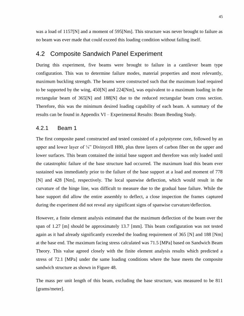
45
was a load of 1157[N] and a moment of 595[Nm]. This structure was never brought to failure as
no beam was ever made that could exceed this loading condition without failing itself.
4.2 Composite Sandwich Panel Experiment
During this experiment, five beams were brought to failure in a cantilever beam type
configuration. This was to determine failure modes, material properties and most relevantly,
maximum buckling strength. The beams were constructed such that the maximum load required
to be supported by the wing, 450[N] and 224[Nm], was equivalent to a maximum loading in the
rectangular beam of 365[N] and 188[N] due to the reduced rectangular beam cross section.
Therefore, this was the minimum desired loading capability of each beam. A summary of the
results can be found in Appendix VI – Experimental Results: Beam Bending Study.
4.2.1 Beam 1
The first composite panel constructed and tested consisted of a polystyrene core, followed by an
upper and lower layer of ¼” Divinycell H80, plus three layers of carbon fiber on the upper and
lower surfaces. This beam contained the initial base support and therefore was only loaded until
the catastrophic failure of the base structure had occurred. The maximum load this beam ever
sustained was immediately prior to the failure of the base support at a load and moment of 778
[N] and 428 [Nm], respectively. The local spanwise deflection, which would result in the
curvature of the hinge line, was difficult to measure due to the gradual base failure. While the
base support did allow the entire assembly to deflect, a close inspection the frames captured
during the experiment did not reveal any significant signs of spanwise curvature/deflection.
However, a finite element analysis estimated that the maximum deflection of the beam over the
span of 1.27 [m] should be approximately 13.7 [mm]. This beam configuration was not tested
again as it had already significantly exceeded the loading requirement of 365 [N] and 188 [Nm]
at the base end. The maximum facing stress calculated was 71.5 [MPa] based on Sandwich Beam
Theory. This value agreed closely with the finite element analysis results which predicted a
stress of 72.1 [MPa] under the same loading conditions where the base meets the composite
sandwich structure as shown in Figure 48.
The mass per unit length of this beam, excluding the base structure, was measured to be 811
[grams/meter].

46
Figure 48: CAD Analysis of Beam 1
4.2.2 Beam 2
The second composite panel constructed and tested consisted of a polystyrene core with three
layers of carbon fiber on the upper and lower surfaces. This beam, and all subsequent beams
tested, contained the base with added support walls. This beam was able to support a maximum
load and moment of 979 [N] and 504 [Nm], respectively, and the failure was due to local
buckling adjacent to the base joint as expected. This sudden failure is shown in Figure 49.
Figure 49: Failure of Beam 2
Start of
Buckling
Failure
Beam loaded in cantilever type configuration
Fixed steel bar Base Support Composite
Sandwich Panel
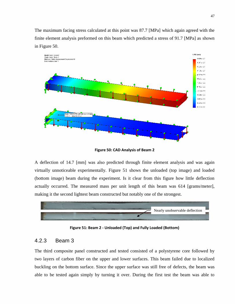
47
The maximum facing stress calculated at this point was 87.7 [MPa] which again agreed with the
finite element analysis preformed on this beam which predicted a stress of 91.7 [MPa] as shown
in Figure 50.
Figure 50: CAD Analysis of Beam 2
A deflection of 14.7 [mm] was also predicted through finite element analysis and was again
virtually unnoticeable experimentally. Figure 51 shows the unloaded (top image) and loaded
(bottom image) beam during the experiment. Is it clear from this figure how little deflection
actually occurred. The measured mass per unit length of this beam was 614 [grams/meter],
making it the second lightest beam constructed but notably one of the strongest.
Figure 51: Beam 2 - Unloaded (Top) and Fully Loaded (Bottom)
4.2.3 Beam 3
The third composite panel constructed and tested consisted of a polystyrene core followed by
two layers of carbon fiber on the upper and lower surfaces. This beam failed due to localized
buckling on the bottom surface. Since the upper surface was still free of defects, the beam was
able to be tested again simply by turning it over. During the first test the beam was able to
Nearly unobservable deflection
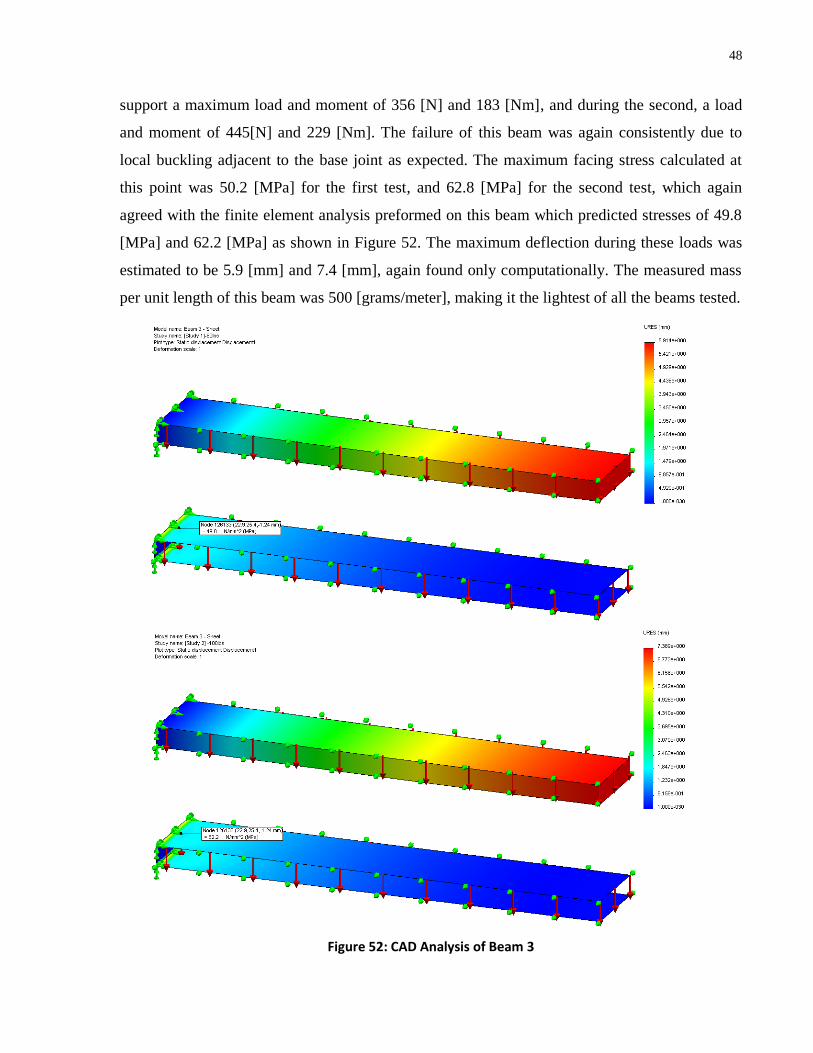
48
support a maximum load and moment of 356 [N] and 183 [Nm], and during the second, a load
and moment of 445[N] and 229 [Nm]. The failure of this beam was again consistently due to
local buckling adjacent to the base joint as expected. The maximum facing stress calculated at
this point was 50.2 [MPa] for the first test, and 62.8 [MPa] for the second test, which again
agreed with the finite element analysis preformed on this beam which predicted stresses of 49.8
[MPa] and 62.2 [MPa] as shown in Figure 52. The maximum deflection during these loads was
estimated to be 5.9 [mm] and 7.4 [mm], again found only computationally. The measured mass
per unit length of this beam was 500 [grams/meter], making it the lightest of all the beams tested.
Figure 52: CAD Analysis of Beam 3
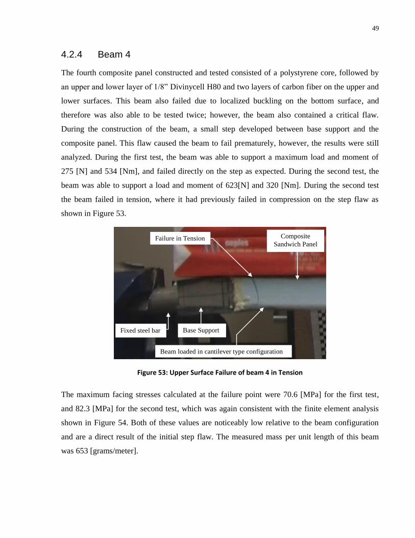
49
4.2.4 Beam 4
The fourth composite panel constructed and tested consisted of a polystyrene core, followed by
an upper and lower layer of 1/8” Divinycell H80 and two layers of carbon fiber on the upper and
lower surfaces. This beam also failed due to localized buckling on the bottom surface, and
therefore was also able to be tested twice; however, the beam also contained a critical flaw.
During the construction of the beam, a small step developed between base support and the
composite panel. This flaw caused the beam to fail prematurely, however, the results were still
analyzed. During the first test, the beam was able to support a maximum load and moment of
275 [N] and 534 [Nm], and failed directly on the step as expected. During the second test, the
beam was able to support a load and moment of 623[N] and 320 [Nm]. During the second test
the beam failed in tension, where it had previously failed in compression on the step flaw as
shown in Figure 53.
Figure 53: Upper Surface Failure of beam 4 in Tension
The maximum facing stresses calculated at the failure point were 70.6 [MPa] for the first test,
and 82.3 [MPa] for the second test, which was again consistent with the finite element analysis
shown in Figure 54. Both of these values are noticeably low relative to the beam configuration
and are a direct result of the initial step flaw. The measured mass per unit length of this beam
was 653 [grams/meter].
Failure in Tension
Beam loaded in cantilever type configuration
Fixed steel bar Base Support
Composite
Sandwich Panel
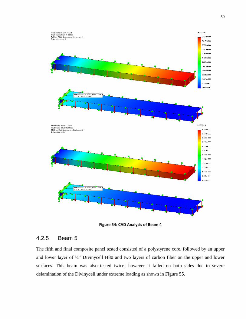
50
Figure 54: CAD Analysis of Beam 4
4.2.5 Beam 5
The fifth and final composite panel tested consisted of a polystyrene core, followed by an upper
and lower layer of ¼” Divinycell H80 and two layers of carbon fiber on the upper and lower
surfaces. This beam was also tested twice; however it failed on both sides due to severe
delamination of the Divinycell under extreme loading as shown in Figure 55.

51
Figure 55: Delamination Failure of Beam 5
During the first test the beam was able to support a maximum load and moment of 801 [N] and
412 [Nm] and during the second a load and moment of 979[N] and 504 [Nm]. The maximum
facing stresses calculated at this point were 96.9 [MPa] for the first test, and 118.4 [MPa] for the
second test, which again agreed with the finite element analysis preformed on this beam which
predicted stresses of 97.4 [MPa] and 119.1 [MPa], respectively, as shown in Figure 56.
Delamination of Divinycell
from polystyrene core
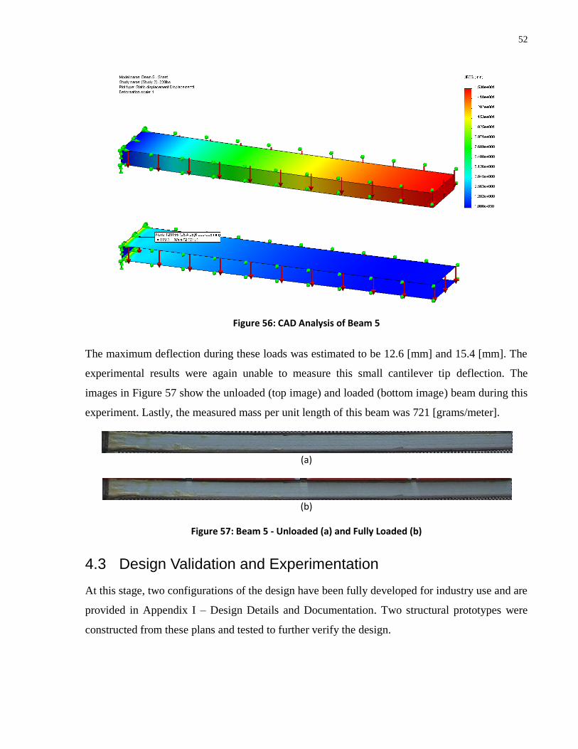
52
Figure 56: CAD Analysis of Beam 5
The maximum deflection during these loads was estimated to be 12.6 [mm] and 15.4 [mm]. The
experimental results were again unable to measure this small cantilever tip deflection. The
images in Figure 57 show the unloaded (top image) and loaded (bottom image) beam during this
experiment. Lastly, the measured mass per unit length of this beam was 721 [grams/meter].
(a)
(b)
Figure 57: Beam 5 - Unloaded (a) and Fully Loaded (b)
4.3 Design Validation and Experimentation
At this stage, two configurations of the design have been fully developed for industry use and are
provided in Appendix I – Design Details and Documentation. Two structural prototypes were
constructed from these plans and tested to further verify the design.
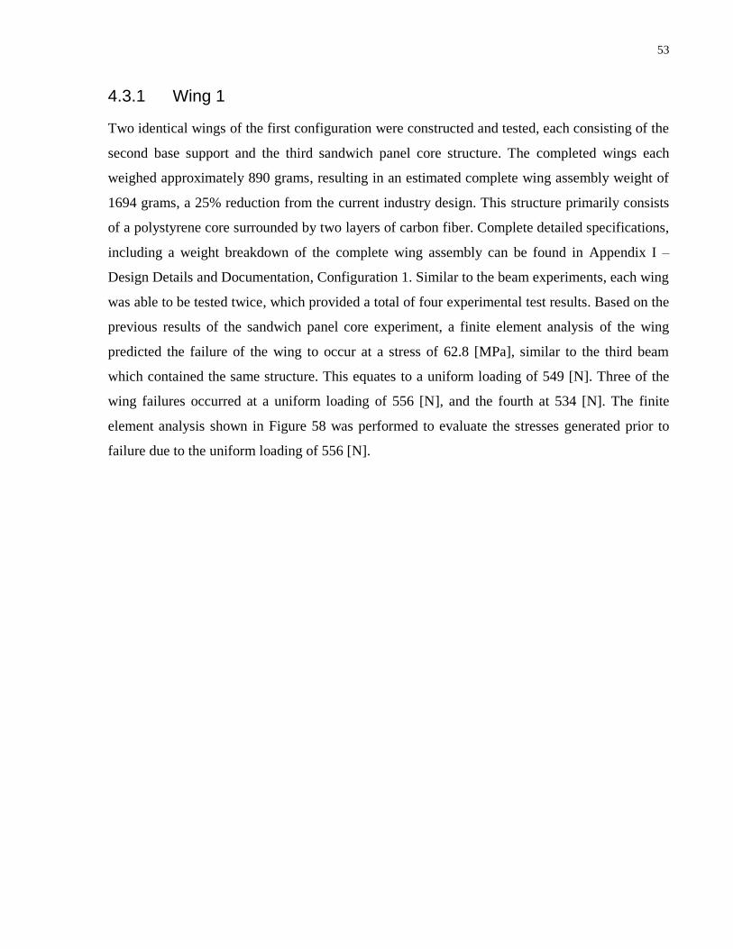
53
4.3.1 Wing 1
Two identical wings of the first configuration were constructed and tested, each consisting of the
second base support and the third sandwich panel core structure. The completed wings each
weighed approximately 890 grams, resulting in an estimated complete wing assembly weight of
1694 grams, a 25% reduction from the current industry design. This structure primarily consists
of a polystyrene core surrounded by two layers of carbon fiber. Complete detailed specifications,
including a weight breakdown of the complete wing assembly can be found in Appendix I –
Design Details and Documentation, Configuration 1. Similar to the beam experiments, each wing
was able to be tested twice, which provided a total of four experimental test results. Based on the
previous results of the sandwich panel core experiment, a finite element analysis of the wing
predicted the failure of the wing to occur at a stress of 62.8 [MPa], similar to the third beam
which contained the same structure. This equates to a uniform loading of 549 [N]. Three of the
wing failures occurred at a uniform loading of 556 [N], and the fourth at 534 [N]. The finite
element analysis shown in Figure 58 was performed to evaluate the stresses generated prior to
failure due to the uniform loading of 556 [N].
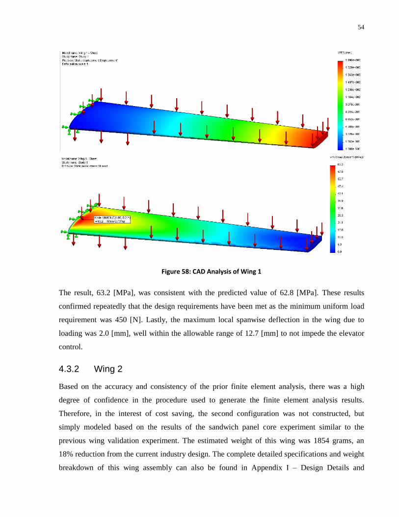
54
Figure 58: CAD Analysis of Wing 1
The result, 63.2 [MPa], was consistent with the predicted value of 62.8 [MPa]. These results
confirmed repeatedly that the design requirements have been met as the minimum uniform load
requirement was 450 [N]. Lastly, the maximum local spanwise deflection in the wing due to
loading was 2.0 [mm], well within the allowable range of 12.7 [mm] to not impede the elevator
control.
4.3.2 Wing 2
Based on the accuracy and consistency of the prior finite element analysis, there was a high
degree of confidence in the procedure used to generate the finite element analysis results.
Therefore, in the interest of cost saving, the second configuration was not constructed, but
simply modeled based on the results of the sandwich panel core experiment similar to the
previous wing validation experiment. The estimated weight of this wing was 1854 grams, an
18% reduction from the current industry design. The complete detailed specifications and weight
breakdown of this wing assembly can also be found in Appendix I – Design Details and

55
Documentation, Configuration 2. The finite element analysis of this wing configuration, shown
in Figure 59, predicted the failure of the wing to occur at a stress of 87.7 [MPa], similar to the
second beam, which equates to a uniform loading of 1165 [N] on the wing.
Figure 59: CAD Analysis of Wing 2
The maximum local spanwise deflection estimated at this load was 2.6 [mm], also still well
within the allowable range. Given that the minimum load to be uniformly supported was 450
[N], this design exceeds the design requirement by 159% and continues to provide a significant
level of weight reduction. Although the flutter characteristics of this wing were not calculated,
the increased stiffness of this configuration may also be beneficial as it much less prone to this
phenomenon.
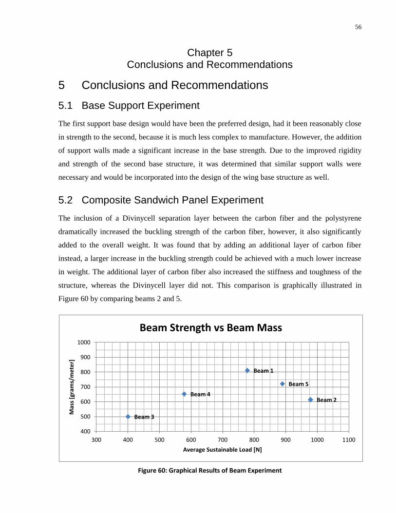
56
Chapter 5 Conclusions and Recommendations
5 Conclusions and Recommendations
5.1 Base Support Experiment
The first support base design would have been the preferred design, had it been reasonably close
in strength to the second, because it is much less complex to manufacture. However, the addition
of support walls made a significant increase in the base strength. Due to the improved rigidity
and strength of the second base structure, it was determined that similar support walls were
necessary and would be incorporated into the design of the wing base structure as well.
5.2 Composite Sandwich Panel Experiment
The inclusion of a Divinycell separation layer between the carbon fiber and the polystyrene
dramatically increased the buckling strength of the carbon fiber, however, it also significantly
added to the overall weight. It was found that by adding an additional layer of carbon fiber
instead, a larger increase in the buckling strength could be achieved with a much lower increase
in weight. The additional layer of carbon fiber also increased the stiffness and toughness of the
structure, whereas the Divinycell layer did not. This comparison is graphically illustrated in
Figure 60 by comparing beams 2 and 5.
Figure 60: Graphical Results of Beam Experiment
Beam 1
Beam 2
Beam 3
Beam 4
Beam 5
400
500
600
700
800
900
1000
300 400 500 600 700 800 900 1000 1100
Mas
s [g
ram
s/m
ete
r]
Average Sustainable Load [N]
Beam Strength vs Beam Mass

57
It is clear that beam 2, which contained three layers of carbon fiber, was both stronger and lighter
then beam 5, which contained two layers of carbon fiber along with a Divinycell separation
layer. One reason for this increased weight is the open cell structure of the Divinycell foam.
During the manufacturing process, the Divinycell foam absorbs excess resin from the carbon
fiber and cannot be removed. Even if this absorption could be avoided, the weight of the
Divinycell alone is still greater than the weight of an additional layer of carbon fiber.
While all the beams constructed exceeded the loading requirements, the most advantageous
structural properties were found in either beam 2 or beam 3. The third beam exceeded the
loading requirements by 9.8% on average, and was the lightest beam weighing only 500
[grams/meter]. The second beam weighed 614 [grams/meter], making it the second lightest.
However, it was the strongest and most rigid beam constructed, exceeding the loading
requirements by 168%. Due to the increased loading capacity, both core arrangements are being
proposed as varying configurations, each with unique advantages. The first arrangement provides
the lightest possible configuration which still meets the loading requirements. The second
arrangement still provides a significant weight reduction, while simultaneously providing a
dramatic increase in stiffness and loading capabilities, and therefore an increased safety factor in
the final design.
5.3 Design Validation and Experimentation
Based on the results of the prototype experimentation, two configurations of the design have
been developed and proposed, the first consisting of two layers of carbon fiber, and the second
consisting of three layers, both directly surrounding a polystyrene core. The first configuration
meets all the necessary design requirements with a weight reduction of 25% and a Factor of
Safety (FOS) of 1.85. The second configuration provides a weight reduction of 18.0%, however,
it also offers improved rigidity and an increased loading capacity of 159%. The Factor of Safety
(FOS) for this design becomes 3.88. Both designs incorporate the improved servo housing
assembly and provide sufficient rigidity to allow for complete motion of the elevator assembly
throughout all operational conditions. Both designs are fully capable of supporting an additional
winglet if necessary. There is high degree of confidence in these results as both wing
configurations were verified experimentally as well as by means of finite element analysis. The
beam and wing failures were both highly consistent with the finite element analysis estimates,

58
and as well, the failure mechanisms and maximum loads were highly consistent throughout the
experimentation, particularly notable given that they are composite structures.
5.4 Scientific contributions
The design developed and proven in this study provides the foundation for the development of a
truly spar-less wing design. This allows for a significant reduction in weight, cost, and
manufacturing time by eliminating all traditional rib and spar components. By utilizing current
methods of reducing surface delamination and component buckling, a single sandwich panel is
able to support the loads required for this component. A critical aspect of this design incorporates
the use an extremely rigid lightweight base structure located at the wing root. This base structure
replaces the spar in traditional rib and spar configuration and transfers the loads supported by the
wing skin to a single support channel where it fastens to the fuselage as a traditional wing would.
5.5 Future Recommendations
As a continuation of this research, it is recommended that further testing be performed to ensure
a safe and effective design. Primarily, a wind tunnel test of the wing structure should be
performed throughout all operation conditions and elevator positions. This should provide
conclusive results with regards to the structural integrity, flap control mechanism, and as well,
test for any possible signs of flutter. Even though composites generally have excellent fatigue
resistance properties, a fatigue test should be performed to ensure the design is fit for the extreme
cyclical loading it is expected to encounter. Lastly, it should be noted that the failure of a single
servo, particularly in a limit lockout position, could be catastrophic to the elevator control. This
scenario should be reviewed and the division of the elevator into independently controlled
partitions should be considered.
59
Bibliography
Azlin, M.A., C.F. Mat Taib, S. Kasolang, and F.H. Muhammad. CFD analysis of
winglets at low subsonic flow. World Congress on Engineering. (2011): 87-92.
Bruhn, E.F. Analysis and Design of Flight Vehicle Structures. Tri-State Offset Company,
1973. Print.
F., Warren. Mechanics of Flight. 1st ed. Wiley, 2009. Print.
Hollmann, Martin. Modern Aerodynamic Flutter Analysis. 1. 1. Monterey, California:
Aircraft Designs Inc., 1991. 159. Print.
Hull, D., and T.W. Clyne. An Introduction to Composite Materials. Second. New York,
NY: Press Syndicate of the University of Cambridge, 1996. Print.
Ji-Kui, Zhang, Li Zheng-neng, and Kou Chang-he. Structural Design of High Aspect
Ratio Composite Material Wing. Institute of Aircraft Design, Beijing. (2004).
Kong, C., H. Park, Y. Kim, and K. Kang. Structural Design on Wing of a Small Scale
WIG Vehicle with Carbon/Epoxy and Foam Sandwich Composite Structure. 16th
International Conference on Composite Materials. (2007).
Lee, Jong Woong, Cheol Won Kong, Se Won Eun, Jae Sung Park, Young Soon Jang,
Yeong Moo Yi, and Gwang-Rae Cho. Compression test of composte sandwich
panel. Key Engineering Materials. 348-349. (2007): 605-609.
Lee, Myoungkeon, Changmin Cho, and Seyong Jang. HALE UAV Composite Wing
Structure Design. Advanced Materials Research. 123-125. (2010): 105-109.
Long, D.U. Mechanical Properties and Structural Design of a Novel Composite Box for
High Aspect Ratio Wing. Journal of Thermoplastic Composite Materials. 24. no.
11 (2011): 819-836.
60
Plantema, F, J., 1966, Sandwich Construction: The Bending and Buckling of Sandwich
Beams, Plates, and Shells, Jon Wiley and Sons, New York.
Pugsley, A. A Simplified Theory of Wing Flutter. Aeronautical Research Committee.
(1956): 1-11. Print.
Scott, Jeff. Ground Effect and WIG Vehicles. aerospaceweb.org. aerospaceweb.org, 29
Jun 2003. Web. 25 Oct 2010.
Shan, B, and A Pelegri. Approximate Analysis of the Buckling Behavior of Composites
with Delamination. Journal of Composite Materials. 37. no. 8 (2003): 673-686.
Sullivan, R. Warsi, Y. Hwang, M. Rais-Rohani, and T. Lacy. Structural Analysis and
Testing of and Ultralight Unmanned-Aerial-Vehicle Carbon-Composite Wing.
Journal of Aircraft. 46. no. 3 (2009): 814-821.
Zenkert, D. An Introduction to Sandwich Construction, Engineering Materials Advisory
Services Ltd, UK., 1995. Print.

61
Appendix I – Design Details and Documentation
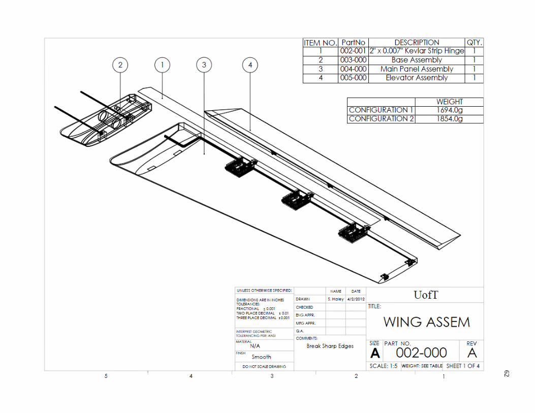
62
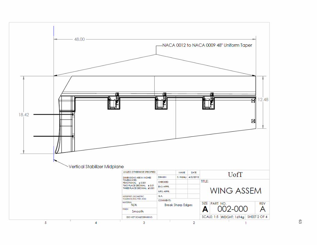
63

64
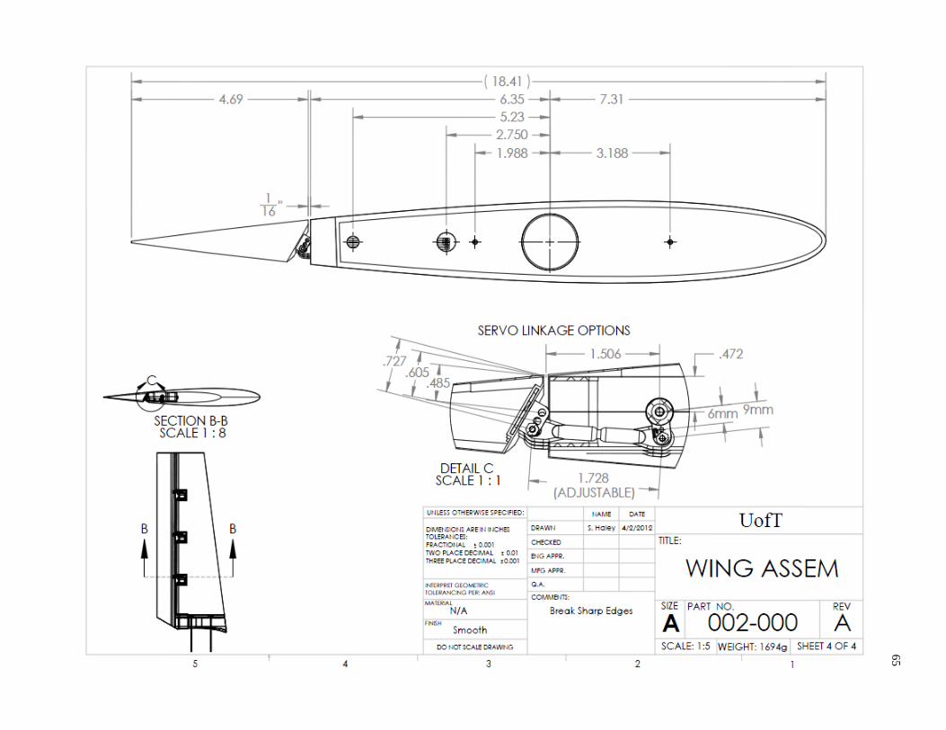
65

66
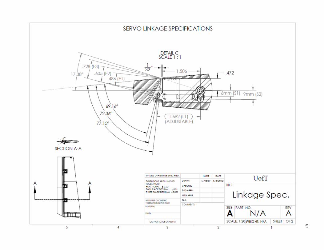
67

68
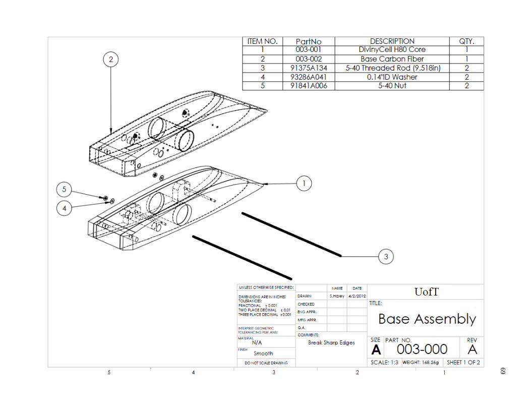
69

70

71
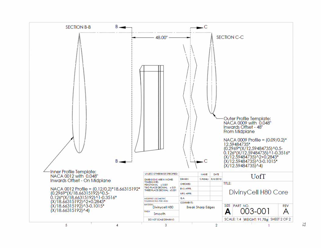
72

73

74

75
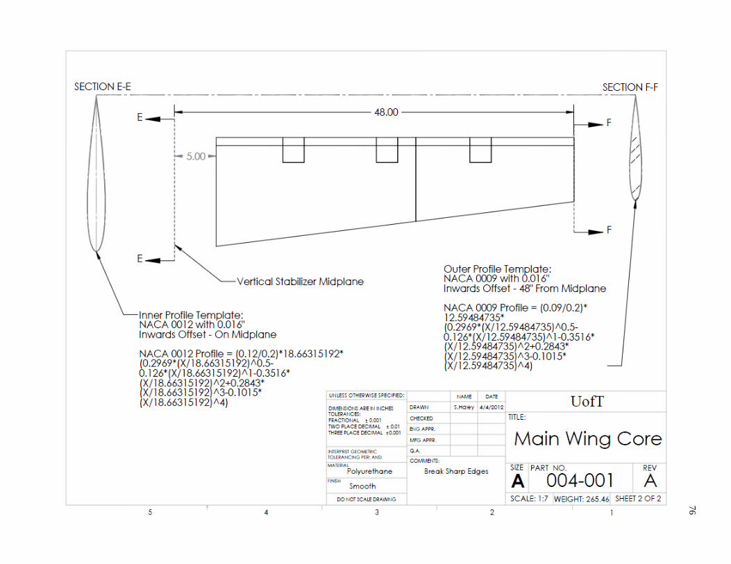
76
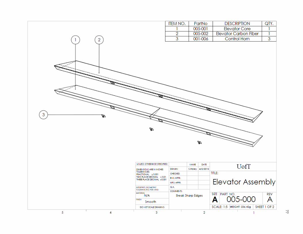
77

78
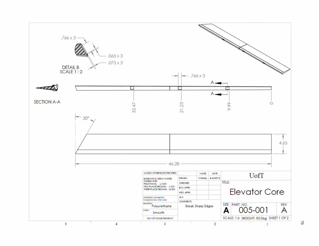
79

80
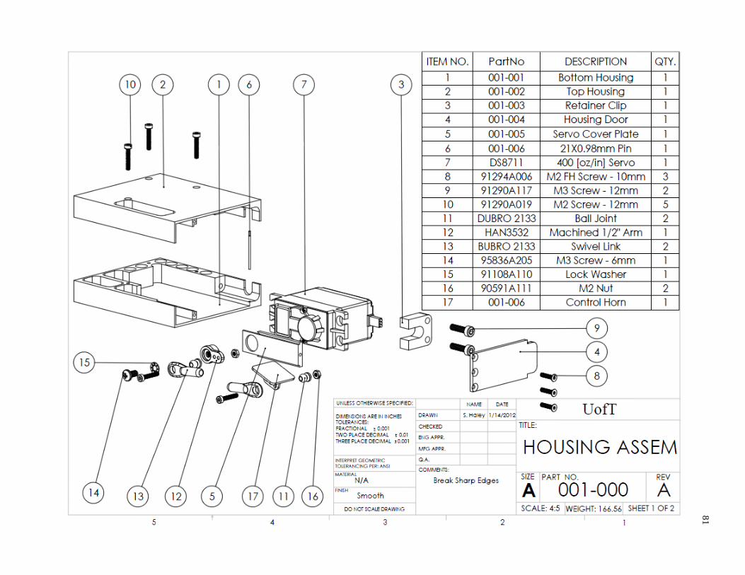
81

82

83

84
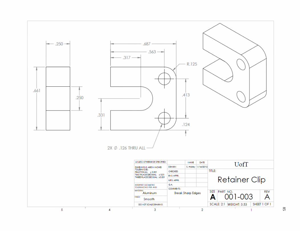
85

86
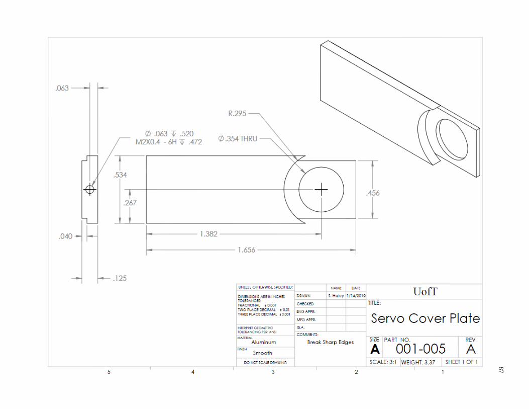
87
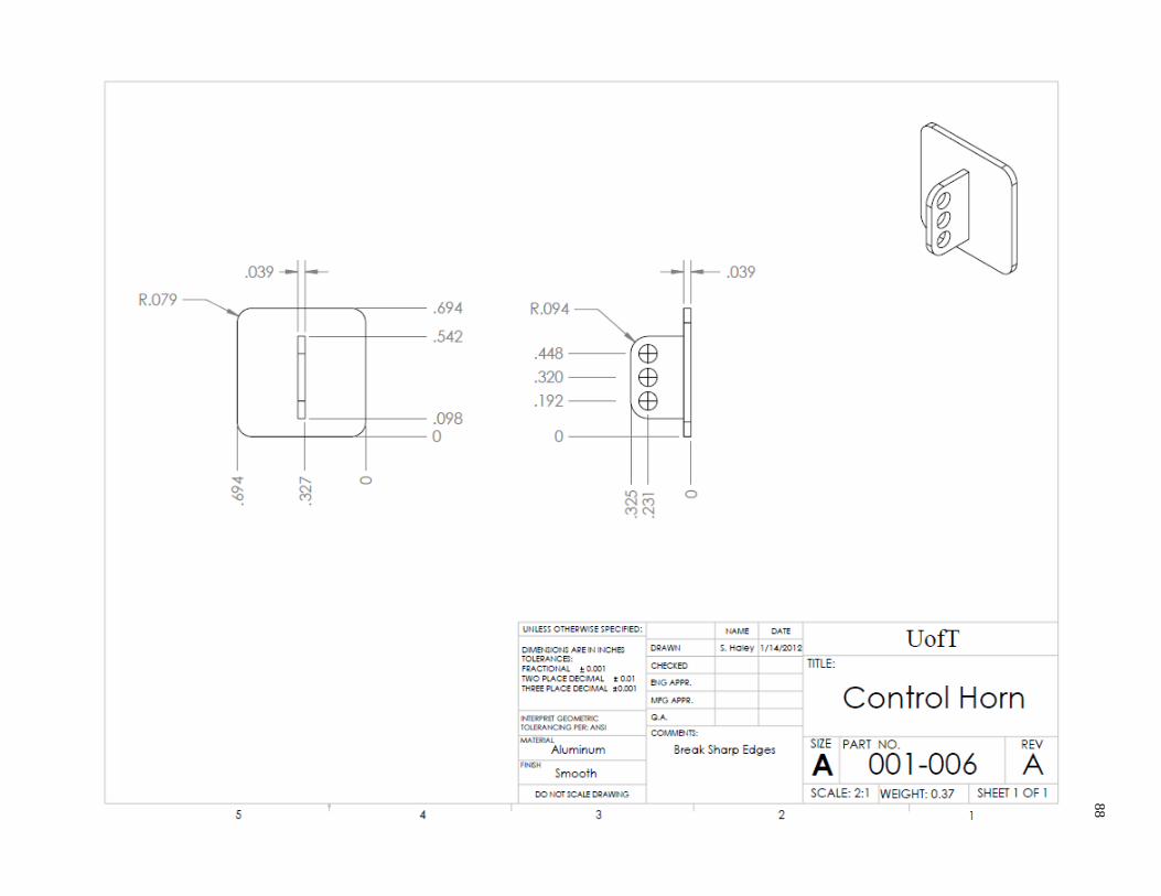
88
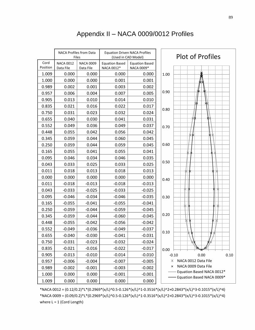
89
Appendix II – NACA 0009/0012 Profiles
NACA Profiles from Data Files
Equation Driven NACA Profiles (Used in CAD Model)
Cord Position
NACA 0012 Data File
NACA 0009 Data File
Equation Based NACA 0012*
Equation Based NACA 0009*
1.009 0.000 0.000 0.000 0.000 1.000 0.000 0.000 0.001 0.001 0.989 0.002 0.001 0.003 0.002 0.957 0.006 0.004 0.007 0.005 0.905 0.013 0.010 0.014 0.010 0.835 0.021 0.016 0.022 0.017 0.750 0.031 0.023 0.032 0.024 0.655 0.040 0.030 0.041 0.031 0.552 0.049 0.036 0.049 0.037 0.448 0.055 0.042 0.056 0.042 0.345 0.059 0.044 0.060 0.045 0.250 0.059 0.044 0.059 0.045 0.165 0.055 0.041 0.055 0.041 0.095 0.046 0.034 0.046 0.035 0.043 0.033 0.025 0.033 0.025 0.011 0.018 0.013 0.018 0.013 0.000 0.000 0.000 0.000 0.000 0.011 -0.018 -0.013 -0.018 -0.013 0.043 -0.033 -0.025 -0.033 -0.025 0.095 -0.046 -0.034 -0.046 -0.035 0.165 -0.055 -0.041 -0.055 -0.041 0.250 -0.059 -0.044 -0.059 -0.045 0.345 -0.059 -0.044 -0.060 -0.045 0.448 -0.055 -0.042 -0.056 -0.042 0.552 -0.049 -0.036 -0.049 -0.037 0.655 -0.040 -0.030 -0.041 -0.031 0.750 -0.031 -0.023 -0.032 -0.024 0.835 -0.021 -0.016 -0.022 -0.017 0.905 -0.013 -0.010 -0.014 -0.010 0.957 -0.006 -0.004 -0.007 -0.005 0.989 -0.002 -0.001 -0.003 -0.002 1.000 0.000 0.000 -0.001 -0.001 1.009 0.000 0.000 0.000 0.000 *NACA 0012 = (0.12/0.2)*L*(0.2969*(x/L)^0.5-0.126*(x/L)^1-0.3516*(x/L)^2+0.2843*(x/L)^3-0.1015*(x/L)^4)
*NACA 0009 = (0.09/0.2)*L*(0.2969*(x/L)^0.5-0.126*(x/L)^1-0.3516*(x/L)^2+0.2843*(x/L)^3-0.1015*(x/L)^4)
where L = 1 (Cord Length)
0.00
0.10
0.20
0.30
0.40
0.50
0.60
0.70
0.80
0.90
1.00
-0.10 0.00 0.10
Plot of Profiles
NACA 0012 Data File
NACA 0009 Data File
Equation Based NACA 0012*
Equation Based NACA 0009*
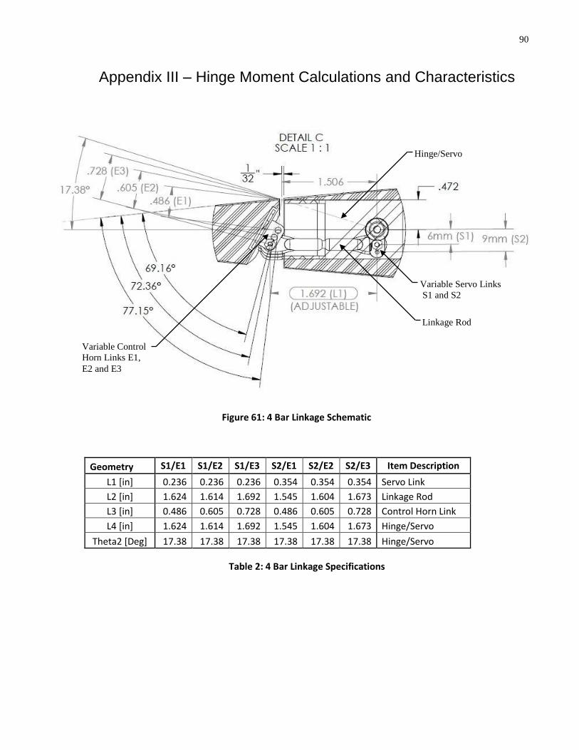
90
Appendix III – Hinge Moment Calculations and Characteristics
Geometry S1/E1 S1/E2 S1/E3 S2/E1 S2/E2 S2/E3 Item Description
L1 [in] 0.236 0.236 0.236 0.354 0.354 0.354 Servo Link
L2 [in] 1.624 1.614 1.692 1.545 1.604 1.673 Linkage Rod
L3 [in] 0.486 0.605 0.728 0.486 0.605 0.728 Control Horn Link
L4 [in] 1.624 1.614 1.692 1.545 1.604 1.673 Hinge/Servo
Theta2 [Deg] 17.38 17.38 17.38 17.38 17.38 17.38 Hinge/Servo
Table 2: 4 Bar Linkage Specifications
Figure 61: 4 Bar Linkage Schematic
Variable Servo Links
S1 and S2
Variable Control
Horn Links E1,
E2 and E3
Linkage Rod
Hinge/Servo
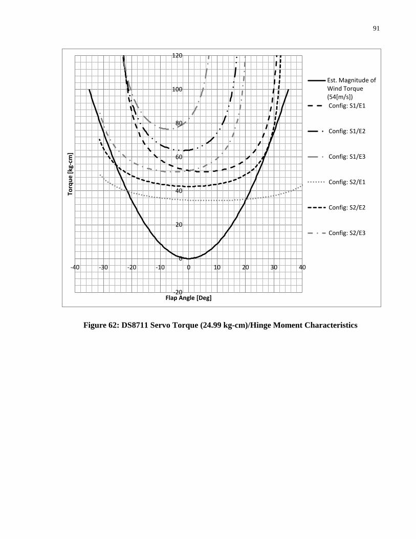
91
Figure 62: DS8711 Servo Torque (24.99 kg-cm)/Hinge Moment Characteristics
-20
0
20
40
60
80
100
120
-40 -30 -20 -10 0 10 20 30 40
Torq
ue
[kg
-cm
]
Flap Angle [Deg]
Est. Magnitude of Wind Torque (54[m/s])
Config: S1/E1
Config: S1/E2
Config: S1/E3
Config: S2/E1
Config: S2/E2
Config: S2/E3
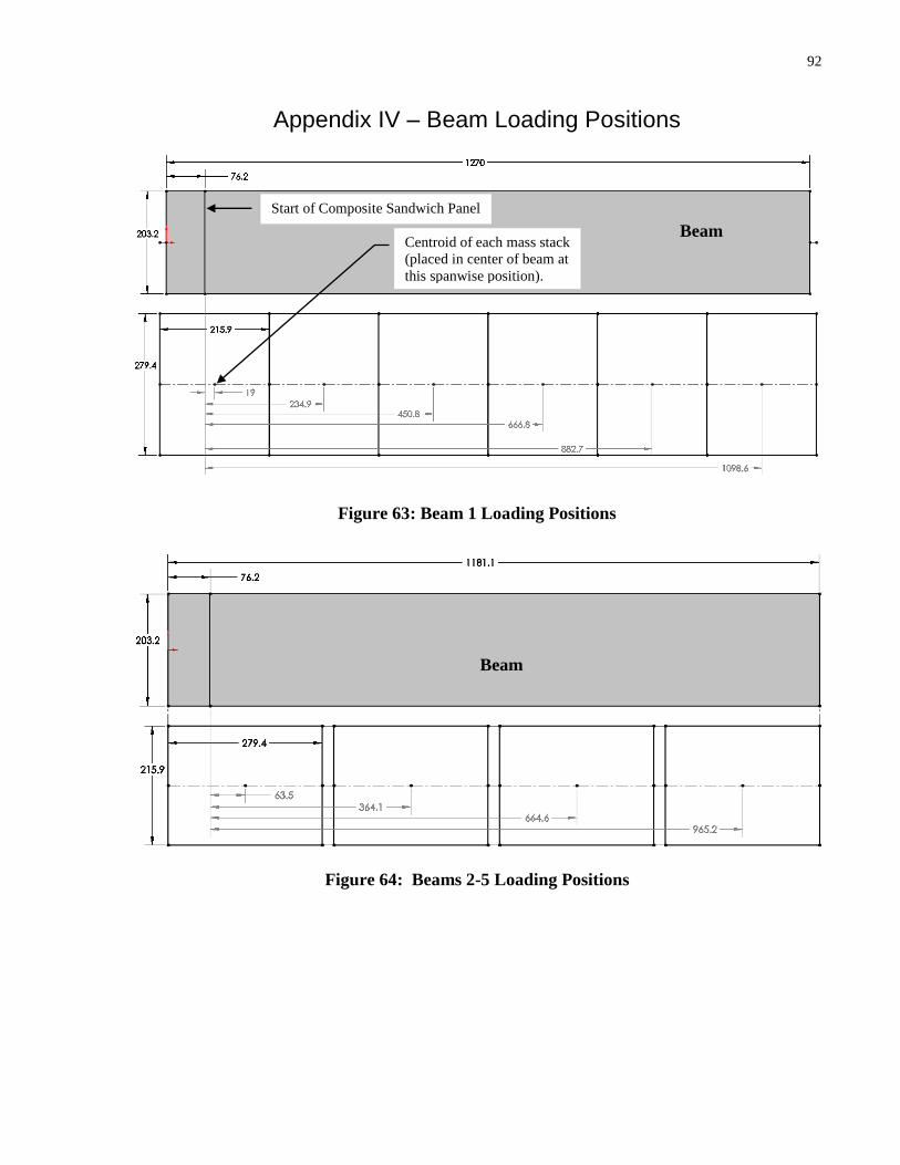
92
Appendix IV – Beam Loading Positions
Figure 63: Beam 1 Loading Positions
Figure 64: Beams 2-5 Loading Positions
Beam
Beam
Centroid of each mass stack
(placed in center of beam at
this spanwise position).
Start of Composite Sandwich Panel
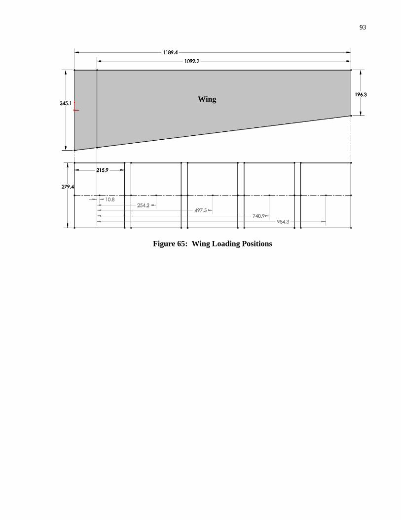
93
Figure 65: Wing Loading Positions
Wing

94
Appendix V – Example of Accelerometer Input / Output
Figure 66: Accelerometer Input Vibration Example
Figure 67: Output after Separation of Bending and Torsional Vibration
-0.15
-0.1
-0.05
0
0.05
0.1
0.15
0 0.25 0.5 0.75 1 1.25 1.5
Dis
pla
cem
en
t [m
]
Time [s]
Accelerometer 1
Accelerometer 2
-5.00
-4.00
-3.00
-2.00
-1.00
0.00
1.00
2.00
3.00
4.00
5.00
-0.15
-0.10
-0.05
0.00
0.05
0.10
0.15
0 0.25 0.5 0.75 1 1.25 1.5
An
gle
[ra
d]
Dis
pla
cem
en
t [m
]
Time [s]
Bending (Est)
Bending (Real)
Torsion (Est)
Torsion (Real)

95
Appendix VI – Experimental Results: Beam Bending Study
Beam 1 Experimental Results
Trial 1 – Unloaded Beam
Total Beam Mass: 1150g
Mass/Length: 811 [g/m]
Trial 1 – Maximum Loading Before Failure
Maximum Load: 778 [N]
Maximum Moment: 423 [N-m]
Figure 68: Beam 1 Cross-Section
Fixed steel bar representing the support spar
Beam loaded in Cantilever type configuration

96
Beam 2 Experimental Results
Trial 1 – Unloaded
Total Beam Mass: 879g
Mass/Length: 614 [g/m]
Trial 1 – Maximum Loading Before Failure
Maximum Load: 979 [N]
Maximum Moment: 504 [N-m]
Figure 69: Beam 2 Cross-Section

97
Beam 3 Experimental Results
Trial 1 – Unloaded
Total Beam Mass: 767.4g
Mass/Length: 500 [g/m]
Trial 1 – Maximum Loading Before Failure
Maximum Load: 356 [N]
Maximum Moment: 183 [N-m]
Trial 2 – Unloaded
Beam Mass: 767.4g
Mass/Length: 500 [g/m]
Not Captured
Trial 2 – Maximum Loading Before Failure
Max Load: 445 [N]
Maximum Moment: 229 [N-m]
Not Captured
Figure 70: Beam 3 Cross-Section
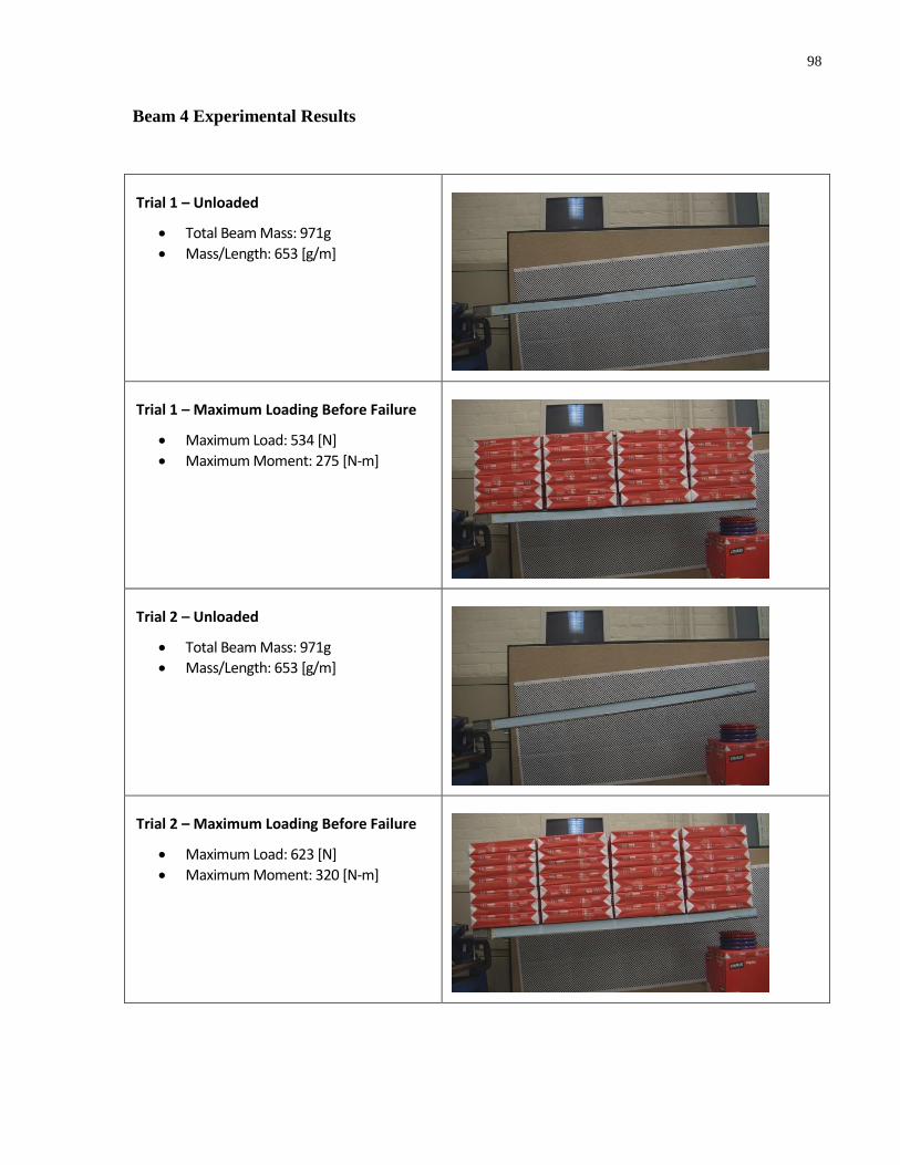
98
Beam 4 Experimental Results
Trial 1 – Unloaded
Total Beam Mass: 971g
Mass/Length: 653 [g/m]
Trial 1 – Maximum Loading Before Failure
Maximum Load: 534 [N]
Maximum Moment: 275 [N-m]
Trial 2 – Unloaded
Total Beam Mass: 971g
Mass/Length: 653 [g/m]
Trial 2 – Maximum Loading Before Failure
Maximum Load: 623 [N]
Maximum Moment: 320 [N-m]

99
Figure 71: Beam 4 Cross-Section
Beam 5 Experimental Results
Trial 1 – Unloaded
Beam Mass: 1039g
Mass/Length: 721 [g/m]
Trial 1 – Maximum Loading Before Failure
Maximum Load: 801 [N]
Maximum Moment: 504 [N-m]
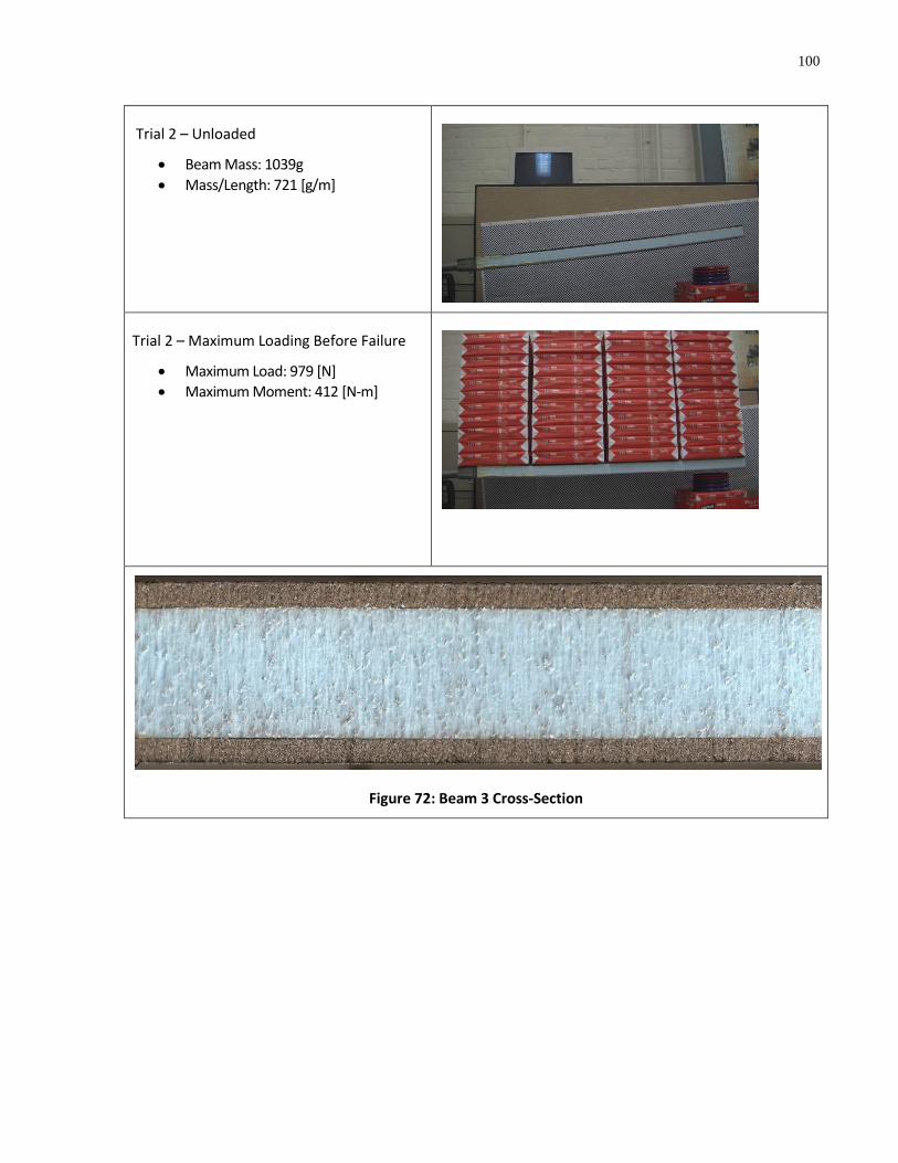
100
Trial 2 – Unloaded
Beam Mass: 1039g
Mass/Length: 721 [g/m]
Trial 2 – Maximum Loading Before Failure
Maximum Load: 979 [N]
Maximum Moment: 412 [N-m]
Figure 72: Beam 3 Cross-Section

10
1
Summary of Experimental Results
Beam Specifications
Beam Dimensions [mm]
Layer Thicknesses [mm]
Beam Description Failure Mode
Width Length Height
CF Div Foam Div CF Total
1 3 Layer CF + 6.7mm Div. Base Support Failure
203 1270 49.0
0.61 6.7 34.3 6.7 0.61 49.0
2 3 Layer CF CF Buckling (Perfectly)
203 1181 51.7
0.56 0.0 50.6 0.0 0.56 51.7
3 2 Layer CF all round CF Buckling (Perfectly)
203 1181 51.2
0.36 0.0 50.4 0.0 0.36 51.2
3b* 2 Layer CF all round CF Buckling (Perfectly)
203 1181 51.2
0.36 0.0 50.4 0.0 0.36 51.2
4 2 Layer CF + 3.2mm Div. CF Buckling (On Joint Flaw)
203 1181 48.0
0.41 6.7 37.2 3.2 0.41 48.0
4b* 2 Layer CF + 6.7mm Div. In tension (Due to Trial 1)
203 1181 48.0
0.41 6.7 37.2 3.2 0.41 48.0
5 2 Layer CF + 6.7mm Div. Core Buckling (Delamination)
203 1181 52.3
0.41 6.7 38.0 6.7 0.41 52.3
5b* 2 Layer CF + 6.7mm Div. Core Buckling (Delamination)
203 1181 52.3
0.41 6.7 38.0 6.7 0.41 52.3
*recycled from previous test
Masses [g]
Sectional Properties
Stress Analysis (Max Values)
Base Block Foam Div CF Resin Glue Total
Mass
[g] Length [mm]
Failure
[kgs]
Moment
[Nm]
Force
[N]
Facing Stress
[MPa]
Core Shear
[KPa]
155 231 265 332 156 16 1155
783 965
79.4 423 778 71.5 160.4
184 316 0 305 75 0 879
624 1016
99.8 504 979 87.7 190.5
184 315 0 194 74 0 767
508 1016
36.3 183 356 50.2 69.4
184 315 0 194 74 0 767
508 1016
45.4 229 445 62.8 86.8
220 232 181 207 107 25 971
663 1016
54.4 275 534 70.5 111.4
220 232 181 207 107 25 971
663 1016
63.5 320 623 82.3 130.0
227 237 245 203 110 16 1039
733 1016
81.6 412 801 96.8 153.0
227 237 245 203 110 16 1039
733 1016
99.8 504 979 118.4 187.0
CAD Analysis (Max Values)
Disp. [mm] Facing Stress [MPa]
13.7 72.1
14.74 91.7
5.914 49.8
7.389 62.2
9.324 72.3
10.88 84.3
12.58 97.4
15.38 119.1
Table 3: Beam Study Results
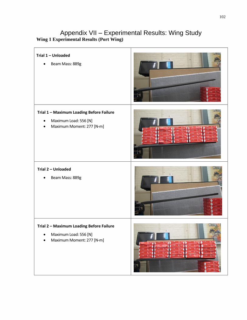
102
Appendix VII – Experimental Results: Wing Study Wing 1 Experimental Results (Port Wing)
Trial 1 – Unloaded
Beam Mass: 889g
Trial 1 – Maximum Loading Before Failure
Maximum Load: 556 [N]
Maximum Moment: 277 [N-m]
Trial 2 – Unloaded
Beam Mass: 889g
Trial 2 – Maximum Loading Before Failure
Maximum Load: 556 [N]
Maximum Moment: 277 [N-m]
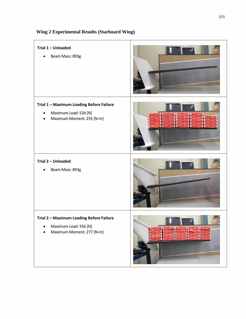
103
Wing 2 Experimental Results (Starboard Wing)
Trial 1 – Unloaded
Beam Mass: 893g
Trial 1 – Maximum Loading Before Failure
Maximum Load: 534 [N]
Maximum Moment: 255 [N-m]
Trial 2 – Unloaded
Beam Mass: 893g
Trial 2 – Maximum Loading Before Failure
Maximum Load: 556 [N]
Maximum Moment: 277 [N-m]
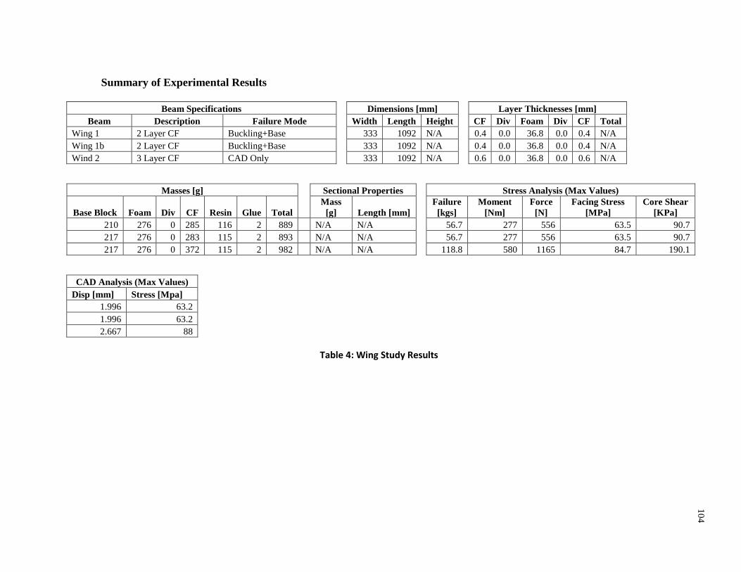
10
4
Summary of Experimental Results
Beam Specifications
Dimensions [mm]
Layer Thicknesses [mm]
Beam Description Failure Mode
Width Length Height
CF Div Foam Div CF Total
Wing 1 2 Layer CF Buckling+Base
333 1092 N/A
0.4 0.0 36.8 0.0 0.4 N/A
Wing 1b 2 Layer CF Buckling+Base
333 1092 N/A
0.4 0.0 36.8 0.0 0.4 N/A
Wind 2 3 Layer CF CAD Only
333 1092 N/A
0.6 0.0 36.8 0.0 0.6 N/A
Masses [g]
Sectional Properties
Stress Analysis (Max Values)
Base Block Foam Div CF Resin Glue Total
Mass
[g] Length [mm]
Failure
[kgs]
Moment
[Nm]
Force
[N]
Facing Stress
[MPa]
Core Shear
[KPa]
210 276 0 285 116 2 889 N/A N/A
56.7 277 556 63.5 90.7
217 276 0 283 115 2 893 N/A N/A
56.7 277 556 63.5 90.7
217 276 0 372 115 2 982 N/A N/A
118.8 580 1165 84.7 190.1
CAD Analysis (Max Values)
Disp [mm] Stress [Mpa]
1.996 63.2
1.996 63.2
2.667 88
Table 4: Wing Study Results
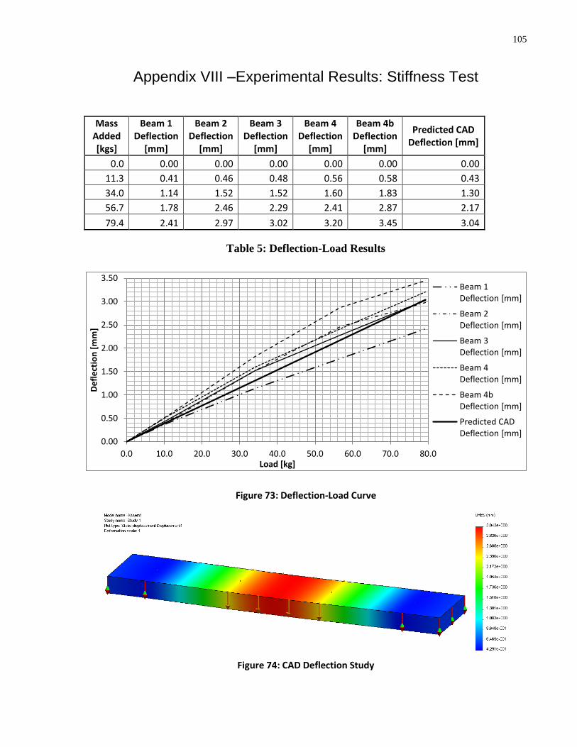
105
105
Appendix VIII –Experimental Results: Stiffness Test
Mass Added [kgs]
Beam 1 Deflection
[mm]
Beam 2 Deflection
[mm]
Beam 3 Deflection
[mm]
Beam 4 Deflection
[mm]
Beam 4b Deflection
[mm]
Predicted CAD Deflection [mm]
0.0 0.00 0.00 0.00 0.00 0.00 0.00
11.3 0.41 0.46 0.48 0.56 0.58 0.43
34.0 1.14 1.52 1.52 1.60 1.83 1.30
56.7 1.78 2.46 2.29 2.41 2.87 2.17
79.4 2.41 2.97 3.02 3.20 3.45 3.04
Table 5: Deflection-Load Results
Figure 73: Deflection-Load Curve
Figure 74: CAD Deflection Study
0.00
0.50
1.00
1.50
2.00
2.50
3.00
3.50
0.0 10.0 20.0 30.0 40.0 50.0 60.0 70.0 80.0
De
fle
ctio
n [
mm
]
Load [kg]
Beam 1 Deflection [mm]
Beam 2 Deflection [mm]
Beam 3 Deflection [mm]
Beam 4 Deflection [mm]
Beam 4b Deflection [mm]
Predicted CAD Deflection [mm]
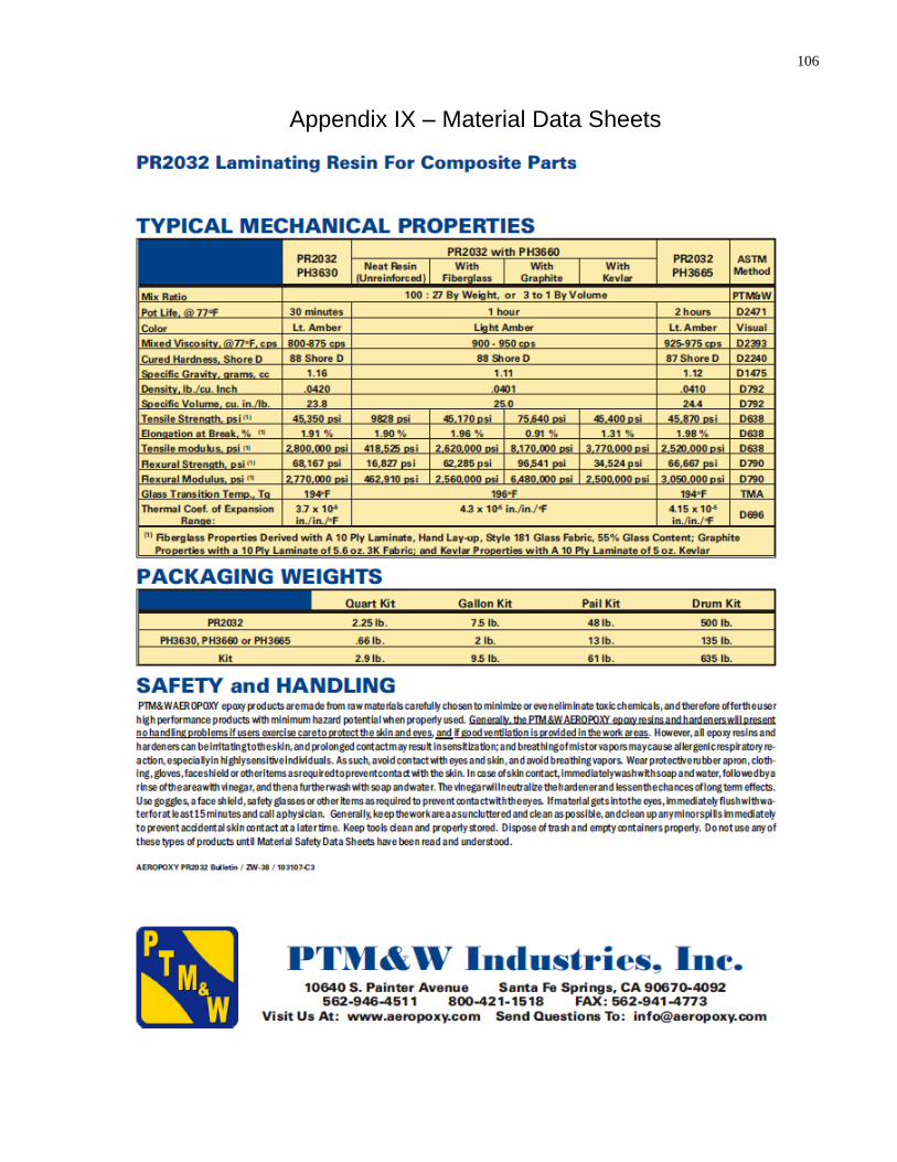
106
106
Appendix IX – Material Data Sheets

107
107
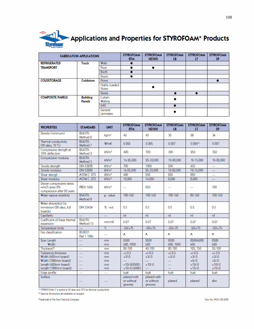
108
108
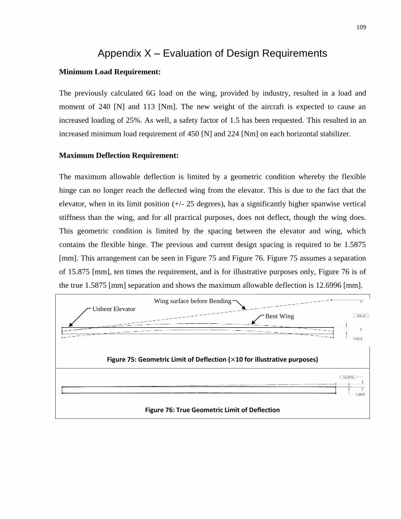
109
109
Appendix X – Evaluation of Design Requirements
Minimum Load Requirement:
The previously calculated 6G load on the wing, provided by industry, resulted in a load and
moment of 240 [N] and 113 [Nm]. The new weight of the aircraft is expected to cause an
increased loading of 25%. As well, a safety factor of 1.5 has been requested. This resulted in an
increased minimum load requirement of 450 [N] and 224 [Nm] on each horizontal stabilizer.
Maximum Deflection Requirement:
The maximum allowable deflection is limited by a geometric condition whereby the flexible
hinge can no longer reach the deflected wing from the elevator. This is due to the fact that the
elevator, when in its limit position (+/- 25 degrees), has a significantly higher spanwise vertical
stiffness than the wing, and for all practical purposes, does not deflect, though the wing does.
This geometric condition is limited by the spacing between the elevator and wing, which
contains the flexible hinge. The previous and current design spacing is required to be 1.5875
[mm]. This arrangement can be seen in Figure 75 and Figure 76. Figure 75 assumes a separation
of 15.875 [mm], ten times the requirement, and is for illustrative purposes only, Figure 76 is of
the true 1.5875 [mm] separation and shows the maximum allowable deflection is 12.6996 [mm].
Figure 75: Geometric Limit of Deflection ( 10 for illustrative purposes)
Figure 76: True Geometric Limit of Deflection
Unbent Elevator Bent Wing
Wing surface before Bending