development of dual torch welding system for pipeline and its on
TRANSCRIPT
154Copyright © 2015 JFE Steel Corporation. All Rights Reserved.
Abstract:Dual torch welding system was developed for girth
welding to improve welding efficiency on the pipeline construction. This is the first application of girth weld-ing to pipeline construction in Japan, reducing the weld-ing time by half at field, and enabling high quality girth welding. The developed dual torch welding system is introduced and the effect of application is reported.
1. Introduction
On-site welding of pipelines has conventionally depended on experienced welders who possess a high level of skill, as it is outdoor work, groove accuracy is difficult to secure, and welding is performed by all-position one-side penetration welding. However, in recent years, shortages of skilled welders and the advanced age of available personnel have become serious problems. In response, automation of pipeline welding has been pro-moted. The main-force MAX-II automatic welding sys-tem for pipelines, which was developed by JFE Engi-neering, has been used to weld approximately 65 000 joints to date, and has earned a high evaluation from customers.
In recent pipeline construction work (high pressure pipelines) in Japan, the number of projects involving welding in non-open cut shielded tunnels and pipe cas-ing welding has increased. Since welding efficiency determines total project efficiency to a greater extent than in the past, higher welding efficiency is now demanded. This paper presents an outline of the devel-
opment of a dual torch welding technology for the pur-pose of achieving higher efficiency in automatic weld-ing, and the results of its on-site application.
2. TransitionofAutomaticWeldingTechnologiesforPipelinesJFE Engineering began on-site introduction of auto-
matic welding systems for pipelines in 1970, and has continued to develop automatic welding systems with the aim of improving weld quality and ending depen-dence on the competence of operators. Table1 shows the transition of the automation level. MAX, which was an automation level I technology, was an automatic welding system in which each of the operations was mechanized while retaining the feel of manual welding. This technology made an important contribution to eas-ing resistance to automatic welding in the field. As a
† Originally published in JFE GIHO No. 34 (Aug. 2014), p. 104–108
*2 Manager, Welding Gr., Pipeline Engineering Dept., JFE Engineering
*1 Deputy Manager, Pipeline Engineering Dept., JFE Engineering
*3 Pipeline Engineering Dept., JFE Engineering
JFETECHNICALREPORTNo.20(Mar.2015)
Development of Dual Torch Welding System for Pipeline and Its On-Site Application†
SUGIURA Kazuki*1 KATSUKI Makoto*2 YANO Yoshiaki*3
Table 1 Transition of welding automation level
Category Level I II III
(1) Mechanization of each operation
(2) Pre-set of welding conditions
(3) Sequence control
(4) Seam tracking control
(5) Adaptive control
Automatic welding system of the JFE Engineering Group
MAX From 1970
mini-MAX From 1987
MAX-II From 1987
: Affained : Unaffained
JFETECHNICALREPORTNo.20(Mar.2015) 155
Development of Dual Torch Welding System for Pipeline and Its On-Site Application
level II technology, mini-MAX is an automatic welding system for small-diameter pipes, and realizes presetting of welding conditions and automatic sequence control of the welding operation. The level III technology MAX-II achieves automation of vertical movement of the torch and seam tracking. MAX-II has been improved repeat-edly to date and is now JFE Engineering’s leading auto-matic welding system for pipelines.
3. DualTorchWeldingSystem
3.1 Outline
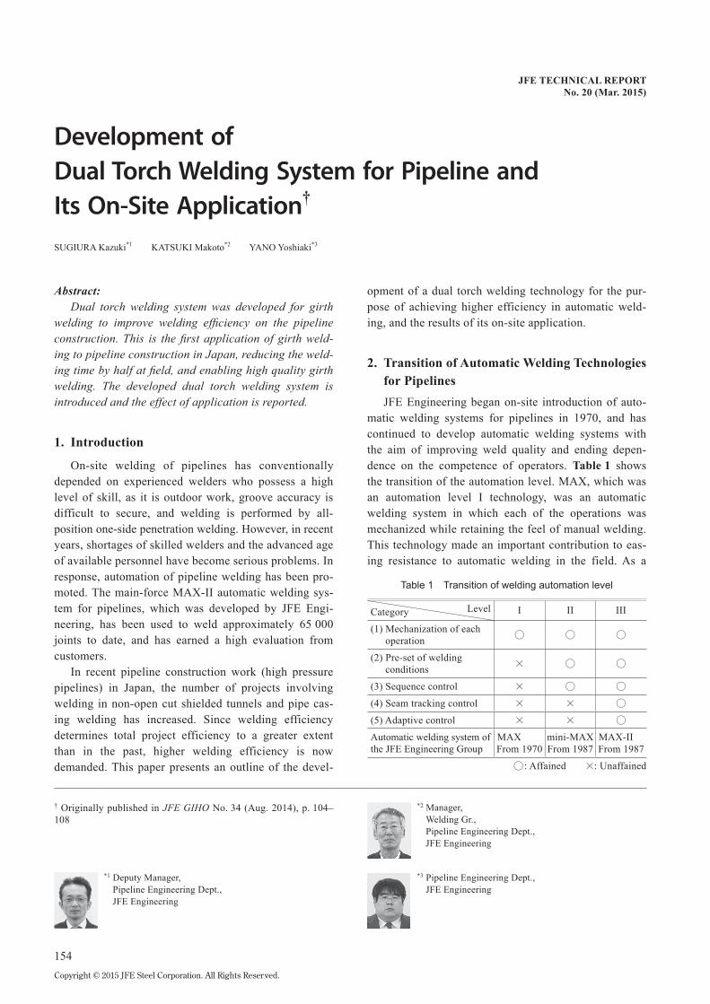
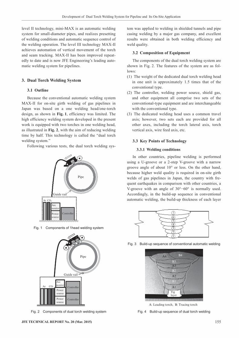
Because the conventional automatic welding system MAX-II for on-site girth welding of gas pipelines in Japan was based on a one welding head/one-torch design, as shown in Fig.1, efficiency was limited. The high efficiency welding system developed in the present work is equipped with two torches in one welding head, as illustrated in Fig.2, with the aim of reducing welding time by half. This technology is called the “dual torch welding system.”
Following various tests, the dual torch welding sys-
tem was applied to welding in shielded tunnels and pipe casing welding by a major gas company, and excellent results were obtained in both welding efficiency and weld quality.
3.2 CompositionofEquipment
The components of the dual torch welding system are shown in Fig. 2. The features of the system are as fol-lows:(1) The weight of the dedicated dual torch welding head
in one unit is approximately 1.5 times that of the conventional type.
(2) The controller, welding power source, shield gas, and other equipment all comprise two sets of the conventional-type equipment and are interchangeable with the conventional type.
(3) The dedicated welding head uses a common travel axis; however, two sets each are provided for all other axes, including the torch lateral axis, torch vertical axis, wire feed axis, etc.
3.3 KeyPointsofTechnology
3.3.1Weldingconditions
In other countries, pipeline welding is performed using a U-groove or a 2-step V-groove with a narrow groove angle of about 10° or less. On the other hand, because higher weld quality is required in on-site girth welds of gas pipelines in Japan, the country with fre-quent earthquakes in comparison with other countries, a V-groove with an angle of 30°−60° is normally used. Accordingly, in the build-up sequence in conventional automatic welding, the build-up thickness of each layer
Fig. 1 Components of 1head welding system
Fig. 2 Components of dual torch welding system
Fig. 3 Build-up sequence of conventional automatic welding
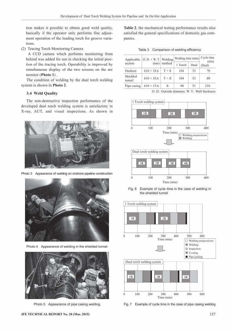
Fig. 4 Build-up sequence of dual torch welding

156 JFETECHNICALREPORTNo.20(Mar.2015)
Development of Dual Torch Welding System for Pipeline and Its On-Site Application
does not change greatly, as shown in in Fig.3 (wall thickness: 17.6 mm). The optimum welding speed is also different in each layer, and the order of the welding speed is generally 1>2>3>4>5>6>7.
With dual torches, it is necessary to perform welding of two passes at the same speed. Therefore, 2-pass simultaneous welding conditions were established by incorporating a wealth of data on welding conditions in a database, and innovations were also made in the build-up method. The build-up sequence in dual torch welding is shown in Fig.4 (in the case of wall thickness: 17.6 mm). In the case of conventional welding, as shown in Fig. 3, after the first pass, finishing is performed in 6 cycles (6 layers, 6 passes). In contrast, in dual torch welding, finishing is performed in 4 cycles (7 layers, 8 passes), and the arcing rate of the two torches is sub-stantially 100%.
In all-layer automatic welding, the welding condi-tions in first pass welding differ greatly from those in the following passes. Therefore, first welding is per-formed by the leading torch alone, and 2-pass simultane-ous welding is performed from the second layer.
3.3.2 Inter-torchdistance
In dual torch welding, the two torches are set adja-cently. This means the welding current is supplied to the arc of the tracing torch several seconds after welding by the leading torch. As a result, the interpass temperature is high in comparison with conventional one-torch weld-ing, and decreased strength of the weld metal due to the delayed cooling rate was a concern.
Therefore, based on experiments, the inter-torch dis-tance was selected so as to obtain the same weld metal strength as in one-torch welding. Figure5 shows the relationship between the inter-torch distance and the hardness of the weld metal. Four levels within an inter-torch distance of 200 mm are shown, and are set in the order of A < B < C < D. In comparison with one-torch welding, a drop of approximately Hv30 could be seen with inter-torch distances A and B, but the same weld
metal hardness as in one-torch welding could be obtained with C and D, and the fact that the weld metal hardness satisfies the specification of major gas compa-nies was confirmed. Based on these results, the inter-torch distance is set between C and D.
3.3.3 Possibilityofweldingbyoneoperator
With conventional-type one-head (one-torch) weld-ing system, the operator monitors images of the welding taken by a CCD camera, which is mounted on the weld-ing head, from a TV monitor, and makes fine adjust-ments in the oscillation width, seam tracking, etc. corre-sponding to variations in the groove. With the dual torch welding system, it is necessary to respond to variations in the groove while monitoring two torches. Therefore, the following functions were added to the dual torch welding system:(1) Tracing Torch Memory Reproduction Function
In case the operator performs seam tracking and fine adjustment operation of the oscillation width of the leading torch, a newly-added function reproduces the memory of the leading torch and automatically per-forms fine adjustment of the tracing torch at the welding position where the operator performed the adjustment operation of the leading torch. This func-
Fig. 5 Comparison of Vickers hardness
Photo 1 Arc monitor
Photo 2 Welding scene of dual torch welding
Table 2 Result of mechanical property test
Tensile test ( 530 MPa) 604, 602 MPa
Impact test (Temp. 0°C 40 J) 97−132 J (Ave. 117 J)
Hardness test ( 260) (Vickers)
3H: 188−233 (Ave. 209)9H: 195−229 (Ave. 211)
JFETECHNICALREPORTNo.20(Mar.2015) 157
Development of Dual Torch Welding System for Pipeline and Its On-Site Application
tion makes it possible to obtain good weld quality, basically if the operator only performs fine adjust-ment operation of the leading torch for groove varia-tions.
(2) Tracing Torch Monitoring CameraA CCD camera which performs monitoring from
behind was added for use in checking the initial posi-tion of the tracing torch. Operability is improved by simultaneous display of the two screens on the arc monitor (Photo1) .The condition of welding by the dual torch welding
system is shown in Photo2.
3.4 WeldQuality
The non-destructive inspection performance of the developed dual torch welding system is satisfactory in X-ray, AUT, and visual inspections. As shown in
Table2, the mechanical testing performance results also satisfied the general specifications of domestic gas com-panies.
Photo 3 Appearance of welding on onshore pipeline construction
Photo 4 Appearance of welding in the shielded tunnel
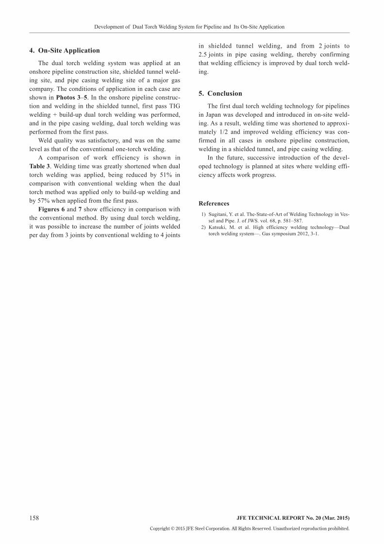
Photo 5 Appearance of pipe casing welding
Fig. 6 Example of cycle time in the case of welding in the shielded tunnel
Table 3 Comparison of welding efficiency
Applicable sectors
O. D. × W. T.(mm)
Welding method
Welding time (min) Cycle time (min)
(Dual)1 Torch Dual
Onshore 610 × 18.6 T + S 104 53 70
Shielded tunnel 610 × 18.6 T + S 104 53 80
Pipe casing 610 × 15.6 S 90 51 210
O. D.: Outside diameter, W. T.: Wall thickness
Fig. 7 Example of cycle time in the case of pipe casing welding
158 JFETECHNICALREPORTNo.20(Mar.2015)
Development of Dual Torch Welding System for Pipeline and Its On-Site Application
Copyright © 2015 JFE Steel Corporation. All Rights Reserved. Unauthorized reproduction prohibited.
in shielded tunnel welding, and from 2 joints to 2.5 joints in pipe casing welding, thereby confirming that welding efficiency is improved by dual torch weld-ing.
5. Conclusion
The first dual torch welding technology for pipelines in Japan was developed and introduced in on-site weld-ing. As a result, welding time was shortened to approxi-mately 1/2 and improved welding efficiency was con-firmed in all cases in onshore pipeline construction, welding in a shielded tunnel, and pipe casing welding.
In the future, successive introduction of the devel-oped technology is planned at sites where welding effi-ciency affects work progress.
References 1) Sugitani, Y. et al. The-State-of-Art of Welding Technology in Ves-
sel and Pipe. J. of JWS. vol. 68, p. 581–587. 2) Katsuki, M. et al. High efficiency welding technology—Dual
torch welding system—. Gas symposium 2012, 3-1.
4. On-SiteApplication
The dual torch welding system was applied at an onshore pipeline construction site, shielded tunnel weld-ing site, and pipe casing welding site of a major gas company. The conditions of application in each case are shown in Photos3–5. In the onshore pipeline construc-tion and welding in the shielded tunnel, first pass TIG welding + build-up dual torch welding was performed, and in the pipe casing welding, dual torch welding was performed from the first pass.
Weld quality was satisfactory, and was on the same level as that of the conventional one-torch welding.
A comparison of work efficiency is shown in Table3. Welding time was greatly shortened when dual torch welding was applied, being reduced by 51% in comparison with conventional welding when the dual torch method was applied only to build-up welding and by 57% when applied from the first pass.
Figures6 and 7 show efficiency in comparison with the conventional method. By using dual torch welding, it was possible to increase the number of joints welded per day from 3 joints by conventional welding to 4 joints